EP2131490A1 - Distortion correction control apparatus and distortion correction control method - Google Patents
Distortion correction control apparatus and distortion correction control method Download PDFInfo
- Publication number
- EP2131490A1 EP2131490A1 EP07740102A EP07740102A EP2131490A1 EP 2131490 A1 EP2131490 A1 EP 2131490A1 EP 07740102 A EP07740102 A EP 07740102A EP 07740102 A EP07740102 A EP 07740102A EP 2131490 A1 EP2131490 A1 EP 2131490A1
- Authority
- EP
- European Patent Office
- Prior art keywords
- distortion correction
- burst
- input signal
- distortion
- correction coefficient
- Prior art date
- Legal status (The legal status is an assumption and is not a legal conclusion. Google has not performed a legal analysis and makes no representation as to the accuracy of the status listed.)
- Granted
Links
Images






Classifications
-
- H—ELECTRICITY
- H03—ELECTRONIC CIRCUITRY
- H03F—AMPLIFIERS
- H03F1/00—Details of amplifiers with only discharge tubes, only semiconductor devices or only unspecified devices as amplifying elements
- H03F1/32—Modifications of amplifiers to reduce non-linear distortion
-
- H—ELECTRICITY
- H03—ELECTRONIC CIRCUITRY
- H03F—AMPLIFIERS
- H03F1/00—Details of amplifiers with only discharge tubes, only semiconductor devices or only unspecified devices as amplifying elements
- H03F1/32—Modifications of amplifiers to reduce non-linear distortion
- H03F1/3241—Modifications of amplifiers to reduce non-linear distortion using predistortion circuits
-
- H—ELECTRICITY
- H03—ELECTRONIC CIRCUITRY
- H03F—AMPLIFIERS
- H03F1/00—Details of amplifiers with only discharge tubes, only semiconductor devices or only unspecified devices as amplifying elements
- H03F1/32—Modifications of amplifiers to reduce non-linear distortion
- H03F1/3241—Modifications of amplifiers to reduce non-linear distortion using predistortion circuits
- H03F1/3247—Modifications of amplifiers to reduce non-linear distortion using predistortion circuits using feedback acting on predistortion circuits
-
- H—ELECTRICITY
- H03—ELECTRONIC CIRCUITRY
- H03F—AMPLIFIERS
- H03F3/00—Amplifiers with only discharge tubes or only semiconductor devices as amplifying elements
- H03F3/189—High-frequency amplifiers, e.g. radio frequency amplifiers
- H03F3/19—High-frequency amplifiers, e.g. radio frequency amplifiers with semiconductor devices only
Definitions
- the present invention relates to a distortion correction control apparatus and a distortion correction control method which are to be applied to a wireless communication system.
- OFDM orthogonal frequency division multiplexing
- an amplifier has amplifier operation points set to AB to B grades to improve power efficiency.
- the amount of current flowing to the amplifier during a no-signal period is small.
- a signal is suddenly input (burst ON) from the burst-OFF period, a current rapidly flows to an amplifier power source system.
- the power source system cannot follow such a sudden change in current value, causing current and voltage waveforms to exhibit transient responses (refer to FIG. 1 ).
- Patent Document 1 discloses a technique of adjusting an amplifier input signal to correct an amplifier distortion caused by burst transmission. This technique is characterized by measuring leading and trailing of a burst signal during transmission and performing a burst correction operation according to the leading and trailing thus measured.
- Patent Document 2 discloses a technique of restraining sudden rising to suppress burst distortion. This technique is characterized by suppressing the occurrence of burst distortion itself via ramp processing to gradually increase transmission outputs.
- a built-in correction coefficient is used, which does not follow the changes in amplifier characteristics. Because the amplifier undergoes changes in its characteristics due to a temperature or a passage of time, the amplifier has to maintain correction accuracy of burst distortion by adaptively updating the correction coefficient.
- a ramp operation is performed, which suppresses sudden rising of a transmission signal to gradually increase outputs.
- a signal rising period has to be provided before burst-ON or a signal has to be gradually raised after burst-ON, which causes deformation of a waveform of an amplifier output signal.
- An object of the present invention is to provide a technique capable of adaptively correcting a distortion (burst distortion) caused by burst transmission, to thereby enable improvement of environmental resistance of a transmission amplifier.
- Another object of the present invention is to provide a technique that enables good nonlinear distortion compensation even when burst transmission is executed in a transmission amplifier where nonlinear distortion occurs.
- Another object of the present invention is to provide a technique that enables a configuration with a small circuit size by using a prescribed function such as a sine function or an exponential function for distortion correction.
- the present invention provides a distortion correction control apparatus for compensating for burst distortion of a transmission amplifier caused by a burst of an input signal of a transmission target, which includes: generation means for generating a distortion correction coefficient having reverse characteristics to the burst distortion; means for multiplying the distortion correction coefficient output from the generation means by the input signal or adding the distortion correction coefficient output from the generation means to the input signal, upon reception of burst information notifying of switching between presence and absence of the input signal; and update means for updating, based on the input signal and a branch signal fed back as an output signal of the transmission amplifier, parameters of functions used for adaptively generating the distortion correction coefficient, and for inputting the updated parameters to the generation means.
- the functions for adaptively generating the distortion correction coefficient are a sine function and an exponential function.
- the sine function includes, as parameters thereof, an amplitude, a cycle, and an initial phase
- the exponential function includes, as parameters thereof, attenuation amounts.
- an optimal correction coefficient may be maintained even when amplifier characteristics undergo change due to a temperature or a passage of time/years.
- a burst distortion may be corrected without deforming a waveform of an amplifier output signal by ramp processing or the like.
- a burst distortion correction control apparatus employs, to correct an amplifier distortion (burst distortion) caused by burst characteristics of an input signal (baseband signal) x(t) of a transmission target, a configuration in which the input signal x(t) to a transmission amplifier (RF amplifier) 1 is multiplied by (or may be added to) a correction coefficient.
- an amplifier distortion burst distortion
- the correction coefficient (burst distortion correction coefficient) is generated to be output by a burst correction coefficient generation unit 2 by using burst information that is a signal (signal notifying of timing of burst (start) ON) notifying of switching between presence and absence of an input signal as a reference (opportunity), and the input signal x(t) is multiplied by the burst information as reverse characteristics to the burst distortion by a multiplier 3.
- the burst distortion correction coefficient is generated by using a function in the burst correction coefficient generation unit 2.
- a parameter update unit 4 updates parameters of the functions for adaptively generating a burst distortion correction coefficient based on the input signal x(t) and a branch signal y(t) as reference signals.
- the branch signal (FB signal) y(t) is a signal obtained as partial feedback of the output signal y(t) from the transmission amplifier 1, and is equivalent to the output signal y(t).
- the burst distortion correction coefficient is generated, in the burst correction coefficient generation unit 2, by two components of vibration and attenuation.
- a burst distortion correction coefficient may be represented by the following expression 1.
- g ⁇ t - t 0 A ⁇ sin 2 ⁇ ⁇ ⁇ t - t 0 T + ⁇ ⁇ e - ⁇ ⁇ t - t 0
- A, T, ⁇ , and ⁇ are parameters of sine and exponential functions to adaptively generate a burst distortion correction coefficient.
- A, T, and ⁇ respectively denote an amplitude, a cycle, and an initial phase of the sine function, and ⁇ denotes an attenuation amount of the exponential function (e).
- the burst distortion correction coefficient output from the burst correction coefficient generation unit 2, which is multiplied by or added to the input signal x(t) of a transmission target, is a correction coefficient based on a passage of time from switching between presence and absence of an input signal.
- the burst correction coefficient generation unit 2 may employ a configuration shown in FIG. 3 .
- the burst correction coefficient generation unit 2 includes an amplitude distortion correction signal generation unit 2A and a phase distortion correction signal generation unit 2B, and updated parameters A, T, ⁇ , and ⁇ are input from the parameter update unit 4.
- the amplitude distortion correction signal generation unit 2A and the phase distortion correction signal generation unit 2B each include a sine function generation unit 2A1, an exponential function generation unit 2A2, and a multiplier 2A3.
- sine and exponential functions multiplied by the multiplier 2A3 are output as an amplitude distortion correction signal a(t) of the burst distortion, to a multiplier 2C.
- sine and exponential functions multiplied by the multiplier 2A3 are output as a phase distortion correction signal e j ⁇ (t) of the burst distortion, to the multiplier 2C.
- the amplitude distortion correction signal a(t) of burst distortion and the phase distortion correction signal e j ⁇ (t) of the burst distortion are input to the multiplier 3.
- the burst distortion correction control apparatus shown in FIG. 2 executes digital signal processing, and therefore includes a digital/analog (D/A) converter disposed on an input side (front stage) to the transmission amplifier 1 and an analog/digital (A/D) converter disposed on a reception line (rear stage) of a branch signaly(t) of an output side of the transmission amplifier 1.
- D/A digital/analog
- A/D analog/digital
- a quadrature modulator In the front and rear stages of the transmission amplifier 1, a quadrature modulator, a quadrature demodulator, and a local oscillator are disposed. However, drawings of these components are omitted for simpler description.
- the first one of the methods includes a method of snooping burst information from an OFDM signal generation unit 4 shown in FIG. 4A .
- An OFDM signal is generated on a block unit basis using inverse fast Fourier transform (IFFT).
- IFFT inverse fast Fourier transform
- a burst occurs in a processing unit of this IFFT.
- Burst information is obtained by checking whether an input signal to an IFFT processing unit 51 has switched from all"0" to burst-ON, and whether a signal after IFFT processing has switched from all"0" to burst-ON.
- Whether the input signal to the IFFT processing unit 51 has switched from all"0" to burst-ON is determined by a serial/parallel (S/P) converter 52 to obtain burst information. This determination may be performed based on an output signal from the IFFT processing unit 51 to obtain burst information.
- S/P serial/parallel
- the second one of the methods includes a method of automatically determining whether an input signal x(t) of a transmission target is predetermined time zero and using the input signal x(t) as burst information.
- FIG. 4B illustrates a specific example of independently generating burst information.
- a signal zero determination unit 61 determines whether the input signal x(t) is a zero (0) signal. If the signal is a zero signal, a counter 62 of a rear stage is reset. If the signal is not a zero signal, the counter 62 is counted up.
- a counter value determination unit 63 if a counter value has reached a predetermined value, a pulse of burst information is generated determining that a burst-ON period has been started.
- a delay circuit (Delay) for delaying the input signal x(t) by processing time in the burst information generation unit 6.
- FIG. 5 illustrates a relationship between a status of a burst distortion caused by a burst signal in the transmission amplifier 1 and a burst distortion correction coefficient (correction signal).
- the burst distortion is a distortion changed as amplitude distortion and phase distortion with a passage of time from burst-ON and gradually converged with time.
- the burst distortion correction coefficient that is reverse in characteristics is obtained by function approximation.
- a method of generating a burst distortion coercion coefficient by using a sine function and an attenuation function (exponential function) is employed as one method.
- the sine function gradually making a cycle shorter with a passage of time from burst-ON enables more accurate approximation.
- FIG. 6 illustrates an example of determining a cycle T and an initial phase ⁇ of the sine function.
- the parameter update unit 4 captures timing (time/interval) at which the burst distortion becomes zero in a burst-ON section to determine (estimate) a cycle T and an initial phase ⁇ .
- FIG. 7 illustrates a configuration of a burst distortion correction control apparatus according to a second embodiment of the present invention.
- the second embodiment is a modified example of the basic configuration of the first embodiment shown in FIG. 2 .
- the burst distortion correction control apparatus includes a burst correction coefficient generation unit 2, a multiplier 3, a parameter update unit 4, and an adjacent channel leakage power ratio (ACLR) measurement unit 7.
- a burst correction coefficient generation unit 2 a multiplier 3, a parameter update unit 4, and an adjacent channel leakage power ratio (ACLR) measurement unit 7.
- ACLR adjacent channel leakage power ratio
- parameters are determined by ACLR measurement.
- an ACLR of a branch signal (FB signal) y(t) obtained by feeding back a part of an output signal y(t) from a transmission amplifier 1 is calculated to determine parameters for function approximation.
- the ACLR measurement unit 7 performs frequency analysis for the branch signal y(t) to measure leakage power of a frequency adjacent to an input signal x(t).
- FFT fast Fourier transform
- the ACLR measurement unit 7 captures the branch signal y(t) as input data necessary for FFT analysis according to an ACLR measurement request from the parameter update unit 4.
- the ACLR measurement unit 7 performs FFT processing for the captured branch signal y(t) to set the processed branch signal y(t) as frequency data, and measures an ACLR.
- the obtained ACLR is reported to the parameter update unit 4.
- FIG. 8 illustrates an example of a parameter determination procedure based on ACLR measurement.
- the ACLR measurement unit 7 determines parameters of a sine function and an attenuation function (exponential function) where an ACLR of the branch signal y(t) is best.
- the parameters of an initial phase ⁇ , a cycle T, an amplitude A, and an attenuation amount ⁇ are determined in the stated order (steps S81 to S84).
- order of determining the parameters is not limited to this order.
- FIG. 9 illustrates a parameter determination procedure in which parameter determination by ACLR measurement by the ACLR measurement unit 7 is combined with the method for determining a cycle T and an initial phase ⁇ by the parameter update unit 4 described above referring to FIG. 6 .
- the parameter update unit 4 captures timing (time/interval) at which the burst distortion becomes zero in a burst-ON section to determine an initial phase ⁇ and a cycle T of the sine function (steps S91 and S92).
- the ACLR measurement unit 7 determines an amplitude A and an attenuation amount ⁇ of the sine function by ACLR measurement (step S93 and S94).
- the burst distortion correction control apparatus of the second embodiment includes a nonlinear distortion compensation unit ND.
- the nonlinear distortion compensation unit ND compensates for nonlinear distortion of the transmission amplifier 1 by digital predistortion (DPD). Details on DPD may be easily understood by referring to Patent Document 4, and thus description thereof will be omitted.
- DPD digital predistortion
- FIG. 10 illustrates a configuration of a burst distortion correction control apparatus according to a third embodiment of the present invention.
- the third embodiment is another modified example of the basic configuration of the second embodiment shown in FIG. 2 .
- the burst distortion correction control apparatus includes a burst correction coefficient generation unit 2, a multiplier 3, a parameter update unit 4, and an error measurement unit 7.
- parameters are determined by error measurement.
- a branch signal (FB signal) obtained by feeding back a part of output signal y(t) from a transmission amplifier 1 is obtained, and parameters A, T, ⁇ , and ⁇ which minimize the error are determined (selected) for function approximation.
- FIG. 11 illustrates an example of a parameter determination procedure by error measurement.
- the error measurement unit 8 determines parameters of a sine function and an attenuation function (exponential function) where an error between the input signal x(t) and the branch signal y(t) is minimum.
- the parameters of an initial phase ⁇ , a cycle T, an amplitude A, and an attenuation amount ⁇ are determined in the stated order (steps S111 to S114).
- the order of determining parameters is not limited to this.
- the error measurement unit 8 may employ a method of executing sequential processing to determine optimal parameters.
- a method of determining an initial phase ⁇ of a sine function will be described as an example.
- the error measurement unit 8 performs error measurement based on a currently set initial phase ⁇ n .
- the error measurement unit 8 sets the initial phase ⁇ n to an initial phase ⁇ n+ ⁇ and an initial phase ⁇ n- ⁇ obtained by shifting the initial phase by a small amount ⁇ , and measures again an error therebetween. As shown in FIG. 12 , if an error is minimum at the initial phase ⁇ n , ⁇ n is determined to be an optimal initial phase to finish the processing.
- FIG. 14 illustrates an example where an error is larger as an initial phase ⁇ is larger.
- FIG. 15 illustrates a configuration of a burst distortion correction control apparatus according to a fourth embodiment of the present invention.
- the fourth embodiment is further another modified example of the basic configuration of the first embodiment shown in FIG. 2 .
- the burst distortion correction control apparatus of the fourth embodiment employs a configuration where the burst distortion correction coefficient generated in the basic configuration of the first embodiment described above is adjusted according to an average size (amplitude) of input signals x(t) of transmission targets.
- the burst distortion correction control apparatus further includes a transmission level measurement unit 9 for obtaining an average size of input signals x(t).
- the transmission level measurement unit 8 obtains an average power of the input signals x(t).
- a burst distortion correction coefficient is output from a burst correction coefficient generation unit 2 upon reception of a signal (burst signal) notifying of burst-ON timing.
- the burst distortion correction coefficient thus output is multiplied by the average power obtained by the transmission level measurement unit 9, via a multiplier 10.
- a result of this multiplying is multiplied as reverse characteristics of burst distortion by the input signal x(t), by a multiplier 3.
- adjustment is performed to prevent a change in size of a burst correction coefficient following an instantaneous change (for each sampling point).
- burst distortion correction control apparatus of the fourth embodiment are similar to those of the burst distortion correction control apparatus of the first embodiment described above.
- FIG. 16 illustrates a status of a change in a burst distortion made according to a size of the input signal x(t) of a transmission target. As apparent from FIG. 16 , burst distortion during burst transmission is larger when an input signal x(t) is larger.
- FIGS. 17 and 18 each illustrate a configuration of a burst distortion correction control apparatus according to a fifth embodiment of the present invention.
- the fifth embodiment is still further another modified example of the basic configuration of the first embodiment shown in FIG. 2 .
- Each of the burst distortion correction control apparatuses of the fifth embodiment employs aconfigurationwhere a burst distortion correction coefficient is generated by a burst correction coefficient generation unit 2 using a low-pass filter (LPF) 20, and parameters of functions for adaptively generating a burst distortion correction coefficient are updated by a parameter update unit 4 (LPF and rectangular wave parameter update unit 40).
- LPF low-pass filter
- the burst correction coefficient generation unit 2 includes a rectangular wave generation unit 21 to use approximation of a waveform of burst distortion by a response of the LPF 20 to a rectangular wave.
- the parameter update unit 40 adjusts a burst distortion correction coefficient by using a shape, an order, and a cut-off frequency of the LPF 20 as parameters.
- the parameter update unit 40 reproduces, based on the fact that a burst distortion becomes gradually smaller with a passage of time, the burst distortion by gradually reducing a rectangular wave generated by the rectangular wave generation unit 21.
- burst distortion correction is controlled by using the FIR filter as the LPF 20
- totally five types of parameters may be employed.
- the FIR filter itself there are three types including a tap length 1, a cut-off frequency ⁇ c , and a window function (Kaiser window) parameter ⁇ .
- a window function Keriser window
- rectangular wave generation parameters input to the filter there are two types including an amplitude A rct and an attenuation amount ⁇ rct of a rectangular wave.
- the method based on the ACLR measurement or the method based on the error measurement may be employed.
- a tap coefficient tap k is obtained by the following expression 2.
- 1 denotes a tap length
- T denotes a sampling frequency
- ⁇ c denotes a cut-off frequency
- multiplying the tap coefficient tap k by a window function enables adjustment of attenuation amounts of a passband ripple, a transfer band, and a block band.
- window functions including Humming widow, Han window, Blackman window, and Kaiser window. Changing a type of a window function enables adjustment of a burst distortion correction coefficient.
- an optional window function may be generated by adjusting the parameter ⁇ . Thus, adjustment of the burst distortion correction coefficient is easy.
- the parameter update unit 40 may adjust the burst distortion correction coefficient by changing a filter shape, an order, and constants L and C of the LC circuit.
- Analog filter shapes include Butterworth type, Chebychev type, Gausssian type, and Vessel type, which are selectively used according to the characteristics of burst distortion.
- the filters excluding Vessel type where group delay characteristics in a band are flat may be employed.
- Orders may also be selectively used according to the characteristics of burst distortion. For example, adjustment is made by employing a filter of a small order when the burst distortion is great, and a filer of a large order when the burst distortion is great.
- constants L and C of the LC circuit may be changed.
- the constants L and C may be changed by employing an element that may vary constants of a used coil L and a used capacitor C.
- the parameter update unit 40 changes the L and C constants, a cut-off frequency and a block band attenuation amount of the LPF 20 are adjusted, with the result that the burst distortion correction coefficient is adjusted.
- the method based on the ACLR measurement or the method based on the error measurement described above may be employed.
- FIG. 19 illustrates a generation procedure of a burst distortion correction coefficient using the LPF 20 in the burst distortion correction control apparatus that employs a configuration shown in FIGS. 17 and 18 .
- the rectangular wave generation unit 21 detects burst-ON based on burst information notifying of switching between presence and absence of an input signal, and generates a rectangular wave corresponding to a length (time) generated by the burst distortion.
- the LPF 20 that has received the rectangular wave from the rectangular wave generation unit 21 generates and outputs a response to the rectangular wave.
- a reciprocal transformation unit 22 takes a number reciprocal to this response to multiply an input signal x(t) of a transmission target by the number by a multiplier 3.
- an adjacent channel leakage power ratio (ACLR) deteriorated by the influence of the burst distortion generated when a signal is burst-transmitted may be rectified.
- the burst distortion correction of each embodiment may be applied to any situation such as when power is supplied, where the presence and absence of an input signal is switched.
- a burst distortion correction coefficient may be generated highly accurately and fast by using an adjustment rectangular wave signal as an input signal.
- each embodiment described above is provided as a computer-executable program, and may be provided via a recording medium such as a CD-ROM or a flexible disk, and via a communication line.
- a plurality of optional processing operations or all of the embodiments may be selectively combined to be implemented.
Landscapes
- Engineering & Computer Science (AREA)
- Power Engineering (AREA)
- Physics & Mathematics (AREA)
- Nonlinear Science (AREA)
- Amplifiers (AREA)
Abstract
Description
- The present invention relates to a distortion correction control apparatus and a distortion correction control method which are to be applied to a wireless communication system.
- In a wireless communication system that employs a wireless transmission system such as orthogonal frequency division multiplexing (OFDM), signals of burst characteristics are often processed.
- In general, an amplifier has amplifier operation points set to AB to B grades to improve power efficiency. Thus, the amount of current flowing to the amplifier during a no-signal period (during a burst-OFF period) is small. When a signal is suddenly input (burst ON) from the burst-OFF period, a current rapidly flows to an amplifier power source system. The power source system cannot follow such a sudden change in current value, causing current and voltage waveforms to exhibit transient responses (refer to
FIG. 1 ). As a result, amplifier characteristics change. - As a related art of the present invention, techniques disclosed in the following two Patent Documents may be cited. First, Japanese Patent Application Laid-Open No.
2004-112252 - Second, Japanese Patent Application Laid-Open No.
H04-301950 - According to the technique described in
Patent Document 1, a built-in correction coefficient is used, which does not follow the changes in amplifier characteristics. Because the amplifier undergoes changes in its characteristics due to a temperature or a passage of time, the amplifier has to maintain correction accuracy of burst distortion by adaptively updating the correction coefficient. - According to the technique described in
Patent Document 2, a ramp operation is performed, which suppresses sudden rising of a transmission signal to gradually increase outputs. In this technique, a signal rising period has to be provided before burst-ON or a signal has to be gradually raised after burst-ON, which causes deformation of a waveform of an amplifier output signal.
The following are related arts to the invention. - [Patent document 1] Japanese Patent Laid-Open Publication No.
JP 2004-112252 - [Patent document 2] Japanese Patent Laid-Open Publication No.
JP H04-301950 - [Patent document 3] Japanese Patent Laid-Open Publication No.
JP H09-153849 - [Patent document 4] Japanese Patent No.
JP 3560398 - An object of the present invention is to provide a technique capable of adaptively correcting a distortion (burst distortion) caused by burst transmission, to thereby enable improvement of environmental resistance of a transmission amplifier.
- Another object of the present invention is to provide a technique that enables good nonlinear distortion compensation even when burst transmission is executed in a transmission amplifier where nonlinear distortion occurs.
- Another object of the present invention is to provide a technique that enables a configuration with a small circuit size by using a prescribed function such as a sine function or an exponential function for distortion correction.
- In order to solve the above-mentioned problems, the present invention provides a distortion correction control apparatus for compensating for burst distortion of a transmission amplifier caused by a burst of an input signal of a transmission target, which includes: generation means for generating a distortion correction coefficient having reverse characteristics to the burst distortion; means for multiplying the distortion correction coefficient output from the generation means by the input signal or adding the distortion correction coefficient output from the generation means to the input signal, upon reception of burst information notifying of switching between presence and absence of the input signal; and update means for updating, based on the input signal and a branch signal fed back as an output signal of the transmission amplifier, parameters of functions used for adaptively generating the distortion correction coefficient, and for inputting the updated parameters to the generation means.
- In the distortion correction control apparatus described above, the functions for adaptively generating the distortion correction coefficient are a sine function and an exponential function. The sine function includes, as parameters thereof, an amplitude, a cycle, and an initial phase, and the exponential function includes, as parameters thereof, attenuation amounts.
- According to the present invention, to correct an amplifier distortion (burst distortion) caused by burst transmission, reverse characteristics are given to an input signal to correct the distortion, a correction coefficient is generated by a function, and parameters are adaptively updated. Thus, an optimal correction coefficient may be maintained even when amplifier characteristics undergo change due to a temperature or a passage of time/years.
- According to the present invention, a burst distortion may be corrected without deforming a waveform of an amplifier output signal by ramp processing or the like.
- Other objects, features, and advantages of the present invention will become apparent upon reading of the following detailed description taken in conjunction with drawings and appended claims.
-
-
FIG. 1 is a diagram illustrating input and output signals in a transmission amplifier during burst transmission; -
FIG. 2 is a block diagram illustrating a burst distortion correction control apparatus according to a first embodiment of the present invention; -
FIG. 3 is a block diagram illustrating a configuration example of the burst correction coefficient generation unit ofFIG. 2 ; -
FIG. 4A illustrates a first method of obtaining burst information; -
FIG. 4B illustrates a second method of obtaining burst information; -
FIG. 5 is a graph illustrating a relationship between burst distortion and a burst distortion correction coefficient in the transmission amplifier; -
FIG. 6 is a graph illustrating estimation of a cycle and an initial phase of a sine function; -
FIG. 7 is a block diagram illustrating a burst distortion correction control apparatus according to a second embodiment of the present invention; -
FIG. 8 is a flowchart illustrating a parameter determination procedure based on ACLR; -
FIG. 9 is a flowchart illustrating a parameter determination procedure based on combination; -
-
FIG. 10 is a block diagram illustrating a burst distortion correction control apparatus according to a third embodiment of the present invention; -
FIG. 11 is a flowchart illustrating a parameter determination procedure based on error; -
FIG. 12 is a graph for illustrating a parameter determination procedure based on error; -
FIG. 13 is a graph for illustrating a parameter determination procedure based on error; -
FIG. 14 is a graph for illustrating a parameter determination procedure based on error; -
FIG. 15 is a block diagram illustrating a burst distortion correction control apparatus according to a fourth embodiment of the present invention; -
FIG. 16 is a graph illustrating burst distortion that changes in accordance with a size of an input signal; -
FIG. 17 is a block diagram illustrating a burst distortion correction control apparatus according to a fifth embodiment of the present invention; -
FIG. 18 is a block diagram illustrating the burst distortion correction control apparatus according to the fifth embodiment of the present invention; and -
FIG. 19 is a flowchart illustrating a generation procedure of a burst distortion correction coefficient using LPF. - Hereinafter, referring to the accompanying drawings, the present invention will be described more in detail. The drawings illustrate the preferred embodiments of the present invention. However, it should be understood that the invention may be implemented by many different embodiments, not limited to the embodiments described herein. Rather, the embodiments are provided so that the disclosure is full and complete, and a scope of the invention is fully understandable to those skilled in the art.
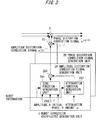
- Referring to
FIG. 2 illustrating a configuration (basic configuration) of a first embodiment of the present invention, a burst distortion correction control apparatus employs, to correct an amplifier distortion (burst distortion) caused by burst characteristics of an input signal (baseband signal) x(t) of a transmission target, a configuration in which the input signal x(t) to a transmission amplifier (RF amplifier) 1 is multiplied by (or may be added to) a correction coefficient. - The correction coefficient (burst distortion correction coefficient) is generated to be output by a burst correction
coefficient generation unit 2 by using burst information that is a signal (signal notifying of timing of burst (start) ON) notifying of switching between presence and absence of an input signal as a reference (opportunity), and the input signal x(t) is multiplied by the burst information as reverse characteristics to the burst distortion by amultiplier 3. The burst distortion correction coefficient is generated by using a function in the burst correctioncoefficient generation unit 2. - A
parameter update unit 4 updates parameters of the functions for adaptively generating a burst distortion correction coefficient based on the input signal x(t) and a branch signal y(t) as reference signals. The branch signal (FB signal) y(t) is a signal obtained as partial feedback of the output signal y(t) from thetransmission amplifier 1, and is equivalent to the output signal y(t). - More specifically, the burst distortion correction coefficient is generated, in the burst correction
coefficient generation unit 2, by two components of vibration and attenuation. For example, when a sine function is substituted for the vibration function and an exp function (exponential function) is substituted for the attenuation function, a burst distortion correction coefficient may be represented by the followingexpression 1. -

- In the
expression 1, A, T, θ, and ρ are parameters of sine and exponential functions to adaptively generate a burst distortion correction coefficient. A, T, and θ respectively denote an amplitude, a cycle, and an initial phase of the sine function, and ρ denotes an attenuation amount of the exponential function (e). The burst distortion correction coefficient output from the burst correctioncoefficient generation unit 2, which is multiplied by or added to the input signal x(t) of a transmission target, is a correction coefficient based on a passage of time from switching between presence and absence of an input signal. - When the parameters described above are used for burst distortion correction, the burst correction
coefficient generation unit 2 may employ a configuration shown inFIG. 3 . As shown inFIG. 3 , the burst correctioncoefficient generation unit 2 includes an amplitude distortion correctionsignal generation unit 2A and a phase distortion correctionsignal generation unit 2B, and updated parameters A, T, θ, and ρ are input from theparameter update unit 4. - The amplitude distortion correction
signal generation unit 2A and the phase distortion correctionsignal generation unit 2B each include a sine function generation unit 2A1, an exponential function generation unit 2A2, and a multiplier 2A3. In the amplitude distortion correctionsignal generation unit 2A, sine and exponential functions multiplied by the multiplier 2A3 are output as an amplitude distortion correction signal a(t) of the burst distortion, to a multiplier 2C. In the phase distortion correctionsignal generation unit 2B, sine and exponential functions multiplied by the multiplier 2A3 are output as a phase distortion correction signal ejφ(t) of the burst distortion, to the multiplier 2C. The amplitude distortion correction signal a(t) of burst distortion and the phase distortion correction signal ejφ(t) of the burst distortion are input to themultiplier 3. - The burst distortion correction control apparatus shown in
FIG. 2 executes digital signal processing, and therefore includes a digital/analog (D/A) converter disposed on an input side (front stage) to thetransmission amplifier 1 and an analog/digital (A/D) converter disposed on a reception line (rear stage) of a branch signaly(t) of an output side of thetransmission amplifier 1. However, these components are not shown. Unless specified otherwise, drawings of these components are omitted in the other embodiments. - In the front and rear stages of the
transmission amplifier 1, a quadrature modulator, a quadrature demodulator, and a local oscillator are disposed. However, drawings of these components are omitted for simpler description. - Next, two types of methods that enable the burst correction
coefficient generation unit 2 to obtain burst information as a signal notifying of burst-ON timing will be described. - The first one of the methods includes a method of snooping burst information from an OFDM
signal generation unit 4 shown inFIG. 4A . An OFDM signal is generated on a block unit basis using inverse fast Fourier transform (IFFT). A burst occurs in a processing unit of this IFFT. Burst information is obtained by checking whether an input signal to anIFFT processing unit 51 has switched from all"0" to burst-ON, and whether a signal after IFFT processing has switched from all"0" to burst-ON. - Whether the input signal to the
IFFT processing unit 51 has switched from all"0" to burst-ON is determined by a serial/parallel (S/P)converter 52 to obtain burst information. This determination may be performed based on an output signal from theIFFT processing unit 51 to obtain burst information. - The second one of the methods includes a method of automatically determining whether an input signal x(t) of a transmission target is predetermined time zero and using the input signal x(t) as burst information.
FIG. 4B illustrates a specific example of independently generating burst information. - In a burst
information generation unit 6, a signal zerodetermination unit 61 determines whether the input signal x(t) is a zero (0) signal. If the signal is a zero signal, acounter 62 of a rear stage is reset. If the signal is not a zero signal, thecounter 62 is counted up. - In a counter
value determination unit 63, if a counter value has reached a predetermined value, a pulse of burst information is generated determining that a burst-ON period has been started. In the drawing, there is provided a delay circuit (Delay) for delaying the input signal x(t) by processing time in the burstinformation generation unit 6. -
FIG. 5 illustrates a relationship between a status of a burst distortion caused by a burst signal in thetransmission amplifier 1 and a burst distortion correction coefficient (correction signal). The burst distortion is a distortion changed as amplitude distortion and phase distortion with a passage of time from burst-ON and gradually converged with time. The burst distortion correction coefficient that is reverse in characteristics is obtained by function approximation. In this case, a method of generating a burst distortion coercion coefficient by using a sine function and an attenuation function (exponential function) is employed as one method. As for the sine function, gradually making a cycle shorter with a passage of time from burst-ON enables more accurate approximation. -
FIG. 6 illustrates an example of determining a cycle T and an initial phase θ of the sine function. Theparameter update unit 4 captures timing (time/interval) at which the burst distortion becomes zero in a burst-ON section to determine (estimate) a cycle T and an initial phase θ. -
FIG. 7 illustrates a configuration of a burst distortion correction control apparatus according to a second embodiment of the present invention. The second embodiment is a modified example of the basic configuration of the first embodiment shown inFIG. 2 . - Referring to
FIG. 7 , the burst distortion correction control apparatus includes a burst correctioncoefficient generation unit 2, amultiplier 3, aparameter update unit 4, and an adjacent channel leakage power ratio (ACLR)measurement unit 7. - In the burst distortion correction control apparatus, parameters are determined by ACLR measurement. Thus, an ACLR of a branch signal (FB signal) y(t) obtained by feeding back a part of an output signal y(t) from a
transmission amplifier 1 is calculated to determine parameters for function approximation. - The
ACLR measurement unit 7 performs frequency analysis for the branch signal y(t) to measure leakage power of a frequency adjacent to an input signal x(t). For this frequency analysis, fast Fourier transform (FFT), which is digital signal processing, is conveniently used. - The
ACLR measurement unit 7 captures the branch signal y(t) as input data necessary for FFT analysis according to an ACLR measurement request from theparameter update unit 4. TheACLR measurement unit 7 performs FFT processing for the captured branch signal y(t) to set the processed branch signal y(t) as frequency data, and measures an ACLR. The obtained ACLR is reported to theparameter update unit 4. -
FIG. 8 illustrates an example of a parameter determination procedure based on ACLR measurement. TheACLR measurement unit 7 determines parameters of a sine function and an attenuation function (exponential function) where an ACLR of the branch signal y(t) is best. The parameters of an initial phase θ, a cycle T, an amplitude A, and an attenuation amount ρ are determined in the stated order (steps S81 to S84). However, order of determining the parameters is not limited to this order. -
FIG. 9 illustrates a parameter determination procedure in which parameter determination by ACLR measurement by theACLR measurement unit 7 is combined with the method for determining a cycle T and an initial phase θ by theparameter update unit 4 described above referring toFIG. 6 . In other words, theparameter update unit 4 captures timing (time/interval) at which the burst distortion becomes zero in a burst-ON section to determine an initial phase θ and a cycle T of the sine function (steps S91 and S92). Then, theACLR measurement unit 7 determines an amplitude A and an attenuation amount ρ of the sine function by ACLR measurement (step S93 and S94). - Referring back to
FIG. 7 , the burst distortion correction control apparatus of the second embodiment includes a nonlinear distortion compensation unit ND. The nonlinear distortion compensation unit ND compensates for nonlinear distortion of thetransmission amplifier 1 by digital predistortion (DPD). Details on DPD may be easily understood by referring toPatent Document 4, and thus description thereof will be omitted. -
FIG. 10 illustrates a configuration of a burst distortion correction control apparatus according to a third embodiment of the present invention. The third embodiment is another modified example of the basic configuration of the second embodiment shown inFIG. 2 . - Referring to
FIG. 10 , the burst distortion correction control apparatus includes a burst correctioncoefficient generation unit 2, amultiplier 3, aparameter update unit 4, and anerror measurement unit 7. - In the burst distortion correction control apparatus, parameters are determined by error measurement. Thus, an error between an input signal x(t) as a reference signal and a branch signal (FB signal) obtained by feeding back a part of output signal y(t) from a
transmission amplifier 1 is obtained, and parameters A, T, θ, and ρ which minimize the error are determined (selected) for function approximation. -
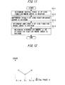
FIG. 11 illustrates an example of a parameter determination procedure by error measurement. Theerror measurement unit 8 determines parameters of a sine function and an attenuation function (exponential function) where an error between the input signal x(t) and the branch signal y(t) is minimum. The parameters of an initial phase θ, a cycle T, an amplitude A, and an attenuation amount ρ are determined in the stated order (steps S111 to S114). However, the order of determining parameters is not limited to this. - The
error measurement unit 8 may employ a method of executing sequential processing to determine optimal parameters. A method of determining an initial phase θ of a sine function will be described as an example. - First, the
error measurement unit 8 performs error measurement based on a currently set initial phase θn. Theerror measurement unit 8 sets the initial phase θn to an initial phase θn+α and an initial phase θn-α obtained by shifting the initial phase by a small amount α, and measures again an error therebetween. As shown inFIG. 12 , if an error is minimum at the initial phase θn, θn is determined to be an optimal initial phase to finish the processing. - If the initial phase θn is not optimal, errors obtained at three initial phases exhibit monotonous decreases or increases.
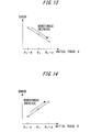
FIG. 13 illustrates an example where an error is smaller as an initial phase θ is larger. In this case, replacement of θn=θn+α is set to measure errors at the three points again, thereby searching for an optimal initial phase. -
FIG. 14 illustrates an example where an error is larger as an initial phase θ is larger. In this case, replacement of θn=θn-α is set to measure errors at the three points again to search for an optimal initial phase. -
FIG. 15 illustrates a configuration of a burst distortion correction control apparatus according to a fourth embodiment of the present invention. The fourth embodiment is further another modified example of the basic configuration of the first embodiment shown inFIG. 2 . - The burst distortion correction control apparatus of the fourth embodiment employs a configuration where the burst distortion correction coefficient generated in the basic configuration of the first embodiment described above is adjusted according to an average size (amplitude) of input signals x(t) of transmission targets. Thus, the burst distortion correction control apparatus further includes a transmission
level measurement unit 9 for obtaining an average size of input signals x(t). - Specifically, the transmission
level measurement unit 8 obtains an average power of the input signals x(t). A burst distortion correction coefficient is output from a burst correctioncoefficient generation unit 2 upon reception of a signal (burst signal) notifying of burst-ON timing. The burst distortion correction coefficient thus output is multiplied by the average power obtained by the transmissionlevel measurement unit 9, via amultiplier 10. A result of this multiplying is multiplied as reverse characteristics of burst distortion by the input signal x(t), by amultiplier 3. - Accordingly, as in the case of the burst distortion correction control apparatus of the first embodiment, adjustment (control) is performed to prevent a change in size of a burst correction coefficient following an instantaneous change (for each sampling point).
- Other components and an operation of the burst distortion correction control apparatus of the fourth embodiment are similar to those of the burst distortion correction control apparatus of the first embodiment described above.
-
FIG. 16 illustrates a status of a change in a burst distortion made according to a size of the input signal x(t) of a transmission target. As apparent fromFIG. 16 , burst distortion during burst transmission is larger when an input signal x(t) is larger. -
FIGS. 17 and18 each illustrate a configuration of a burst distortion correction control apparatus according to a fifth embodiment of the present invention. The fifth embodiment is still further another modified example of the basic configuration of the first embodiment shown inFIG. 2 . - Each of the burst distortion correction control apparatuses of the fifth embodiment employs aconfigurationwhere a burst distortion correction coefficient is generated by a burst correction
coefficient generation unit 2 using a low-pass filter (LPF) 20, and parameters of functions for adaptively generating a burst distortion correction coefficient are updated by a parameter update unit 4 (LPF and rectangular wave parameter update unit 40). - The burst correction
coefficient generation unit 2 includes a rectangularwave generation unit 21 to use approximation of a waveform of burst distortion by a response of theLPF 20 to a rectangular wave. Theparameter update unit 40 adjusts a burst distortion correction coefficient by using a shape, an order, and a cut-off frequency of theLPF 20 as parameters. Theparameter update unit 40 reproduces, based on the fact that a burst distortion becomes gradually smaller with a passage of time, the burst distortion by gradually reducing a rectangular wave generated by the rectangularwave generation unit 21. - In the case of correcting a burst distortion by a digital filter, there are roughly two filter designing methods, including a method based on finite-duration impulse response (FIR) and a method based on infinite-duration impulse response (IIR). In this embodiment, there is employed a designing method using a FIR filter of high operation stability, and a description is given thereof.
- When burst distortion correction is controlled by using the FIR filter as the
LPF 20, totally five types of parameters may be employed. Regarding the FIR filter itself, there are three types including atap length 1, a cut-off frequency ωc, and a window function (Kaiser window) parameter β. As rectangular wave generation parameters input to the filter, there are two types including an amplitude Arct and an attenuation amount ρrct of a rectangular wave. For a method for adjusting these parameters, the method based on the ACLR measurement or the method based on the error measurement may be employed. - In the case of designing the LPF (FIR filter) 20 by a limited tap length, a tap coefficient tapk is obtained by the following
expression 2. -

- In the expression, 1 denotes a tap length, T denotes a sampling frequency, and ωc denotes a cut-off frequency.
- In the LPF of the limited tap length, multiplying the tap coefficient tapk by a window function enables adjustment of attenuation amounts of a passband ripple, a transfer band, and a block band. There are various window functions including Humming widow, Han window, Blackman window, and Kaiser window. Changing a type of a window function enables adjustment of a burst distortion correction coefficient. However, when Kaiser window having a variable adjust parameter β is employed, an optional window function may be generated by adjusting the parameter β. Thus, adjustment of the burst distortion correction coefficient is easy.
- On the other hand, when an analog filter is used as the
LPF 20, theparameter update unit 40 may adjust the burst distortion correction coefficient by changing a filter shape, an order, and constants L and C of the LC circuit. - Analog filter shapes include Butterworth type, Chebychev type, Gausssian type, and Vessel type, which are selectively used according to the characteristics of burst distortion. When correcting a phase distortion of a burst distortion, the filters excluding Vessel type where group delay characteristics in a band are flat may be employed.
- Orders may also be selectively used according to the characteristics of burst distortion. For example, adjustment is made by employing a filter of a small order when the burst distortion is great, and a filer of a large order when the burst distortion is great.
- To adjust the burst distortion correction coefficient based on adaptive control, constants L and C of the LC circuit may be changed. The constants L and C may be changed by employing an element that may vary constants of a used coil L and a used capacitor C. When the
parameter update unit 40 changes the L and C constants, a cut-off frequency and a block band attenuation amount of theLPF 20 are adjusted, with the result that the burst distortion correction coefficient is adjusted. For a parameter adjustment method, the method based on the ACLR measurement or the method based on the error measurement described above may be employed. -
FIG. 19 illustrates a generation procedure of a burst distortion correction coefficient using theLPF 20 in the burst distortion correction control apparatus that employs a configuration shown inFIGS. 17 and18 . First, the rectangularwave generation unit 21 detects burst-ON based on burst information notifying of switching between presence and absence of an input signal, and generates a rectangular wave corresponding to a length (time) generated by the burst distortion. TheLPF 20 that has received the rectangular wave from the rectangularwave generation unit 21 generates and outputs a response to the rectangular wave. Areciprocal transformation unit 22 takes a number reciprocal to this response to multiply an input signal x(t) of a transmission target by the number by amultiplier 3. - According to the burst distortion correction control apparatus of each embodiment, in the
transmission amplifier 1 where nonlinear distortion occurs, an adjacent channel leakage power ratio (ACLR) deteriorated by the influence of the burst distortion generated when a signal is burst-transmitted may be rectified. - The burst distortion correction of each embodiment may be applied to any situation such as when power is supplied, where the presence and absence of an input signal is switched. A burst distortion correction coefficient may be generated highly accurately and fast by using an adjustment rectangular wave signal as an input signal.
- The processing of each embodiment described above is provided as a computer-executable program, and may be provided via a recording medium such as a CD-ROM or a flexible disk, and via a communication line.
- A plurality of optional processing operations or all of the embodiments may be selectively combined to be implemented.
Claims (11)
- A distortion correction control apparatus for compensating for burst distortion of a transmission amplifier caused by a burst of an input signal of a transmission target, comprising:generation means for generating a distortion correction coefficient having reverse characteristics to the burst distortion;means for multiplying the distortion correction coefficient output from the generation means by the input signal or adding the distortion correction coefficient output from the generation means to the input signal, upon reception of burst information notifying of switching between presence and absence of the input signal; andupdate means for updating, based on the input signal and a branch signal fed back as an output signal of the transmission amplifier, parameters of functions used for adaptively generating the distortion correction coefficient, and for inputting the updated parameters to the generation means.
- The distortion correction control apparatus according to claim 1, wherein the functions for adaptively generating the distortion correction coefficient are a sine function and an exponential function.
- The distortion correction control apparatus according to claim 2, wherein the sine function includes, as parameters thereof, an amplitude, a cycle, and an initial phase, and the exponential function includes, as parameters thereof, attenuation amounts.
- The distortion correction control apparatus according to claim 3, wherein the update means determines the cycle of the parameters of the sine function based on time and an interval when the burst distortion becomes zero in a burst continuance section.
- The distortion correction control apparatus according to claim 3, wherein the update means determines the initial phase of the parameters of the sine function based on time and an interval when the burst distortion becomes zero in a burst continuance section.
- The distortion correction control apparatus according to claim 1, further comprising means for adjusting the parameters based on an error between the input signal as a reference signal and the branch signal.
- The distortion correction control apparatus according to claim 1, wherein the distortion correction coefficient multiplied by the input signal of the transmission target or added to the input signal of the transmission target is a correction coefficient according to a passage of time from switching between presence and absence of the input signal.
- The distortion correction control apparatus according to claim 1, wherein correction of the distortion is carried out for the input signal with respect to both an amplitude and a phase.
- The distortion correction control apparatus according to claim 1, further comprising means for adjusting a size of the distortion correction coefficient according to the amplitude of the input signal.
- The burst distortion correction control apparatus according to claim 1, further comprising means for obtaining average power of the input signal to adjust the distortion correction coefficient according to an average size of the input signal.
- A distortion correction control method of compensating for burst distortion of a transmission amplifier caused by a burst of an input signal of a transmission target, comprising the steps of:generating a distortion correction coefficient having reverse characteristics to the burst distortion;multiplying the generated distortion correction coefficient by the input signal or adding the generated distortion correction coefficient to the input signal, upon reception of burst information notifying of switching between presence and absence of the input signal; andupdating, based on the input signal and a branch signal fed back as an output signal of the transmission amplifier, parameters of functions used for adaptively generating the distortion correction coefficient, and inputting the updated parameters for generating the distortion correction coefficient.
Applications Claiming Priority (1)
| Application Number | Priority Date | Filing Date | Title |
|---|---|---|---|
| PCT/JP2007/056664 WO2008120318A1 (en) | 2007-03-28 | 2007-03-28 | Distortion correction control apparatus and distortion correction control method |
Publications (3)
| Publication Number | Publication Date |
|---|---|
| EP2131490A1 true EP2131490A1 (en) | 2009-12-09 |
| EP2131490A4 EP2131490A4 (en) | 2013-10-02 |
| EP2131490B1 EP2131490B1 (en) | 2017-08-16 |
Family
ID=39807911
Family Applications (1)
| Application Number | Title | Priority Date | Filing Date |
|---|---|---|---|
| EP07740102.4A Not-in-force EP2131490B1 (en) | 2007-03-28 | 2007-03-28 | Distortion correction control apparatus and distortion correction control method |
Country Status (6)
| Country | Link |
|---|---|
| US (1) | US7881404B2 (en) |
| EP (1) | EP2131490B1 (en) |
| JP (1) | JP5267455B2 (en) |
| KR (1) | KR101099228B1 (en) |
| CN (1) | CN101689834B (en) |
| WO (1) | WO2008120318A1 (en) |
Families Citing this family (7)
| Publication number | Priority date | Publication date | Assignee | Title |
|---|---|---|---|---|
| US8706062B1 (en) * | 2008-12-19 | 2014-04-22 | Scintera Networks, Inc. | Self-adaptive power amplification |
| JP2017050694A (en) | 2015-09-01 | 2017-03-09 | 富士通株式会社 | Wireless communication apparatus and burst distortion correction method |
| JP6720697B2 (en) * | 2016-05-27 | 2020-07-08 | 日本電気株式会社 | Distortion compensation circuit, distortion compensation method, and transmission device |
| JP7288744B2 (en) * | 2018-07-26 | 2023-06-08 | 日本無線株式会社 | Distortion compensation device and distortion compensation method |
| WO2023014609A1 (en) * | 2021-08-06 | 2023-02-09 | Apple Inc. | Enhanced communications for wireless power transfer |
| US11784512B2 (en) | 2021-08-06 | 2023-10-10 | Apple Inc. | Enhanced communications for wireless power transfer |
| KR20240036360A (en) | 2022-09-13 | 2024-03-20 | 삼성전자주식회사 | Wireless communication device and operating method of wireless communication device |
Family Cites Families (21)
| Publication number | Priority date | Publication date | Assignee | Title |
|---|---|---|---|---|
| JPS6220387A (en) * | 1985-07-19 | 1987-01-28 | Hitachi Ltd | Semiconductor laser drive method |
| JPH04301950A (en) | 1991-03-28 | 1992-10-26 | Oki Electric Ind Co Ltd | Linear amplifier |
| US5870668A (en) * | 1995-08-18 | 1999-02-09 | Fujitsu Limited | Amplifier having distortion compensation and base station for radio communication using the same |
| JP3560398B2 (en) | 1995-08-31 | 2004-09-02 | 富士通株式会社 | Amplifier with distortion compensation |
| US5903823A (en) * | 1995-09-19 | 1999-05-11 | Fujitsu Limited | Radio apparatus with distortion compensating function |
| JP3323715B2 (en) | 1995-11-30 | 2002-09-09 | 富士通株式会社 | Wireless device |
| US20040246891A1 (en) * | 1999-07-23 | 2004-12-09 | Hughes Electronics Corporation | Air interface frame formatting |
| US7058369B1 (en) * | 2001-11-21 | 2006-06-06 | Pmc-Sierra Inc. | Constant gain digital predistortion controller for linearization of non-linear amplifiers |
| JP3833968B2 (en) * | 2002-05-31 | 2006-10-18 | 株式会社東芝 | Radio device having DC offset canceller |
| JP4064770B2 (en) * | 2002-09-18 | 2008-03-19 | 株式会社日立国際電気 | Distortion compensation amplifier |
| JP3917509B2 (en) | 2002-12-06 | 2007-05-23 | 日本電信電話株式会社 | Nonlinear distortion compensator |
| US7822085B2 (en) * | 2003-06-27 | 2010-10-26 | Koninklijke Philips Electronics N.V. | Method of controlling a diode device for use in optical storage systems |
| JP4349857B2 (en) * | 2003-07-14 | 2009-10-21 | 富士通テン株式会社 | Wireless device |
| JP2005064614A (en) * | 2003-08-19 | 2005-03-10 | Hitachi Kokusai Electric Inc | Distortion compensation amplifier |
| JP4641715B2 (en) * | 2003-11-14 | 2011-03-02 | 富士通株式会社 | Distortion compensation apparatus and radio base station |
| JP4230944B2 (en) * | 2004-03-17 | 2009-02-25 | 日本電信電話株式会社 | Multiport amplifier and distortion compensation method |
| JP4492246B2 (en) * | 2004-08-02 | 2010-06-30 | 富士通株式会社 | Distortion compensation device |
| JP4555702B2 (en) * | 2005-02-21 | 2010-10-06 | 富士通株式会社 | Distortion compensation device |
| JP4652091B2 (en) * | 2005-03-16 | 2011-03-16 | 富士通株式会社 | Distortion compensation device |
| JP4308163B2 (en) * | 2005-03-22 | 2009-08-05 | 富士通株式会社 | Distortion compensation device |
| JP5034319B2 (en) * | 2006-05-26 | 2012-09-26 | 富士通株式会社 | Distortion compensation apparatus and distortion compensation method |
-
2007
- 2007-03-28 JP JP2009507310A patent/JP5267455B2/en not_active Expired - Fee Related
- 2007-03-28 WO PCT/JP2007/056664 patent/WO2008120318A1/en not_active Ceased
- 2007-03-28 EP EP07740102.4A patent/EP2131490B1/en not_active Not-in-force
- 2007-03-28 KR KR1020097019141A patent/KR101099228B1/en not_active Expired - Fee Related
- 2007-03-28 CN CN2007800523784A patent/CN101689834B/en not_active Expired - Fee Related
-
2009
- 2009-09-25 US US12/567,510 patent/US7881404B2/en not_active Expired - Fee Related
Also Published As
| Publication number | Publication date |
|---|---|
| EP2131490B1 (en) | 2017-08-16 |
| US20100062733A1 (en) | 2010-03-11 |
| JP5267455B2 (en) | 2013-08-21 |
| EP2131490A4 (en) | 2013-10-02 |
| CN101689834A (en) | 2010-03-31 |
| KR20100005019A (en) | 2010-01-13 |
| CN101689834B (en) | 2013-01-16 |
| WO2008120318A1 (en) | 2008-10-09 |
| KR101099228B1 (en) | 2011-12-27 |
| JPWO2008120318A1 (en) | 2010-07-15 |
| US7881404B2 (en) | 2011-02-01 |
Similar Documents
| Publication | Publication Date | Title |
|---|---|---|
| EP2141800B1 (en) | Distortion compensation controller and distortion compensation control method | |
| EP2131490B1 (en) | Distortion correction control apparatus and distortion correction control method | |
| EP2221962B1 (en) | Predistorter and distortion compensation method | |
| KR100864558B1 (en) | Distortion compensating apparatus and method | |
| US8976893B2 (en) | Predistortion according to an artificial neural network (ANN)-based model | |
| KR101286784B1 (en) | Wireless apparatus and signal processing method | |
| EP1860770B1 (en) | Distortion compensating apparatus and method | |
| EP1819039A1 (en) | Distortion compensating apparatus and method | |
| JP4996503B2 (en) | Distortion compensation circuit and predistortion type distortion compensation amplifier | |
| EP4576686A2 (en) | Method for simultaneous equalization, fractional delay and filtering for coherent combining of distributed antenna signals | |
| JP4755937B2 (en) | Distortion compensation apparatus and distortion compensation method | |
| EP4561001A1 (en) | Digital polar transmitter, method for improving a digital polar transmitter, and corresponding computer program | |
| JP5497552B2 (en) | Communication apparatus and distortion correction method |
Legal Events
| Date | Code | Title | Description |
|---|---|---|---|
| PUAI | Public reference made under article 153(3) epc to a published international application that has entered the european phase |
Free format text: ORIGINAL CODE: 0009012 |
|
| 17P | Request for examination filed |
Effective date: 20091022 |
|
| AK | Designated contracting states |
Kind code of ref document: A1 Designated state(s): AT BE BG CH CY CZ DE DK EE ES FI FR GB GR HU IE IS IT LI LT LU LV MC MT NL PL PT RO SE SI SK TR |
|
| DAX | Request for extension of the european patent (deleted) | ||
| A4 | Supplementary search report drawn up and despatched |
Effective date: 20130830 |
|
| RIC1 | Information provided on ipc code assigned before grant |
Ipc: H03F 3/19 20060101ALI20130826BHEP Ipc: H03F 1/32 20060101AFI20130826BHEP |
|
| GRAP | Despatch of communication of intention to grant a patent |
Free format text: ORIGINAL CODE: EPIDOSNIGR1 |
|
| INTG | Intention to grant announced |
Effective date: 20170306 |
|
| GRAS | Grant fee paid |
Free format text: ORIGINAL CODE: EPIDOSNIGR3 |
|
| GRAA | (expected) grant |
Free format text: ORIGINAL CODE: 0009210 |
|
| AK | Designated contracting states |
Kind code of ref document: B1 Designated state(s): AT BE BG CH CY CZ DE DK EE ES FI FR GB GR HU IE IS IT LI LT LU LV MC MT NL PL PT RO SE SI SK TR |
|
| REG | Reference to a national code |
Ref country code: GB Ref legal event code: FG4D |
|
| REG | Reference to a national code |
Ref country code: CH Ref legal event code: EP |
|
| REG | Reference to a national code |
Ref country code: IE Ref legal event code: FG4D |
|
| REG | Reference to a national code |
Ref country code: AT Ref legal event code: REF Ref document number: 920003 Country of ref document: AT Kind code of ref document: T Effective date: 20170915 |
|
| REG | Reference to a national code |
Ref country code: DE Ref legal event code: R096 Ref document number: 602007052009 Country of ref document: DE |
|
| REG | Reference to a national code |
Ref country code: NL Ref legal event code: MP Effective date: 20170816 |
|
| REG | Reference to a national code |
Ref country code: LT Ref legal event code: MG4D |
|
| REG | Reference to a national code |
Ref country code: FR Ref legal event code: PLFP Year of fee payment: 12 |
|
| REG | Reference to a national code |
Ref country code: AT Ref legal event code: MK05 Ref document number: 920003 Country of ref document: AT Kind code of ref document: T Effective date: 20170816 |
|
| PG25 | Lapsed in a contracting state [announced via postgrant information from national office to epo] |
Ref country code: AT Free format text: LAPSE BECAUSE OF FAILURE TO SUBMIT A TRANSLATION OF THE DESCRIPTION OR TO PAY THE FEE WITHIN THE PRESCRIBED TIME-LIMIT Effective date: 20170816 Ref country code: FI Free format text: LAPSE BECAUSE OF FAILURE TO SUBMIT A TRANSLATION OF THE DESCRIPTION OR TO PAY THE FEE WITHIN THE PRESCRIBED TIME-LIMIT Effective date: 20170816 Ref country code: NL Free format text: LAPSE BECAUSE OF FAILURE TO SUBMIT A TRANSLATION OF THE DESCRIPTION OR TO PAY THE FEE WITHIN THE PRESCRIBED TIME-LIMIT Effective date: 20170816 Ref country code: LT Free format text: LAPSE BECAUSE OF FAILURE TO SUBMIT A TRANSLATION OF THE DESCRIPTION OR TO PAY THE FEE WITHIN THE PRESCRIBED TIME-LIMIT Effective date: 20170816 Ref country code: SE Free format text: LAPSE BECAUSE OF FAILURE TO SUBMIT A TRANSLATION OF THE DESCRIPTION OR TO PAY THE FEE WITHIN THE PRESCRIBED TIME-LIMIT Effective date: 20170816 |
|
| PG25 | Lapsed in a contracting state [announced via postgrant information from national office to epo] |
Ref country code: IS Free format text: LAPSE BECAUSE OF FAILURE TO SUBMIT A TRANSLATION OF THE DESCRIPTION OR TO PAY THE FEE WITHIN THE PRESCRIBED TIME-LIMIT Effective date: 20171216 Ref country code: PL Free format text: LAPSE BECAUSE OF FAILURE TO SUBMIT A TRANSLATION OF THE DESCRIPTION OR TO PAY THE FEE WITHIN THE PRESCRIBED TIME-LIMIT Effective date: 20170816 Ref country code: BG Free format text: LAPSE BECAUSE OF FAILURE TO SUBMIT A TRANSLATION OF THE DESCRIPTION OR TO PAY THE FEE WITHIN THE PRESCRIBED TIME-LIMIT Effective date: 20171116 Ref country code: ES Free format text: LAPSE BECAUSE OF FAILURE TO SUBMIT A TRANSLATION OF THE DESCRIPTION OR TO PAY THE FEE WITHIN THE PRESCRIBED TIME-LIMIT Effective date: 20170816 Ref country code: LV Free format text: LAPSE BECAUSE OF FAILURE TO SUBMIT A TRANSLATION OF THE DESCRIPTION OR TO PAY THE FEE WITHIN THE PRESCRIBED TIME-LIMIT Effective date: 20170816 Ref country code: GR Free format text: LAPSE BECAUSE OF FAILURE TO SUBMIT A TRANSLATION OF THE DESCRIPTION OR TO PAY THE FEE WITHIN THE PRESCRIBED TIME-LIMIT Effective date: 20171117 |
|
| PG25 | Lapsed in a contracting state [announced via postgrant information from national office to epo] |
Ref country code: DK Free format text: LAPSE BECAUSE OF FAILURE TO SUBMIT A TRANSLATION OF THE DESCRIPTION OR TO PAY THE FEE WITHIN THE PRESCRIBED TIME-LIMIT Effective date: 20170816 Ref country code: RO Free format text: LAPSE BECAUSE OF FAILURE TO SUBMIT A TRANSLATION OF THE DESCRIPTION OR TO PAY THE FEE WITHIN THE PRESCRIBED TIME-LIMIT Effective date: 20170816 Ref country code: CZ Free format text: LAPSE BECAUSE OF FAILURE TO SUBMIT A TRANSLATION OF THE DESCRIPTION OR TO PAY THE FEE WITHIN THE PRESCRIBED TIME-LIMIT Effective date: 20170816 |
|
| PGFP | Annual fee paid to national office [announced via postgrant information from national office to epo] |
Ref country code: GB Payment date: 20180103 Year of fee payment: 12 Ref country code: DE Payment date: 20180103 Year of fee payment: 12 |
|
| REG | Reference to a national code |
Ref country code: DE Ref legal event code: R097 Ref document number: 602007052009 Country of ref document: DE |
|
| PG25 | Lapsed in a contracting state [announced via postgrant information from national office to epo] |
Ref country code: SK Free format text: LAPSE BECAUSE OF FAILURE TO SUBMIT A TRANSLATION OF THE DESCRIPTION OR TO PAY THE FEE WITHIN THE PRESCRIBED TIME-LIMIT Effective date: 20170816 Ref country code: IT Free format text: LAPSE BECAUSE OF FAILURE TO SUBMIT A TRANSLATION OF THE DESCRIPTION OR TO PAY THE FEE WITHIN THE PRESCRIBED TIME-LIMIT Effective date: 20170816 Ref country code: EE Free format text: LAPSE BECAUSE OF FAILURE TO SUBMIT A TRANSLATION OF THE DESCRIPTION OR TO PAY THE FEE WITHIN THE PRESCRIBED TIME-LIMIT Effective date: 20170816 |
|
| PGFP | Annual fee paid to national office [announced via postgrant information from national office to epo] |
Ref country code: FR Payment date: 20180111 Year of fee payment: 12 |
|
| PLBE | No opposition filed within time limit |
Free format text: ORIGINAL CODE: 0009261 |
|
| STAA | Information on the status of an ep patent application or granted ep patent |
Free format text: STATUS: NO OPPOSITION FILED WITHIN TIME LIMIT |
|
| 26N | No opposition filed |
Effective date: 20180517 |
|
| PG25 | Lapsed in a contracting state [announced via postgrant information from national office to epo] |
Ref country code: SI Free format text: LAPSE BECAUSE OF FAILURE TO SUBMIT A TRANSLATION OF THE DESCRIPTION OR TO PAY THE FEE WITHIN THE PRESCRIBED TIME-LIMIT Effective date: 20170816 |
|
| REG | Reference to a national code |
Ref country code: CH Ref legal event code: PL |
|
| PG25 | Lapsed in a contracting state [announced via postgrant information from national office to epo] |
Ref country code: MC Free format text: LAPSE BECAUSE OF FAILURE TO SUBMIT A TRANSLATION OF THE DESCRIPTION OR TO PAY THE FEE WITHIN THE PRESCRIBED TIME-LIMIT Effective date: 20170816 |
|
| REG | Reference to a national code |
Ref country code: BE Ref legal event code: MM Effective date: 20180331 |
|
| REG | Reference to a national code |
Ref country code: IE Ref legal event code: MM4A |
|
| PG25 | Lapsed in a contracting state [announced via postgrant information from national office to epo] |
Ref country code: LU Free format text: LAPSE BECAUSE OF NON-PAYMENT OF DUE FEES Effective date: 20180328 |
|
| PG25 | Lapsed in a contracting state [announced via postgrant information from national office to epo] |
Ref country code: IE Free format text: LAPSE BECAUSE OF NON-PAYMENT OF DUE FEES Effective date: 20180328 |
|
| PG25 | Lapsed in a contracting state [announced via postgrant information from national office to epo] |
Ref country code: LI Free format text: LAPSE BECAUSE OF NON-PAYMENT OF DUE FEES Effective date: 20180331 Ref country code: CH Free format text: LAPSE BECAUSE OF NON-PAYMENT OF DUE FEES Effective date: 20180331 Ref country code: BE Free format text: LAPSE BECAUSE OF NON-PAYMENT OF DUE FEES Effective date: 20180331 |
|
| REG | Reference to a national code |
Ref country code: DE Ref legal event code: R119 Ref document number: 602007052009 Country of ref document: DE |
|
| GBPC | Gb: european patent ceased through non-payment of renewal fee |
Effective date: 20190328 |
|
| PG25 | Lapsed in a contracting state [announced via postgrant information from national office to epo] |
Ref country code: GB Free format text: LAPSE BECAUSE OF NON-PAYMENT OF DUE FEES Effective date: 20190328 Ref country code: DE Free format text: LAPSE BECAUSE OF NON-PAYMENT OF DUE FEES Effective date: 20191001 Ref country code: MT Free format text: LAPSE BECAUSE OF NON-PAYMENT OF DUE FEES Effective date: 20180328 |
|
| PG25 | Lapsed in a contracting state [announced via postgrant information from national office to epo] |
Ref country code: FR Free format text: LAPSE BECAUSE OF NON-PAYMENT OF DUE FEES Effective date: 20190331 |
|
| PG25 | Lapsed in a contracting state [announced via postgrant information from national office to epo] |
Ref country code: TR Free format text: LAPSE BECAUSE OF FAILURE TO SUBMIT A TRANSLATION OF THE DESCRIPTION OR TO PAY THE FEE WITHIN THE PRESCRIBED TIME-LIMIT Effective date: 20170816 |
|
| PG25 | Lapsed in a contracting state [announced via postgrant information from national office to epo] |
Ref country code: HU Free format text: LAPSE BECAUSE OF FAILURE TO SUBMIT A TRANSLATION OF THE DESCRIPTION OR TO PAY THE FEE WITHIN THE PRESCRIBED TIME-LIMIT; INVALID AB INITIO Effective date: 20070328 Ref country code: PT Free format text: LAPSE BECAUSE OF FAILURE TO SUBMIT A TRANSLATION OF THE DESCRIPTION OR TO PAY THE FEE WITHIN THE PRESCRIBED TIME-LIMIT Effective date: 20170816 |
|
| PG25 | Lapsed in a contracting state [announced via postgrant information from national office to epo] |
Ref country code: CY Free format text: LAPSE BECAUSE OF FAILURE TO SUBMIT A TRANSLATION OF THE DESCRIPTION OR TO PAY THE FEE WITHIN THE PRESCRIBED TIME-LIMIT Effective date: 20170816 |