EP2131476A1 - Rotary electric machine - Google Patents
Rotary electric machine Download PDFInfo
- Publication number
- EP2131476A1 EP2131476A1 EP07739484A EP07739484A EP2131476A1 EP 2131476 A1 EP2131476 A1 EP 2131476A1 EP 07739484 A EP07739484 A EP 07739484A EP 07739484 A EP07739484 A EP 07739484A EP 2131476 A1 EP2131476 A1 EP 2131476A1
- Authority
- EP
- European Patent Office
- Prior art keywords
- bracket
- shaft
- stator core
- disposed
- stays
- Prior art date
- Legal status (The legal status is an assumption and is not a legal conclusion. Google has not performed a legal analysis and makes no representation as to the accuracy of the status listed.)
- Granted
Links
Images




Classifications
-
- H—ELECTRICITY
- H02—GENERATION; CONVERSION OR DISTRIBUTION OF ELECTRIC POWER
- H02K—DYNAMO-ELECTRIC MACHINES
- H02K5/00—Casings; Enclosures; Supports
-
- H—ELECTRICITY
- H02—GENERATION; CONVERSION OR DISTRIBUTION OF ELECTRIC POWER
- H02K—DYNAMO-ELECTRIC MACHINES
- H02K5/00—Casings; Enclosures; Supports
- H02K5/24—Casings; Enclosures; Supports specially adapted for suppression or reduction of noise or vibrations
-
- H—ELECTRICITY
- H02—GENERATION; CONVERSION OR DISTRIBUTION OF ELECTRIC POWER
- H02K—DYNAMO-ELECTRIC MACHINES
- H02K5/00—Casings; Enclosures; Supports
- H02K5/26—Means for adjusting casings relative to their supports
Definitions
- the present invention relates to a dynamoelectric machine that includes a first bracket and a second bracket that envelope a stator core, and that is fixed to a mount body by a fastening means that penetrates through penetrating apertures of a pair of stays that are formed on the first bracket.
- That generator includes: a shaft; a rotor that is fixed to the shaft; a stator that has a stator core that is disposed so as to surround an outer circumference of the rotor and in which a plurality of slots that extend axially are formed so as to be spaced apart circumferentially; and a front bracket and a rear bracket that hold circumferential edge portions of the stator core from two axial ends using a plurality of holding means and that envelope the stator core, wherein a pair of stays that are formed on the front bracket are fixed to a vehicle by a fastening means that penetrates through a pair of penetrating apertures that are respectively formed on the stays.
- the present invention aims to solve the above problems and an object of the present invention is to provide a dynamoelectric machine that can prevent generation of magnetic noise without increasing weight in a bracket, in other words, without increasing overall weight.
- a dynamoelectric machine including: a shaft; a rotor that is fixed to the shaft; a stator that has a stator core that is disposed so as to surround an outer circumference of the rotor and in which a plurality of slots that extend axially are formed so as to be spaced apart circumferentially; and a first bracket and a second bracket that hold circumferential edge portions of the stator core from two axial ends using a plurality of holding means and that envelope the stator core, a pair of first stays that are formed on the first bracket being fixed to a mount body by a fastening means that penetrates through a pair of penetrating apertures that are respectively formed on the first stays, the dynamoelectric machine being characterized in that: the pair of penetrating apertures are formed at positions such that an approximate perpendicular bisector of a straight line that connects centers of the penetrating apertures intersects an axis
- a dynamoelectric machine according to the present invention can prevent generation of magnetic noise without increasing weight in the brackets, in other words, without increasing overall weight.
- FIG 1 is a cross section that shows an automotive alternator (hereinafter simply “alternator”) according to Embodiment 1 of the present invention
- Figure 2 is a front elevation of the automotive alternator in Figure 1 when viewed from an end near a front bracket 1.
- This alternator which constitutes a dynamoelectric machine, includes: a case 3 that is constituted by a front bracket 1 and a rear bracket 2; a shaft 6 that is disposed inside the case 3 and that has a pulley 4 fixed to a first end portion; a Lundell rotor 7 that is fixed to the shaft 6; fans 5 that are fixed to two end surfaces of the rotor 7; and a stator 8 that is fixed to an inner wall surface of the case 3.
- the alternator also includes slip rings 9 that are fixed to a second end portion of the shaft 6 so as to supply electric current to the rotor 7; a pair of brushes 10 that slide on the slip rings 9; a brush holder 11 that houses the brushes 10; a rectifier 12 that is electrically connected to the stator 8 so as to rectify alternating current that is generated in the stator 8 into direct current; a heatsink 13 that is fitted into the brush holder 11; and a regulator 14 that is fixed adhesively to the heatsink 13 and that adjusts magnitude of an alternating-current voltage that arises in the stator 8.
- the rotor 7 is constituted by: a rotor coil 15 that generates magnetic flux on passage of electric current; and a pair of pole cores 16 that are disposed so as to cover the rotor coil 15 and in which magnetic poles are formed by the magnetic flux.
- the pair of pole cores pole cores 16 are made of iron, and are fixed to the shaft 6 such that eight claw-shaped magnetic poles 17 on each that extend axially at a uniform angular pitch circumferentially face each other so as to intermesh with each other.
- the stator 8 includes: a stator core 19 that is constituted by a cylindrical laminated core in which a plurality of slots 18 that extend axially are formed at a predetermined pitch circumferentially; and a stator winding 20 that is installed in the stator core 19.
- the slots 18 are formed at a uniform pitch circumferentially.
- the front bracket 1, which constitutes a first bracket, and the rear bracket 2, which constitutes a second bracket, are each formed integrally by aluminum die casting. Both brackets 1 and 2 are made of aluminum in order to reduce weight.
- a pair of front stays 21 and 21 that project radially and that constitute first stays are formed on the front bracket 1.
- a rear stay 22 that constitutes a second stay is formed on the rear bracket 2 so as to face one of the front stays 21.
- a pair of front-end penetrating apertures A1 are formed on the respective front stays 21 and 21, and a rear-end penetrating aperture A2 is also formed on the rear stay 22. The rear-end penetrating aperture A2 faces one front-end penetrating aperture A1.
- the alternator is mounted to a vehicle by passing a bolt (not shown) that constitutes a fastening means simultaneously through that front-end penetrating aperture A1, an aperture (not shown) of a vehicle mount portion that constitutes a mount body, and the rear-end penetrating aperture A2 and fastening the bolt, and also by passing a bolt through the remaining front-end penetrating aperture A1 and screwing the bolt directly into the vehicle.
- Bolt fastening portions 23 and 24 are formed on circumferential edge portions of the front bracket 1 and the rear bracket 2, respectively, so as to be at a uniform angular pitch of 90 degrees circumferentially.
- Fastening apertures are formed on the respective bolt fastening portions 23 and 24, which are thicker than the circumferential edge portions.
- Two edge portions on an outer circumference of the stator core 19 are placed in contact with end surfaces of the front bracket 1 and the rear bracket 2, respectively, and the stator core 19 is held firmly by the front bracket 1 and the rear bracket 2 by passing bolts 25 through the fastening apertures of the bolt fastening portions 23 and 24 and fastening them. Because the end surfaces of the front bracket 1 and the rear bracket 2 contact the stator core 19 directly, heat that is generated in the stator core 19 is transferred efficiently to the front bracket 1 and the rear bracket 2.
- Magnitude of the alternating-current electromotive force is adjusted by the regulator 14, which adjusts current flowing to the rotor 7. Alternating current that is generated by the alternating-current electromotive force also passes through the rectifier 12 and is rectified into direct current, and the battery is charged.
- the front bracket 1 and the rear bracket 2 are disposed at a position where an approximate perpendicular bisector V of a straight line L that connects centers of the pair of penetrating apertures A1 that are formed on the front stays 21 and 21 and an axis of the shaft 6 intersect. Consequently, because distances that connect the center of gravity G of the alternator and the pair of penetrating apertures A1 above the axis of the shaft 6 are equal and the loads that act on the stays 21 and 22 are equal, the pair of stays 21 and 21 may have equal thickness dimensions, enabling the stays 21 and 21 to be configured without excessive weight increases.
- the bolt fastening portions 23 and 24 are disposed on portions that are farthest away from the bolts that constitute the supported points at which the penetrating apertures A1 pass through, and the stator core 19 is held by the front bracket 1 and the rear bracket 2 by fastening the bolts 25 at these bolt fastening portions 23 and 24.
- the bolt fastening portions 23 and 24 that are positioned near the shaft 6 from the straight line L that connects the centers of the pair of penetrating apertures A1 are portions that are displaced furthest in an axial direction of the shaft 6, which is vertical relative to the surface of the page, but because the stator core 19 is held by and integrated firmly with the front bracket 1 and the rear bracket 2 by the bolts 25 at these portions, resistance to vibrations from the engine at the portions of the bracket 1 and 2 that hold the stator core 19 is improved.
- vibrations from the engine propagate to the bracket 1 and 2 through the stays 21 and 22, but deformation of the bracket 1 and 2 and the stator core 19 that results from the vibrations is suppressed, enabling amplification of magnetostriction to be suppressed and the generation of unpleasant magnetic noise to be prevented.
- Vibrations are generated when the rotor 7 of the alternator rotates at high speed due to radial imbalances in the rotor 7 and the mass of the rotor 7, but because vibration resistance at the above portions that are held between the front bracket 1 and the rear bracket 2 is improved, it is not necessary to completely eliminate radial imbalances in the rotor 7, making high-precision adjustment of imbalances in the rotor 7 unnecessary.
- stator core 19 is held and fixed firmly, displacement of the stator core 19 is suppressed even if vibrations from the engine and vibrations due to imbalances in the rotor 7 do occur, and the stator core 19 and the brackets 1 and 2 are also placed in close contact at the holding portions, enabling heat from the stator core 19 to be transferred efficiently to the brackets 1 and 2.
- stator core 19 is held firmly between and by the front bracket 1 and the rear bracket 2 by means of the bolts 25 at the bolt fastening portions 23, also suppressing circumferential displacement of the stator core 19. Consequently, magnetic noise is further reduced.
- FIG 6 is an explanatory diagram in which a stator core 50 of an alternator according to Embodiment 2 of the present invention is shown flattened out
- Figure 7 is an electrical circuit diagram for this alternator.
- An alternator according to this embodiment is an alternator in which the number of slots is two slots per phase per pole, specifically, the number of slots is 72 and the number of magnetic poles is twelve poles.
- a stator core 50 according to this embodiment a first three-phase stator winding 51A and a second three-phase stator winding 51 B are installed, in which conducting wires are wound so as to have a phase difference of 32.5 electrical degrees.
- This stator core 50 is constituted by: an annular core back 52; and wide teeth 53A and narrow teeth 53B that extend radially inward from the core back 52.
- Slots 54 of the stator core 50 are formed by disposing the wide teeth 53A and the narrow teeth 53B alternately.
- the slots 54 are formed such that pitches C1 and C2 between center lines of opening portions that extend radially alternate repeatedly between 5.42 mechanical degrees and 4.58 mechanical degrees.
- Bolts 25 that are positioned on an approximate perpendicular bisector V of a straight line L that connects centers of a pair of penetrating apertures A1 are disposed on radial center lines of the wide teeth 53A.
- the rest of the configuration is similar to that of Embodiment 1.
- an alternator in which the number of slots is 72 and the number of magnetic poles is twelve poles has been explained, but a generator in which the number of slots is 96 and the number of magnetic poles is sixteen poles, or a generator in which the number of slots is 120 and the number of magnetic poles is twenty poles may also be used.
- a generator in which the number of slots is three per phase per pole may also be used.
- an automotive alternator in which a pair of stays 21 and 21 were formed on the front bracket 1 and a single stay 22 was formed on the rear bracket 2 has been explained, but the present invention can also be applied to an alternator in which a pair of stays are formed on the rear bracket.
- the generator is not limited to automotive use, and the present invention can also be applied to electric motors, which are also dynamoelectric machines.
Landscapes
- Engineering & Computer Science (AREA)
- Power Engineering (AREA)
- Synchronous Machinery (AREA)
- Motor Or Generator Frames (AREA)
- Iron Core Of Rotating Electric Machines (AREA)
Abstract
Description
- The present invention relates to a dynamoelectric machine that includes a first bracket and a second bracket that envelope a stator core, and that is fixed to a mount body by a fastening means that penetrates through penetrating apertures of a pair of stays that are formed on the first bracket.
- In recent years, demand for quieter vehicles has been increasing, and demand for noise reduction in vehicle parts has become very immediate. Particularly in auxiliary machines that rotate at comparatively high speeds, especially automotive alternators, there is an urgent need for reductions in magnetic noise that is generated as a result of power generation and that constitutes one cause of noise generation.
- Known examples of automotive alternators that are aimed at preventing such generation of magnetic noise include the automotive alternator that is described in
Patent Literature 1, for example.
That generator includes: a shaft; a rotor that is fixed to the shaft; a stator that has a stator core that is disposed so as to surround an outer circumference of the rotor and in which a plurality of slots that extend axially are formed so as to be spaced apart circumferentially; and a front bracket and a rear bracket that hold circumferential edge portions of the stator core from two axial ends using a plurality of holding means and that envelope the stator core, wherein a pair of stays that are formed on the front bracket are fixed to a vehicle by a fastening means that penetrates through a pair of penetrating apertures that are respectively formed on the stays.
In the case of that generator, propagation of vibrations from the engine through the stays to the bracket is reduced by disposing reinforcing ribs on the stays that are formed on the front bracket and the rear bracket to reinforce the strength of the bracket, and amplification of magnetostriction is suppressed and generation of unpleasant magnetic noise is prevented by preventing deformation of the bracket and the stator core that deform as a result of such vibrations. -
-
Patent Literature 1
Japanese Patent Laid-Open No.HEI 8-70554 - However, in automotive alternators that have the above configuration, because reinforcing ribs are disposed on the bracket, some problems have been that the overall weight of the generator is increased significantly, which runs counter to current needs where reductions in size and weight are desirable, and weight increases in the bracket may also lead to cost increases.
- The present invention aims to solve the above problems and an object of the present invention is to provide a dynamoelectric machine that can prevent generation of magnetic noise without increasing weight in a bracket, in other words, without increasing overall weight.
- In order to achieve the above object, according to one aspect of the present invention, there is provided a dynamoelectric machine including: a shaft; a rotor that is fixed to the shaft; a stator that has a stator core that is disposed so as to surround an outer circumference of the rotor and in which a plurality of slots that extend axially are formed so as to be spaced apart circumferentially; and a first bracket and a second bracket that hold circumferential edge portions of the stator core from two axial ends using a plurality of holding means and that envelope the stator core, a pair of first stays that are formed on the first bracket being fixed to a mount body by a fastening means that penetrates through a pair of penetrating apertures that are respectively formed on the first stays, the dynamoelectric machine being characterized in that: the pair of penetrating apertures are formed at positions such that an approximate perpendicular bisector of a straight line that connects centers of the penetrating apertures intersects an axis of the shaft; and one of the holding means is disposed on the perpendicular bisector near the shaft.
- A dynamoelectric machine according to the present invention can prevent generation of magnetic noise without increasing weight in the brackets, in other words, without increasing overall weight.
-
-
Figure 1 is a cross section that shows an automotive alternator according toEmbodiment 1 of the present invention; -
Figure 2 is a diagram of the automotive alternator inFigure 1 when viewed from a front bracket end; -
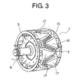
Figure 3 is a perspective that shows a rotor fromFigure 1 ; -
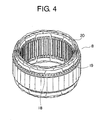
Figure 4 is a perspective that shows a stator fromFigure 1 ; -
Figure 5 is a diagram of a stator core inside a front bracket end ofFigure 1 when viewed from a rear bracket; -
Figure 6 is an explanatory diagram in which a stator core of an alternator according toEmbodiment 2 of the present invention is shown flattened out; and -
Figure 7 is an electrical circuit diagram for the automotive alternator inFigure 6 . - Automotive alternators according to respective preferred embodiments of the present invention will be explained below based on the drawings, and identical or corresponding members and portions in each of the drawings will be given identical numbering.
-
Figure 1 is a cross section that shows an automotive alternator (hereinafter simply "alternator") according toEmbodiment 1 of the present invention, andFigure 2 is a front elevation of the automotive alternator inFigure 1 when viewed from an end near afront bracket 1.
This alternator, which constitutes a dynamoelectric machine, includes: acase 3 that is constituted by afront bracket 1 and arear bracket 2; ashaft 6 that is disposed inside thecase 3 and that has apulley 4 fixed to a first end portion; a Lundellrotor 7 that is fixed to theshaft 6;fans 5 that are fixed to two end surfaces of therotor 7; and astator 8 that is fixed to an inner wall surface of thecase 3.
The alternator also includesslip rings 9 that are fixed to a second end portion of theshaft 6 so as to supply electric current to therotor 7; a pair of brushes 10 that slide on theslip rings 9; abrush holder 11 that houses the brushes 10; arectifier 12 that is electrically connected to thestator 8 so as to rectify alternating current that is generated in thestator 8 into direct current; a heatsink 13 that is fitted into thebrush holder 11; and aregulator 14 that is fixed adhesively to the heatsink 13 and that adjusts magnitude of an alternating-current voltage that arises in thestator 8. - As shown in
Figure 3 , therotor 7 is constituted by: arotor coil 15 that generates magnetic flux on passage of electric current; and a pair ofpole cores 16 that are disposed so as to cover therotor coil 15 and in which magnetic poles are formed by the magnetic flux. The pair of polecores pole cores 16 are made of iron, and are fixed to theshaft 6 such that eight claw-shapedmagnetic poles 17 on each that extend axially at a uniform angular pitch circumferentially face each other so as to intermesh with each other. - As shown in
Figure 4 , thestator 8 includes: astator core 19 that is constituted by a cylindrical laminated core in which a plurality ofslots 18 that extend axially are formed at a predetermined pitch circumferentially; and a stator winding 20 that is installed in thestator core 19.
As shown inFigure 5 , theslots 18 are formed at a uniform pitch circumferentially. - The
front bracket 1, which constitutes a first bracket, and therear bracket 2, which constitutes a second bracket, are each formed integrally by aluminum die casting. Bothbrackets
A pair of front stays 21 and 21 that project radially and that constitute first stays are formed on thefront bracket 1. Arear stay 22 that constitutes a second stay is formed on therear bracket 2 so as to face one of thefront stays 21. A pair of front-end penetrating apertures A1 are formed on the respectivefront stays rear stay 22.
The rear-end penetrating aperture A2 faces one front-end penetrating aperture A1. The alternator is mounted to a vehicle by passing a bolt (not shown) that constitutes a fastening means simultaneously through that front-end penetrating aperture A1, an aperture (not shown) of a vehicle mount portion that constitutes a mount body, and the rear-end penetrating aperture A2 and fastening the bolt, and also by passing a bolt through the remaining front-end penetrating aperture A1 and screwing the bolt directly into the vehicle.
Moreover, thestays stays - Bolt fastening
portions front bracket 1 and therear bracket 2, respectively, so as to be at a uniform angular pitch of 90 degrees circumferentially. Fastening apertures are formed on the respective bolt fasteningportions stator core 19 are placed in contact with end surfaces of thefront bracket 1 and therear bracket 2, respectively, and thestator core 19 is held firmly by thefront bracket 1 and therear bracket 2 by passingbolts 25 through the fastening apertures of the bolt fasteningportions front bracket 1 and therear bracket 2 contact thestator core 19 directly, heat that is generated in thestator core 19 is transferred efficiently to thefront bracket 1 and therear bracket 2. - In an automotive alternator of the above configuration, electric current is supplied from a battery (not shown) through the brushes 10 and the
slip rings 9 to therotor coil 15, generating magnetic flux. Claw-shapedmagnetic poles 17 of onepole core 16 are magnetized into North-seeking (N) poles by this magnetic flux, and claw-shapedmagnetic poles 17 of theother pole core 16 are magnetized into South-seeking (S) poles. At the same time, rotational torque from an engine is transmitted through a belt and thepulley 4 to theshaft 6, rotating therotor 7.
As a result, a rotating magnetic field is applied to the stator winding 20, generating electromotive force in the stator winding. Magnitude of the alternating-current electromotive force is adjusted by theregulator 14, which adjusts current flowing to therotor 7. Alternating current that is generated by the alternating-current electromotive force also passes through therectifier 12 and is rectified into direct current, and the battery is charged. - Now, when an automotive alternator is mounted to a vehicle, displacement of the bracket when vibrations from the engine propagate through the stays to the bracket can normally be kept to a minimum by mounting the alternator such that its center of gravity is placed on a straight line that connects the front-end penetrating apertures A1 that are respectively formed on the
front stays 21.
However, it is often difficult to mount the alternator such that its center of gravity is placed on the above straight line due to layout relationships with other auxiliary machinery that is fixed to the vehicle.
In such cases, when vibrational acceleration that results from engine vibration is applied to the alternator, the largest displacements occur in an axial direction of theshaft 6 at portions that are farthest away from supported points that are constituted by the bolts that pass through the penetrating apertures A1 and A2. - In this embodiment, as shown in
Figure 2 , thefront bracket 1 and therear bracket 2 are disposed at a position where an approximate perpendicular bisector V of a straight line L that connects centers of the pair of penetrating apertures A1 that are formed on thefront stays shaft 6 intersect.
Consequently, because distances that connect the center of gravity G of the alternator and the pair of penetrating apertures A1 above the axis of theshaft 6 are equal and the loads that act on thestays stays stays
The bolt fasteningportions stator core 19 is held by thefront bracket 1 and therear bracket 2 by fastening thebolts 25 at these bolt fasteningportions
InFigure 2 , the bolt fasteningportions shaft 6 from the straight line L that connects the centers of the pair of penetrating apertures A1 are portions that are displaced furthest in an axial direction of theshaft 6, which is vertical relative to the surface of the page, but because thestator core 19 is held by and integrated firmly with thefront bracket 1 and therear bracket 2 by thebolts 25 at these portions, resistance to vibrations from the engine at the portions of thebracket stator core 19 is improved.
In other words, vibrations from the engine propagate to thebracket stays bracket stator core 19 that results from the vibrations is suppressed, enabling amplification of magnetostriction to be suppressed and the generation of unpleasant magnetic noise to be prevented. - Vibrations are generated when the
rotor 7 of the alternator rotates at high speed due to radial imbalances in therotor 7 and the mass of therotor 7, but because vibration resistance at the above portions that are held between thefront bracket 1 and therear bracket 2 is improved, it is not necessary to completely eliminate radial imbalances in therotor 7, making high-precision adjustment of imbalances in therotor 7 unnecessary.
Because thestator core 19 is held and fixed firmly, displacement of thestator core 19 is suppressed even if vibrations from the engine and vibrations due to imbalances in therotor 7 do occur, and thestator core 19 and thebrackets stator core 19 to be transferred efficiently to thebrackets - In addition, because the center of gravity G of the alternator (on the axis of the shaft 6) is to the right of the straight line L in
Figure 2 , torque acts on thestator core 19 in a clockwise direction, but because the bolt fasteningportions portions 23 are disposed near the center of gravity G and also away from the center of gravity G, thestator core 19 is held firmly between and by thefront bracket 1 and therear bracket 2 by means of thebolts 25 at the bolt fasteningportions 23, also suppressing circumferential displacement of thestator core 19. Consequently, magnetic noise is further reduced. - In addition, because the stays 21 and 22 are disposed such that a line that extends radially through the center of gravity G of the alternator passes through an intermediate point (Y1 = Y2) of the distance between the
stays -
Figure 6 is an explanatory diagram in which astator core 50 of an alternator according toEmbodiment 2 of the present invention is shown flattened out, andFigure 7 is an electrical circuit diagram for this alternator.
An alternator according to this embodiment is an alternator in which the number of slots is two slots per phase per pole, specifically, the number of slots is 72 and the number of magnetic poles is twelve poles.
In astator core 50 according to this embodiment, a first three-phase stator winding 51A and a second three-phase stator winding 51 B are installed, in which conducting wires are wound so as to have a phase difference of 32.5 electrical degrees. Thisstator core 50 is constituted by: an annular core back 52; andwide teeth 53A andnarrow teeth 53B that extend radially inward from the core back 52.
Slots 54 of thestator core 50 are formed by disposing thewide teeth 53A and thenarrow teeth 53B alternately. Theslots 54 are formed such that pitches C1 and C2 between center lines of opening portions that extend radially alternate repeatedly between 5.42 mechanical degrees and 4.58 mechanical degrees.Bolts 25 that are positioned on an approximate perpendicular bisector V of a straight line L that connects centers of a pair of penetrating apertures A1 are disposed on radial center lines of thewide teeth 53A.
The rest of the configuration is similar to that ofEmbodiment 1. - In this embodiment, because the pitches C1 and C2 between the center lines of each of the
slots 54 are formed so as to be nonuniform, 12f components of magnetic vibrational force, which are harmonics that are extremely unpleasant to the ear, are canceled out as described in Japanese Patent No.3,490,659
Because thebolts 25, which are fastened inbolt fastening portions 23 that displace maximally in an axial direction of theshaft 6 on a perpendicular bisector V, are disposed on radial center lines of the very rigidwide teeth 53A, thestator core 19 can be held firmly by thebrackets - Moreover, in this embodiment, an alternator in which the number of slots is 72 and the number of magnetic poles is twelve poles has been explained, but a generator in which the number of slots is 96 and the number of magnetic poles is sixteen poles, or a generator in which the number of slots is 120 and the number of magnetic poles is twenty poles may also be used.
A generator in which the number of slots is three per phase per pole may also be used.
In each of the above embodiments, an automotive alternator in which a pair ofstays front bracket 1 and asingle stay 22 was formed on therear bracket 2 has been explained, but the present invention can also be applied to an alternator in which a pair of stays are formed on the rear bracket.
In addition, the generator is not limited to automotive use, and the present invention can also be applied to electric motors, which are also dynamoelectric machines.
Claims (4)
- A dynamoelectric machine comprising:a shaft;a rotor that is fixed to said shaft;a stator that has a stator core that is disposed so as to surround an outer circumference of said rotor and in which a plurality of slots that extend axially are formed so as to be spaced apart circumferentially; anda first bracket and a second bracket that hold circumferential edge portions of said stator core from two axial ends using a plurality of holding means and that envelope said stator core,a pair of first stays that are formed on said first bracket being fixed to a mount body by a fastening means that penetrates through a pair of penetrating apertures that are respectively formed on said first stays,said dynamoelectric machine being characterized in that:said pair of penetrating apertures are formed at positions such that an approximate perpendicular bisector of a straight line that connects centers of said penetrating apertures intersects an axis of said shaft; andone of said holding means is disposed on said perpendicular bisector near said shaft.
- A dynamoelectric machine according to Claim 1, characterized in that said holding means are disposed at a uniform angular pitch circumferentially.
- A dynamoelectric machine according to either of Claims 1 or 2, characterized in that said first bracket and said second bracket are disposed at a position such that an approximate perpendicular bisector of said penetrating apertures that are formed on said first stays that is constituted by a straight line that joins penetrating apertures that are formed on second stays that face said penetrating apertures intersects a center of gravity of said dynamoelectric machine.
- A dynamoelectric machine according to any one of Claims 1 through 3, characterized in that:said stator core is formed such that said slots are greater than or equal to two slots per phase per pole in number, and pitches between radial center lines of opening portions of respective adjacent slots are formed at a nonuniform pitch by changing circumferential width dimensions of teeth that define said slots; andsaid holding means that is disposed on said perpendicular bisector near said shaft is disposed on a radial center line of a wide tooth.
Applications Claiming Priority (1)
| Application Number | Priority Date | Filing Date | Title |
|---|---|---|---|
| PCT/JP2007/056043 WO2008117376A1 (en) | 2007-03-23 | 2007-03-23 | Rotary electric machine |
Publications (3)
| Publication Number | Publication Date |
|---|---|
| EP2131476A1 true EP2131476A1 (en) | 2009-12-09 |
| EP2131476A4 EP2131476A4 (en) | 2017-03-01 |
| EP2131476B1 EP2131476B1 (en) | 2021-04-21 |
Family
ID=39788121
Family Applications (1)
| Application Number | Title | Priority Date | Filing Date |
|---|---|---|---|
| EP07739484.9A Ceased EP2131476B1 (en) | 2007-03-23 | 2007-03-23 | Rotary electric machine |
Country Status (5)
| Country | Link |
|---|---|
| US (1) | US9225219B2 (en) |
| EP (1) | EP2131476B1 (en) |
| JP (1) | JPWO2008117376A1 (en) |
| CN (1) | CN101432950B (en) |
| WO (1) | WO2008117376A1 (en) |
Cited By (1)
| Publication number | Priority date | Publication date | Assignee | Title |
|---|---|---|---|---|
| EP3379699A4 (en) * | 2015-11-20 | 2018-12-05 | Mitsubishi Electric Corporation | Rotating electric device |
Families Citing this family (2)
| Publication number | Priority date | Publication date | Assignee | Title |
|---|---|---|---|---|
| CN106385127B (en) * | 2016-09-29 | 2020-05-22 | 珠海格力电器股份有限公司 | Motor and motor driving device |
| US12341402B2 (en) * | 2022-01-20 | 2025-06-24 | Schaeffler Technologies AG & Co. KG | Emotor rotor centering and shipping aid with annular disk and bolt holes |
Family Cites Families (12)
| Publication number | Priority date | Publication date | Assignee | Title |
|---|---|---|---|---|
| US917188A (en) * | 1904-11-19 | 1909-04-06 | Gen Electric | Dynamo-electric machine. |
| JPS5150404A (en) * | 1974-10-30 | 1976-05-04 | Hitachi Ltd | |
| DE2845667A1 (en) * | 1978-10-20 | 1980-05-08 | Bosch Gmbh Robert | ELECTRIC MACHINE |
| JP2924689B2 (en) | 1994-06-20 | 1999-07-26 | 株式会社デンソー | Generator |
| US5705870A (en) * | 1995-10-19 | 1998-01-06 | Thomsen; Bradley E. | Universally mountable automotive alternator |
| JP3229543B2 (en) * | 1996-03-29 | 2001-11-19 | 三菱電機株式会社 | Casting mold for bracket of automotive alternator |
| JP3351690B2 (en) * | 1996-08-26 | 2002-12-03 | 三菱電機株式会社 | Vehicle alternator and method of assembling the same |
| JP3490659B2 (en) * | 2000-02-29 | 2004-01-26 | 三菱電機株式会社 | AC generator |
| JP2002136032A (en) * | 2000-10-23 | 2002-05-10 | Denso Corp | Electric rotating machine for vehicles |
| US6504280B2 (en) * | 2001-02-28 | 2003-01-07 | Lawrence G. Trowbridge | Adjustable attachment alternator |
| JP2005269756A (en) | 2004-03-18 | 2005-09-29 | Denso Corp | Rotating electric machine |
| JP4297070B2 (en) | 2005-03-23 | 2009-07-15 | 株式会社デンソー | Vehicle alternator |
-
2007
- 2007-03-23 CN CN2007800152623A patent/CN101432950B/en not_active Expired - Fee Related
- 2007-03-23 JP JP2007522332A patent/JPWO2008117376A1/en active Pending
- 2007-03-23 US US12/093,568 patent/US9225219B2/en not_active Expired - Fee Related
- 2007-03-23 EP EP07739484.9A patent/EP2131476B1/en not_active Ceased
- 2007-03-23 WO PCT/JP2007/056043 patent/WO2008117376A1/en not_active Ceased
Non-Patent Citations (1)
| Title |
|---|
| See references of WO2008117376A1 * |
Cited By (2)
| Publication number | Priority date | Publication date | Assignee | Title |
|---|---|---|---|---|
| EP3379699A4 (en) * | 2015-11-20 | 2018-12-05 | Mitsubishi Electric Corporation | Rotating electric device |
| US10644560B2 (en) | 2015-11-20 | 2020-05-05 | Mitsubishi Electric Corporation | Rotary electric machine |
Also Published As
| Publication number | Publication date |
|---|---|
| EP2131476B1 (en) | 2021-04-21 |
| US20100176684A1 (en) | 2010-07-15 |
| JPWO2008117376A1 (en) | 2010-07-08 |
| CN101432950B (en) | 2012-11-21 |
| US9225219B2 (en) | 2015-12-29 |
| EP2131476A4 (en) | 2017-03-01 |
| WO2008117376A1 (en) | 2008-10-02 |
| CN101432950A (en) | 2009-05-13 |
Similar Documents
| Publication | Publication Date | Title |
|---|---|---|
| EP1024579B1 (en) | Alternator | |
| US8497615B2 (en) | Rotary electric machine | |
| JP2009148057A (en) | AC generator for vehicles | |
| EP1030433B1 (en) | Dynamo-electric machine | |
| US6433456B1 (en) | Automotive alternator | |
| JP3368605B2 (en) | Stator of vehicle alternator | |
| EP1981154B1 (en) | Dynamo-electric machine | |
| US20050006978A1 (en) | Twin coil claw pole rotor with stator phase shifting for electrical machine | |
| US8546994B2 (en) | Dynamoelectric machine | |
| EP2131476B1 (en) | Rotary electric machine | |
| CN112075015B (en) | Centrifugal fans and automotive alternators | |
| EP1128521B1 (en) | Alternator with non-uniform slot openings | |
| JP4975165B2 (en) | Rotating electric machine for vehicles | |
| JP5495945B2 (en) | Rotating electric machine | |
| EP1109300B1 (en) | Automotive alternator | |
| US20050006973A1 (en) | Twin coil claw pole rotor with five-phase stator winding for electrical machine | |
| US20230036949A1 (en) | End shield for a rotary electric machine | |
| JPH0951646A (en) | Electric rotating machine for vehicles | |
| KR100268099B1 (en) | Rotary electric machine for vehicle | |
| US20240162764A1 (en) | Rotary electric machine | |
| JP2014112983A (en) | Rotary electric machine | |
| CN116868480A (en) | Rotating motor |
Legal Events
| Date | Code | Title | Description |
|---|---|---|---|
| PUAI | Public reference made under article 153(3) epc to a published international application that has entered the european phase |
Free format text: ORIGINAL CODE: 0009012 |
|
| 17P | Request for examination filed |
Effective date: 20080424 |
|
| AK | Designated contracting states |
Kind code of ref document: A1 Designated state(s): AT BE BG CH CY CZ DE DK EE ES FI FR GB GR HU IE IS IT LI LT LU LV MC MT NL PL PT RO SE SI SK TR |
|
| DAX | Request for extension of the european patent (deleted) | ||
| RA4 | Supplementary search report drawn up and despatched (corrected) |
Effective date: 20170130 |
|
| RIC1 | Information provided on ipc code assigned before grant |
Ipc: H02K 5/26 20060101ALI20170124BHEP Ipc: H02K 5/00 20060101ALI20170124BHEP Ipc: H02K 5/24 20060101AFI20170124BHEP |
|
| STAA | Information on the status of an ep patent application or granted ep patent |
Free format text: STATUS: EXAMINATION IS IN PROGRESS |
|
| 17Q | First examination report despatched |
Effective date: 20170808 |
|
| GRAP | Despatch of communication of intention to grant a patent |
Free format text: ORIGINAL CODE: EPIDOSNIGR1 |
|
| STAA | Information on the status of an ep patent application or granted ep patent |
Free format text: STATUS: GRANT OF PATENT IS INTENDED |
|
| INTG | Intention to grant announced |
Effective date: 20201215 |
|
| RBV | Designated contracting states (corrected) |
Designated state(s): DE FR |
|
| GRAS | Grant fee paid |
Free format text: ORIGINAL CODE: EPIDOSNIGR3 |
|
| GRAA | (expected) grant |
Free format text: ORIGINAL CODE: 0009210 |
|
| STAA | Information on the status of an ep patent application or granted ep patent |
Free format text: STATUS: THE PATENT HAS BEEN GRANTED |
|
| AK | Designated contracting states |
Kind code of ref document: B1 Designated state(s): DE FR |
|
| REG | Reference to a national code |
Ref country code: DE Ref legal event code: R096 Ref document number: 602007061070 Country of ref document: DE |
|
| REG | Reference to a national code |
Ref country code: DE Ref legal event code: R097 Ref document number: 602007061070 Country of ref document: DE |
|
| PLBE | No opposition filed within time limit |
Free format text: ORIGINAL CODE: 0009261 |
|
| STAA | Information on the status of an ep patent application or granted ep patent |
Free format text: STATUS: NO OPPOSITION FILED WITHIN TIME LIMIT |
|
| 26N | No opposition filed |
Effective date: 20220124 |
|
| PGFP | Annual fee paid to national office [announced via postgrant information from national office to epo] |
Ref country code: DE Payment date: 20220203 Year of fee payment: 16 |
|
| PGFP | Annual fee paid to national office [announced via postgrant information from national office to epo] |
Ref country code: FR Payment date: 20220209 Year of fee payment: 16 |
|
| REG | Reference to a national code |
Ref country code: DE Ref legal event code: R119 Ref document number: 602007061070 Country of ref document: DE |
|
| PG25 | Lapsed in a contracting state [announced via postgrant information from national office to epo] |
Ref country code: FR Free format text: LAPSE BECAUSE OF NON-PAYMENT OF DUE FEES Effective date: 20230331 Ref country code: DE Free format text: LAPSE BECAUSE OF NON-PAYMENT OF DUE FEES Effective date: 20231003 |