EP2131461A1 - Spark plug, and its manufacturing method - Google Patents
Spark plug, and its manufacturing method Download PDFInfo
- Publication number
- EP2131461A1 EP2131461A1 EP08738981A EP08738981A EP2131461A1 EP 2131461 A1 EP2131461 A1 EP 2131461A1 EP 08738981 A EP08738981 A EP 08738981A EP 08738981 A EP08738981 A EP 08738981A EP 2131461 A1 EP2131461 A1 EP 2131461A1
- Authority
- EP
- European Patent Office
- Prior art keywords
- region
- ground electrode
- thickness
- spark plug
- end portion
- Prior art date
- Legal status (The legal status is an assumption and is not a legal conclusion. Google has not performed a legal analysis and makes no representation as to the accuracy of the status listed.)
- Granted
Links
Images




Classifications
-
- H—ELECTRICITY
- H01—ELECTRIC ELEMENTS
- H01T—SPARK GAPS; OVERVOLTAGE ARRESTERS USING SPARK GAPS; SPARKING PLUGS; CORONA DEVICES; GENERATING IONS TO BE INTRODUCED INTO NON-ENCLOSED GASES
- H01T13/00—Sparking plugs
- H01T13/20—Sparking plugs characterised by features of the electrodes or insulation
- H01T13/32—Sparking plugs characterised by features of the electrodes or insulation characterised by features of the earthed electrode
-
- H—ELECTRICITY
- H01—ELECTRIC ELEMENTS
- H01T—SPARK GAPS; OVERVOLTAGE ARRESTERS USING SPARK GAPS; SPARKING PLUGS; CORONA DEVICES; GENERATING IONS TO BE INTRODUCED INTO NON-ENCLOSED GASES
- H01T21/00—Apparatus or processes specially adapted for the manufacture or maintenance of spark gaps or sparking plugs
- H01T21/02—Apparatus or processes specially adapted for the manufacture or maintenance of spark gaps or sparking plugs of sparking plugs
-
- Y—GENERAL TAGGING OF NEW TECHNOLOGICAL DEVELOPMENTS; GENERAL TAGGING OF CROSS-SECTIONAL TECHNOLOGIES SPANNING OVER SEVERAL SECTIONS OF THE IPC; TECHNICAL SUBJECTS COVERED BY FORMER USPC CROSS-REFERENCE ART COLLECTIONS [XRACs] AND DIGESTS
- Y10—TECHNICAL SUBJECTS COVERED BY FORMER USPC
- Y10T—TECHNICAL SUBJECTS COVERED BY FORMER US CLASSIFICATION
- Y10T29/00—Metal working
- Y10T29/49—Method of mechanical manufacture
- Y10T29/49002—Electrical device making
- Y10T29/49082—Resistor making
- Y10T29/49083—Heater type
Definitions
- the present invention relates to a spark plug for use in an automotive internal combustion engine etc. and a manufacturing method thereof.
- a spark plug which includes a center electrode and a ground electrode arranged at a discharge gap away from a front end portion of the center electrode so as to generate a spark discharge between the center electrode and the ground electrode for ignition of an air-fuel mixture in a combustion chamber of an internal combustion engine.
- One known type of spark plug with improved ignition performance includes a center electrode having a noble metal tip welded to an electrode body thereof and a ground electrode having a protruding region formed by e.g. welding a cylindrical noble metal tip, with an annular surface of the cylindrical noble metal tip directly facing the noble metal tip of the center electrode, so as to generate a spark discharge between these noble metal tips.
- a ground electrode has a protruding region formed by press forming.
- the spark plug attains improved ignition performance but has a problem of increase in manufacturing cost due to the use of the expensive noble metal tip.
- the protruding region of the ground electrode is formed by press forming
- the press forming process causes plastic deformation in the ground electrode so that the ground electrode becomes susceptible to breakage. This results in an increased possibility that the ground electrode will break when bent to a substantially L-shaped form during the manufacturing of the spark plug or when subjected to external force during the use of the finished plug product.
- the spark plug thus has a problem of difficulty in securing durability.
- the present invention has been made to solve the above problems. It is an object of the present invention to provide a spark plug that combines good ignition performance, economy and durability.
- a spark plug comprising: a cylindrical metal shell; a cylindrical ceramic insulator retained in the metal shell; a center electrode retained in the ceramic insulator and extending in an axial direction; and a ground electrode formed into a bent shape and having a rear end portion fixed to the metal shell and a front end portion facing a front end portion of the center electrode with a gap left between the front end portion of the ground electrode and the front end portion of the center electrode, the ground electrode including a large thickness region formed on a rear end side thereof with a large thickness, a small thickness region formed on a front end side thereof with a smaller thickness than that of the large thickness region, a protruding region formed on the small thickness region and facing the center electrode and a thickness changing region formed between the large thickness region and the small thickness region and located at a different position from a position of a minimum curvature radius region of the bent shape of the ground electrode.
- a manufacturing method of a spark plug including: a cylindrical metal shell; a cylindrical ceramic insulator retained in the metal shell; a center electrode retained in the ceramic insulator and extending in an axial direction; and a ground electrode formed into a bent shape and having a rear end portion fixed to the metal shell and a front end portion facing a front end portion of the center electrode with a gap left between the front end portion of the ground electrode and the front end portion of the center electrode, the ground electrode including a large thickness region formed on a rear end side thereof with a large thickness, a small thickness region formed on a front end side thereof with a smaller thickness than that of the large thickness region, a protruding region formed on the small thickness region and facing the center electrode and a thickness changing region formed between the large thickness region and the small thickness region and located at a different position from a position of a minimum curvature radius region of the bent shape of the ground electrode, the manufacturing method comprising: a press forming step for
- the ground electrode has its thickness changing region formed between the large thickness region and the small thickness region in such a manner that the thickness changing region differs in position from the minimum curvature radius region of the bent shape of the ground electrode. It is therefore possible to prevent the occurrence of a breakage in the ground electrode and secure durability.
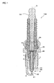
- a spark plug 100 includes a metal shell 1, a ceramic insulator 2, a center electrode 3 and a ground electrode 4.
- the metal shell 1 is made of metal such as low carbon steel and formed into a cylindrical shape.
- a threaded portion 7 is formed on an outer circumferential surface of the metal shell 11 and adapted for mounting the spark plug 100 onto an engine block (not shown).
- the ceramic insulator 2 is made of sintered ceramic such as alumina or aluminum nitride and retained in the metal shell 11 with a front end portion of the ceramic insulator 2 protruding from an end face of the metal shell 1.
- a through hole 6 is formed through the ceramic insulator 2 in the direction of an axis O.
- the center electrode 3 is arranged in a front side (bottom side in the drawing) of the through hole 6 with a front end portion of the center electrode 3 protruding from an end face of the ceramic insulator 2.
- This center electrode 3 has a center electrode body 30 as a surface layer part and a noble metal tip 32 welded to a front end of the center electrode body 30.
- the center electrode body 30 is made of Ni-based alloy and formed into a cylindrical column shape.
- the center electrode 30 also has a thermal conduction enhancing member of Cu or Cu alloy embedded in the electrode body 30.
- the noble metal tip 3 can be made of Ir alloy containing Ir as a main component and 3 to 50 mass% of one or more selected from Pt, Rh, Ru and Re in total as a sub-component to not only limit oxidation/volatilization of Ir but obtain improvement in workability and have a cylindrical column outer shape with a diameter of 0.6 mm.
- a terminal fitting 23 is arranged in a rear side of the though hole 6 of the ceramic insulator 2 and electrically connected to the center electrode 3 via a radio noise reducing resistor 25 and conductive glass seal layers 24 and 26.
- the ground electrode 4 is bent to a substantially L-shaped form and arranged to have one end portion (rear end portion) thereof joined to the front end face of the metal shell 1 and the other end portion (front end portion) facing a front end of the noble metal tip 32 of the center electrode 3.
- this ground electrode 4 includes a large thickness region 44 formed on a rear end side thereof with a large thickness (plate thickness in a direction perpendicular to a longitudinal direction of the ground electrode 4), a small thickness region 45 formed on a front end side thereof with a smaller thickness than that of the large thickness region 44 and a column-shaped protruding region 41 formed on the small thickness region 45 so as to face and protrude toward the noble metal tip 32.
- the protruding region 41 has a cylindrical column outer shape with a diameter of 1.0 mm and a height of 0.3 mm.
- the ground electrode 4 including the protruding region 41 can be made of e.g. Ni-based alloy.
- the column-shaped protruding region 41 is formed by press forming as will be explained later.
- the ground electrode 4 further includes a thickness changing region 42 formed between the large thickness region 44 and the small thickness region 45 during the press forming process and located at a different position from a position of a minimum curvature radius region 43 in which the bent shape of the ground electrode 4 has a minimum radius of curvature as shown in FIG. 2 .
- the thickness changing region 42 is formed on the front end side of the ground electrode 4 with respect to the minimum curvature radius region 43, it is preferable that the thickness changing region 42 has a front end side (small thickness region side) facing a shoulder portion 33 of the center electrode 3 in the direction of the axis O and a rear end side (large thickness region side) facing the front end face of the ceramic insulator 2 in the direction of the axis O.
- a part of the thickness changing region 42 is located at a position overlapping the shoulder portion 33 of the center electrode 3 in the direction of the axis O.
- the column-shaped protruding region 41 is formed by press forming on the ground electrode 4 so as to face the noble metal tip 32 as mentioned above.
- This protruding region 41 performs the same function as a noble metal tip provided on the ground electrode 4. It is thus possible to provide improvement in ignition performance. It is also possible to avoid the necessity for the expensive noble metal tip and the laser welding process and provide substantial reduction in manufacturing cost as compared with the case of laser welding the noble metal tip to the ground electrode 4.
- the center electrode 3 may alternatively have no noble metal tip 32 for further reduction in manufacturing cost.
- the center electrode 3 and the protruding region 41 can be cylindrical column-shaped with a diameter of 2.5 mm and 2.9 mm, respectively.
- a noble metal tip 46 of e.g. Pt alloy can be further provided on the column-shaped protruding region 41 of the ground electrode 4.
- This configuration reduces the volume (amount) of the noble metal tip required as compared with the case of providing the noble metal tip directly on the flat ground electrode 4 without the column-shaped protruding region 41. It is thus possible to provide not only improvements in ignition performance and durability but reduction in manufacturing cost.
- the noble metal tip 46 and the protruding region 41 of the ground electrode 4 are joined together by laser welding. More specifically, the noble metal tip 46 is first placed on the protruding region 41.
- the boundary of the protruding region 41 and the noble metal tip 46 is subsequently irradiated with a laser, thereby forming a fused region 47 in which constituent materials of the protruding region 41 and the noble metal tip 46 are fused together to join the protruding region 41 and the noble metal tip 46.
- D1 is an outer diameter of the noble metal tip 46
- L1 is a height of the noble metal tip 46
- P is a height of protrusion of the noble metal tip 46 from the fused region 47
- D2 is an outer diameter of the protruding region 41
- L2 is a height of the protruding region 41.
- the outer diameter D1 of the noble metal tip 46 is set smaller than the outer diameter D2 of the protruding region 41 (D 1 ⁇ D2), it is possible to provide improvement in ignition performance while increasing the welding strength between the noble metal tip 46 and the protruding region 41. Moreover, it is possible to ensure a sufficient width of the fused region 47, secure a sufficient height P of protrusion of the noble metal tip 46 from the fused region 47 and thereby provide further improvements in ignition performance and welding strength of the protruding region 41 and the noble metal tip 46 when each of the height L1 of the noble metal tip 46 and the height P of protrusion of the noble metal tip 46 from the fused region 47 is set larger than the height L2 of the protruding region 41 (L1 > L2, P > L2).
- the outer diameter D1 of the noble metal tip 46, the height L1 of the noble metal tip 46, the protrusion height P of the noble metal tip 46 from the fused region 47, the outer diameter D2 of the protruding region 41 and the height L2 of the protruding region 41 can be set to 0.7 mm, 0.6 mm, 0.4 mm, 1.2 mm and 0.3 mm, respectively.
- a noble metal tip 460 with a recess in a bottom thereof may be used by fitting the column-shaped protruding region 41 in the recess of the noble metal tip 460 as shown in FIG. 4 .
- an annular noble metal tip 461 with a center circular hole may alternatively be used by fitting the column-shaped protruding region 41 in the circular hole of the noble metal tip 461.
- the thickness changing region 42 and the minimum curvature radius region 43 are located at the different positions in the spark plug 100 as mentioned above. With this location, it is possible to prevent the ground electrode 4 from breaking when the ground electrode 4 is bent to a substantially L-shaped form during the manufacturing process and from breaking by external force or vibrations when the finished product is mounted to and used in an automotive engine etc.
- the periphery of the protruding region decreases in thickness to inevitably define the thickness changing region 42 between the pressed part and the unpressed part.
- the minimum curvature radius region 43 is most stressed and susceptible to breakage in the ground electrode 4. If the minimum curvature radius region 43 and the thickness changing region 42 coincide in position with each other, it is more likely that the breakage will occur in the ground electrode 4. It is however possible to prevent the ground electrode 4 from readily breaking when the minimum curvature radius region 43 and the thickness changing region 42 differ in position from each other.
- the thickness changing region 42 is located on the front end side of the ground electrode 4 with respect to the minimum curvature radius region 43 as shown in FIG. 2 .
- the thickness changing region 42 may alternatively be located on the rear end side (metal shell side) of the ground electrode 4 with respect to the minimum curvature radius region 43 as shown in FIG. 6 .
- the large thickness region 44 has a front end edge 44c (i.e. edge between the thickness changing region 42 and the large thickness region 44) situated rearward of the front end of the ceramic insulator 2 in the direction of the axis O.
- a gap G1 between the protruding region 41 and the noble metal tip a gap G2 between the front end edge 44c of the large thickness region 44 and the ceramic insulator 2 and a gap G3 between the front end edge 44c of the large thickness region 44 and the center electrode 3 along a surface of the ceramic insulator 2 so as to satisfy a relationship of G2 ⁇ G1 ⁇ G3 and thereby allow the front end edge 44c of the large thickness region 44 to serve as a surface creepage portion for cleaning.
- the thickness of the thickness changing region 42 of the ground electrode 4 changes gradually and smoothly so that the thickness changing region 42 has a tapered cross section in the direction of the axis O.
- the ground electrode 4 may alternatively be provided with a thickness changing region 42 whose thickness changes gradually and smoothly such that the thickness changing region 42 has a curved cross section in the axis direction as shown in FIG. 7 .
- the ground electrode 4 increases in hardness by work hardening during the press forming process and thus becomes difficult to bend, it is feasible, after the press forming process, to anneal the ground electrode 4 for ease of the subsequent process of bending the ground electrode 4 to a substantially L-shaped form.
- the ground electrode 4 is annealed before welded to the metal shell 1, only the ground electrode 4 can be subjected to annealing. This makes it possible to manufacture the spark plug 100 more efficiently for reduction in manufacturing cost.
- the form of the column-shaped protruding region 41 is not particularly restricted, it is preferable that the protruding region 41 has a cross section area of 0.1 mm 2 to 6.6 mm 2 in a direction perpendicular to the axis direction for compatibility between ignition performance and durability.
- a cylindrical column-shaped protruding region 410 is formed on the front end portion of the ground electrode 4 with both of lateral corners of the front end of the ground electrode 4 being cut away.
- a square column-shaped protruding region 411 is formed on the front end portion of the ground electrode 4.
- a triangular column-shaped protruding region 412 is formed on the front end portion of the ground electrode 4.
- a protruding region 415 is provided in the form of a star-shaped column at a position slightly rearward from the front end edge of the ground electrode 4.
- an elliptic cylinder-shaped protruding region 416 is formed at a position slightly rearward from the front end edge of the ground electrode 4.
- a cylindrical column-shaped protruding region 417 having a circular depression in the center thereof is formed at a position slightly rearward from the front end edge of the ground electrode 4.
- a ground electrode 400 having a ground electrode body 404 and a thermal conduction enhancing member (high thermal conduction member) 500 of Cu or Cu alloy embedded in the electrode body 404 as shown in FIG. 16 .
- the ground electrode thermal conduction enhancing member 500 extends from a large thickness region 444 to a position of a protruding region 441 on a small thickness region 445 through a thickness changing region 422 of the ground electrode 400.
- the ground electrode thermal conduction enhancing member 500 extends to and exists in the small thickness region 445, it is possible to enable efficient thermal conduction of the small thickness region 445 and limit consumption of the protruding region 441 and the noble metal tip 446 joined to the protruding region 441.
- a part 545 of the ground electrode thermal conduction enhancing member 500 existing in the small thickness region 445 is made smaller in thickness than a part 544 of the ground electrode thermal conduction enhancing member 500 existing in the large thickness region 444. It is thus possible to minimize the mechanical strength deterioration effect caused by embedding the high thermal conduction member 500 and secure not only efficient thermal conduction but also mechanical strength.
- the spark plug 100 of the present invention combines good ignition performance, economy and durability.
Landscapes
- Engineering & Computer Science (AREA)
- Manufacturing & Machinery (AREA)
- Spark Plugs (AREA)
Abstract
Description
- The present invention relates to a spark plug for use in an automotive internal combustion engine etc. and a manufacturing method thereof.
- A spark plug is known which includes a center electrode and a ground electrode arranged at a discharge gap away from a front end portion of the center electrode so as to generate a spark discharge between the center electrode and the ground electrode for ignition of an air-fuel mixture in a combustion chamber of an internal combustion engine.
- Amid recent calls for global environmental protection, it is more strongly demanded to provide energy savings, regulate emissions of carbon dioxide and reduce emissions of unburned gases (hydrocarbon compounds). In order to satisfy these demands, developments are being actively made in internal combustion engines such as lean-bum engine, direct gasoline-injection engine and low emission gas engine. Further, exhaust gas recirculation (EGR) systems, which recirculate a part of exhaust gases into combustion chambers to reduce negative engine loads in intake strokes and produce more cleaner exhaust emissions, are being actively introduced into the lean-bum engines. Under such circumstances, it is required that the spark plug ignites a lean air-fuel mixture containing a large amount of inert exhaust gases. Spark plugs with higher ignition performance are thus needed.
- One known type of spark plug with improved ignition performance includes a center electrode having a noble metal tip welded to an electrode body thereof and a ground electrode having a protruding region formed by e.g. welding a cylindrical noble metal tip, with an annular surface of the cylindrical noble metal tip directly facing the noble metal tip of the center electrode, so as to generate a spark discharge between these noble metal tips. There is proposed another type of spark plug in which a ground electrode has a protruding region formed by press forming. (See
Patent Document 1.) - Patent Document 1: Japanese Laid-Open Patent Publication No.
2006-286469 - In the case where the protruding region is formed by welding the noble metal tip to the ground electrode, the spark plug attains improved ignition performance but has a problem of increase in manufacturing cost due to the use of the expensive noble metal tip. In the case where the protruding region of the ground electrode is formed by press forming, the press forming process causes plastic deformation in the ground electrode so that the ground electrode becomes susceptible to breakage. This results in an increased possibility that the ground electrode will break when bent to a substantially L-shaped form during the manufacturing of the spark plug or when subjected to external force during the use of the finished plug product. The spark plug thus has a problem of difficulty in securing durability.
- The present invention has been made to solve the above problems. It is an object of the present invention to provide a spark plug that combines good ignition performance, economy and durability.
- According to an aspect of the present invention, there is provided a spark plug, comprising: a cylindrical metal shell; a cylindrical ceramic insulator retained in the metal shell; a center electrode retained in the ceramic insulator and extending in an axial direction; and a ground electrode formed into a bent shape and having a rear end portion fixed to the metal shell and a front end portion facing a front end portion of the center electrode with a gap left between the front end portion of the ground electrode and the front end portion of the center electrode, the ground electrode including a large thickness region formed on a rear end side thereof with a large thickness, a small thickness region formed on a front end side thereof with a smaller thickness than that of the large thickness region, a protruding region formed on the small thickness region and facing the center electrode and a thickness changing region formed between the large thickness region and the small thickness region and located at a different position from a position of a minimum curvature radius region of the bent shape of the ground electrode.
- According to another aspect of the present invention, there is provided a manufacturing method of a spark plug, the spark plug including: a cylindrical metal shell; a cylindrical ceramic insulator retained in the metal shell; a center electrode retained in the ceramic insulator and extending in an axial direction; and a ground electrode formed into a bent shape and having a rear end portion fixed to the metal shell and a front end portion facing a front end portion of the center electrode with a gap left between the front end portion of the ground electrode and the front end portion of the center electrode, the ground electrode including a large thickness region formed on a rear end side thereof with a large thickness, a small thickness region formed on a front end side thereof with a smaller thickness than that of the large thickness region, a protruding region formed on the small thickness region and facing the center electrode and a thickness changing region formed between the large thickness region and the small thickness region and located at a different position from a position of a minimum curvature radius region of the bent shape of the ground electrode, the manufacturing method comprising: a press forming step for providing the ground electrode with the large thickness region, the small thickness region, the thickness changing region and the protruding region; a bending step for bending the ground electrode to define the minimum curvature radius region in such a manner that the minimum curvature radius region and the thickness changing region differ in position from each other; and a front end shaping step for, after the press forming step, processing the front end portion of the ground electrode into a given shape.
- In the spark plug of the present invention, the ground electrode has its thickness changing region formed between the large thickness region and the small thickness region in such a manner that the thickness changing region differs in position from the minimum curvature radius region of the bent shape of the ground electrode. It is therefore possible to prevent the occurrence of a breakage in the ground electrode and secure durability.
-
-
FIG. 1 is a general section view of a spark plug according to one embodiment of the present invention. -
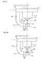
FIG. 2 is an enlarged view of substantial part of the spark plug ofFIG 1 . -
FIG. 3A is an enlarged view of substantial part of a spark plug according to another embodiment of the present invention. -
FIG. 3B is a section view of a ground electrode of the spark plug ofFIG. 3A . -
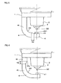
FIG. 4 is an enlarged view of substantial part of a spark plug according to still another embodiment of the present invention. -
FIG. 5 is an enlarged view of substantial part of a spark plug according to yet another embodiment of the present invention. -
FIG. 6 is an enlarged view of substantial part of a spark plug according to a further embodiment of the present invention. -
FIG. 7 is an enlarged view of substantial part of a spark plug according to a still further embodiment of the present invention. -
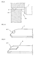
FIG. 8 is a schematic view showing a manufacturing method for the spark plug ofFIG. 1 . -
FIG. 9 is a schematic view showing a manufacturing method for the spark plug ofFIG. 7 . -
FIG. 10 is a modification of a ground electrode protruding region of the spark plug according to the embodiment of the present invention. -
FIG. 11 is a modification of a ground electrode protruding region of the spark plug according to the embodiment of the present invention. -
FIG. 12 is a modification of a ground electrode protruding region of the spark plug according to the embodiment of the present invention. -
FIG. 13 is a modification of a ground electrode protruding region of the spark plug according to the embodiment of the present invention. -
FIG. 14 is a modification of a ground electrode protruding region of the spark plug according to the embodiment of the present invention. -
FIG. 15 is a modification of a ground electrode protruding region of the spark plug according to the embodiment of the present invention. -
FIG. 16 is an enlarged view of substantial part of a spark plug according to a yet further embodiment of the present invention. - The present invention will be described in detail below with reference to the drawings. Herein, like parts and portions are designated by like reference numerals to avoid repeated explanations thereof.
- As shown in
FIG. 1 , aspark plug 100 according to one embodiment of the present invention includes ametal shell 1, aceramic insulator 2, acenter electrode 3 and aground electrode 4. - The
metal shell 1 is made of metal such as low carbon steel and formed into a cylindrical shape. A threadedportion 7 is formed on an outer circumferential surface of the metal shell 11 and adapted for mounting thespark plug 100 onto an engine block (not shown). - The
ceramic insulator 2 is made of sintered ceramic such as alumina or aluminum nitride and retained in the metal shell 11 with a front end portion of theceramic insulator 2 protruding from an end face of themetal shell 1. - A through hole 6 is formed through the
ceramic insulator 2 in the direction of an axis O. Thecenter electrode 3 is arranged in a front side (bottom side in the drawing) of the through hole 6 with a front end portion of thecenter electrode 3 protruding from an end face of theceramic insulator 2. Thiscenter electrode 3 has a center electrode body 30 as a surface layer part and anoble metal tip 32 welded to a front end of the center electrode body 30. The center electrode body 30 is made of Ni-based alloy and formed into a cylindrical column shape. The center electrode 30 also has a thermal conduction enhancing member of Cu or Cu alloy embedded in the electrode body 30. Thenoble metal tip 3 can be made of Ir alloy containing Ir as a main component and 3 to 50 mass% of one or more selected from Pt, Rh, Ru and Re in total as a sub-component to not only limit oxidation/volatilization of Ir but obtain improvement in workability and have a cylindrical column outer shape with a diameter of 0.6 mm. Aterminal fitting 23 is arranged in a rear side of the though hole 6 of theceramic insulator 2 and electrically connected to thecenter electrode 3 via a radionoise reducing resistor 25 and conductiveglass seal layers - The
ground electrode 4 is bent to a substantially L-shaped form and arranged to have one end portion (rear end portion) thereof joined to the front end face of themetal shell 1 and the other end portion (front end portion) facing a front end of thenoble metal tip 32 of thecenter electrode 3. As is also shown inFIG. 2 , thisground electrode 4 includes alarge thickness region 44 formed on a rear end side thereof with a large thickness (plate thickness in a direction perpendicular to a longitudinal direction of the ground electrode 4), asmall thickness region 45 formed on a front end side thereof with a smaller thickness than that of thelarge thickness region 44 and a column-shaped protruding region 41 formed on thesmall thickness region 45 so as to face and protrude toward thenoble metal tip 32. In the present embodiment, theprotruding region 41 has a cylindrical column outer shape with a diameter of 1.0 mm and a height of 0.3 mm. For improvements in ignition performance and heat resistance and reduction in manufacturing cost, theground electrode 4 including theprotruding region 41 can be made of e.g. Ni-based alloy. The column-shaped protruding region 41 is formed by press forming as will be explained later. Theground electrode 4 further includes athickness changing region 42 formed between thelarge thickness region 44 and thesmall thickness region 45 during the press forming process and located at a different position from a position of a minimumcurvature radius region 43 in which the bent shape of theground electrode 4 has a minimum radius of curvature as shown inFIG. 2 . - In the case where the
thickness changing region 42 is formed on the front end side of theground electrode 4 with respect to the minimumcurvature radius region 43, it is preferable that thethickness changing region 42 has a front end side (small thickness region side) facing ashoulder portion 33 of thecenter electrode 3 in the direction of the axis O and a rear end side (large thickness region side) facing the front end face of theceramic insulator 2 in the direction of the axis O. In the present embodiment, a part of thethickness changing region 42 is located at a position overlapping theshoulder portion 33 of thecenter electrode 3 in the direction of the axis O. - It is further preferable to set a minimum distance L between the protruding
region 41 and thethickness changing region 42 to 0.3 mm or larger (e.g. L = 0.5 mm). When thethickness changing region 42 is located away from the protrudingregion 41 in this way, it is possible to provide improvement in ignition performance by preventing thethickness changing region 42 from interfering with flame core growth. - In the
spark plug 100, the column-shapedprotruding region 41 is formed by press forming on theground electrode 4 so as to face thenoble metal tip 32 as mentioned above. This protrudingregion 41 performs the same function as a noble metal tip provided on theground electrode 4. It is thus possible to provide improvement in ignition performance. It is also possible to avoid the necessity for the expensive noble metal tip and the laser welding process and provide substantial reduction in manufacturing cost as compared with the case of laser welding the noble metal tip to theground electrode 4. - Although the
noble metal tip 32 is provided on thecenter electrode 3 as shown inFIGS. 1 and2 , thecenter electrode 3 may alternatively have nonoble metal tip 32 for further reduction in manufacturing cost. In this case, thecenter electrode 3 and the protrudingregion 41 can be cylindrical column-shaped with a diameter of 2.5 mm and 2.9 mm, respectively. - As shown in
FIGS. 3A and3B , anoble metal tip 46 of e.g. Pt alloy can be further provided on the column-shapedprotruding region 41 of theground electrode 4. This configuration reduces the volume (amount) of the noble metal tip required as compared with the case of providing the noble metal tip directly on theflat ground electrode 4 without the column-shapedprotruding region 41. It is thus possible to provide not only improvements in ignition performance and durability but reduction in manufacturing cost. Thenoble metal tip 46 and the protrudingregion 41 of theground electrode 4 are joined together by laser welding. More specifically, thenoble metal tip 46 is first placed on the protrudingregion 41. The boundary of the protrudingregion 41 and thenoble metal tip 46 is subsequently irradiated with a laser, thereby forming a fusedregion 47 in which constituent materials of the protrudingregion 41 and thenoble metal tip 46 are fused together to join the protrudingregion 41 and thenoble metal tip 46. It is herein defined that: D1 is an outer diameter of thenoble metal tip 46; L1 is a height of thenoble metal tip 46; P is a height of protrusion of thenoble metal tip 46 from the fusedregion 47; D2 is an outer diameter of the protrudingregion 41; and L2 is a height of the protrudingregion 41. When the outer diameter D1 of thenoble metal tip 46 is set smaller than the outer diameter D2 of the protruding region 41 (D 1 < D2), it is possible to provide improvement in ignition performance while increasing the welding strength between thenoble metal tip 46 and the protrudingregion 41. Moreover, it is possible to ensure a sufficient width of the fusedregion 47, secure a sufficient height P of protrusion of thenoble metal tip 46 from the fusedregion 47 and thereby provide further improvements in ignition performance and welding strength of the protrudingregion 41 and thenoble metal tip 46 when each of the height L1 of thenoble metal tip 46 and the height P of protrusion of thenoble metal tip 46 from the fusedregion 47 is set larger than the height L2 of the protruding region 41 (L1 > L2, P > L2). For example, the outer diameter D1 of thenoble metal tip 46, the height L1 of thenoble metal tip 46, the protrusion height P of thenoble metal tip 46 from the fusedregion 47, the outer diameter D2 of the protrudingregion 41 and the height L2 of the protrudingregion 41 can be set to 0.7 mm, 0.6 mm, 0.4 mm, 1.2 mm and 0.3 mm, respectively. - Alternatively, a
noble metal tip 460 with a recess in a bottom thereof may be used by fitting the column-shapedprotruding region 41 in the recess of thenoble metal tip 460 as shown inFIG. 4 . As shown inFIG. 5 , an annularnoble metal tip 461 with a center circular hole may alternatively be used by fitting the column-shapedprotruding region 41 in the circular hole of thenoble metal tip 461. - Further, the
thickness changing region 42 and the minimumcurvature radius region 43 are located at the different positions in thespark plug 100 as mentioned above. With this location, it is possible to prevent theground electrode 4 from breaking when theground electrode 4 is bent to a substantially L-shaped form during the manufacturing process and from breaking by external force or vibrations when the finished product is mounted to and used in an automotive engine etc. - In the case where the column-shaped
protruding region 41 is formed by press forming on theground electrode 4, the periphery of the protruding region decreases in thickness to inevitably define thethickness changing region 42 between the pressed part and the unpressed part. On the other hand, the minimumcurvature radius region 43 is most stressed and susceptible to breakage in theground electrode 4. If the minimumcurvature radius region 43 and thethickness changing region 42 coincide in position with each other, it is more likely that the breakage will occur in theground electrode 4. It is however possible to prevent theground electrode 4 from readily breaking when the minimumcurvature radius region 43 and thethickness changing region 42 differ in position from each other. - In the present embodiment, the
thickness changing region 42 is located on the front end side of theground electrode 4 with respect to the minimumcurvature radius region 43 as shown inFIG. 2 . Thethickness changing region 42 may alternatively be located on the rear end side (metal shell side) of theground electrode 4 with respect to the minimumcurvature radius region 43 as shown inFIG. 6 . In this case, it is preferable that thelarge thickness region 44 has afront end edge 44c (i.e. edge between thethickness changing region 42 and the large thickness region 44) situated rearward of the front end of theceramic insulator 2 in the direction of the axis O. It is further preferable to adjust a gap G1 between the protrudingregion 41 and the noble metal tip, a gap G2 between thefront end edge 44c of thelarge thickness region 44 and theceramic insulator 2 and a gap G3 between thefront end edge 44c of thelarge thickness region 44 and thecenter electrode 3 along a surface of theceramic insulator 2 so as to satisfy a relationship of G2 <G1 <G3 and thereby allow thefront end edge 44c of thelarge thickness region 44 to serve as a surface creepage portion for cleaning. - There is a case where it becomes difficult to bend the
ground electrode 4 as the hardness of theground electrode 4 increases by work hardening during the press forming process. In terms of the bending process, it is preferable to perform the press forming process only on the front end side of theground electrode 4 so as to limit the hardness of any regions other than the protrudingregion 41 and thesmall thickness region 45 to a low level as in the case of the present embodiment. - As shown in
FIG. 2 , the thickness of thethickness changing region 42 of theground electrode 4 changes gradually and smoothly so that thethickness changing region 42 has a tapered cross section in the direction of the axis O. By changing the thickness of thethickness changing region 42 smoothly, it possible to prevent theground electrode 4 from readily breaking as compared with the case of changing the thickness sharply in a stepwise manner. Theground electrode 4 may alternatively be provided with athickness changing region 42 whose thickness changes gradually and smoothly such that thethickness changing region 42 has a curved cross section in the axis direction as shown inFIG. 7 . - In the case of forming the column-shaped
protruding region 41 and the taperedthickness changing region 42 by press forming on theground electrode 4, it is feasible to press the front end side of theground electrode 4 using apress die 200, which has a recessed region corresponding to the column-shapedprotruding region 41 and a tapered region corresponding to the taperedthickness changing region 42 as shown inFIG. 8 , so as to form the column-shapedprotruding region 41 and the taperedthickness changing region 42 simultaneously after welding theground electrode 4 to themetal shell 1. - In the case of forming the column-shaped
protruding region 41 and the curvedthickness changing region 42 by press forming on theground electrode 4, it is feasible to press the front end side of theground electrode 4 using a press die 30, which has a recessed region corresponding to the column-shapedprotruding region 41 and a curved region corresponding to the curvedthickness changing region 42 as shown inFIG. 9 , so as to form the column-shapedprotruding region 41 and the taperedthickness changing region 42 simultaneously after welding theground electrode 4 to themetal shell 1. - By press forming the column-shaped
protruding region 41 etc. integrally on theground electrode 4 as mentioned above, it is possible to enable mass production in a short time and provide substantial reduction in manufacturing cost as compared with the case of laser welding the noble metal tip. - In the case where the
ground electrode 4 increases in hardness by work hardening during the press forming process and thus becomes difficult to bend, it is feasible, after the press forming process, to anneal theground electrode 4 for ease of the subsequent process of bending theground electrode 4 to a substantially L-shaped form. When theground electrode 4 is annealed before welded to themetal shell 1, only theground electrode 4 can be subjected to annealing. This makes it possible to manufacture thespark plug 100 more efficiently for reduction in manufacturing cost. - Although the form of the column-shaped
protruding region 41 is not particularly restricted, it is preferable that the protrudingregion 41 has a cross section area of 0.1 mm2 to 6.6 mm2 in a direction perpendicular to the axis direction for compatibility between ignition performance and durability. - For example, modifications can be made to the column-shaped
protruding region 41 as shown inFIGS. 10 to 15 . In the modification ofFIG. 10 , a cylindrical column-shapedprotruding region 410 is formed on the front end portion of theground electrode 4 with both of lateral corners of the front end of theground electrode 4 being cut away. In the case of processing theground electrode 4 into the shape that both of the lateral edges of the front end of theground electrode 4 are cut away as shown inFIG. 10 , it is preferable to perform such shaping process after press forming the protrudingregion 41 on theground electrode 4. This allows the front end portion of theground electrode 4 to be processed into any desired shape. In the modification ofFIG. 11 , a square column-shapedprotruding region 411 is formed on the front end portion of theground electrode 4. In the modification ofFIG. 12 , a triangular column-shapedprotruding region 412 is formed on the front end portion of theground electrode 4. In the modification ofFIG. 13 , aprotruding region 415 is provided in the form of a star-shaped column at a position slightly rearward from the front end edge of theground electrode 4. In the modification ofFIG. 14 , an elliptic cylinder-shapedprotruding region 416 is formed at a position slightly rearward from the front end edge of theground electrode 4. In the modification ofFIG. 15 , a cylindrical column-shapedprotruding region 417 having a circular depression in the center thereof is formed at a position slightly rearward from the front end edge of theground electrode 4. - Furthermore, there can alternatively be used a
ground electrode 400 having aground electrode body 404 and a thermal conduction enhancing member (high thermal conduction member) 500 of Cu or Cu alloy embedded in theelectrode body 404 as shown inFIG. 16 . The ground electrode thermalconduction enhancing member 500 extends from alarge thickness region 444 to a position of aprotruding region 441 on asmall thickness region 445 through a thickness changing region 422 of theground electrode 400. When the ground electrode thermalconduction enhancing member 500 extends to and exists in thesmall thickness region 445, it is possible to enable efficient thermal conduction of thesmall thickness region 445 and limit consumption of theprotruding region 441 and thenoble metal tip 446 joined to theprotruding region 441. Further, apart 545 of the ground electrode thermalconduction enhancing member 500 existing in thesmall thickness region 445 is made smaller in thickness than apart 544 of the ground electrode thermalconduction enhancing member 500 existing in thelarge thickness region 444. It is thus possible to minimize the mechanical strength deterioration effect caused by embedding the highthermal conduction member 500 and secure not only efficient thermal conduction but also mechanical strength. - As described above, the
spark plug 100 of the present invention combines good ignition performance, economy and durability. - Although the present invention has been described with reference to the above specific embodiments, the invention is not limited to these exemplary embodiments. Various modifications and variations of the embodiments described above will occur to those skilled in the art in light of the above teachings.
Claims (12)
- A spark plug, comprising:a cylindrical metal shell;a cylindrical ceramic insulator retained in the metal shell;a center electrode retained in the ceramic insulator and extending in an axial direction; anda ground electrode formed into a bent shape and having a rear end portion fixed to the metal shell and a front end portion facing a front end portion of the center electrode with a gap left between the front end portion of the ground electrode and the front end portion of the center electrode,the ground electrode including a large thickness region formed on a rear end side thereof with a large thickness, a small thickness region formed on a front end side thereof with a smaller thickness than that of the large thickness region, a protruding region formed on the small thickness region and facing the center electrode and a thickness changing region formed between the large thickness region and the small thickness region and located at a different position from a position of a minimum curvature radius region of the bent shape of the ground electrode.
- The spark plug according to claim 1, wherein the thickness changing region has either a tapered cross section or a curved cross section in the axial direction.
- The spark plug according to claim 1, wherein the protruding region has a cross section area of 0.1 mm2 to 6.6 mm2 in a direction perpendicular to the axial direction.
- The spark plug according to claim 1, wherein a minimum distance between the protruding region and the thickness changing region is 0.3 mm or larger.
- The spark plug according to claim 1, wherein the ground electrode includes an electrode body and a high thermal conduction member having a higher thermal conductivity than that of the electrode body and arranged in the electrode body; the high thermal conduction member extends from the large thickness region to the small thickness region through the thickness changing region; and a part of the high thermal conduction member in the small thickness region is smaller in thickness than a part of the high thermal conduction member in the large thickness region.
- The spark plug according to claim 1, wherein the thickness changing region is located on a front end side of the ground electrode with respect to a bent region of the bent shape; and any regions of the ground electrode other than the small thickness region and the protruding region are lower in hardness than the small thickness region.
- The spark plug according to claim 1, wherein the ground electrode including the protruding region is made of Ni-based alloy.
- The spark plug according to claim 7, further comprising a noble metal tip disposed on the protruding region.
- The spark plug according to claim 8, wherein the spark plug satisfies the following conditions: D1 < D2 and L1 > L2 where D1 is an outer diameter of the noble metal tip; L1 is a height of the noble metal tip; D2 is an outer diameter of the protruding region; and L2 is a height of the protruding region.
- The spark plug according to claim 9, wherein the noble metal tip is joined to the protruding region with a fused region formed therebetween by laser welding so as to satisfy the following condition: P > L2 where P is a height of protrusion of the noble metal tip from the fused region.
- A manufacturing method of a spark plug, the spark plug including: a cylindrical metal shell; a cylindrical ceramic insulator retained in the metal shell; a center electrode retained in the ceramic insulator and extending in an axial direction; and a ground electrode formed into a bent shape and having a rear end portion fixed to the metal shell and a front end portion facing a front end portion of the center electrode with a gap left between the front end portion of the ground electrode and the front end portion of the center electrode, the ground electrode including a large thickness region formed on a rear end side thereof with a large thickness, a small thickness region formed on a front end side thereof with a smaller thickness than that of the large thickness region, a protruding region formed on the small thickness region and facing the center electrode and a thickness changing region formed between the large thickness region and the small thickness region and located at a different position from a position of a minimum curvature radius region of the bent shape of the ground electrode, the manufacturing method comprising:a press forming step for providing the ground electrode with the large thickness region, the small thickness region, the thickness changing region and the protruding region;a bending step for bending the ground electrode to define the minimum curvature radius region in such a manner that the minimum curvature radius region and the thickness changing region differ in position from each other; anda front end shaping step for, after the press forming step, processing the front end portion of the ground electrode into a given shape.
- The manufacturing method of the spark plug according to claim 11, further comprising:an annealing step for, after the press forming step, annealing the ground electrode;a welding step for, after said annealing, welding the rear end portion of the ground electrode to the metal shell.
Applications Claiming Priority (2)
| Application Number | Priority Date | Filing Date | Title |
|---|---|---|---|
| JP2007087656 | 2007-03-29 | ||
| PCT/JP2008/055831 WO2008123342A1 (en) | 2007-03-29 | 2008-03-27 | Spark plug, and its manufacturing method |
Publications (3)
| Publication Number | Publication Date |
|---|---|
| EP2131461A1 true EP2131461A1 (en) | 2009-12-09 |
| EP2131461A4 EP2131461A4 (en) | 2013-03-20 |
| EP2131461B1 EP2131461B1 (en) | 2014-08-13 |
Family
ID=39830830
Family Applications (1)
| Application Number | Title | Priority Date | Filing Date |
|---|---|---|---|
| EP08738981.3A Not-in-force EP2131461B1 (en) | 2007-03-29 | 2008-03-27 | Spark plug, and its manufacturing method |
Country Status (5)
| Country | Link |
|---|---|
| US (1) | US8247740B2 (en) |
| EP (1) | EP2131461B1 (en) |
| JP (1) | JP4730747B2 (en) |
| CN (1) | CN101632206B (en) |
| WO (1) | WO2008123342A1 (en) |
Families Citing this family (15)
| Publication number | Priority date | Publication date | Assignee | Title |
|---|---|---|---|---|
| JP2010102958A (en) * | 2008-10-23 | 2010-05-06 | Denso Corp | Spark plug and its manufacturing method |
| JP5216131B2 (en) * | 2011-12-08 | 2013-06-19 | 日本特殊陶業株式会社 | Spark plug |
| JP6055490B2 (en) * | 2012-03-06 | 2016-12-27 | フラム・グループ・アイピー・エルエルシー | Spark plug having ground electrode plateau and method of manufacturing the same |
| US9130356B2 (en) | 2012-06-01 | 2015-09-08 | Federal-Mogul Ignition Company | Spark plug having a thin noble metal firing pad |
| US9673593B2 (en) | 2012-08-09 | 2017-06-06 | Federal-Mogul Ignition Company | Spark plug having firing pad |
| DE102012107771B4 (en) * | 2012-08-23 | 2019-05-09 | Federal-Mogul Ignition Gmbh | Spark plug with ronde-shaped noble metal component |
| US9318879B2 (en) | 2012-10-19 | 2016-04-19 | Federal-Mogul Ignition Company | Spark plug having firing pad |
| US9041274B2 (en) | 2013-01-31 | 2015-05-26 | Federal-Mogul Ignition Company | Spark plug having firing pad |
| US9231379B2 (en) | 2013-01-31 | 2016-01-05 | Federal-Mogul Ignition Company | Spark plug having firing pad |
| DE102013203566A1 (en) | 2013-03-01 | 2014-09-04 | Robert Bosch Gmbh | spark plug |
| JP6016721B2 (en) * | 2013-06-28 | 2016-10-26 | 日本特殊陶業株式会社 | Spark plug |
| FR3022012B1 (en) * | 2014-06-06 | 2016-08-12 | Bosch Gmbh Robert | HEAT ENGINE PREHEATING CANDLE |
| JP6553529B2 (en) * | 2016-03-04 | 2019-07-31 | 日本特殊陶業株式会社 | Spark plug |
| US10116122B2 (en) * | 2016-12-09 | 2018-10-30 | Vianney Rabhi | Spark plug with shuttle electrode |
| DE102022207313A1 (en) * | 2022-07-18 | 2024-01-18 | Robert Bosch Gesellschaft mit beschränkter Haftung | Spark plug with improved ground electrode |
Family Cites Families (23)
| Publication number | Priority date | Publication date | Assignee | Title |
|---|---|---|---|---|
| US4109633A (en) * | 1975-09-16 | 1978-08-29 | New Cosmos Electric Company Limited | Spark-plug for automobile internal combustion engine |
| JPS5267429A (en) * | 1975-12-03 | 1977-06-03 | New Cosmos Electric Co | Electric spark plug for internal combustion engine |
| US4331899A (en) * | 1979-03-09 | 1982-05-25 | Nippon Soken, Inc. | Spark plug |
| JPS55122378A (en) * | 1979-03-15 | 1980-09-20 | Nippon Soken | Ignition plug |
| JPS55121290A (en) * | 1979-03-09 | 1980-09-18 | Nippon Soken | Ignition plug |
| DE3563498D1 (en) * | 1984-08-07 | 1988-07-28 | Ngk Spark Plug Co | Spark plug |
| JPH0295190U (en) * | 1989-01-11 | 1990-07-30 | ||
| JP3192450B2 (en) * | 1991-10-11 | 2001-07-30 | 日本特殊陶業株式会社 | Spark plug |
| JPH05159856A (en) * | 1991-12-04 | 1993-06-25 | Ngk Spark Plug Co Ltd | Spark plug |
| JP3461637B2 (en) * | 1995-11-02 | 2003-10-27 | 日本特殊陶業株式会社 | Spark plug for internal combustion engine |
| JP2001525982A (en) * | 1997-05-20 | 2001-12-11 | ドーソン・ロイヤルティーズ・リミテッド | Spark plug |
| JP3796342B2 (en) * | 1998-01-19 | 2006-07-12 | 日本特殊陶業株式会社 | Spark plug and manufacturing method thereof |
| JP2001155840A (en) * | 1999-11-29 | 2001-06-08 | Ngk Spark Plug Co Ltd | Spark plug manufacturing method |
| JP2002033176A (en) * | 2000-05-12 | 2002-01-31 | Denso Corp | Spark plug and manufacturing method thereof |
| JP2002184551A (en) * | 2000-10-03 | 2002-06-28 | Nippon Soken Inc | Spark plug and ignition device using the same |
| JP3988426B2 (en) * | 2001-01-18 | 2007-10-10 | 株式会社デンソー | Spark plug |
| JP4073636B2 (en) * | 2001-02-28 | 2008-04-09 | 日本特殊陶業株式会社 | Spark plug and manufacturing method thereof |
| US6759795B2 (en) * | 2002-02-27 | 2004-07-06 | Ngk Spark Plug Co., Ltd. | Spark plug |
| JP2006114476A (en) * | 2004-09-14 | 2006-04-27 | Denso Corp | Spark plug for internal combustion engine |
| JP4426495B2 (en) * | 2005-04-01 | 2010-03-03 | 株式会社デンソー | Spark plug for internal combustion engine |
| CN2938494Y (en) | 2006-09-06 | 2007-08-22 | 段建民 | Energy-saving sparking-plug |
| DE102007042790A1 (en) * | 2007-09-07 | 2009-03-12 | Robert Bosch Gmbh | Process for producing a spark plug with laterally grounded electrode |
| EP2063508B1 (en) * | 2007-11-20 | 2014-04-23 | NGK Spark Plug Co., Ltd. | Spark plug for internal combustion engine and method for producing the spark plug |
-
2008
- 2008-03-21 JP JP2008074383A patent/JP4730747B2/en not_active Expired - Fee Related
- 2008-03-27 CN CN2008800078102A patent/CN101632206B/en not_active Expired - Fee Related
- 2008-03-27 WO PCT/JP2008/055831 patent/WO2008123342A1/en not_active Ceased
- 2008-03-27 EP EP08738981.3A patent/EP2131461B1/en not_active Not-in-force
- 2008-03-27 US US12/532,849 patent/US8247740B2/en not_active Expired - Fee Related
Also Published As
| Publication number | Publication date |
|---|---|
| CN101632206B (en) | 2012-02-08 |
| WO2008123342A1 (en) | 2008-10-16 |
| EP2131461A4 (en) | 2013-03-20 |
| EP2131461B1 (en) | 2014-08-13 |
| JP2008270188A (en) | 2008-11-06 |
| CN101632206A (en) | 2010-01-20 |
| JP4730747B2 (en) | 2011-07-20 |
| US20100084391A1 (en) | 2010-04-08 |
| US8247740B2 (en) | 2012-08-21 |
Similar Documents
| Publication | Publication Date | Title |
|---|---|---|
| EP2131461B1 (en) | Spark plug, and its manufacturing method | |
| EP2131460B1 (en) | Spark plug manufacturing method, and spark plug | |
| JP4965692B2 (en) | Spark plug | |
| EP2175535B1 (en) | Spark plug for internal combustion engine | |
| EP1383214B1 (en) | Spark plug | |
| EP2346125B1 (en) | Spark plug and manufacturing method therefor | |
| KR101442877B1 (en) | Spark plug for internal combustion engine | |
| US7589460B2 (en) | Small diameter/long reach spark plug with rimmed hemispherical sparking tip | |
| US20060220511A1 (en) | Spark plug having ground electrode protruding member with inner and outer edges | |
| US20070080618A1 (en) | Spark plug and method for producing spark plug | |
| US7282844B2 (en) | High performance, long-life spark plug | |
| JP2005135783A (en) | Spark plug | |
| EP2571118B1 (en) | Spark plug | |
| JP5816126B2 (en) | Spark plug | |
| US7368864B2 (en) | Spark plug | |
| JP4562030B2 (en) | Spark plug | |
| JP5259814B2 (en) | Spark plug for internal combustion engine and method for manufacturing the same | |
| JP2020187907A (en) | Spark plug | |
| JP2005050550A (en) | Spark plug for internal combustion engine and method for manufacturing the same |
Legal Events
| Date | Code | Title | Description |
|---|---|---|---|
| PUAI | Public reference made under article 153(3) epc to a published international application that has entered the european phase |
Free format text: ORIGINAL CODE: 0009012 |
|
| 17P | Request for examination filed |
Effective date: 20090818 |
|
| AK | Designated contracting states |
Kind code of ref document: A1 Designated state(s): AT BE BG CH CY CZ DE DK EE ES FI FR GB GR HR HU IE IS IT LI LT LU LV MC MT NL NO PL PT RO SE SI SK TR |
|
| RIN1 | Information on inventor provided before grant (corrected) |
Inventor name: NAKAYAMA, KATSUTOSHI Inventor name: NAGASAWA, SATOSHI |
|
| DAX | Request for extension of the european patent (deleted) | ||
| A4 | Supplementary search report drawn up and despatched |
Effective date: 20130214 |
|
| RIC1 | Information provided on ipc code assigned before grant |
Ipc: H01T 13/20 20060101ALI20130208BHEP Ipc: H01T 21/02 20060101ALI20130208BHEP Ipc: H01T 13/32 20060101AFI20130208BHEP |
|
| GRAP | Despatch of communication of intention to grant a patent |
Free format text: ORIGINAL CODE: EPIDOSNIGR1 |
|
| INTG | Intention to grant announced |
Effective date: 20140319 |
|
| GRAS | Grant fee paid |
Free format text: ORIGINAL CODE: EPIDOSNIGR3 |
|
| GRAA | (expected) grant |
Free format text: ORIGINAL CODE: 0009210 |
|
| AK | Designated contracting states |
Kind code of ref document: B1 Designated state(s): AT BE BG CH CY CZ DE DK EE ES FI FR GB GR HR HU IE IS IT LI LT LU LV MC MT NL NO PL PT RO SE SI SK TR |
|
| REG | Reference to a national code |
Ref country code: GB Ref legal event code: FG4D |
|
| REG | Reference to a national code |
Ref country code: CH Ref legal event code: EP Ref country code: AT Ref legal event code: REF Ref document number: 682703 Country of ref document: AT Kind code of ref document: T Effective date: 20140815 |
|
| REG | Reference to a national code |
Ref country code: IE Ref legal event code: FG4D |
|
| REG | Reference to a national code |
Ref country code: DE Ref legal event code: R096 Ref document number: 602008033828 Country of ref document: DE Effective date: 20141002 |
|
| REG | Reference to a national code |
Ref country code: NL Ref legal event code: VDEP Effective date: 20140813 |
|
| REG | Reference to a national code |
Ref country code: AT Ref legal event code: MK05 Ref document number: 682703 Country of ref document: AT Kind code of ref document: T Effective date: 20140813 |
|
| REG | Reference to a national code |
Ref country code: LT Ref legal event code: MG4D |
|
| PG25 | Lapsed in a contracting state [announced via postgrant information from national office to epo] |
Ref country code: GR Free format text: LAPSE BECAUSE OF FAILURE TO SUBMIT A TRANSLATION OF THE DESCRIPTION OR TO PAY THE FEE WITHIN THE PRESCRIBED TIME-LIMIT Effective date: 20141114 Ref country code: BG Free format text: LAPSE BECAUSE OF FAILURE TO SUBMIT A TRANSLATION OF THE DESCRIPTION OR TO PAY THE FEE WITHIN THE PRESCRIBED TIME-LIMIT Effective date: 20141113 Ref country code: FI Free format text: LAPSE BECAUSE OF FAILURE TO SUBMIT A TRANSLATION OF THE DESCRIPTION OR TO PAY THE FEE WITHIN THE PRESCRIBED TIME-LIMIT Effective date: 20140813 Ref country code: LT Free format text: LAPSE BECAUSE OF FAILURE TO SUBMIT A TRANSLATION OF THE DESCRIPTION OR TO PAY THE FEE WITHIN THE PRESCRIBED TIME-LIMIT Effective date: 20140813 Ref country code: SE Free format text: LAPSE BECAUSE OF FAILURE TO SUBMIT A TRANSLATION OF THE DESCRIPTION OR TO PAY THE FEE WITHIN THE PRESCRIBED TIME-LIMIT Effective date: 20140813 Ref country code: NO Free format text: LAPSE BECAUSE OF FAILURE TO SUBMIT A TRANSLATION OF THE DESCRIPTION OR TO PAY THE FEE WITHIN THE PRESCRIBED TIME-LIMIT Effective date: 20141113 Ref country code: PT Free format text: LAPSE BECAUSE OF FAILURE TO SUBMIT A TRANSLATION OF THE DESCRIPTION OR TO PAY THE FEE WITHIN THE PRESCRIBED TIME-LIMIT Effective date: 20141215 Ref country code: ES Free format text: LAPSE BECAUSE OF FAILURE TO SUBMIT A TRANSLATION OF THE DESCRIPTION OR TO PAY THE FEE WITHIN THE PRESCRIBED TIME-LIMIT Effective date: 20140813 |
|
| PG25 | Lapsed in a contracting state [announced via postgrant information from national office to epo] |
Ref country code: IS Free format text: LAPSE BECAUSE OF FAILURE TO SUBMIT A TRANSLATION OF THE DESCRIPTION OR TO PAY THE FEE WITHIN THE PRESCRIBED TIME-LIMIT Effective date: 20141213 Ref country code: CY Free format text: LAPSE BECAUSE OF FAILURE TO SUBMIT A TRANSLATION OF THE DESCRIPTION OR TO PAY THE FEE WITHIN THE PRESCRIBED TIME-LIMIT Effective date: 20140813 Ref country code: LV Free format text: LAPSE BECAUSE OF FAILURE TO SUBMIT A TRANSLATION OF THE DESCRIPTION OR TO PAY THE FEE WITHIN THE PRESCRIBED TIME-LIMIT Effective date: 20140813 Ref country code: HR Free format text: LAPSE BECAUSE OF FAILURE TO SUBMIT A TRANSLATION OF THE DESCRIPTION OR TO PAY THE FEE WITHIN THE PRESCRIBED TIME-LIMIT Effective date: 20140813 Ref country code: AT Free format text: LAPSE BECAUSE OF FAILURE TO SUBMIT A TRANSLATION OF THE DESCRIPTION OR TO PAY THE FEE WITHIN THE PRESCRIBED TIME-LIMIT Effective date: 20140813 |
|
| PG25 | Lapsed in a contracting state [announced via postgrant information from national office to epo] |
Ref country code: NL Free format text: LAPSE BECAUSE OF FAILURE TO SUBMIT A TRANSLATION OF THE DESCRIPTION OR TO PAY THE FEE WITHIN THE PRESCRIBED TIME-LIMIT Effective date: 20140813 |
|
| PG25 | Lapsed in a contracting state [announced via postgrant information from national office to epo] |
Ref country code: DK Free format text: LAPSE BECAUSE OF FAILURE TO SUBMIT A TRANSLATION OF THE DESCRIPTION OR TO PAY THE FEE WITHIN THE PRESCRIBED TIME-LIMIT Effective date: 20140813 Ref country code: RO Free format text: LAPSE BECAUSE OF FAILURE TO SUBMIT A TRANSLATION OF THE DESCRIPTION OR TO PAY THE FEE WITHIN THE PRESCRIBED TIME-LIMIT Effective date: 20140813 Ref country code: IT Free format text: LAPSE BECAUSE OF FAILURE TO SUBMIT A TRANSLATION OF THE DESCRIPTION OR TO PAY THE FEE WITHIN THE PRESCRIBED TIME-LIMIT Effective date: 20140813 Ref country code: SK Free format text: LAPSE BECAUSE OF FAILURE TO SUBMIT A TRANSLATION OF THE DESCRIPTION OR TO PAY THE FEE WITHIN THE PRESCRIBED TIME-LIMIT Effective date: 20140813 Ref country code: EE Free format text: LAPSE BECAUSE OF FAILURE TO SUBMIT A TRANSLATION OF THE DESCRIPTION OR TO PAY THE FEE WITHIN THE PRESCRIBED TIME-LIMIT Effective date: 20140813 Ref country code: CZ Free format text: LAPSE BECAUSE OF FAILURE TO SUBMIT A TRANSLATION OF THE DESCRIPTION OR TO PAY THE FEE WITHIN THE PRESCRIBED TIME-LIMIT Effective date: 20140813 |
|
| REG | Reference to a national code |
Ref country code: DE Ref legal event code: R097 Ref document number: 602008033828 Country of ref document: DE |
|
| PG25 | Lapsed in a contracting state [announced via postgrant information from national office to epo] |
Ref country code: PL Free format text: LAPSE BECAUSE OF FAILURE TO SUBMIT A TRANSLATION OF THE DESCRIPTION OR TO PAY THE FEE WITHIN THE PRESCRIBED TIME-LIMIT Effective date: 20140813 |
|
| PLBE | No opposition filed within time limit |
Free format text: ORIGINAL CODE: 0009261 |
|
| STAA | Information on the status of an ep patent application or granted ep patent |
Free format text: STATUS: NO OPPOSITION FILED WITHIN TIME LIMIT |
|
| 26N | No opposition filed |
Effective date: 20150515 |
|
| PG25 | Lapsed in a contracting state [announced via postgrant information from national office to epo] |
Ref country code: LU Free format text: LAPSE BECAUSE OF FAILURE TO SUBMIT A TRANSLATION OF THE DESCRIPTION OR TO PAY THE FEE WITHIN THE PRESCRIBED TIME-LIMIT Effective date: 20150327 Ref country code: MC Free format text: LAPSE BECAUSE OF FAILURE TO SUBMIT A TRANSLATION OF THE DESCRIPTION OR TO PAY THE FEE WITHIN THE PRESCRIBED TIME-LIMIT Effective date: 20140813 |
|
| REG | Reference to a national code |
Ref country code: CH Ref legal event code: PL |
|
| GBPC | Gb: european patent ceased through non-payment of renewal fee |
Effective date: 20150327 |
|
| PG25 | Lapsed in a contracting state [announced via postgrant information from national office to epo] |
Ref country code: SI Free format text: LAPSE BECAUSE OF FAILURE TO SUBMIT A TRANSLATION OF THE DESCRIPTION OR TO PAY THE FEE WITHIN THE PRESCRIBED TIME-LIMIT Effective date: 20140813 |
|
| REG | Reference to a national code |
Ref country code: IE Ref legal event code: MM4A |
|
| PG25 | Lapsed in a contracting state [announced via postgrant information from national office to epo] |
Ref country code: IE Free format text: LAPSE BECAUSE OF NON-PAYMENT OF DUE FEES Effective date: 20150327 Ref country code: CH Free format text: LAPSE BECAUSE OF NON-PAYMENT OF DUE FEES Effective date: 20150331 Ref country code: LI Free format text: LAPSE BECAUSE OF NON-PAYMENT OF DUE FEES Effective date: 20150331 Ref country code: GB Free format text: LAPSE BECAUSE OF NON-PAYMENT OF DUE FEES Effective date: 20150327 |
|
| REG | Reference to a national code |
Ref country code: FR Ref legal event code: PLFP Year of fee payment: 9 |
|
| PG25 | Lapsed in a contracting state [announced via postgrant information from national office to epo] |
Ref country code: BE Free format text: LAPSE BECAUSE OF FAILURE TO SUBMIT A TRANSLATION OF THE DESCRIPTION OR TO PAY THE FEE WITHIN THE PRESCRIBED TIME-LIMIT Effective date: 20140813 |
|
| PG25 | Lapsed in a contracting state [announced via postgrant information from national office to epo] |
Ref country code: MT Free format text: LAPSE BECAUSE OF FAILURE TO SUBMIT A TRANSLATION OF THE DESCRIPTION OR TO PAY THE FEE WITHIN THE PRESCRIBED TIME-LIMIT Effective date: 20140813 |
|
| REG | Reference to a national code |
Ref country code: FR Ref legal event code: PLFP Year of fee payment: 10 |
|
| PG25 | Lapsed in a contracting state [announced via postgrant information from national office to epo] |
Ref country code: HU Free format text: LAPSE BECAUSE OF FAILURE TO SUBMIT A TRANSLATION OF THE DESCRIPTION OR TO PAY THE FEE WITHIN THE PRESCRIBED TIME-LIMIT; INVALID AB INITIO Effective date: 20080327 |
|
| PG25 | Lapsed in a contracting state [announced via postgrant information from national office to epo] |
Ref country code: TR Free format text: LAPSE BECAUSE OF FAILURE TO SUBMIT A TRANSLATION OF THE DESCRIPTION OR TO PAY THE FEE WITHIN THE PRESCRIBED TIME-LIMIT Effective date: 20140813 |
|
| REG | Reference to a national code |
Ref country code: FR Ref legal event code: PLFP Year of fee payment: 11 |
|
| PGFP | Annual fee paid to national office [announced via postgrant information from national office to epo] |
Ref country code: DE Payment date: 20190312 Year of fee payment: 12 |
|
| PGFP | Annual fee paid to national office [announced via postgrant information from national office to epo] |
Ref country code: FR Payment date: 20190213 Year of fee payment: 12 |
|
| REG | Reference to a national code |
Ref country code: DE Ref legal event code: R119 Ref document number: 602008033828 Country of ref document: DE |
|
| PG25 | Lapsed in a contracting state [announced via postgrant information from national office to epo] |
Ref country code: FR Free format text: LAPSE BECAUSE OF NON-PAYMENT OF DUE FEES Effective date: 20200331 Ref country code: DE Free format text: LAPSE BECAUSE OF NON-PAYMENT OF DUE FEES Effective date: 20201001 |