EP2131144A1 - Method and system for measuring a coating thickness - Google Patents
Method and system for measuring a coating thickness Download PDFInfo
- Publication number
- EP2131144A1 EP2131144A1 EP09250805A EP09250805A EP2131144A1 EP 2131144 A1 EP2131144 A1 EP 2131144A1 EP 09250805 A EP09250805 A EP 09250805A EP 09250805 A EP09250805 A EP 09250805A EP 2131144 A1 EP2131144 A1 EP 2131144A1
- Authority
- EP
- European Patent Office
- Prior art keywords
- reflection
- coating
- data map
- light
- pattern
- Prior art date
- Legal status (The legal status is an assumption and is not a legal conclusion. Google has not performed a legal analysis and makes no representation as to the accuracy of the status listed.)
- Ceased
Links
- 239000011248 coating agent Substances 0.000 title claims abstract description 51
- 238000000576 coating method Methods 0.000 title claims abstract description 51
- 238000000034 method Methods 0.000 title claims abstract description 22
- 238000004891 communication Methods 0.000 claims description 2
- 238000000151 deposition Methods 0.000 claims 3
- 238000003384 imaging method Methods 0.000 description 2
- 230000003287 optical effect Effects 0.000 description 2
- 230000001066 destructive effect Effects 0.000 description 1
- 238000007689 inspection Methods 0.000 description 1
- 238000004519 manufacturing process Methods 0.000 description 1
- 238000005259 measurement Methods 0.000 description 1
- 238000012986 modification Methods 0.000 description 1
- 230000004048 modification Effects 0.000 description 1
- 238000002360 preparation method Methods 0.000 description 1
- 238000005070 sampling Methods 0.000 description 1
Images
Classifications
-
- G—PHYSICS
- G01—MEASURING; TESTING
- G01B—MEASURING LENGTH, THICKNESS OR SIMILAR LINEAR DIMENSIONS; MEASURING ANGLES; MEASURING AREAS; MEASURING IRREGULARITIES OF SURFACES OR CONTOURS
- G01B11/00—Measuring arrangements characterised by the use of optical techniques
- G01B11/02—Measuring arrangements characterised by the use of optical techniques for measuring length, width or thickness
- G01B11/06—Measuring arrangements characterised by the use of optical techniques for measuring length, width or thickness for measuring thickness ; e.g. of sheet material
- G01B11/0616—Measuring arrangements characterised by the use of optical techniques for measuring length, width or thickness for measuring thickness ; e.g. of sheet material of coating
- G01B11/0683—Measuring arrangements characterised by the use of optical techniques for measuring length, width or thickness for measuring thickness ; e.g. of sheet material of coating measurement during deposition or removal of the layer
-
- B—PERFORMING OPERATIONS; TRANSPORTING
- B05—SPRAYING OR ATOMISING IN GENERAL; APPLYING FLUENT MATERIALS TO SURFACES, IN GENERAL
- B05B—SPRAYING APPARATUS; ATOMISING APPARATUS; NOZZLES
- B05B12/00—Arrangements for controlling delivery; Arrangements for controlling the spray area
- B05B12/08—Arrangements for controlling delivery; Arrangements for controlling the spray area responsive to condition of liquid or other fluent material to be discharged, of ambient medium or of target ; responsive to condition of spray devices or of supply means, e.g. pipes, pumps or their drive means
- B05B12/084—Arrangements for controlling delivery; Arrangements for controlling the spray area responsive to condition of liquid or other fluent material to be discharged, of ambient medium or of target ; responsive to condition of spray devices or of supply means, e.g. pipes, pumps or their drive means responsive to condition of liquid or other fluent material already sprayed on the target, e.g. coating thickness, weight or pattern
-
- G—PHYSICS
- G01—MEASURING; TESTING
- G01B—MEASURING LENGTH, THICKNESS OR SIMILAR LINEAR DIMENSIONS; MEASURING ANGLES; MEASURING AREAS; MEASURING IRREGULARITIES OF SURFACES OR CONTOURS
- G01B11/00—Measuring arrangements characterised by the use of optical techniques
- G01B11/24—Measuring arrangements characterised by the use of optical techniques for measuring contours or curvatures
- G01B11/25—Measuring arrangements characterised by the use of optical techniques for measuring contours or curvatures by projecting a pattern, e.g. one or more lines, moiré fringes on the object
- G01B11/2545—Measuring arrangements characterised by the use of optical techniques for measuring contours or curvatures by projecting a pattern, e.g. one or more lines, moiré fringes on the object with one projection direction and several detection directions, e.g. stereo
Definitions
- This invention relates to a method and system for measuring a thickness of a coating on a part, in particular an optical measuring system.
- Parts for a turbine engine may require a coating to ensure their durability. For this reason, it is important to measure the thickness of the coating on the part. Typically, such an analysis requires cross-sectioning the part and using a microscope to measure the coating's thickness. As a consequence of this method of measurement, the part is destroyed. Inspecting parts in this manner is both expensive and time consuming.
- the method of measuring a coating thickness involves projecting a pattern of light on a surface.
- a first reflection of the pattern of light is received at a first imaging capturing device while a second reflection of the pattern of light is received by the same image capturing device at a different location or by another image capturing device.
- the first reflection is compared to the second reflection. Based on the comparison, a first data map of the surface is created.
- a coating is then deposited on the surface.
- a second data map of the surface with the coating is created. The first data map is compared to the second data map to determine the thickness of the coating.
- a system for measuring a coating thickness comprises a system for measuring a coating thickness, comprising a light projector having a light pattern, said light projector for projecting said light pattern on a surface, at least one image capturing device for receiving at least one of a first reflection of said light pattern and a second reflection of said light pattern from a position different than for the first reflection, such that said first reflection forms an angle with said second reflection and a computer in communication with the image capturing device, said computer programmed to compare the first reflection and the second reflection, to create a first data map of the surface and a second data map of the surface with a coating on the surface, and to determine a thickness of the coating by comparing the first data map to the second data map.
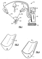
- System 10 has light projector 14, first image capturing device 26, such as a digital camera, at first location 100, second image capturing device 30 at second location 104, and computer 46, having display 48 with keyboard 52.
- System 10 is an optical three-dimensional scanner, such as produced by Capture 3D known as ATOSTM.
- Light projector 14 projects light 16 to form pattern of light 18 on surface 22 of a part, such as turbine blade 24. Pattern of light 18 is scanned across turbine blade 24.
- First reflection 34 is reflected back to first image capturing device 26 while second reflection 38 is reflected back to second imaging capturing device 30.
- first image capturing device 26 may be used alone by first capturing reflection 34 at location 100 and then moving first image capturing device 26 to location 104 and capturing reflection 104 of turbine blade 24 there.
- First reflection 34 forms angle ⁇ with second reflection 38.
- first image capturing device 26 and second image capturing device 30 permit a stereoscopic view of pattern of light on surface 22.
- a surface map of surface 22 can be constructed by computer 46 through known software, such as offered by GEOMAGIC®.
- GEOMAGIC BLADETM may be employed.
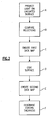
- step A involves projecting light pattern 18 on surface 22 of turbine engine blade 24.
- First image capturing device 26 and second image capturing device 30 are linked to computer 46 and permit the creation of first data map 50 by comparing the first reflection of light pattern 34 with second reflection of light pattern 38 as referenced in step B of Figure 2 .
- First data map 50 is thereby created (see step C).
- First data map 50 may be created following the preparation of surface 22 for coating. In this way, a more accurate representation of dimensions of surface 22 may be created by system 10.
- step D surface 22 of turbine engine blade 24 is then coated in the same manner as all other parts in a particular production run.
- turbine engine blade 24 has surface 22. Following coating, turbine engine blade 24 has surface 22 with coating 62 having thickness T. This thickness may vary across surface 22. Coating 62 may be altered, such as by heat treating or by peening. Following coating, heat treating and peening, surface 22 of turbine engine blade 24 is then placed under light pattern 18. Again, first reflection 34 is read by first image capturing device 26 and second reflection 38 is read by second image capturing device 30. A comparison of these reflections or images permits a creation of second data map 54 representing surface 22 with coating. First data map 50 is then overlayed with second data map 54. A difference between first data map 50 and second data map 54 is then determined, such as by subtracting values of the first data map from values of the second data map. This difference represents thickness of coating T.
- first data map 50 By comparing first data map 50 with second data map 54, thickness of coating 62, T, may be determined without destroying turbine engine blade 24. There is no need to cut parts to determine coating thickness. Furthermore, the process is greatly expedited because a computer 46 has programming that not only creates first data map 50 and second data map 54 but determines a thickness of coating by comparing first data map 50 with second data map 54 automatically. The speed of this process thereby permits all or a larger sampling of parts for inspection for coating thickness.
Landscapes
- Physics & Mathematics (AREA)
- General Physics & Mathematics (AREA)
- Engineering & Computer Science (AREA)
- Computer Vision & Pattern Recognition (AREA)
- Length Measuring Devices By Optical Means (AREA)
Abstract
Description
- This invention relates to a method and system for measuring a thickness of a coating on a part, in particular an optical measuring system.
- Parts for a turbine engine may require a coating to ensure their durability. For this reason, it is important to measure the thickness of the coating on the part. Typically, such an analysis requires cross-sectioning the part and using a microscope to measure the coating's thickness. As a consequence of this method of measurement, the part is destroyed. Inspecting parts in this manner is both expensive and time consuming.
- A need therefore exists for a non-destructive technique and system for measuring the coating thickness.
- The method of measuring a coating thickness involves projecting a pattern of light on a surface. A first reflection of the pattern of light is received at a first imaging capturing device while a second reflection of the pattern of light is received by the same image capturing device at a different location or by another image capturing device. The first reflection is compared to the second reflection. Based on the comparison, a first data map of the surface is created. A coating is then deposited on the surface. A second data map of the surface with the coating is created. The first data map is compared to the second data map to determine the thickness of the coating.
- A system for measuring a coating thickness comprises a system for measuring a coating thickness, comprising a light projector having a light pattern, said light projector for projecting said light pattern on a surface, at least one image capturing device for receiving at least one of a first reflection of said light pattern and a second reflection of said light pattern from a position different than for the first reflection, such that said first reflection forms an angle with said second reflection and a computer in communication with the image capturing device, said computer programmed to compare the first reflection and the second reflection, to create a first data map of the surface and a second data map of the surface with a coating on the surface, and to determine a thickness of the coating by comparing the first data map to the second data map.
- The various features and advantages of this invention will become apparent to those skilled in the art from the following detailed description. The drawings that accompany the detailed description can be briefly described as follows.
-
-
Figure 1 illustrates a view of a system for measuring a coating thickness, including light projector, cameras, light pattern and computer. -
Figure 2 illustrates a flowchart of the technique for measuring a coating thickness employed by the system shown inFigure 1 . -
Figure 3 illustrates a sample turbine blade with an uncoated surface. -
Figure 4 illustrates the sample turbine blade ofFigure 3 with a coated surface. - With reference to
Figure 1 , there is shown a system for measuring a coating thickness.System 10 has light projector 14, firstimage capturing device 26, such as a digital camera, atfirst location 100, secondimage capturing device 30 atsecond location 104, andcomputer 46, havingdisplay 48 withkeyboard 52.System 10 is an optical three-dimensional scanner, such as produced by Capture 3D known as ATOS™. Light projector 14 projects light 16 to form pattern oflight 18 onsurface 22 of a part, such asturbine blade 24. Pattern oflight 18 is scanned acrossturbine blade 24. First reflection 34 is reflected back to firstimage capturing device 26 whilesecond reflection 38 is reflected back to secondimaging capturing device 30. Alternatively to using two image capturing devices, firstimage capturing device 26 may be used alone by first capturing reflection 34 atlocation 100 and then moving firstimage capturing device 26 tolocation 104 and capturingreflection 104 ofturbine blade 24 there. First reflection 34 forms angle α withsecond reflection 38. As a consequence, firstimage capturing device 26 and secondimage capturing device 30 permit a stereoscopic view of pattern of light onsurface 22. Through triangulation as known, a surface map ofsurface 22 can be constructed bycomputer 46 through known software, such as offered by GEOMAGIC®. For a turbine blade, GEOMAGIC BLADE™ may be employed. - With reference to
Figure 2 , the inventive technique for measuring a coating thickness will now be explained. As shown inFigure 2 , the first step, step A, involves projectinglight pattern 18 onsurface 22 ofturbine engine blade 24. Firstimage capturing device 26 and secondimage capturing device 30 are linked tocomputer 46 and permit the creation of first data map 50 by comparing the first reflection of light pattern 34 with second reflection oflight pattern 38 as referenced in step B ofFigure 2 . First data map 50 is thereby created (see step C). First data map 50 may be created following the preparation ofsurface 22 for coating. In this way, a more accurate representation of dimensions ofsurface 22 may be created bysystem 10. With reference to step D,surface 22 ofturbine engine blade 24 is then coated in the same manner as all other parts in a particular production run. As shown inFigure 3 ,turbine engine blade 24 hassurface 22. Following coating,turbine engine blade 24 hassurface 22 withcoating 62 having thickness T. This thickness may vary acrosssurface 22.Coating 62 may be altered, such as by heat treating or by peening. Following coating, heat treating and peening,surface 22 ofturbine engine blade 24 is then placed underlight pattern 18. Again, first reflection 34 is read by firstimage capturing device 26 andsecond reflection 38 is read by secondimage capturing device 30. A comparison of these reflections or images permits a creation of second data map 54 representingsurface 22 with coating. First data map 50 is then overlayed with second data map 54. A difference between first data map 50 and second data map 54 is then determined, such as by subtracting values of the first data map from values of the second data map. This difference represents thickness of coating T. - By comparing first data map 50 with second data map 54, thickness of
coating 62, T, may be determined without destroyingturbine engine blade 24. There is no need to cut parts to determine coating thickness. Furthermore, the process is greatly expedited because acomputer 46 has programming that not only creates first data map 50 and second data map 54 but determines a thickness of coating by comparing first data map 50 with second data map 54 automatically. The speed of this process thereby permits all or a larger sampling of parts for inspection for coating thickness. - The foregoing description shall be interpreted as illustrative and not in any limiting sense. A worker of ordinary skill in the art would recognize that certain modifications would come within the scope of this invention. For that reason, the follow claims should be studied to determine the true scope and content of this invention.
Claims (12)
- A method of measuring a coating thickness (T), comprising the steps of:(a) projecting a pattern of light (18) on a surface (22);(b) receiving a first reflection (34) of the pattern of light (18);(c) receiving a second reflection (3 8) of the pattern of light (18);(d) comparing the first reflection (34) with the second reflection (38);(e) creating a first data map of the surface (22) by comparing the first reflection (34) and the second reflection (38);(f) depositing a coating (62) on the surface (22);(g) repeating steps (a)-(d) on the surface (22) after the step of depositing and thereby creating a second data map of the surface (22) with the coating (62); and(h) comparing the first data map with the second data map to determine a thickness (T) of the coating (62).
- The method of Claim 1 wherein comparing comprises the step of overlaying the first data map and the second data map.
- A method of measuring a coating thickness (T), comprising the steps of:(a) projecting a pattern of light (18) on a surface (22);(b) receiving a first reflection (34) of the pattern of light (18) at a first image capturing device (26);(c) receiving a second reflection (38) of the pattern of light (18) at a second image capturing device (30);(d) comparing the first reflection (34) with the second reflection (38);(e) creating a first data map of the surface (22) by comparing the first reflection (34) and the second reflection (38);(f) depositing a coating (62) on the surface (22);(g) repeating steps (a)-(d) on the surface (22) with the coating (62) and thereby creating a second data map of the surface (22) with the coating (62);(h) comparing the first data map with the second data map by overlaying the first data map and the second data map to determine a thickness (T) of the coating (62).
- The method of any preceding Claim including the step of:(j) determining a difference between the first data map and the second data map.
- The method of Claim 4 wherein the step (j) comprises subtracting values of the first data map from values of the second data map.
- The method of any preceding Claim including the step of:(k) preparing the surface (22) for coating.
- The method of Claim 6 wherein step (k) occurs prior to step (e).
- The method of any preceding Claim including the step of:(l) altering the coating (62) prior to step (g).
- The method of Claim 8 wherein altering the coating (62) comprises heat treating the coating (62).
- The method of Claim 8 wherein altering the coating (62) comprises peening the coating (62).
- The method of any preceding Claim wherein the surface (22) is a turbine engine component surface.
- A system for measuring a coating thickness (T), comprising:a light projector (14) for projecting a light pattern (18) on a surface (22);at least one image capturing device (26,30) for receiving at least one of a first reflection (34) of said light pattern (18) and a second reflection (38) of said light pattern (18) from a position different than for the first reflection (34), such that said first reflection (34) forms an angle with said second reflection (38); anda computer (46) in communication with the image capturing device (26,30), said computer (46) programmed to compare the first reflection (34) and the second reflection (38), to create a first data map of the surface (22) and a second data map of the surface (22) with a coating (62) on the surface (22), and to determine a thickness (T) of the coating (62) by comparing the first data map to the second data map.
Applications Claiming Priority (1)
| Application Number | Priority Date | Filing Date | Title |
|---|---|---|---|
| US12/131,223 US7573586B1 (en) | 2008-06-02 | 2008-06-02 | Method and system for measuring a coating thickness |
Publications (1)
| Publication Number | Publication Date |
|---|---|
| EP2131144A1 true EP2131144A1 (en) | 2009-12-09 |
Family
ID=40934319
Family Applications (1)
| Application Number | Title | Priority Date | Filing Date |
|---|---|---|---|
| EP09250805A Ceased EP2131144A1 (en) | 2008-06-02 | 2009-03-23 | Method and system for measuring a coating thickness |
Country Status (2)
| Country | Link |
|---|---|
| US (1) | US7573586B1 (en) |
| EP (1) | EP2131144A1 (en) |
Cited By (1)
| Publication number | Priority date | Publication date | Assignee | Title |
|---|---|---|---|---|
| EP2674225A3 (en) * | 2012-06-11 | 2017-04-05 | General Electric Company | Spray plume position feeback for robotic motion to optimize coating quality, efficiency, and repeatability |
Families Citing this family (23)
| Publication number | Priority date | Publication date | Assignee | Title |
|---|---|---|---|---|
| TWI353885B (en) * | 2009-06-26 | 2011-12-11 | Primax Electronics Ltd | Thickness detecting mechanism |
| US8609194B2 (en) * | 2010-01-21 | 2013-12-17 | Level 3 Inspection, Llc | Method and apparatus for composition coating for enhancing white light scanning of an object |
| US8899115B2 (en) | 2011-04-20 | 2014-12-02 | United Technologies Corporation | Method and system for locating a laser vibrometer during non-contact scanning |
| US9003670B2 (en) | 2012-03-08 | 2015-04-14 | United Technologies Corporation | System and method for measuring a workpiece relative to a common measurement coordinate system |
| US8942837B2 (en) | 2012-03-12 | 2015-01-27 | United Technologies Corporation | Method for inspecting a manufacturing device |
| US10006756B2 (en) * | 2013-04-02 | 2018-06-26 | United Technologies Corporation | Flexible reference system |
| JP6146276B2 (en) * | 2013-11-27 | 2017-06-14 | 東芝三菱電機産業システム株式会社 | Planar shape measuring device |
| EP3088874B1 (en) | 2013-12-27 | 2023-03-15 | JFE Steel Corporation | Surface defect detection method and surface defect detection device |
| US10137605B2 (en) | 2015-10-01 | 2018-11-27 | United Technologies Corporation | System and method for affixing reference dots with respect to modeling impression materials |
| GB2546957B (en) | 2015-11-13 | 2018-07-04 | Rolls Royce Plc | Surface inspection of an object using multiple images |
| US10121237B1 (en) | 2017-04-17 | 2018-11-06 | Rohr, Inc. | Component inspection method |
| GB2565079A (en) | 2017-07-31 | 2019-02-06 | Erodex Uk Ltd | Inspection system and method for turbine vanes and blades |
| US10276411B2 (en) | 2017-08-18 | 2019-04-30 | Applied Materials, Inc. | High pressure and high temperature anneal chamber |
| US11028480B2 (en) | 2018-03-19 | 2021-06-08 | Applied Materials, Inc. | Methods of protecting metallic components against corrosion using chromium-containing thin films |
| US11015252B2 (en) | 2018-04-27 | 2021-05-25 | Applied Materials, Inc. | Protection of components from corrosion |
| US11009339B2 (en) | 2018-08-23 | 2021-05-18 | Applied Materials, Inc. | Measurement of thickness of thermal barrier coatings using 3D imaging and surface subtraction methods for objects with complex geometries |
| WO2020219332A1 (en) | 2019-04-26 | 2020-10-29 | Applied Materials, Inc. | Methods of protecting aerospace components against corrosion and oxidation |
| US11794382B2 (en) | 2019-05-16 | 2023-10-24 | Applied Materials, Inc. | Methods for depositing anti-coking protective coatings on aerospace components |
| US11697879B2 (en) | 2019-06-14 | 2023-07-11 | Applied Materials, Inc. | Methods for depositing sacrificial coatings on aerospace components |
| US11466364B2 (en) | 2019-09-06 | 2022-10-11 | Applied Materials, Inc. | Methods for forming protective coatings containing crystallized aluminum oxide |
| US11519066B2 (en) | 2020-05-21 | 2022-12-06 | Applied Materials, Inc. | Nitride protective coatings on aerospace components and methods for making the same |
| US11739429B2 (en) | 2020-07-03 | 2023-08-29 | Applied Materials, Inc. | Methods for refurbishing aerospace components |
| NO20231396A1 (en) * | 2023-12-27 | 2025-06-30 | Nexans | Method for manufacturing and inspecting a factory joint during installation |
Citations (5)
| Publication number | Priority date | Publication date | Assignee | Title |
|---|---|---|---|---|
| DE3320160A1 (en) * | 1983-06-03 | 1984-12-06 | Ingenierbüro Schröder GmbH, 5410 Höhr-Grenzhausen | Device for thickness control when coating flat articles, preferably when applying a glazing layer to ceramic plates |
| US6256099B1 (en) * | 1998-11-06 | 2001-07-03 | Frederick Kaufman | Methods and system for measuring three dimensional spatial coordinates and for external camera calibration necessary for that measurement |
| WO2003002936A1 (en) * | 2001-06-29 | 2003-01-09 | Massachusetts Institute Of Technology | Apparatus and methods for optically monitoring thickness |
| US20050018209A1 (en) * | 2003-07-24 | 2005-01-27 | Guylain Lemelin | Optical 3D digitizer with enlarged non-ambiguity zone |
| WO2006116841A1 (en) * | 2005-04-29 | 2006-11-09 | National Research Council Of Canada | Method of on-line thickness measurement of applied coatings |
Family Cites Families (12)
| Publication number | Priority date | Publication date | Assignee | Title |
|---|---|---|---|---|
| FR2082717A5 (en) * | 1970-03-25 | 1971-12-10 | Cellophane Sa | |
| US3979273A (en) | 1975-05-27 | 1976-09-07 | United Technologies Corporation | Method of forming aluminide coatings on nickel-, cobalt-, and iron-base alloys |
| US4132816A (en) | 1976-02-25 | 1979-01-02 | United Technologies Corporation | Gas phase deposition of aluminum using a complex aluminum halide of an alkali metal or an alkaline earth metal as an activator |
| DD151902A1 (en) * | 1980-06-09 | 1981-11-11 | Frank Schumann | METHOD FOR DETERMINING THICKNESS OF ADHESIVE LAYERS ON BOOK BLOCK BACKS |
| US5317901A (en) | 1985-12-10 | 1994-06-07 | United Technologies Corporation | Nondestructive test for coated carbon-carbon composite articles |
| US4978558A (en) | 1988-06-10 | 1990-12-18 | United Technologies Corporation | Method for applying diffusion coating masks |
| US5225246A (en) | 1990-05-14 | 1993-07-06 | United Technologies Corporation | Method for depositing a variable thickness aluminide coating on aircraft turbine blades |
| SE503513C2 (en) | 1994-11-17 | 1996-07-01 | Ericsson Telefon Ab L M | Method and apparatus for determining the thickness and concentricity of a layer applied to a cylindrical body |
| US5757498A (en) | 1996-05-30 | 1998-05-26 | Klein, Ii; Richard J. | Optical spray coating monitoring system and method |
| US6165542A (en) | 1998-12-23 | 2000-12-26 | United Technologies Corporation | Method for fabricating and inspecting coatings |
| DE19928171B4 (en) | 1999-06-19 | 2011-01-05 | Leybold Optics Gmbh | Method for continuously determining the optical layer thickness of coatings |
| US6731277B2 (en) | 2001-03-01 | 2004-05-04 | E. I. Du Pont De Nemours And Company | Process for generating a computer image of a coated three-dimensional object |
-
2008
- 2008-06-02 US US12/131,223 patent/US7573586B1/en active Active
-
2009
- 2009-03-23 EP EP09250805A patent/EP2131144A1/en not_active Ceased
Patent Citations (5)
| Publication number | Priority date | Publication date | Assignee | Title |
|---|---|---|---|---|
| DE3320160A1 (en) * | 1983-06-03 | 1984-12-06 | Ingenierbüro Schröder GmbH, 5410 Höhr-Grenzhausen | Device for thickness control when coating flat articles, preferably when applying a glazing layer to ceramic plates |
| US6256099B1 (en) * | 1998-11-06 | 2001-07-03 | Frederick Kaufman | Methods and system for measuring three dimensional spatial coordinates and for external camera calibration necessary for that measurement |
| WO2003002936A1 (en) * | 2001-06-29 | 2003-01-09 | Massachusetts Institute Of Technology | Apparatus and methods for optically monitoring thickness |
| US20050018209A1 (en) * | 2003-07-24 | 2005-01-27 | Guylain Lemelin | Optical 3D digitizer with enlarged non-ambiguity zone |
| WO2006116841A1 (en) * | 2005-04-29 | 2006-11-09 | National Research Council Of Canada | Method of on-line thickness measurement of applied coatings |
Cited By (2)
| Publication number | Priority date | Publication date | Assignee | Title |
|---|---|---|---|---|
| EP2674225A3 (en) * | 2012-06-11 | 2017-04-05 | General Electric Company | Spray plume position feeback for robotic motion to optimize coating quality, efficiency, and repeatability |
| US11745201B2 (en) | 2012-06-11 | 2023-09-05 | General Electric Company | Spray plume position feedback for robotic motion to optimize coating quality, efficiency, and repeatability |
Also Published As
| Publication number | Publication date |
|---|---|
| US7573586B1 (en) | 2009-08-11 |
Similar Documents
| Publication | Publication Date | Title |
|---|---|---|
| US7573586B1 (en) | Method and system for measuring a coating thickness | |
| US8866891B2 (en) | Method for the non-destructive inspection of a mechanical part | |
| US7327857B2 (en) | Non-contact measurement method and apparatus | |
| EP2257797B1 (en) | System, program product, and related methods for registering three-dimensional models to point data representing the pose of a part | |
| JP6447637B2 (en) | Surface defect detection apparatus, surface defect detection method, and steel material manufacturing method | |
| EP1777491B1 (en) | Method and apparatus for inspecting an object | |
| US20190120770A1 (en) | System and method for imaging a surface defect on an object | |
| CN112033965B (en) | 3D arc surface defect detection method based on differential image analysis | |
| US8205500B2 (en) | Systems and methods for inspecting an object using ultrasound | |
| WO2016208626A1 (en) | Surface flaw detection method, surface flaw detection device, and manufacturing method for steel material | |
| JP5913903B2 (en) | Shape inspection method and apparatus | |
| WO2013061976A1 (en) | Shape inspection method and device | |
| US12553833B2 (en) | Visual inspection apparatus and visual inspection method | |
| US20220044384A1 (en) | Borescope inspection method and device | |
| Drews Jr et al. | Tracking system for underwater inspection using computer vision | |
| Wilken et al. | Localisation of ultrasonic NDT data using hybrid tracking of component and probe | |
| JP2005283267A (en) | Through-hole measuring device and method, and through-hole measuring program | |
| Hong et al. | Optical method for inspecting surface defects inside a small bore | |
| CN113227707B (en) | Three-dimensional shape measuring device, three-dimensional shape measuring method, and storage medium | |
| Bahr et al. | Continuous digitalization of rotationally symmetrical components with a lateral scanning white light interferometer | |
| CN114234811B (en) | Pipeline coarse positioning method and system based on vision and laser ranging | |
| US12620102B2 (en) | Measuring a feature near the edge of an object | |
| Middendorf et al. | Fast measurement of complex geometries using inverse fringe projection | |
| US20240062382A1 (en) | Measuring a feature near the edge of an object | |
| US10475178B1 (en) | System, method and computer program product for inspecting a wafer using a film thickness map generated for the wafer |
Legal Events
| Date | Code | Title | Description |
|---|---|---|---|
| PUAI | Public reference made under article 153(3) epc to a published international application that has entered the european phase |
Free format text: ORIGINAL CODE: 0009012 |
|
| AK | Designated contracting states |
Kind code of ref document: A1 Designated state(s): AT BE BG CH CY CZ DE DK EE ES FI FR GB GR HR HU IE IS IT LI LT LU LV MC MK MT NL NO PL PT RO SE SI SK TR |
|
| AX | Request for extension of the european patent |
Extension state: AL BA RS |
|
| 17P | Request for examination filed |
Effective date: 20091223 |
|
| 17Q | First examination report despatched |
Effective date: 20100126 |
|
| AKX | Designation fees paid |
Designated state(s): DE GB |
|
| STAA | Information on the status of an ep patent application or granted ep patent |
Free format text: STATUS: THE APPLICATION HAS BEEN REFUSED |
|
| 18R | Application refused |
Effective date: 20130118 |