EP2131068B1 - Linear actuator - Google Patents
Linear actuator Download PDFInfo
- Publication number
- EP2131068B1 EP2131068B1 EP09007253A EP09007253A EP2131068B1 EP 2131068 B1 EP2131068 B1 EP 2131068B1 EP 09007253 A EP09007253 A EP 09007253A EP 09007253 A EP09007253 A EP 09007253A EP 2131068 B1 EP2131068 B1 EP 2131068B1
- Authority
- EP
- European Patent Office
- Prior art keywords
- linear actuator
- housing
- half shell
- motor
- spindle
- Prior art date
- Legal status (The legal status is an assumption and is not a legal conclusion. Google has not performed a legal analysis and makes no representation as to the accuracy of the status listed.)
- Not-in-force
Links
- 230000004308 accommodation Effects 0.000 claims abstract description 29
- 230000007246 mechanism Effects 0.000 claims abstract description 20
- 230000033001 locomotion Effects 0.000 claims abstract description 10
- 230000008878 coupling Effects 0.000 claims description 18
- 238000010168 coupling process Methods 0.000 claims description 18
- 238000005859 coupling reaction Methods 0.000 claims description 18
- 239000002184 metal Substances 0.000 claims description 15
- 238000004891 communication Methods 0.000 claims description 3
- 229920003023 plastic Polymers 0.000 claims description 3
- 239000004033 plastic Substances 0.000 claims description 3
- 239000000463 material Substances 0.000 claims description 2
- 230000005540 biological transmission Effects 0.000 abstract description 9
- 238000009434 installation Methods 0.000 description 5
- 238000013461 design Methods 0.000 description 3
- 238000004519 manufacturing process Methods 0.000 description 2
- 230000001960 triggered effect Effects 0.000 description 2
- 230000015572 biosynthetic process Effects 0.000 description 1
- 238000006073 displacement reaction Methods 0.000 description 1
- 239000000428 dust Substances 0.000 description 1
- 238000003780 insertion Methods 0.000 description 1
- 230000037431 insertion Effects 0.000 description 1
- 239000007769 metal material Substances 0.000 description 1
- 238000000034 method Methods 0.000 description 1
- 238000012986 modification Methods 0.000 description 1
- 230000004048 modification Effects 0.000 description 1
- 230000008569 process Effects 0.000 description 1
- 229910000679 solder Inorganic materials 0.000 description 1
- XLYOFNOQVPJJNP-UHFFFAOYSA-N water Substances O XLYOFNOQVPJJNP-UHFFFAOYSA-N 0.000 description 1
Images



Classifications
-
- F—MECHANICAL ENGINEERING; LIGHTING; HEATING; WEAPONS; BLASTING
- F16—ENGINEERING ELEMENTS AND UNITS; GENERAL MEASURES FOR PRODUCING AND MAINTAINING EFFECTIVE FUNCTIONING OF MACHINES OR INSTALLATIONS; THERMAL INSULATION IN GENERAL
- F16H—GEARING
- F16H25/00—Gearings comprising primarily only cams, cam-followers and screw-and-nut mechanisms
- F16H25/18—Gearings comprising primarily only cams, cam-followers and screw-and-nut mechanisms for conveying or interconverting oscillating or reciprocating motions
- F16H25/20—Screw mechanisms
- F16H25/2015—Means specially adapted for stopping actuators in the end position; Position sensing means
-
- F—MECHANICAL ENGINEERING; LIGHTING; HEATING; WEAPONS; BLASTING
- F16—ENGINEERING ELEMENTS AND UNITS; GENERAL MEASURES FOR PRODUCING AND MAINTAINING EFFECTIVE FUNCTIONING OF MACHINES OR INSTALLATIONS; THERMAL INSULATION IN GENERAL
- F16H—GEARING
- F16H25/00—Gearings comprising primarily only cams, cam-followers and screw-and-nut mechanisms
- F16H25/18—Gearings comprising primarily only cams, cam-followers and screw-and-nut mechanisms for conveying or interconverting oscillating or reciprocating motions
- F16H25/20—Screw mechanisms
- F16H2025/2031—Actuator casings
-
- F—MECHANICAL ENGINEERING; LIGHTING; HEATING; WEAPONS; BLASTING
- F16—ENGINEERING ELEMENTS AND UNITS; GENERAL MEASURES FOR PRODUCING AND MAINTAINING EFFECTIVE FUNCTIONING OF MACHINES OR INSTALLATIONS; THERMAL INSULATION IN GENERAL
- F16H—GEARING
- F16H25/00—Gearings comprising primarily only cams, cam-followers and screw-and-nut mechanisms
- F16H25/18—Gearings comprising primarily only cams, cam-followers and screw-and-nut mechanisms for conveying or interconverting oscillating or reciprocating motions
- F16H25/20—Screw mechanisms
- F16H2025/2062—Arrangements for driving the actuator
- F16H2025/2084—Perpendicular arrangement of drive motor to screw axis
-
- F—MECHANICAL ENGINEERING; LIGHTING; HEATING; WEAPONS; BLASTING
- F16—ENGINEERING ELEMENTS AND UNITS; GENERAL MEASURES FOR PRODUCING AND MAINTAINING EFFECTIVE FUNCTIONING OF MACHINES OR INSTALLATIONS; THERMAL INSULATION IN GENERAL
- F16H—GEARING
- F16H25/00—Gearings comprising primarily only cams, cam-followers and screw-and-nut mechanisms
- F16H25/18—Gearings comprising primarily only cams, cam-followers and screw-and-nut mechanisms for conveying or interconverting oscillating or reciprocating motions
- F16H25/20—Screw mechanisms
- F16H2025/2062—Arrangements for driving the actuator
- F16H2025/209—Arrangements for driving the actuator using worm gears
-
- Y—GENERAL TAGGING OF NEW TECHNOLOGICAL DEVELOPMENTS; GENERAL TAGGING OF CROSS-SECTIONAL TECHNOLOGIES SPANNING OVER SEVERAL SECTIONS OF THE IPC; TECHNICAL SUBJECTS COVERED BY FORMER USPC CROSS-REFERENCE ART COLLECTIONS [XRACs] AND DIGESTS
- Y10—TECHNICAL SUBJECTS COVERED BY FORMER USPC
- Y10T—TECHNICAL SUBJECTS COVERED BY FORMER US CLASSIFICATION
- Y10T74/00—Machine element or mechanism
- Y10T74/18—Mechanical movements
- Y10T74/18568—Reciprocating or oscillating to or from alternating rotary
- Y10T74/18576—Reciprocating or oscillating to or from alternating rotary including screw and nut
- Y10T74/18688—Limit stop
Definitions
- the present invention relates to a linear actuator and more particularly, to the structural design of the housing of a linear actuator, which is formed of two half shells, facilitating installation and position adjustment of limit switches.
- linear actuators are known and intensively used in electric hospital beds, treadmills and to facilitate position adjustment.
- limit switches are usually used and respectively mounted in the start end and finish end to control the forward and return strokes of the linear actuator.
- the limit switch is triggered to stop forward movement of the linear actuator.
- the limit switch is triggered to stop backward movement of the linear actuator.
- the linear actuator is controlled to reciprocate with the start end and the finish end.
- FIG. 7 is an exploded view of a linear actuator according to the prior art.
- the linear actuator comprises a housing A, a driving mechanism B, and two limit switches C.
- the housing A comprises a hollow base A1, and an outer tube A2 that extends from one side of the hollow base A1 and defines therein a longitudinal receiving chamber A21.
- the driving mechanism B comprises a motor B1 fastened to one side of the hollow base A1 of the housing A, a worm B11 fixedly connected to the output shaft of the motor B1 and inserted into the inside of the hollow base A1 of the housing A, a spindle B2 rotatable mounted in the longitudinal receiving chamber A21 of the outer tube A2 of the housing A, a worm gear B21 fixedly mounted on one end of the spindle B2 and meshed with the worm B11, a nut B3 threaded onto the spindle B2 and supported inside the longitudinal receiving chamber A21 of the outer tube A2 of the housing A and movable linearly relative to the spindle B2 during rotation of the spindle- B2, and a push rod 4 threaded onto the spindle B2 and extending out of the outer tube A2 of the housing A for connection to an external driven member.
- the nut B3 has a push block B31 protruded from the periphery thereof. Further, a rail C1 is mounted in a longitudinal groove A22 inside the longitudinal receiving chamber A21 of the outer tube A2. Further, two limit switches C are mounted on the rail C1 at selected locations at two opposite sides relative to the push block B31 of the nut B3 at the spindle B2.
- the rail C1 and the limit switches C are mounted in the longitudinal groove A22 inside the longitudinal receiving chamber A21 of the outer tube A2 of the housing A subject to the use of a scale, and then the spindle B2 and the nut B3 are inserted from one end of the longitudinal receiving chamber A21 into the inside of the outer tube A2 of the housing A, and then the transmission shaft B4 is inserted from the other end of the longitudinal receiving chamber A21 into the inside of the outer tube A2 of the housing A and threaded onto the spindle B2.
- the limit switches C may be biased accidentally by the push block B31 of the nut B3.
- Document DE 20 206 018 505 U1 which is considered to represent the closest prior art discloses a linear actuator comprising a housing (14a, 14b), a driving mechanism mounted in said housing, said driving mechanism comprising a motor (11), a spindle (12) coupled to and rotatable by said motor, at least one limit switch (32, 33) controllable by said transmission shaft to switch off said motor, wherein: said housing is formed of a first half shell (14a) and a second half shell (14b), said first half shell and said second half shell being fastened together, defining an accommodation chamber that accommodates said spindle of said driving mechanism, a front opening in communication with a front end of said accommodation chamber for the passing of said push rod to the outside of said housing, and a receiving chamber (see Figure 6 ) at one side of said accommodation chamber for the positioning of said at least one limit switch; said housing comprises a longitudinal seat set between said accommodation chamber and said receiving chamber, a series of transverse grooves (38) located on said longitudinal seat and facing the inside of said accommodation
- a linear actuator in accordance with the present invention is characterised by the features of claims 1 to 10.
- the present invention has been accomplished under the circumstances in view. It is one object of the present invention to provide a linear actuator, which assures positive positioning of the component parts and allows quick detachment of the housing for easy installation and position adjustment of limit switches.
- the linear actuator comprises a housing, a driving mechanism, which is mounted in the housing and comprises a motor, a spindle coupled to and rotatable by the motor and a push rod coupled to the spindle for a linear motion upon rotation of the spindle, and at least one limit switch controllable by the nut of the push rod to switch off the motor.
- the housing is formed of a first half shell and a second half shell.
- the first half shell and the second half shell are fastened together, defining an accommodation chamber that accommodates the spindle and the push rod of the driving mechanism, a front opening in communication with the front end of the accommodation chamber for the passing of the push rod to the outside of the housing, and a receiving chamber at one side of the accommodation chamber for the positioning of the at least one limit switch.
- the housing comprises a tubular front coupling portion formed of a front part of the first half shell and a front part fastened to the tubular front coupling portion to reinforce the strength of the housing.
- a linear actuator in accordance with the present invention comprising a housing 1, a driving mechanism 2 and at least one, for example, two limit switches 3.
- the housing 1 is formed of a first half shell 11 and a second half shell 12, having an accommodation chamber 13 extending along the length thereof, a front opening 131 located on one end of the accommodation chamber 13, a rear compartment 132 located on the other end of the accommodation chamber 13, a bottom receiving chamber 14 located on the bottom side of the accommodation chamber 13, a longitudinal seat 141 set between the accommodation chamber 13 and the bottom receiving chamber 14, a series of transverse grooves 1411 located on the longitudinal seat 141 and facing the inside of the accommodation chamber 13, a tubular front coupling portion 15 extending around the front opening 131, at least one, for example, and two raised portions 151 protruded from the periphery at two opposite sides. Further, a metal retaining ring 16 is capped on the tubular front coupling portion 15, having two retaining holes 161 respectively forced into engagement with the raised portions 151.
- the driving mechanism 2 comprises a motor 21, a worm 211 connected to and rotatable by the motor 21, a push rod 23 having an inner thread 231 axially located on the inside and a nut 232 protruded from the periphery of one end thereof, a spindle 22 threaded into the inner thread 231 of the push rod 23, a worm gear 221 fixedly mounted on one end of the spindle 22 and meshed with the worm 211, and a connector 24 connected to the other end of the push rod 23 remote from the nut 232 for the connection of an external device to be driven by the linear actuator.
- Each limit switch 3 comprises a switch body 31, and a positioning device 32 disposed at one side relative to the switch body 31.
- the switch body 31 has a plurality of electrode pins 311 located on the bottom side thereof.
- the positioning device 32 has a button 321 protruded from the top wall thereof and suspending above the switch body 31 and adapted for triggering the switch body 31, a locating groove 322 located on one lateral side thereof opposite to the switch body 31, at least one, for example, two protruding blocks 323 suspending in one side, namely, the top side of the locating groove 322, and a retaining portion 324 located on the other side, namely, the bottom side of the locating groove 322.
- the first half shell 11 and second half shell 12 of the housing 1 are respectively molded from a plastic material.
- a metal material can be used to make the first half shell 11 and second half shell 12 of the housing 1.
- the worm 211 drives the worm gear 221 to rotate the spindle 22 in the inner thread 231 of the push rod 23, causing the push rod 23 to be moved linearly forwards or backwards.
- the electrode pins 311 of the limit switches 3 are respectively electrically connected to the circuit (not shown) at the start end and finish end of the linear stroke.
- the distance between the two limit switches 3 is determined subject to the designed distance of the linear stroke of the nut 232. Further, the positioning device 32 of each limit switch 3 is fastened to the longitudinal seat 141 in the bottom receiving chamber 14 of the housing 1 by means of forcing the protruding blocks 323 into engagement with the transverse grooves 1411 on the longitudinal seat 141 to have the longitudinal seat 141 is received in the locating groove 322 and retaining portion 324 be abutted against the bottom side of the longitudinal seat 141.
- the formation of the series of transverse grooves 1411 on the longitudinal seat 141 constitutes a rack for engagement with the tooth-like protruding blocks 323 of the positioning device 32 of each limit switch 3.
- the protruding blocks 323 can be made having a rectangular, dovetail-like or arched profile for positive engagement with the series of transverse grooves 1411 on the longitudinal seat 141 and easy removal of the respective limit switch 3 from the longitudinal seat 141.
- FIG. 6 is an exploded view of an alternate form of the linear actuator.
- the housing 1 has a motor chamber 17 perpendicularly connected to the rear compartment 132 for accommodating the motor 21 of the driving mechanism 2. Therefore, the motor 21 is well protected in the motor chamber 17 and will not be forced to bias during delivery of the linear actuator, avoiding improper engagement between the worm gear 221 and the worm 211 or any possible gear tooth damage. Further when the motor 21 in the motor chamber 17 also prevent it from water and dust.
- the positioning device 32 of each limit switch 3 is fastened to the longitudinal seat 141 in the bottom receiving chamber 14 of the housing 1 by means of forcing the protruding blocks 323 into engagement with the transverse grooves 1411 on the longitudinal seat 141, however this arrangement is not a limitation; alternatively the the positioning device 32 of each limit switch 3 can be fastened to the longitudinal seat 141 in the bottom receiving chamber 14 of the housing 1 by a screw joint.
- the invention provides a linear actuator, which has the following advantages and features:
- FIGS. 1 ⁇ 6 A prototype of linear actuator has been constructed with the features of FIGS. 1 ⁇ 6 .
- the linear actuator functions smoothly to provide all of the features disclosed earlier.
- any other linear transmission structures may be used to substitute for the worm and worm gear for transmission of rotary driving force from the motor to the spindle; the metal retaining ring can be made having raised portions and the tubular front coupling portion can be made having retaining holes for engagement with the raised portions of the metal retaining ring. Accordingly, the invention is not to be limited except as by the appended claims.
- Patent Title LINEAR ACTUATOR 1- Housing 2- Driving mechanism 11- First half shell 21- Motor 12- Second half shell 211- Worm 13- Accommodation chamber 22- Spindle 131- Front opening 221- Worm gear 132- Rear compartment 23- Push rod 14- Bottom receiving chamber 231- Inner thread 141- Longitudinal seat 232- Nut 1411- Series of transverse groove 24- Connector 15- Tubular front coupling portion 151- Raised portion 16- Metal retaining ring 161- Retaining hole 17- Motor chamber 3- Limit switch 31- Switch body 311- Electrode pin 32- Positioning device 321- Button 322- Locating groove 323- Protruding block 324- Retaining portion A- Housing A1- Hollow base A2- Outer tube A21- Longitudinal receiving chamber A22- Longitudinal groove B- Driving mechanism B1- Motor B11- Worm B2- Spindle B21- Worm gear B3- Nut B31- Push block B4- Transmission shaft C- Limit switch C1- Rail
Landscapes
- Engineering & Computer Science (AREA)
- General Engineering & Computer Science (AREA)
- Mechanical Engineering (AREA)
- Transmission Devices (AREA)
- Connection Of Motors, Electrical Generators, Mechanical Devices, And The Like (AREA)
Abstract
Description
- The present invention relates to a linear actuator and more particularly, to the structural design of the housing of a linear actuator, which is formed of two half shells, facilitating installation and position adjustment of limit switches.
- Many linear actuators are known and intensively used in electric hospital beds, treadmills and to facilitate position adjustment. During application of a linear actuator, limit switches are usually used and respectively mounted in the start end and finish end to control the forward and return strokes of the linear actuator. When a push block of a nut of the linear actuator touches the limit switch at the finish end during the forward stroke, the limit switch is triggered to stop forward movement of the linear actuator. On the contrary, when the push block of the nut touches the limit switch at the start end during the return stroke, the limit switch is triggered to stop backward movement of the linear actuator. Thus, the linear actuator is controlled to reciprocate with the start end and the finish end.
-
FIG. 7 is an exploded view of a linear actuator according to the prior art. According to this design, the linear actuator comprises a housing A, a driving mechanism B, and two limit switches C. The housing A comprises a hollow base A1, and an outer tube A2 that extends from one side of the hollow base A1 and defines therein a longitudinal receiving chamber A21. The driving mechanism B comprises a motor B1 fastened to one side of the hollow base A1 of the housing A, a worm B11 fixedly connected to the output shaft of the motor B1 and inserted into the inside of the hollow base A1 of the housing A, a spindle B2 rotatable mounted in the longitudinal receiving chamber A21 of the outer tube A2 of the housing A, a worm gear B21 fixedly mounted on one end of the spindle B2 and meshed with the worm B11, a nut B3 threaded onto the spindle B2 and supported inside the longitudinal receiving chamber A21 of the outer tube A2 of the housing A and movable linearly relative to the spindle B2 during rotation of the spindle-B2, and a push rod 4 threaded onto the spindle B2 and extending out of the outer tube A2 of the housing A for connection to an external driven member. The nut B3 has a push block B31 protruded from the periphery thereof. Further, a rail C1 is mounted in a longitudinal groove A22 inside the longitudinal receiving chamber A21 of the outer tube A2. Further, two limit switches C are mounted on the rail C1 at selected locations at two opposite sides relative to the push block B31 of the nut B3 at the spindle B2. - When started the motor B1, the worm B11 is driven to rotate the worm gear B21 and the spindle B2, causing forward or backward movement of the nut B3 and the transmission shaft B4 relative to the spindle B2. When the nut B3 reaches a predetermined position, it will touch one limit switch C, causing the limit switch C to stop the motor B1. In actual practice, this design of linear actuator still has drawbacks as described hereinafter.
- During installation of the linear actuator, the rail C1 and the limit switches C are mounted in the longitudinal groove A22 inside the longitudinal receiving chamber A21 of the outer tube A2 of the housing A subject to the use of a scale, and then the spindle B2 and the nut B3 are inserted from one end of the longitudinal receiving chamber A21 into the inside of the outer tube A2 of the housing A, and then the transmission shaft B4 is inserted from the other end of the longitudinal receiving chamber A21 into the inside of the outer tube A2 of the housing A and threaded onto the spindle B2. During insertion of the spindle B2 and the nut B3 into the longitudinal receiving chamber A21 of the outer tube A2 of the housing A, the limit switches C may be biased accidentally by the push block B31 of the nut B3. When this problem happens, the user needs to re-install the rail C1 and the limit switches C. Further, when wishing to adjust the positions of the limit switches C, the user needs to detach all the parts of the linear actuator, solder the limit switches on the other position and rearrange the wires accordingly.
- Therefore, it is desirable to provide a linear actuator that eliminates the aforesaid drawbacks.
- Document
DE 20 206 018 505 U1 which is considered to represent the closest prior art discloses a linear actuator comprising a housing (14a, 14b), a driving mechanism mounted in said housing, said driving mechanism comprising a motor (11), a spindle (12) coupled to and rotatable by said motor, at least one limit switch (32, 33) controllable by said transmission shaft to switch off said motor, wherein: said housing is formed of a first half shell (14a) and a second half shell (14b), said first half shell and said second half shell being fastened together, defining an accommodation chamber that accommodates said spindle of said driving mechanism, a front opening in communication with a front end of said accommodation chamber for the passing of said push rod to the outside of said housing, and a receiving chamber (seeFigure 6 ) at one side of said accommodation chamber for the positioning of said at least one limit switch; said housing comprises a longitudinal seat set between said accommodation chamber and said receiving chamber, a series of transverse grooves (38) located on said longitudinal seat and facing the inside of said accommodation chamber; each said limit switch comprises a switch body, a button suspending above said switch body for triggering said switch body upon movement of said transmission shaft to a predetermined position, and a positioning device located on one side of said switch body for positioning in said longitudinal seat, said positioning device comprising a locating groove, which receives said longitudinal seat, and at least one protruding block suspending in one side of said locating groove and forced into engagement with said series of transverse grooves. - A linear actuator in accordance with the present invention is characterised by the features of claims 1 to 10.
- The present invention has been accomplished under the circumstances in view. It is one object of the present invention to provide a linear actuator, which assures positive positioning of the component parts and allows quick detachment of the housing for easy installation and position adjustment of limit switches.
- To achieve this and other objects of the present invention, the linear actuator comprises a housing, a driving mechanism, which is mounted in the housing and comprises a motor, a spindle coupled to and rotatable by the motor and a push rod coupled to the spindle for a linear motion upon rotation of the spindle, and at least one limit switch controllable by the nut of the push rod to switch off the motor. The housing is formed of a first half shell and a second half shell. The first half shell and the second half shell are fastened together, defining an accommodation chamber that accommodates the spindle and the push rod of the driving mechanism, a front opening in communication with the front end of the accommodation chamber for the passing of the push rod to the outside of the housing, and a receiving chamber at one side of the accommodation chamber for the positioning of the at least one limit switch.
- The housing comprises a tubular front coupling portion formed of a front part of the first half shell and a front part fastened to the tubular front coupling portion to reinforce the strength of the housing.
-
-
FIG. 1 is an elevational view of a linear actuator in accordance with the present invention. -
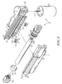
FIG. 2 is an exploded view of the linear actuator in accordance with the present invention. -
FIG. 3 is an elevational view of a limit switch for the linear actuator in accordance with the present invention. -
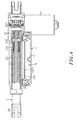
FIG. 4 is a sectional view of the linear actuator in accordance with the present invention. -
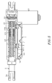
FIG. 5 corresponds toFIG. 4 , showing the position of the front limit switch adjusted. -
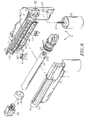
FIG. 6 is an exploded view of an alternate form of the linear actuator in accordance with the present invention. -
FIG. 7 is an exploded view of a linear actuator according to the prior art. - Referring to
FIGS. 1-4 , a linear actuator in accordance with the present invention is shown comprising a housing 1, adriving mechanism 2 and at least one, for example, twolimit switches 3. - The housing 1 is formed of a
first half shell 11 and asecond half shell 12, having anaccommodation chamber 13 extending along the length thereof, afront opening 131 located on one end of theaccommodation chamber 13, arear compartment 132 located on the other end of theaccommodation chamber 13, abottom receiving chamber 14 located on the bottom side of theaccommodation chamber 13, alongitudinal seat 141 set between theaccommodation chamber 13 and thebottom receiving chamber 14, a series oftransverse grooves 1411 located on thelongitudinal seat 141 and facing the inside of theaccommodation chamber 13, a tubularfront coupling portion 15 extending around thefront opening 131, at least one, for example, and two raisedportions 151 protruded from the periphery at two opposite sides. Further, ametal retaining ring 16 is capped on the tubularfront coupling portion 15, having two retainingholes 161 respectively forced into engagement with the raisedportions 151. - The
driving mechanism 2 comprises amotor 21, aworm 211 connected to and rotatable by themotor 21, apush rod 23 having aninner thread 231 axially located on the inside and anut 232 protruded from the periphery of one end thereof, aspindle 22 threaded into theinner thread 231 of thepush rod 23, aworm gear 221 fixedly mounted on one end of thespindle 22 and meshed with theworm 211, and aconnector 24 connected to the other end of thepush rod 23 remote from thenut 232 for the connection of an external device to be driven by the linear actuator. - Each
limit switch 3 comprises aswitch body 31, and apositioning device 32 disposed at one side relative to theswitch body 31. Theswitch body 31 has a plurality ofelectrode pins 311 located on the bottom side thereof. Thepositioning device 32 has abutton 321 protruded from the top wall thereof and suspending above theswitch body 31 and adapted for triggering theswitch body 31, a locatinggroove 322 located on one lateral side thereof opposite to theswitch body 31, at least one, for example, two protrudingblocks 323 suspending in one side, namely, the top side of the locatinggroove 322, and aretaining portion 324 located on the other side, namely, the bottom side of the locatinggroove 322. - During the assembly process of the linear actuator, perpendicularly attach the
motor 21 of thedriving mechanism 2 to the rear end of the housing 1 to insert theworm 211 of themotor 21 into therear compartment 132 of the housing 1 and then fixedly secure themotor 21 to the housing 1, and then thread the spindle-22 into theinner thread 231 of thepush rod 23 and put the push rod-23 with thespindle 22 in theaccommodation chamber 13 of the housing 1 to force theworm gear 221 into engagement with theworm 211 of themotor 21 and to have thepush rod 23 extend out of theaccommodation chamber 13 to the outside of the housing 1 through thefront opening 131, and then fasten thelimit switches 3 to the front and rear sides of thelongitudinal seat 141 in thebottom receiving chamber 14 of the housing 1 to aim thebutton 321 of eachlimit switch 3 at thenut 232 of thepush rod 23, and then fasten thefirst half shell 11 andsecond half shell 12 of the housing 1 together and attach themetal retaining ring 16 to the tubularfront coupling portion 15 of the housing 1 to force the tworetaining hole 161 of themetal retaining ring 16 into engagement with the raisedportions 151 of the tubularfront coupling portion 15 respectively and to reinforce the strength of the housing 1. - According to the present preferred embodiment, the
first half shell 11 andsecond half shell 12 of the housing 1 are respectively molded from a plastic material. Alternatively, a metal material can be used to make thefirst half shell 11 andsecond half shell 12 of the housing 1. - Referring to
FIG. 5 andFIGS. 2~4 again, when started themotor 21 to rotate theworm 211 clockwise or counter-clockwise, theworm 211 drives theworm gear 221 to rotate thespindle 22 in theinner thread 231 of thepush rod 23, causing thepush rod 23 to be moved linearly forwards or backwards. Further, theelectrode pins 311 of thelimit switches 3 are respectively electrically connected to the circuit (not shown) at the start end and finish end of the linear stroke. - When the
nut 232 of thepush rod 23 reaches the finish end during a forward linear motion of thepush rod 23 subject to clockwise rotation of thespindle 22, thenut 232 touches thebutton 321 of thelimit switch 3 at the finish end, causing thelimit switch 3 at the finish end to switch off themotor 21, avoiding disconnection of thepush rod 23 from the front end of thespindle 22. On the contrary, when thenut 232 of thepush rod 23 reaches the start end during a backward linear motion of the push rod-23 subject to counter-clockwise rotation of thespindle 22, the nut-232 touches thebutton 321 of thelimit switch 3 at the start end, causing thelimit switch 3 at the start end to switch off themotor 21, avoiding locking of thespindle 22 and preventing worm gear damage. - The distance between the two
limit switches 3 is determined subject to the designed distance of the linear stroke of thenut 232. Further, thepositioning device 32 of eachlimit switch 3 is fastened to thelongitudinal seat 141 in thebottom receiving chamber 14 of the housing 1 by means of forcing theprotruding blocks 323 into engagement with thetransverse grooves 1411 on thelongitudinal seat 141 to have thelongitudinal seat 141 is received in the locatinggroove 322 and retainingportion 324 be abutted against the bottom side of thelongitudinal seat 141. When wishing to adjust the distance between the twolimit switches 3, remove themetal retaining ring 16 from the tubularfront coupling portion 15 of the housing 1, and then separate thefirst half shell 11 andsecond half shell 12 of the housing 1, and then pull thelimit switch 3 away from thelongitudinal seat 141, and then reinstall thelimit switch 3 in thelongitudinal seat 141 at the selected location. - Further, the formation of the series of
transverse grooves 1411 on thelongitudinal seat 141 constitutes a rack for engagement with the tooth-like protruding blocks 323 of thepositioning device 32 of eachlimit switch 3. Further, theprotruding blocks 323 can be made having a rectangular, dovetail-like or arched profile for positive engagement with the series oftransverse grooves 1411 on thelongitudinal seat 141 and easy removal of therespective limit switch 3 from thelongitudinal seat 141. -
FIG. 6 is an exploded view of an alternate form of the linear actuator. According to this alternate form, the housing 1 has amotor chamber 17 perpendicularly connected to therear compartment 132 for accommodating themotor 21 of thedriving mechanism 2. Therefore, themotor 21 is well protected in themotor chamber 17 and will not be forced to bias during delivery of the linear actuator, avoiding improper engagement between theworm gear 221 and theworm 211 or any possible gear tooth damage. Further when themotor 21 in themotor chamber 17 also prevent it from water and dust. - In the aforesaid embodiment, the
positioning device 32 of eachlimit switch 3 is fastened to thelongitudinal seat 141 in thebottom receiving chamber 14 of the housing 1 by means of forcing theprotruding blocks 323 into engagement with thetransverse grooves 1411 on thelongitudinal seat 141, however this arrangement is not a limitation; alternatively the thepositioning device 32 of eachlimit switch 3 can be fastened to thelongitudinal seat 141 in thebottom receiving chamber 14 of the housing 1 by a screw joint. - In general, the invention provides a linear actuator, which has the following advantages and features:
- 1. The
first half shell 11 and thesecond half shell 12 constitute the housing 1, and themetal retaining ring 16 is fastened to the tubularfront coupling portion 15 of the housing 1 to force the two retainingholes 161 of themetal retaining ring 16 into engagement with the raisedportions 151 of the tubularfront coupling portion 15 and to reinforce the strength of the housing 1. When wishing to adjust the positions of thelimit switches 3, the user can remove themetal retaining ring 16 from the tubularfront coupling portion 15 of the housing 1 and then separate thefirst half shell 11 and thesecond half shell 12 for allowing re-installation of the limit switches 3. Therefore, the invention facilitates adjustment of the positions of thelimit switches 3 and avoids displacement of thelimit switches 3 due to accidental touching by thespindle 22 or pushrod 23 during installation of thedriving mechanism 2. - 2. The
first half shell 11 andsecond half shell 12 of the housing 1 are molded from plastics for the advantages of ease of fabrication and low manufacturing cost. The use of themetal retaining ring 16 assures tight connection of thefirst half shell 11 and thesecond half shell 12 and reinforces the strength of the housing 1, avoiding vibration of thepush rod 23 during operation of thedriving mechanism 2. - A prototype of linear actuator has been constructed with the features of
FIGS. 1~6 . The linear actuator functions smoothly to provide all of the features disclosed earlier. - Although a particular embodiment of the invention has been described in detail for purposes of illustration, various modifications and enhancements may be made without departing from the spirit and scope of the invention. For example, any other linear transmission structures may be used to substitute for the worm and worm gear for transmission of rotary driving force from the motor to the spindle; the metal retaining ring can be made having raised portions and the tubular front coupling portion can be made having retaining holes for engagement with the raised portions of the metal retaining ring. Accordingly, the invention is not to be limited except as by the appended claims.
-
Patent Title : LINEAR ACTUATOR 1- Housing 2- Driving mechanism 11- First half shell 21- Motor 12- Second half shell 211- Worm 13- Accommodation chamber 22- Spindle 131- Front opening 221- Worm gear 132- Rear compartment 23- Push rod 14- Bottom receiving chamber 231- Inner thread 141- Longitudinal seat 232- Nut 1411- Series of transverse groove 24- Connector 15- Tubular front coupling portion 151- Raised portion 16- Metal retaining ring 161- Retaining hole 17- Motor chamber 3- Limit switch 31- Switch body 311- Electrode pin 32- Positioning device 321- Button 322- Locating groove 323- Protruding block 324- Retaining portion A- Housing A1- Hollow base A2- Outer tube A21- Longitudinal receiving chamber A22- Longitudinal groove B- Driving mechanism B1- Motor B11- Worm B2- Spindle B21- Worm gear B3- Nut B31- Push block B4- Transmission shaft C- Limit switch C1- Rail
Claims (10)
- A linear actuator, comprising a housing (1), a driving mechanism mounted in said housing (1), said driving mechanism comprising a motor (21), a spindle (22) coupled to and rotatable by said motor (21), and a push rod (23) coupled to said spindle (22) for a linear motion upon rotation of said spindle (22), and at leat one limit switch (3) controllable by a nut (232) of said push rod (23) to switch off said motor (21), wherein:said housing (1) is formed of a first half shell (11) and a second half shell (12), said first half shell (11) and said second half shell (12) being fastened together, defining an accommodation chamber (13) that accommodates said spindle (22) and said push rod (23) of said driving mechanism, a front opening (131) in communication with a front end of said accommodation chamber (13) for the passing of said push rod (23) to the outside of said housing (1), a tubular front coupling portion (15) formed of a front part of said first half shell (11) and a front part of said second half shell (12) and extending around said front opening, and a metal retaining ring (16) fastened to said tubular front coupling portion (15), and a receiving chamber (14) at one side of said accommodation chamber (13) for the positioning of said at least one limit switch (3); said housing (1) comprises a longitudinal seat (141) set between said accommodation chamber (13) and said receiving chamber (14), a series of transverse grooves (1411) located on said longitudinal seat (141) and facing the inside of said accommodation chamber (13); each said limit switch (3) comprises a switch body (31), a button suspending (321) above said switch body (31) for triggering said switch body (31) by said push rod (23) upon movement of said push rod (23) to a predetermined position, and a positioning device (32) located on one side of said switch body (31) for positioning in said longitudinal seat (141), said positioning device (32) comprising a locating groove (322), which receives said longitudinal seat (141), and at least one protruding block (323) suspending in one side of said locating groove (322) and forced into engagement with said series of transverse grooves (1411).
- The linear actuator as claimed in claim 1, wherein said metal retaining ring (16) is formed by one piece.
- The linear actuator as claimed in claim 1, wherein said tubular front coupling portion (15) comprises at least one male retaining member; said metal retaining ring (16) comprises at least one female retaining member respectively forced into engagement with the male retaining member at said tubular front coupling portion (15).
- The linear actuator as claimed in claim 1, wherein said tubular front coupling portion (15) comprises at least one female retaining member; said metal retaining ring comprises at least one male retaining member respectively forced into engagement with the female retaining member of said tubular front coupling portion.
- The linear actuator as claimed in claim 1, wherein said motor (21) is mounted outside said accommodation chamber (13), comprising an output shaft terminating in a worm (211) and suspending in said accommodation chamber (13); said driving mechanism further comprises a worm gear (221) fixedly mounted on one end of said spindle (22) and meshed with the worm (211) of said motor (21).
- The linear actuator as claimed in claim 5, wherein housing (1) further comprises a rear compartment that accommodates said worm gear (221), and a motor chamber (14) perpendicularly connected to said rear compartment (132) and accommodating said motor (21).
- The linear actuator as claimed in claim 1, wherein said push rod (23) comprises an inner thread meshed (231) with said spindle (22).
- The linear actuator as claimed in claim 1, wherein said limit switch (3) comprises a plurality of electrode pins (311) downwardly extending from said switch body (31).
- The linear actuator as claimed in claim 1, wherein said positioning device (32) of each said limit switch (3) comprises a retaining portion (324) located on an opposite side of said locating groove (322) and abutted against a bottom side of said longitudinal seat (141).
- The linear actuator as claimed in claim 1, wherein said first half shell (11) and said second half shell (12) of said housing (1) are molded from a plastic material.
Applications Claiming Priority (1)
| Application Number | Priority Date | Filing Date | Title |
|---|---|---|---|
| TW097209674U TWM345334U (en) | 2008-06-02 | 2008-06-02 | Actuator shell structure |
Publications (2)
| Publication Number | Publication Date |
|---|---|
| EP2131068A1 EP2131068A1 (en) | 2009-12-09 |
| EP2131068B1 true EP2131068B1 (en) | 2011-08-24 |
Family
ID=41055343
Family Applications (1)
| Application Number | Title | Priority Date | Filing Date |
|---|---|---|---|
| EP09007253A Not-in-force EP2131068B1 (en) | 2008-06-02 | 2009-05-29 | Linear actuator |
Country Status (4)
| Country | Link |
|---|---|
| US (1) | US8109164B2 (en) |
| EP (1) | EP2131068B1 (en) |
| AT (1) | ATE521827T1 (en) |
| TW (1) | TWM345334U (en) |
Families Citing this family (32)
| Publication number | Priority date | Publication date | Assignee | Title |
|---|---|---|---|---|
| JP5414461B2 (en) * | 2009-10-30 | 2014-02-12 | 株式会社ミツバ | Linear actuator |
| CN102667246B (en) * | 2009-11-13 | 2016-03-23 | 利纳克有限公司 | Linear actuators |
| US8448540B2 (en) * | 2009-12-07 | 2013-05-28 | Hiwin Mikrosystem Corp. | Assembling mechanism of a self-locking linear actuator |
| PL2655935T3 (en) * | 2010-12-21 | 2015-07-31 | Linak As | Linear actuator |
| FR2981716B1 (en) * | 2011-10-19 | 2014-08-08 | Inteva Products France Sas | MECHANICAL REDUCER CASING FORMING GUIDE RAIL, OPENING DRIVE SYSTEM |
| DE102011086037A1 (en) | 2011-11-09 | 2013-05-16 | Dewertokin Gmbh | Electromotive linear drive, in particular for adjusting reclining and seating furniture |
| TW201346152A (en) * | 2012-05-10 | 2013-11-16 | Juf Motor Co Ltd | Linear actuator |
| US8794087B2 (en) * | 2012-06-08 | 2014-08-05 | Timotion Technology Co., Ltd. | Gear motor having safety mechanism |
| US9888627B2 (en) | 2012-10-15 | 2018-02-13 | Chervon (Hk) Limited | Lawncare apparatus with a foldable operating arm |
| US11606900B2 (en) | 2012-10-15 | 2023-03-21 | Chervon (Hk) Limited | Gardening tool |
| US9596806B2 (en) | 2013-10-10 | 2017-03-21 | Chervon (Hk) Limited | Control system for controlling the operation of a gardening tool |
| DE102014222895B4 (en) * | 2014-11-10 | 2022-04-28 | Zf Friedrichshafen Ag | Actuator housing for a chassis actuator |
| JP6652833B2 (en) * | 2015-06-03 | 2020-02-26 | 京セラインダストリアルツールズ株式会社 | Power tool connector device |
| US10215264B2 (en) * | 2016-01-11 | 2019-02-26 | The Boeing Company | Linear actuator system with circumferentially and axially adjustable end stop assembly |
| CN205489956U (en) * | 2016-02-02 | 2016-08-17 | 炼马机电(深圳)有限公司 | driver |
| TWM533707U (en) * | 2016-08-01 | 2016-12-11 | Timotion Technology Co Ltd | Micro linear actuator |
| TWM535764U (en) * | 2016-08-12 | 2017-01-21 | Timotion Technology Co Ltd | Modular actuator |
| EP3385113A1 (en) * | 2017-04-03 | 2018-10-10 | Adient US LLC | A drive unit for a vehicle seat |
| BR112019026014A2 (en) * | 2017-06-07 | 2020-06-23 | VIP Cinema LLC | LINEAR ACTUATOR WITH EXTERNAL VARIABLES LIMIT SWITCHES |
| US20190135447A1 (en) * | 2017-11-07 | 2019-05-09 | Hamilton Sundstrand Corporation | Electro-mechanical actuator system for opening and closing of aircraft engine cowl doors |
| US20190257397A1 (en) * | 2018-02-21 | 2019-08-22 | Wilkins Ip, Llc | Coupling assembly and method of coupling |
| US10738866B2 (en) * | 2018-04-19 | 2020-08-11 | Robert Bosch Mexico Sistemas Automotrices S.A. de C.V. | Modular actuator for providing relative motion between two points |
| CN208835918U (en) * | 2018-09-04 | 2019-05-07 | 江苏雷利电机股份有限公司 | Electric machine |
| CN110799773B (en) * | 2018-09-19 | 2022-08-09 | 炼马机电(东莞)有限公司 | Driver |
| USD852248S1 (en) * | 2018-12-19 | 2019-06-25 | Timotion Technology Co., Ltd. | Linear actuator |
| EP3851622B1 (en) * | 2020-01-17 | 2022-03-23 | FLAP Competence Center kft | Drive device for moving a displaceable part of a piece of furniture and a fitting arrangement and furniture comprising such a drive device |
| US11638397B2 (en) | 2020-02-10 | 2023-05-02 | Techtronic Cordless Gp | Control assembly coupled to handle of an implement |
| DE102020118449A1 (en) * | 2020-07-13 | 2022-01-13 | Ewellix AB | Linear Actuator, Housing, Actuation System, and Assembly Method |
| CN214617727U (en) * | 2021-01-11 | 2021-11-05 | 捷世达企业股份有限公司 | Linear actuator |
| EP4063690A1 (en) * | 2021-03-23 | 2022-09-28 | Regner Engineering, S.L.U. | Electric linear actuator with a variable stroke |
| US12022949B2 (en) | 2022-10-13 | 2024-07-02 | Hidden Lake 822, Llc | Drive motor-linear actuator system for powered lift or powered reclining chairs |
| EP4582718A1 (en) * | 2024-01-08 | 2025-07-09 | Phoenix Mecano Solutions AG | Linear movement device |
Family Cites Families (9)
| Publication number | Priority date | Publication date | Assignee | Title |
|---|---|---|---|---|
| US3529104A (en) * | 1968-04-19 | 1970-09-15 | Plessey Airborne Corp | Limit switch operating mechanism for actuators |
| DE29604293U1 (en) * | 1996-03-08 | 1997-07-03 | Dewert Antriebs- und Systemtechnik GmbH & Co KG, 32278 Kirchlengern | Electromotive furniture drive |
| IT240544Y1 (en) * | 1996-03-25 | 2001-04-02 | Ciar Srl | LINEAR ACTUATOR WITH END OF STROKE MICROSWITCHES WITH HIGH REGULATION SIMPLICITY. |
| DE29811566U1 (en) * | 1998-06-29 | 1998-08-20 | Dewert Antriebs- und Systemtechnik GmbH & Co KG, 32278 Kirchlengern | Electromotive furniture drive |
| US6259175B1 (en) * | 1999-11-18 | 2001-07-10 | Dana Corporation | Linear actuator |
| DE20005065U1 (en) * | 2000-03-20 | 2000-05-25 | Dewert Antriebs- und Systemtechnik GmbH & Co KG, 32278 Kirchlengern | Double worm gear drive |
| HUE028346T2 (en) * | 2005-07-13 | 2016-12-28 | Linak As | Actuator with means for determining the position of an activation element |
| US7611128B2 (en) * | 2006-08-30 | 2009-11-03 | Moteck Electric Corp. | Lifter |
| DE202006018505U1 (en) * | 2006-12-05 | 2008-04-17 | Dewert Antriebs- Und Systemtechnik Gmbh | Electromotive linear drive |
-
2008
- 2008-06-02 TW TW097209674U patent/TWM345334U/en not_active IP Right Cessation
-
2009
- 2009-05-26 US US12/471,504 patent/US8109164B2/en not_active Expired - Fee Related
- 2009-05-29 AT AT09007253T patent/ATE521827T1/en not_active IP Right Cessation
- 2009-05-29 EP EP09007253A patent/EP2131068B1/en not_active Not-in-force
Also Published As
| Publication number | Publication date |
|---|---|
| TWM345334U (en) | 2008-11-21 |
| EP2131068A1 (en) | 2009-12-09 |
| ATE521827T1 (en) | 2011-09-15 |
| US8109164B2 (en) | 2012-02-07 |
| US20090293655A1 (en) | 2009-12-03 |
Similar Documents
| Publication | Publication Date | Title |
|---|---|---|
| EP2131068A1 (en) | Linear actuator | |
| US9989133B2 (en) | Modular actuator | |
| US7066041B2 (en) | Linear actuator | |
| JP6091465B2 (en) | Linear actuator | |
| US8201468B2 (en) | Electromotive furniture double drive and switch arrangement | |
| US8202235B2 (en) | Single-motor massager | |
| US20180031091A1 (en) | Miniature linear actuator | |
| US20100276564A1 (en) | Household appliance having a height-adjusting device for an appliance pedestal | |
| CN110575587B (en) | Automatic injection device | |
| CN110799773B (en) | Driver | |
| EP0647799A2 (en) | Linear actuator | |
| JP5535602B2 (en) | Linear actuator | |
| US20060076738A1 (en) | Quick change coupler | |
| KR100818615B1 (en) | Limit switch device | |
| CN108125758B (en) | Bed board separable four-direction side-turning electric control sickbed | |
| EP3646446B1 (en) | Linear actuator | |
| CN113216751A (en) | Connecting mechanism for unlocking and locking robot and unlocking and locking robot | |
| CN220526787U (en) | Push button switch | |
| EP1205687A1 (en) | Adjustment drive | |
| CN218868038U (en) | Electric push rod with adjustable stroke and installation | |
| CN217501337U (en) | Electronic lock device | |
| WO2020211079A1 (en) | Drive device | |
| CN108210207B (en) | Transmission device for detachable four-direction side-turning electric control sickbed | |
| WO2004113126A1 (en) | Vehicle mirror with powered extension incorporating slip clutch | |
| CN222888757U (en) | Adjustable headrest for seat and seat |
Legal Events
| Date | Code | Title | Description |
|---|---|---|---|
| PUAI | Public reference made under article 153(3) epc to a published international application that has entered the european phase |
Free format text: ORIGINAL CODE: 0009012 |
|
| AK | Designated contracting states |
Kind code of ref document: A1 Designated state(s): AT BE BG CH CY CZ DE DK EE ES FI FR GB GR HR HU IE IS IT LI LT LU LV MC MK MT NL NO PL PT RO SE SI SK TR |
|
| 17P | Request for examination filed |
Effective date: 20100519 |
|
| GRAP | Despatch of communication of intention to grant a patent |
Free format text: ORIGINAL CODE: EPIDOSNIGR1 |
|
| GRAS | Grant fee paid |
Free format text: ORIGINAL CODE: EPIDOSNIGR3 |
|
| GRAA | (expected) grant |
Free format text: ORIGINAL CODE: 0009210 |
|
| AK | Designated contracting states |
Kind code of ref document: B1 Designated state(s): AT BE BG CH CY CZ DE DK EE ES FI FR GB GR HR HU IE IS IT LI LT LU LV MC MK MT NL NO PL PT RO SE SI SK TR |
|
| REG | Reference to a national code |
Ref country code: GB Ref legal event code: FG4D |
|
| REG | Reference to a national code |
Ref country code: CH Ref legal event code: EP |
|
| REG | Reference to a national code |
Ref country code: IE Ref legal event code: FG4D |
|
| REG | Reference to a national code |
Ref country code: DE Ref legal event code: R096 Ref document number: 602009002221 Country of ref document: DE Effective date: 20111124 |
|
| REG | Reference to a national code |
Ref country code: NL Ref legal event code: VDEP Effective date: 20110824 |
|
| LTIE | Lt: invalidation of european patent or patent extension |
Effective date: 20110824 |
|
| PG25 | Lapsed in a contracting state [announced via postgrant information from national office to epo] |
Ref country code: NO Free format text: LAPSE BECAUSE OF FAILURE TO SUBMIT A TRANSLATION OF THE DESCRIPTION OR TO PAY THE FEE WITHIN THE PRESCRIBED TIME-LIMIT Effective date: 20111124 Ref country code: IS Free format text: LAPSE BECAUSE OF FAILURE TO SUBMIT A TRANSLATION OF THE DESCRIPTION OR TO PAY THE FEE WITHIN THE PRESCRIBED TIME-LIMIT Effective date: 20111224 Ref country code: LT Free format text: LAPSE BECAUSE OF FAILURE TO SUBMIT A TRANSLATION OF THE DESCRIPTION OR TO PAY THE FEE WITHIN THE PRESCRIBED TIME-LIMIT Effective date: 20110824 Ref country code: SE Free format text: LAPSE BECAUSE OF FAILURE TO SUBMIT A TRANSLATION OF THE DESCRIPTION OR TO PAY THE FEE WITHIN THE PRESCRIBED TIME-LIMIT Effective date: 20110824 Ref country code: FI Free format text: LAPSE BECAUSE OF FAILURE TO SUBMIT A TRANSLATION OF THE DESCRIPTION OR TO PAY THE FEE WITHIN THE PRESCRIBED TIME-LIMIT Effective date: 20110824 Ref country code: NL Free format text: LAPSE BECAUSE OF FAILURE TO SUBMIT A TRANSLATION OF THE DESCRIPTION OR TO PAY THE FEE WITHIN THE PRESCRIBED TIME-LIMIT Effective date: 20110824 Ref country code: HR Free format text: LAPSE BECAUSE OF FAILURE TO SUBMIT A TRANSLATION OF THE DESCRIPTION OR TO PAY THE FEE WITHIN THE PRESCRIBED TIME-LIMIT Effective date: 20110824 Ref country code: PT Free format text: LAPSE BECAUSE OF FAILURE TO SUBMIT A TRANSLATION OF THE DESCRIPTION OR TO PAY THE FEE WITHIN THE PRESCRIBED TIME-LIMIT Effective date: 20111226 |
|
| REG | Reference to a national code |
Ref country code: AT Ref legal event code: MK05 Ref document number: 521827 Country of ref document: AT Kind code of ref document: T Effective date: 20110824 |
|
| PG25 | Lapsed in a contracting state [announced via postgrant information from national office to epo] |
Ref country code: CY Free format text: LAPSE BECAUSE OF FAILURE TO SUBMIT A TRANSLATION OF THE DESCRIPTION OR TO PAY THE FEE WITHIN THE PRESCRIBED TIME-LIMIT Effective date: 20110824 Ref country code: LV Free format text: LAPSE BECAUSE OF FAILURE TO SUBMIT A TRANSLATION OF THE DESCRIPTION OR TO PAY THE FEE WITHIN THE PRESCRIBED TIME-LIMIT Effective date: 20110824 Ref country code: SI Free format text: LAPSE BECAUSE OF FAILURE TO SUBMIT A TRANSLATION OF THE DESCRIPTION OR TO PAY THE FEE WITHIN THE PRESCRIBED TIME-LIMIT Effective date: 20110824 Ref country code: PL Free format text: LAPSE BECAUSE OF FAILURE TO SUBMIT A TRANSLATION OF THE DESCRIPTION OR TO PAY THE FEE WITHIN THE PRESCRIBED TIME-LIMIT Effective date: 20110824 Ref country code: AT Free format text: LAPSE BECAUSE OF FAILURE TO SUBMIT A TRANSLATION OF THE DESCRIPTION OR TO PAY THE FEE WITHIN THE PRESCRIBED TIME-LIMIT Effective date: 20110824 Ref country code: GR Free format text: LAPSE BECAUSE OF FAILURE TO SUBMIT A TRANSLATION OF THE DESCRIPTION OR TO PAY THE FEE WITHIN THE PRESCRIBED TIME-LIMIT Effective date: 20111125 |
|
| PG25 | Lapsed in a contracting state [announced via postgrant information from national office to epo] |
Ref country code: BE Free format text: LAPSE BECAUSE OF FAILURE TO SUBMIT A TRANSLATION OF THE DESCRIPTION OR TO PAY THE FEE WITHIN THE PRESCRIBED TIME-LIMIT Effective date: 20110824 |
|
| PG25 | Lapsed in a contracting state [announced via postgrant information from national office to epo] |
Ref country code: SK Free format text: LAPSE BECAUSE OF FAILURE TO SUBMIT A TRANSLATION OF THE DESCRIPTION OR TO PAY THE FEE WITHIN THE PRESCRIBED TIME-LIMIT Effective date: 20110824 Ref country code: CZ Free format text: LAPSE BECAUSE OF FAILURE TO SUBMIT A TRANSLATION OF THE DESCRIPTION OR TO PAY THE FEE WITHIN THE PRESCRIBED TIME-LIMIT Effective date: 20110824 |
|
| PG25 | Lapsed in a contracting state [announced via postgrant information from national office to epo] |
Ref country code: IT Free format text: LAPSE BECAUSE OF FAILURE TO SUBMIT A TRANSLATION OF THE DESCRIPTION OR TO PAY THE FEE WITHIN THE PRESCRIBED TIME-LIMIT Effective date: 20110824 Ref country code: EE Free format text: LAPSE BECAUSE OF FAILURE TO SUBMIT A TRANSLATION OF THE DESCRIPTION OR TO PAY THE FEE WITHIN THE PRESCRIBED TIME-LIMIT Effective date: 20110824 Ref country code: RO Free format text: LAPSE BECAUSE OF FAILURE TO SUBMIT A TRANSLATION OF THE DESCRIPTION OR TO PAY THE FEE WITHIN THE PRESCRIBED TIME-LIMIT Effective date: 20110824 |
|
| PG25 | Lapsed in a contracting state [announced via postgrant information from national office to epo] |
Ref country code: DK Free format text: LAPSE BECAUSE OF FAILURE TO SUBMIT A TRANSLATION OF THE DESCRIPTION OR TO PAY THE FEE WITHIN THE PRESCRIBED TIME-LIMIT Effective date: 20110824 |
|
| PLBE | No opposition filed within time limit |
Free format text: ORIGINAL CODE: 0009261 |
|
| STAA | Information on the status of an ep patent application or granted ep patent |
Free format text: STATUS: NO OPPOSITION FILED WITHIN TIME LIMIT |
|
| 26N | No opposition filed |
Effective date: 20120525 |
|
| REG | Reference to a national code |
Ref country code: DE Ref legal event code: R097 Ref document number: 602009002221 Country of ref document: DE Effective date: 20120525 |
|
| PG25 | Lapsed in a contracting state [announced via postgrant information from national office to epo] |
Ref country code: MC Free format text: LAPSE BECAUSE OF NON-PAYMENT OF DUE FEES Effective date: 20120531 |
|
| REG | Reference to a national code |
Ref country code: IE Ref legal event code: MM4A |
|
| PG25 | Lapsed in a contracting state [announced via postgrant information from national office to epo] |
Ref country code: MK Free format text: LAPSE BECAUSE OF FAILURE TO SUBMIT A TRANSLATION OF THE DESCRIPTION OR TO PAY THE FEE WITHIN THE PRESCRIBED TIME-LIMIT Effective date: 20110824 |
|
| PG25 | Lapsed in a contracting state [announced via postgrant information from national office to epo] |
Ref country code: ES Free format text: LAPSE BECAUSE OF FAILURE TO SUBMIT A TRANSLATION OF THE DESCRIPTION OR TO PAY THE FEE WITHIN THE PRESCRIBED TIME-LIMIT Effective date: 20111205 Ref country code: IE Free format text: LAPSE BECAUSE OF NON-PAYMENT OF DUE FEES Effective date: 20120529 |
|
| PG25 | Lapsed in a contracting state [announced via postgrant information from national office to epo] |
Ref country code: BG Free format text: LAPSE BECAUSE OF FAILURE TO SUBMIT A TRANSLATION OF THE DESCRIPTION OR TO PAY THE FEE WITHIN THE PRESCRIBED TIME-LIMIT Effective date: 20111124 |
|
| PG25 | Lapsed in a contracting state [announced via postgrant information from national office to epo] |
Ref country code: MT Free format text: LAPSE BECAUSE OF FAILURE TO SUBMIT A TRANSLATION OF THE DESCRIPTION OR TO PAY THE FEE WITHIN THE PRESCRIBED TIME-LIMIT Effective date: 20110824 |
|
| REG | Reference to a national code |
Ref country code: CH Ref legal event code: PL |
|
| GBPC | Gb: european patent ceased through non-payment of renewal fee |
Effective date: 20130529 |
|
| PG25 | Lapsed in a contracting state [announced via postgrant information from national office to epo] |
Ref country code: CH Free format text: LAPSE BECAUSE OF NON-PAYMENT OF DUE FEES Effective date: 20130531 Ref country code: LI Free format text: LAPSE BECAUSE OF NON-PAYMENT OF DUE FEES Effective date: 20130531 |
|
| PG25 | Lapsed in a contracting state [announced via postgrant information from national office to epo] |
Ref country code: GB Free format text: LAPSE BECAUSE OF NON-PAYMENT OF DUE FEES Effective date: 20130529 Ref country code: TR Free format text: LAPSE BECAUSE OF FAILURE TO SUBMIT A TRANSLATION OF THE DESCRIPTION OR TO PAY THE FEE WITHIN THE PRESCRIBED TIME-LIMIT Effective date: 20110824 |
|
| PG25 | Lapsed in a contracting state [announced via postgrant information from national office to epo] |
Ref country code: LU Free format text: LAPSE BECAUSE OF NON-PAYMENT OF DUE FEES Effective date: 20120529 |
|
| PG25 | Lapsed in a contracting state [announced via postgrant information from national office to epo] |
Ref country code: HU Free format text: LAPSE BECAUSE OF FAILURE TO SUBMIT A TRANSLATION OF THE DESCRIPTION OR TO PAY THE FEE WITHIN THE PRESCRIBED TIME-LIMIT Effective date: 20090529 |
|
| REG | Reference to a national code |
Ref country code: FR Ref legal event code: PLFP Year of fee payment: 7 |
|
| PGFP | Annual fee paid to national office [announced via postgrant information from national office to epo] |
Ref country code: FR Payment date: 20150519 Year of fee payment: 7 |
|
| PGFP | Annual fee paid to national office [announced via postgrant information from national office to epo] |
Ref country code: DE Payment date: 20150724 Year of fee payment: 7 |
|
| REG | Reference to a national code |
Ref country code: DE Ref legal event code: R082 Ref document number: 602009002221 Country of ref document: DE |
|
| REG | Reference to a national code |
Ref country code: DE Ref legal event code: R119 Ref document number: 602009002221 Country of ref document: DE |
|
| REG | Reference to a national code |
Ref country code: FR Ref legal event code: ST Effective date: 20170131 |
|
| PG25 | Lapsed in a contracting state [announced via postgrant information from national office to epo] |
Ref country code: FR Free format text: LAPSE BECAUSE OF NON-PAYMENT OF DUE FEES Effective date: 20160531 Ref country code: DE Free format text: LAPSE BECAUSE OF NON-PAYMENT OF DUE FEES Effective date: 20161201 |