EP2128777A2 - Method for designing part made from composite material and having a curved surface - Google Patents
Method for designing part made from composite material and having a curved surface Download PDFInfo
- Publication number
- EP2128777A2 EP2128777A2 EP07730481A EP07730481A EP2128777A2 EP 2128777 A2 EP2128777 A2 EP 2128777A2 EP 07730481 A EP07730481 A EP 07730481A EP 07730481 A EP07730481 A EP 07730481A EP 2128777 A2 EP2128777 A2 EP 2128777A2
- Authority
- EP
- European Patent Office
- Prior art keywords
- curved surface
- developed
- fabric model
- references
- composite material
- Prior art date
- Legal status (The legal status is an assumption and is not a legal conclusion. Google has not performed a legal analysis and makes no representation as to the accuracy of the status listed.)
- Withdrawn
Links
Images

Classifications
-
- G—PHYSICS
- G06—COMPUTING OR CALCULATING; COUNTING
- G06F—ELECTRIC DIGITAL DATA PROCESSING
- G06F30/00—Computer-aided design [CAD]
- G06F30/10—Geometric CAD
-
- G—PHYSICS
- G06—COMPUTING OR CALCULATING; COUNTING
- G06F—ELECTRIC DIGITAL DATA PROCESSING
- G06F30/00—Computer-aided design [CAD]
-
- G—PHYSICS
- G06—COMPUTING OR CALCULATING; COUNTING
- G06F—ELECTRIC DIGITAL DATA PROCESSING
- G06F2113/00—Details relating to the application field
- G06F2113/24—Sheet material
-
- G—PHYSICS
- G06—COMPUTING OR CALCULATING; COUNTING
- G06F—ELECTRIC DIGITAL DATA PROCESSING
- G06F2113/00—Details relating to the application field
- G06F2113/26—Composites
-
- G—PHYSICS
- G06—COMPUTING OR CALCULATING; COUNTING
- G06F—ELECTRIC DIGITAL DATA PROCESSING
- G06F2119/00—Details relating to the type or aim of the analysis or the optimisation
- G06F2119/18—Manufacturability analysis or optimisation for manufacturability
-
- Y—GENERAL TAGGING OF NEW TECHNOLOGICAL DEVELOPMENTS; GENERAL TAGGING OF CROSS-SECTIONAL TECHNOLOGIES SPANNING OVER SEVERAL SECTIONS OF THE IPC; TECHNICAL SUBJECTS COVERED BY FORMER USPC CROSS-REFERENCE ART COLLECTIONS [XRACs] AND DIGESTS
- Y02—TECHNOLOGIES OR APPLICATIONS FOR MITIGATION OR ADAPTATION AGAINST CLIMATE CHANGE
- Y02P—CLIMATE CHANGE MITIGATION TECHNOLOGIES IN THE PRODUCTION OR PROCESSING OF GOODS
- Y02P90/00—Enabling technologies with a potential contribution to greenhouse gas [GHG] emissions mitigation
- Y02P90/02—Total factory control, e.g. smart factories, flexible manufacturing systems [FMS] or integrated manufacturing systems [IMS]
Definitions
- the present invention relates to a method for designing a composite material part with a curved surface and more particularly, for designing a composite material part with a curved surface such as a tubular part, to which stiffening elements such as transverse frames and longitudinal stringers will be joined.
- wing skins, coating panels and fuselage sections are parts which can be manufactured using composite materials.
- These parts are generally made with laminates of composite material fabrics with carbon fibers arranged in different orientations.
- the process can be more or less simplified depending on the CAD system used, when the designers are faced with complex support surface where the geometric computation is slow, the times for generating the fabric models of the parts can be excessively long. The designer may lose his or her concentration, making more mistakes due to the downtimes that the CAD system generates in the geometric operation computation. This is added to the fact that in some cases such as in tubular surfaces, the fabric model can be so complex that after hours of work, there is no clear vision of the work done due to the confusion caused by the geometry intersection in three-dimensional space.
- the present invention intends to solve this problem.
- An object of the present invention is to reduce the time currently used in designing fabric models of composite material parts with a curved surface.
- Another object of the present invention is to provide a computer tool which can be used together with a CAD system to implement the mentioned model.
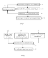
- the design of a composite material part is a complex process which, as shown in Figure 1 , comprises a first phase 11, in which the basic data of the laminate are specified taking into account the loads that it must support, a second phase 13 in which the fabric model is designed, a third phase 15 in which the producibility of the design is analyzed, a fourth phase 17 in which the design is possibly modified, in which case, the previous corresponding step is repeated to carry out the corresponding adjustments, and a final phase 19 in which the information required to manufacture the part is obtained.
- the present invention relates to the phase 13 for designing the fabric model of a curved surface part using a CAD system.
- this phase is developed following the scheme of Figure 2 .
- the inputs of this phase are:
- the 3D references necessary for generating the fabric model are obtained in a first step 27, which references basically consist of the intersections of the structural entities with the support surface and in curves parallel thereto.
- the design of the fabric model in 3D i.e. the definition of the contours of the different fabrics forming the laminate of the part, is carried out in a second step 29.
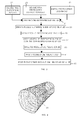
- the phase for designing the fabric model is developed by following the scheme of Figure 3 which will be explained in detail below in relation to an embodiment of the invention applied to a tubular curved part stiffened with transverse frames and longitudinal stringers.
- the starting data are the same as those used in the known art: the geometry of the support surface 21, the geometry of the structural entities 23 (i.e. the frames and the stringers) and the specifications of the laminate 25.
- the 3D references are generated by means of the following steps:
- a second step 33 the curved surface is developed in a plane. i.e. in 2D, by means of the following steps:
- each 3D reference is associated with its corresponding 2D reference by means of the following steps:
- a fifth step 39 the contours 75 of the fabrics are created in 2D (see Figure 11 ).
- the fabric model is passed into the 3D environment (see Figure 12 ).
- the fabric model can be modified both in the 2D environment and in the 3D environment.
- the basic principle of the method according to the present invention consists of preparing the same starting information in the 3D and in the 2d environment for the purpose of generating references 51, 71 in 3D and in 2D respectively, and of being able to change from one environment to the other according to the needs of the designer.
- a series of computer tools is used together with a conventional CAD system or a system included therein, which computer tools carry out the mentioned operations and particularly those relating to:
- the present invention is applicable to both “developable” curved surface and to “non-developable” curved surfaces in the strictly mathematical sense of these terms. In this sense and as will be understood by persons skilled in the art, one of the known methods of "flattening" "non-developable” surfaces can be used in the case of "non-developable” surfaces in the generation of the 2D environment.
Landscapes
- Engineering & Computer Science (AREA)
- Physics & Mathematics (AREA)
- Theoretical Computer Science (AREA)
- General Physics & Mathematics (AREA)
- Geometry (AREA)
- Evolutionary Computation (AREA)
- General Engineering & Computer Science (AREA)
- Computer Hardware Design (AREA)
- Computational Mathematics (AREA)
- Mathematical Analysis (AREA)
- Mathematical Optimization (AREA)
- Pure & Applied Mathematics (AREA)
- Processing Or Creating Images (AREA)
- Moulds For Moulding Plastics Or The Like (AREA)
Abstract
Description
- The present invention relates to a method for designing a composite material part with a curved surface and more particularly, for designing a composite material part with a curved surface such as a tubular part, to which stiffening elements such as transverse frames and longitudinal stringers will be joined.
- In several engineering fields there is a strong tendency to increase the amount of parts made of composite materials. For example, in the aeronautic field, wing skins, coating panels and fuselage sections are parts which can be manufactured using composite materials.
- These parts are generally made with laminates of composite material fabrics with carbon fibers arranged in different orientations.
- These parts are designed by means of a complex process comprising calculation steps, steps for designing the fabric model and for analyzing their producibility, with feedback loops when modifications are introduced in any of these steps.
- Engineers who are specialists in calculations use calculation programs to calculate the performance of the part under given loads, and design engineers use CAD systems to generate the fabric model, i.e. define the location and contour of the fabrics forming the laminate, from the laminate specifications provided by the results of the calculation.
- Even with CAD systems functionalities, the process for generating the mentioned fabric models in CAD systems is a tedious process involving a large amount of repetitive manual work, with the subsequent risk of failures, especially in the case of curved parts in which the definition of the contour of the fabrics, ensuring that certain requirements are complied with, is very complex and laborious.
- Although the process can be more or less simplified depending on the CAD system used, when the designers are faced with complex support surface where the geometric computation is slow, the times for generating the fabric models of the parts can be excessively long. The designer may lose his or her concentration, making more mistakes due to the downtimes that the CAD system generates in the geometric operation computation. This is added to the fact that in some cases such as in tubular surfaces, the fabric model can be so complex that after hours of work, there is no clear vision of the work done due to the confusion caused by the geometry intersection in three-dimensional space.
- The present invention intends to solve this problem.
- An object of the present invention is to reduce the time currently used in designing fabric models of composite material parts with a curved surface.
- The previous and other objects are achieved by providing a method for carrying out the phase for designing the fabric model from a process for designing a composite material part with a curved surface to which a plurality of stiffening parts oriented in planes that are considerably perpendicular to said curved surface will be joined, by means of the following steps:
- Generating a planar surface developed in 2D of the surface of the curved part as well as the same geometric references in 2D as the references of the curved surface in 3D.
- Associating the surface developed in 2D and the curved surface in 3D as well as their geometric references, such that any action in one of them is reflected in the other.
- Initially computing the fabric model in the surface developed in 2D.
- Carrying out any subsequent modification of the fabric model either in the surface developed in 2D or in the curved surface in 3D.
- Another object of the present invention is to provide a computer tool which can be used together with a CAD system to implement the mentioned model.
- This object is achieved by means of a tool which, among other functionalities, allows carrying out the following actions:
- Developing in 2D the same geometric elements used in a CAD system for designing a fabric model.
- Associating the 2D and 3D environments by means of a Composite Surface with a 2D domain and a 3D domain.
- Updating the CAD system with the information resulting from the work in any of said domains.
- Other features and advantages of the present invention will be apparent from the following detailed description of the embodiments illustrating its object together with the attached figures.
-
-
Figure 1 shows a block diagram illustrating the method for designing a composite material part. -
Figure 2 shows a block diagram illustrating the method used in the prior art for generating the fabric model. -
Figure 3 shows a block diagram illustrating the method for generating the fabric model according to the present invention. -
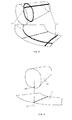
Figure 4 shows the intersections of a tubular curved surface with an assembly of structural entities. -
Figure 5 shows the step of the method for generating the fabric model according to the present invention in which the 3D references are generated. -
Figure 6 shows the step of the method for generating the fabric model according to the present invention in which the curved support surface is developed in 2D, one of the elements of the 2D environment being generated. -
Figure 7 shows the development in 2D of the 3D references using the method for generating the fabric model according to the present invention. -
Figure 8 shows the association between the 2D and 3D references according to the present invention. -
Figure 9 shows the switching entity between the 2D and 3D environments used in the present invention. -
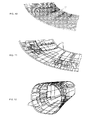
Figure 10 shows the geometric references in 2D obtained according to the present invention. -
Figures 11 and 12 show the fabric model generated by using the method of the present invention in 2D and in 3D. - The design of a composite material part is a complex process which, as shown in
Figure 1 , comprises afirst phase 11, in which the basic data of the laminate are specified taking into account the loads that it must support, a second phase 13 in which the fabric model is designed, athird phase 15 in which the producibility of the design is analyzed, a fourth phase 17 in which the design is possibly modified, in which case, the previous corresponding step is repeated to carry out the corresponding adjustments, and a final phase 19 in which the information required to manufacture the part is obtained. - In the context of this process, the present invention relates to the phase 13 for designing the fabric model of a curved surface part using a CAD system. In the known art, this phase is developed following the scheme of
Figure 2 . - The inputs of this phase are:
- The geometry of the surface of the
curved part 21 on which the fabrics will be supported, which will be denominated support surface. - The representation geometry of the
structural entities 23, understanding that these are parts which will be joined to the curved part and the situation of which must be considered in the design of the fabric model. Said structural entities are, for example, stiffening elements of the curved part such as the frames or stringers used in aeronautic structures and the representation geometry thereof consists of planes or other surfaces intercepting the support surface. - Specifications of the
laminate 25, indicating to the designer how the contours of the fabrics must be located on the support surface. - Based on said
geometries first step 27, which references basically consist of the intersections of the structural entities with the support surface and in curves parallel thereto. - From said references, the design of the fabric model in 3D, i.e. the definition of the contours of the different fabrics forming the laminate of the part, is carried out in a
second step 29. - In the method according to the present invention, the phase for designing the fabric model is developed by following the scheme of
Figure 3 which will be explained in detail below in relation to an embodiment of the invention applied to a tubular curved part stiffened with transverse frames and longitudinal stringers. - The starting data are the same as those used in the known art: the geometry of the
support surface 21, the geometry of the structural entities 23 (i.e. the frames and the stringers) and the specifications of thelaminate 25. - In a
first step 31, the 3D references are generated by means of the following steps: - a) The intersections between the planes of the structural entities with the support surface are created. This will give rise to an intersection curve 51 for each structural entity (see
Figure 4 ). - b) As many raised surfaces per intersection created in the previous step are created, such that a line will be scanned, taking the intersection itself as the spine. The
resulting surfaces 53 may be normal to the support surface or coincide with the plane of the rising structural entity (seeFigure 5 ). - In a
second step 33, the curved surface is developed in a plane. i.e. in 2D, by means of the following steps: - a) The outer contour 55 of the support surface is created and the
development plane 56 is created (seeFigure 6 ). - b) The
contour 57 is developed on thedevelopment plane 56 using reference point 54 (seeFigure 6 ). - In a
third step 35, the 3D to 2D references are developed by means of the following steps: - a) All the intersections of the structural entities with the support surface are developed on the
development plane 56. - b) As many raised
surfaces 59 per intersection developed in the previous step are created, such that a line will be scanned, taking the developed curve itself as the spine. The resulting surfaces will be normal to thedevelopment plane 56. These surfaces can also be obtained by means of the extrusion of the developed curves taking the normal of thedevelopment plane 56 as the direction (seeFigure 7 ). - In a fourth step 37, each 3D reference is associated with its corresponding 2D reference by means of the following steps:
- a) Joints are created in twos between the raised surfaces 53, 59 obtained in 3D and 2D. The result will be a composite surface 61 with two domains, one in 3D and the other in 2D, per structural entity (see
Figure 8 ). - b) A
planar surface 63, asupport surface replica 65 on which the new surfaces will be supported, as well as acurve 67 which in turn intercepts theplanar surface 63 and thesupport surface replica 65 are created by filling the outer contour developed in step b). The intersection point 69 will be the switch changing the references between the 2D domain and the 3D domain. Out of the two domains contained in the composite surface, the one closest to point 69 will be activated. If working in 2D is desired, the intersection with theplanar surface 63 will be calculated. If working in 3D is desired, the intersection with thesupport surface replica 65 will be calculated. This point 69 will be the geometric reference causing the selection of one domain or the other (2D or 3D) as the generating entity while creating the contours of the fabrics. The 2D domain of the composite surface 61 is isolated if it is desired to work in a plane. The 3D domain of the composite surface 61 is isolated if it is desired to work in a curve, substituting theplanar surface 63 with the support surface replica 65 (seeFigure 9 ). - c) References 71 are created in 2D (see
Figure 10 ). - In a
fifth step 39, thecontours 75 of the fabrics are created in 2D (seeFigure 11 ). - In a
sixth step 41, the fabric model is passed into the 3D environment (seeFigure 12 ). - In an optional
seventh step 41, the fabric model can be modified both in the 2D environment and in the 3D environment. - As deduced from the foregoing, the basic principle of the method according to the present invention consists of preparing the same starting information in the 3D and in the 2d environment for the purpose of generating references 51, 71 in 3D and in 2D respectively, and of being able to change from one environment to the other according to the needs of the designer.
- To implement the method, a series of computer tools is used together with a conventional CAD system or a system included therein, which computer tools carry out the mentioned operations and particularly those relating to:
- Developing in 2D the geometries of the curved surface and of the structural entities.
- Using the mentioned composite surface by activating the 3D domain or the 2D domain in order to work in either one.
- Updating the CAD system with the information resulting from the work in any of said domains.
- The present invention is applicable to both "developable" curved surface and to "non-developable" curved surfaces in the strictly mathematical sense of these terms. In this sense and as will be understood by persons skilled in the art, one of the known methods of "flattening" "non-developable" surfaces can be used in the case of "non-developable" surfaces in the generation of the 2D environment.
- Those modifications comprised within the scope defined by the following claims can be introduced in the preferred embodiment which has just been described.
Claims (4)
- A method for designing a composite material part with a curved surface (65) to which a plurality of stiffening elements oriented in planes considerably perpendicular to said curved surface are joined, including the design of a 3D fabric model defining the contours of the fabrics which must be stacked to shape said part from the geometric references relating to said part with a curved surface (65) and to said stiffening parts, characterized in that said design of the 3D fabric model comprises the following steps:- generating a planar surface (63) developed in 2D of the surface (65) of the curved part as well as the same geometric references (71) in 2D as the references (51) of the curved surface in 3D;- associating the surface (63) developed in 2D and the curved surface (65) in 3D as well as their geometric references (71, 51), such that any action in one of them is reflected in the other;- initially computing the fabric model in the surface (63) developed in 2D;- carrying out any subsequent modification of the fabric model either in the surface (63) developed in 2D or in the curved surface (65) in 3D.
- A method for designing a composite material part with a curved surface (65) according to claim 1, characterized in that the association between the mentioned elements is carried out by creating a composite surface (61) with a 2D domain and a 3D domain for each stiffening part.
- A method for designing a composite material part with a curved surface (65) according to claim 1, characterized in that the part with a curved surface is tubular and the stiffening parts consists of transverse frames and longitudinal stringers.
- A data medium in which program instructions are stored, characterized in that it causes the implementation of the method object of any of claims 1-3 when it is executed in a computer together with a CAD system or a system included therein.
Applications Claiming Priority (1)
| Application Number | Priority Date | Filing Date | Title |
|---|---|---|---|
| PCT/ES2007/070038 WO2008104613A2 (en) | 2007-02-27 | 2007-02-27 | Method for designing part made from composite material and having a curved surface |
Publications (2)
| Publication Number | Publication Date |
|---|---|
| EP2128777A2 true EP2128777A2 (en) | 2009-12-02 |
| EP2128777A4 EP2128777A4 (en) | 2014-03-19 |
Family
ID=39716901
Family Applications (1)
| Application Number | Title | Priority Date | Filing Date |
|---|---|---|---|
| EP07730481.4A Withdrawn EP2128777A4 (en) | 2007-02-27 | 2007-02-27 | METHOD FOR DESIGNING A CURVED SURFACE COMPOSITE MATERIAL PART |
Country Status (4)
| Country | Link |
|---|---|
| US (1) | US8751197B2 (en) |
| EP (1) | EP2128777A4 (en) |
| CN (1) | CN101689211B (en) |
| WO (1) | WO2008104613A2 (en) |
Cited By (1)
| Publication number | Priority date | Publication date | Assignee | Title |
|---|---|---|---|---|
| CN102254066A (en) * | 2011-06-30 | 2011-11-23 | 西北工业大学 | Collaborative optimization design method for curved surface shape and pore shape in pored thin-wall curved shell structure |
Families Citing this family (15)
| Publication number | Priority date | Publication date | Assignee | Title |
|---|---|---|---|---|
| US9002681B2 (en) * | 2009-05-13 | 2015-04-07 | Airbus Operations S.L. | Computer-assisted method for optimising surfaces of composite-material structures |
| CN101719187B (en) * | 2009-12-23 | 2011-08-24 | 西北工业大学 | Hole optimizing design method for porous thin wall rotating curved surface structure |
| EP2526501A4 (en) * | 2010-01-21 | 2017-09-20 | Firehole Technologies | Automated method to determine composite material constituent properties |
| CN101840452B (en) * | 2010-04-22 | 2012-06-27 | 西北工业大学 | Space hole optimization design method of thin-wall curved-surface structure with holes |
| CN102221444B (en) * | 2011-04-07 | 2013-08-14 | 西北工业大学 | Device for adjusting wing surface of wing wind tunnel blowing model and adjustment method |
| CA2867860A1 (en) * | 2012-04-02 | 2013-10-10 | William Anton TRONDL | Method of making a 3d object from composite material |
| CN102867082B (en) * | 2012-08-29 | 2015-04-22 | 西北工业大学 | Laying spreading method for composite material |
| EP3057805A4 (en) * | 2013-10-14 | 2017-07-12 | United Technologies Corporation | Automated laminate composite solid ply generation |
| JP6297955B2 (en) * | 2014-09-16 | 2018-03-20 | 株式会社Ihi | Design support apparatus, design support method, and program |
| US10062202B2 (en) * | 2014-12-22 | 2018-08-28 | General Electric Company | System and methods of generating a computer model of a composite component |
| US9582616B2 (en) * | 2015-01-23 | 2017-02-28 | Siemens Product Lifecycle Management Software Inc. | Method for representing and generating a flat pattern for a composite ply that folds over itself |
| US10345791B2 (en) * | 2015-09-21 | 2019-07-09 | Siemens Product Lifecycle Management Software Inc. | System and method for distributing multiple layers of a composite within a structural volume containing an inclusion |
| EP4550201A3 (en) * | 2017-12-22 | 2025-07-09 | Dassault Systèmes | Method for computing an unfolded part of a modeled bended part of a 3d object |
| CN115659690B (en) * | 2022-11-08 | 2023-06-30 | 哈尔滨工业大学 | Curved surface near zero stress acquisition method, curved surface near zero stress acquisition device, computer and storage medium |
| US20250353260A1 (en) * | 2024-05-14 | 2025-11-20 | The Boeing Company | Curve-wise surface flattening for composite layup |
Family Cites Families (5)
| Publication number | Priority date | Publication date | Assignee | Title |
|---|---|---|---|---|
| FR2766407B1 (en) * | 1997-07-22 | 1999-10-15 | Aerospatiale | PROCESS FOR MANUFACTURING LARGE-DIMENSIONAL PARTS IN COMPOSITE MATERIAL WITH A THERMOPLASTIC MATRIX, SUCH AS FUSELAGE TRUNKS OF AIRCRAFT |
| US6232980B1 (en) * | 1998-03-18 | 2001-05-15 | Silicon Graphics, Inc. | System and method for generating planar maps of three-dimensional surfaces |
| JP2005502111A (en) * | 2001-08-31 | 2005-01-20 | ソリッドワークス コーポレイション | Simultaneous use of 2D and 3D modeling data |
| US7369909B2 (en) * | 2003-04-30 | 2008-05-06 | Adrian Richard Marshall | Producing three-dimensional objects from deformable material |
| US6819966B1 (en) * | 2003-12-06 | 2004-11-16 | Paul E. Haeberli | Fabrication of free form structures from planar materials |
-
2007
- 2007-02-27 CN CN2007800527380A patent/CN101689211B/en not_active Expired - Fee Related
- 2007-02-27 WO PCT/ES2007/070038 patent/WO2008104613A2/en not_active Ceased
- 2007-02-27 EP EP07730481.4A patent/EP2128777A4/en not_active Withdrawn
- 2007-04-27 US US11/796,744 patent/US8751197B2/en not_active Expired - Fee Related
Cited By (2)
| Publication number | Priority date | Publication date | Assignee | Title |
|---|---|---|---|---|
| CN102254066A (en) * | 2011-06-30 | 2011-11-23 | 西北工业大学 | Collaborative optimization design method for curved surface shape and pore shape in pored thin-wall curved shell structure |
| CN102254066B (en) * | 2011-06-30 | 2013-04-24 | 西北工业大学 | Collaborative optimization design method for curved surface shape and pore shape in pored thin-wall curved shell structure |
Also Published As
| Publication number | Publication date |
|---|---|
| WO2008104613A8 (en) | 2011-10-27 |
| WO2008104613A2 (en) | 2008-09-04 |
| US8751197B2 (en) | 2014-06-10 |
| US20080208540A1 (en) | 2008-08-28 |
| EP2128777A4 (en) | 2014-03-19 |
| CN101689211B (en) | 2013-03-27 |
| CN101689211A (en) | 2010-03-31 |
Similar Documents
| Publication | Publication Date | Title |
|---|---|---|
| US8751197B2 (en) | Method for designing a composite material part with a curved surface | |
| US7010472B1 (en) | Knowledge driven composite design optimization process and system therefor | |
| Ransom et al. | Global/local stress analysis of composite panels | |
| Xu et al. | CAD‐based shape optimisation with CFD using a discrete adjoint | |
| Vanderplaats | Structural optimization-past, present, and future | |
| US5984511A (en) | Knowledge driven composite design optimization process and system therefor | |
| US8655627B2 (en) | Determining a distribution of multiple layers of a composite material within a structural volume | |
| Lee et al. | CASCAM—an automated system for sculptured surface cavity machining | |
| EP1050396B2 (en) | Knowledge driven composite design optimization process and system therefor | |
| CN102096736A (en) | Asymptotic variational method-based method for simulating and optimizing composite material laminated plate | |
| De Miguel et al. | Free-edge stress fields in generic laminated composites via higher-order kinematics | |
| Hancock et al. | Inverse drape modelling—an investigation of the set of shapes that can be formed from continuous aligned woven fibre reinforcements | |
| Längst et al. | The potentials of isogeometric analysis methods in integrated design processes | |
| Tapie et al. | Topological model for machining of parts with complex shapes | |
| Morris et al. | Domain-element method for aerodynamic shape optimization applied to modern transport wing | |
| Van Tooren et al. | Optimization of variable stiffness composite plates with cut-outs subjected to compression, tension and shear using an adjoint formulation | |
| Gray et al. | Aerostructural optimization of the simple transonic wing using MPhys, ADflow, and TACS | |
| Choi et al. | A knowledge‐based engineering tool to estimate cost and weight of composite aerospace structures at the conceptual stage of the design process | |
| Bhooshan et al. | Design workflow for additive manufacturing: a comparative study | |
| Bhooshan et al. | 3D-printing, topology optimization and statistical learning: a case study | |
| Schueler et al. | Object-oriented implementation of an integrated design and analysis tool for fiber placed structures | |
| Chinta et al. | A new design and analysis of BUS body structure | |
| Petrzelka et al. | Advanced process planning for subtractive rapid prototyping | |
| Roh et al. | Improvement of ship design practice using a 3D CAD model of a hull structure | |
| Morris et al. | Aerodynamic shape optimization of a modern transport wing using only planform variations |
Legal Events
| Date | Code | Title | Description |
|---|---|---|---|
| PUAI | Public reference made under article 153(3) epc to a published international application that has entered the european phase |
Free format text: ORIGINAL CODE: 0009012 |
|
| 17P | Request for examination filed |
Effective date: 20090918 |
|
| AK | Designated contracting states |
Kind code of ref document: A2 Designated state(s): AT BE BG CH CY CZ DE DK EE ES FI FR GB GR HU IE IS IT LI LT LU LV MC NL PL PT RO SE SI SK TR |
|
| DAX | Request for extension of the european patent (deleted) | ||
| R17D | Deferred search report published (corrected) |
Effective date: 20080904 |
|
| RIN1 | Information on inventor provided before grant (corrected) |
Inventor name: BURGOS GALLEGO, RAUL Inventor name: VILLARRUBIA CORTES, JOSE |
|
| A4 | Supplementary search report drawn up and despatched |
Effective date: 20140219 |
|
| RIC1 | Information provided on ipc code assigned before grant |
Ipc: G06F 17/50 20060101AFI20140213BHEP |
|
| RAP1 | Party data changed (applicant data changed or rights of an application transferred) |
Owner name: AIRBUS OPERATIONS S.L. |
|
| STAA | Information on the status of an ep patent application or granted ep patent |
Free format text: STATUS: THE APPLICATION HAS BEEN WITHDRAWN |
|
| 18W | Application withdrawn |
Effective date: 20170120 |