EP2128544A1 - Refrigerant cycle and method for controlling the same - Google Patents
Refrigerant cycle and method for controlling the same Download PDFInfo
- Publication number
- EP2128544A1 EP2128544A1 EP08711570A EP08711570A EP2128544A1 EP 2128544 A1 EP2128544 A1 EP 2128544A1 EP 08711570 A EP08711570 A EP 08711570A EP 08711570 A EP08711570 A EP 08711570A EP 2128544 A1 EP2128544 A1 EP 2128544A1
- Authority
- EP
- European Patent Office
- Prior art keywords
- instruction
- amount
- electrical noise
- case
- driving
- Prior art date
- Legal status (The legal status is an assumption and is not a legal conclusion. Google has not performed a legal analysis and makes no representation as to the accuracy of the status listed.)
- Withdrawn
Links
- 239000003507 refrigerant Substances 0.000 title claims abstract description 49
- 238000000034 method Methods 0.000 title claims description 29
- 230000008569 process Effects 0.000 description 7
- 230000008859 change Effects 0.000 description 4
- 238000010586 diagram Methods 0.000 description 4
- 239000007788 liquid Substances 0.000 description 4
- 238000005259 measurement Methods 0.000 description 2
- 230000000694 effects Effects 0.000 description 1
- 239000000463 material Substances 0.000 description 1
- 238000012986 modification Methods 0.000 description 1
- 230000004048 modification Effects 0.000 description 1
- 230000004044 response Effects 0.000 description 1
Images


Classifications
-
- F—MECHANICAL ENGINEERING; LIGHTING; HEATING; WEAPONS; BLASTING
- F25—REFRIGERATION OR COOLING; COMBINED HEATING AND REFRIGERATION SYSTEMS; HEAT PUMP SYSTEMS; MANUFACTURE OR STORAGE OF ICE; LIQUEFACTION SOLIDIFICATION OF GASES
- F25B—REFRIGERATION MACHINES, PLANTS OR SYSTEMS; COMBINED HEATING AND REFRIGERATION SYSTEMS; HEAT PUMP SYSTEMS
- F25B41/00—Fluid-circulation arrangements
- F25B41/30—Expansion means; Dispositions thereof
- F25B41/31—Expansion valves
- F25B41/34—Expansion valves with the valve member being actuated by electric means, e.g. by piezoelectric actuators
- F25B41/345—Expansion valves with the valve member being actuated by electric means, e.g. by piezoelectric actuators by solenoids
- F25B41/347—Expansion valves with the valve member being actuated by electric means, e.g. by piezoelectric actuators by solenoids with the valve member being opened and closed cyclically, e.g. with pulse width modulation
-
- F—MECHANICAL ENGINEERING; LIGHTING; HEATING; WEAPONS; BLASTING
- F25—REFRIGERATION OR COOLING; COMBINED HEATING AND REFRIGERATION SYSTEMS; HEAT PUMP SYSTEMS; MANUFACTURE OR STORAGE OF ICE; LIQUEFACTION SOLIDIFICATION OF GASES
- F25B—REFRIGERATION MACHINES, PLANTS OR SYSTEMS; COMBINED HEATING AND REFRIGERATION SYSTEMS; HEAT PUMP SYSTEMS
- F25B2500/00—Problems to be solved
- F25B2500/12—Sound
-
- F—MECHANICAL ENGINEERING; LIGHTING; HEATING; WEAPONS; BLASTING
- F25—REFRIGERATION OR COOLING; COMBINED HEATING AND REFRIGERATION SYSTEMS; HEAT PUMP SYSTEMS; MANUFACTURE OR STORAGE OF ICE; LIQUEFACTION SOLIDIFICATION OF GASES
- F25B—REFRIGERATION MACHINES, PLANTS OR SYSTEMS; COMBINED HEATING AND REFRIGERATION SYSTEMS; HEAT PUMP SYSTEMS
- F25B2600/00—Control issues
- F25B2600/25—Control of valves
- F25B2600/2513—Expansion valves
-
- Y—GENERAL TAGGING OF NEW TECHNOLOGICAL DEVELOPMENTS; GENERAL TAGGING OF CROSS-SECTIONAL TECHNOLOGIES SPANNING OVER SEVERAL SECTIONS OF THE IPC; TECHNICAL SUBJECTS COVERED BY FORMER USPC CROSS-REFERENCE ART COLLECTIONS [XRACs] AND DIGESTS
- Y02—TECHNOLOGIES OR APPLICATIONS FOR MITIGATION OR ADAPTATION AGAINST CLIMATE CHANGE
- Y02B—CLIMATE CHANGE MITIGATION TECHNOLOGIES RELATED TO BUILDINGS, e.g. HOUSING, HOUSE APPLIANCES OR RELATED END-USER APPLICATIONS
- Y02B30/00—Energy efficient heating, ventilation or air conditioning [HVAC]
- Y02B30/70—Efficient control or regulation technologies, e.g. for control of refrigerant flow, motor or heating
Definitions
- the present invention relates to a refrigerant cycle and a method of controlling the same.
- Patent Document 1 describes a technique of changing a structure of an expansion valve to reduce cavitation noise.
- Patent Document 1 Japanese Patent Application Laid-Open No. 09-133434
- a first aspect of the method of controlling a refrigerant cycle of the present invention relates to a method of controlling a refrigerant cycle which includes: a compressor (101), a condenser (103), an expansion valve (107), and an evaporator (202) through which a refrigerant (LG, HG, HL, LL, LG) circulates in the stated order; and a control section (106) which controls, based on a first instruction (C) for setting temperature control, at least an operation of the compressor, and an interval (T) and a driving amount (J) for driving the expansion valve.
- the method executes the steps of: (a) obtaining a second instruction (Q) for setting whether or not a countermeasure against electrical noise is taken (S12); (b) adopting, in a case where the second instruction indicates that the countermeasure against electrical noise is not taken, a first value (D1) as the interval based on the first instruction (S13); (c) adopting, in a case where the second instruction indicates that the countermeasure against electrical noise is taken, a second value (D2) larger than the first interval as the interval (S14); and (d) transmitting, after the steps (b) and (c) are performed, the driving amount to the expansion valve at the interval (S19).
- the control section (106) generates an instruction amount (E) serving as a target value of the driving amount (J), and the method further executes, between the step (a) and the step (d), the steps of: (e) judging, in a case where the second instruction indicates that the countermeasure against electrical noise is taken, whether or not the instruction amount exceeds a predetermined value (P) (15); (f) adopting, in a case where the judgment of the step (e) is negative, the instruction amount as the driving amount (S16); and (g) adopting, in a case where the judgment of the step (e) is affirmative, a value smaller than the instruction amount as the driving amount (S 17).
- step (d) executed are: (d-1) adopting, in the case where the second instruction indicates that the countermeasure against electrical noise is not taken, the instruction amount as the driving amount (S16) and transmitting the driving amount to the expansion valve (S19); and (d-2) transmitting, in the case where the second instruction indicates that the countermeasure against electrical noise is taken, the driving amount adopted in any one of the steps (f) and (g) to the expansion valve (S19).
- the method further executes the step of (h) subtracting the driving amount adopted in the step (g) from the indication value and updating the indication value, the step (h) (S18) being accompanied with the step (g) and performed, wherein the steps (a) to (h) are performed again.
- the refrigerant cycle includes: a compressor (101), a condenser (103), an expansion valve (107), and an evaporator (202) through which a refrigerant (LG, HG, HL, LL, LG) circulates in the stated order; a control signal generating section (106f) which generates, based on a first instruction (C) for setting temperature control, a control signal (M) for controlling an operation of the compressor; an interval generating section (106b) which receives a second instruction (Q) indicating whether or not a countermeasure against electrical noise is taken, (i) sets an interval for driving the expansion valve as a first value (D1) based on the first instruction in a case where the second instruction indicates that the countermeasure against electrical noise is not taken, and (ii) sets the interval as a second value (D2) larger than the first interval in a case where the second instruction indicates that the countermeasure against electrical noise is taken; and an output section (106
- the refrigerant cycle further includes: a driving instruction amount generating section (106a) which generates, based on the first instruction, an instruction amount (E) serving as a target value of the driving amount (J); and a driving amount generating section (106c) which receives the instruction amount (E) and the second instruction (Q), (I) adopts the instruction amount as the driving amount (J) and transmits it to the output section (106d) in the case where the second instruction indicates that the countermeasure against electrical noise is taken and in a case where the instruction amount does not exceed a predetermined value (P), and (II) adopts a value smaller than the instruction amount as the driving amount and transmits it to the output section (106d) in the case where the second instruction indicates that the countermeasure against electrical noise is taken and in a case where the instruction amount exceeds the predetermined value.
- a driving instruction amount generating section (106a) which generates, based on the first instruction, an instruction amount (E) serving as a target value of the driving amount (J); and a
- the driving amount generating section (106c) (III) adopts the instruction amount as the driving amount (J) and transmits it to the output section (106d) in the case where the second instruction indicates that the countermeasure against electrical noise is not taken.
- the interval for driving the expansion valve is increased when the countermeasure against electrical noise is taken. Accordingly, the flow of the refrigerant is made slow, whereby it is possible to reduce the generated electrical noise while performing the temperature control based on the first instruction.
- the driving amount for driving the expansion valve is reduced when the countermeasure against electrical noise is taken. Accordingly, the flow of the refrigerant is made slow, whereby it is possible to reduce the generated electrical noise while performing the temperature control based on the first instruction.
- the driving amount reduced in the second aspects is compensated.
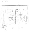
- FIG. 1 is a block diagram showing a refrigerant cycle according to the present invention.
- the refrigerant cycle is realized by an air conditioner, and the air conditioner includes an outdoor unit 1 and an indoor unit 2.
- a refrigerant circulates through a compressor 101, a condenser 103, an expansion valve 107, and an evaporator 202 in the stated order.
- a low-pressure gaseous refrigerant LG is compressed by the compressor 101 to become a high-pressure gaseous refrigerant HG
- the gaseous refrigerant HG is condensed by the condenser 103 to become a high-pressure liquid refrigerant HL
- the liquid refrigerant HL is expanded by the expansion valve 107 to become a low-pressure liquid refrigerant LL
- the liquid refrigerant LL is evaporated by the evaporator 202 to become a gaseous refrigerant LG.
- the compressor 101 is driven by a motor 102. Air is send to the condenser 103 by a fan, and the fan 104 is driven by a motor 105. Air is send to the evaporator 202 by a fan 203, and the fan 203 is driven by a motor 204.
- the outdoor unit 1 includes the compressor 101, the motor 102, the condenser 103, the fan 104, the motor 105, a control section 106, and the expansion valve 107.
- the indoor unit 2 includes a control section 201, the evaporator 202, the fan 203, and the motor 204.
- the control section 106 outputs, based on a first instruction C from outside for setting temperature control, control signals M, F1, and F2 for controlling rotation of the motor 102, 105, and 204, respectively.
- the control section 106 outputs a driving pulse J for controlling a driving amount of the expansion valve 107 at intervals described below.
- the driving pulse J and its output intervals are adopted based on a second instruction Q for externally setting whether or not a countermeasure against electrical noise is taken.
- FIG. 2 is a flowchart illustrating a method of controlling the refrigerant cycle according to the present invention.
- FIG. 3 is a block diagram illustrating functions of the control section 106 by way of blocks 106a to 106f. The blocks shown in FIG. 3 are not necessarily realized by hardware.
- the control section 106 is composed of an arithmetic processing unit provided with an interface as required. The functions which correspond to those of the blocks shown in FIG. 3 may be performed in the arithmetic processing unit by a program.
- Step S11 of FIG. 2 it is judged in Step S11 of FIG. 2 whether or not a timing to drive the expansion valve 107 has arrived. In other words, it is judged whether or not an interval which corresponds to a drive timing has passed. This is shown as a function of a timer 106e in FIG. 3 . That is, this corresponds to a fact that an output section 106d which outputs the driving pulse J checks the timer 106e whether the drive timing (interval) has passed.
- Step S11 control of the refrigerant cycle returns to a main routine (not shown).
- drive control of the motors 102, 105, and 204 is executed in response to the control signals M, F1, and F2, respectively.
- Step S11 If the judgment of Step S11 is affirmative, the control of the refrigerant cycle proceeds to Step S19 via Steps S12 through S 18, whereby the driving pulse J is output.
- Step S19 corresponds to, in FIG. 3 , responding to checking from the block 106d to the timer 106e and permitting or instructing, by the timer 106e, an output of the driving pulse J from the output section 106d (corresponding to an affirmative judgment), or prohibiting or not instructing the output of the driving pulse J (corresponding to a negative judgment).
- the output section 106d transmits the driving pulse J to the expansion valve 107 at an interval serving as the drive timing.
- Step S12 it is judged in Step S12 whether or not the countermeasure against the generated electrical noise is taken.
- the process proceeds to Step S13 in the case where the countermeasure is not taken, whereas the process proceeds to Step S14 in the case where the countermeasure is taken.
- a signal which takes a binary logic is adopted as the second instruction Q, and the binary logic is caused to respond to whether or not the countermeasure against the generated electrical noise is taken.
- Step S13 a first value D1 is adopted as the drive timing to output the driving pulse J.
- Step S14 a second value D2 is adopted as the drive timing to output the driving pulse J.
- the driving pulse J is output at the drive timings at which respective values are adopted (that is, at intervals corresponding to the respective values) after any of Steps S13 and S14 is performed to be output to the expansion valve 107.
- the values D1 and D2 also depend on the first instruction C as described below, the value D2 is larger than the value D1 if there are no fluctuations in the first instruction C.
- the first instruction C and the second instruction Q are transmitted to an interval generating section 106 which generates the drive timing, and any of the values D1 and D2 is generated as a drive timing T to be transmitted to the timer 106e. After that, the timer 106e times the transmitted drive timing T.
- an interval generating section 106b can adopt the values D1 and D2 generated in advance as the drive timing T, instead of generating the values D1 and D2.
- the drive timing T fluctuates in accordance with setting of temperature control indicated by the first instruction C. For example, if a rapid temperature change is set by the first instruction C, a value taken by the drive timing T is small, whereby the expansion valve 107 is frequently driven. In such a case, however, the value D2 in a case where an instruction to take the countermeasure against electrical noise generated is issued by the second instruction Q is larger than the value D1 in a case where the instruction is not issued.
- the driving pulse J is generated based on an instruction pulse E and the second instruction Q. Since the instruction pulse E is generated based on the first instruction C, it can also be considered that the driving pulse J is generated based on the first instruction C and the second instruction Q.
- the instruction pulse E is generated in accordance with the setting of temperature control, which is indicated by the first instruction C.
- the instruction pulse E is a target value of the driving pulse J, and becomes the driving pulse J when the countermeasure against electrical noise is not taken.
- Step S16 the process proceeds to Step S16 after the execution of Step S13, where the instruction pulse E is adopted as the driving pulse J.
- Step S19 the driving pulse J is transmitted to the expansion valve 107.
- the instruction pulse E is not necessarily adopted directly as the driving pulse J.
- Step S15 it is judged in Step S15 whether or not the instruction pulse E exceeds a predetermined value P. In a case where the judgment of Step S15 is negative, the process proceeds to Step S16, and the instruction pulse E is adopted as the driving pulse J. In a case where the judgment of Step S15 is affirmative, the process proceeds to Step S17, and a value smaller than the instruction pulse E is adopted as the driving pulse J.
- the predetermined value P is adopted a value of the driving pulse J is described as an example.
- the instruction pulse E and the second instruction Q are input to a driving amount generating section 106c. Then, in a case where the second instruction Q indicates that the countermeasure against electrical noise is taken and the instruction pulse E does not exceed the predetermined value P, the driving amount generating section 106c adopts the instruction pulse E as the driving pulse J and transmits it to the output section 106. Meanwhile, in a case where the second instruction Q indicates that the countermeasure against electrical noise is taken and the instruction pulse E exceeds the predetermined value P, the driving amount generating section 106c adopts a value smaller than the instruction pulse E as the driving pulse J and transmits it to the output section 106d.
- the driving pulse J transmitted to the output section 106d is transmitted to the expansion valve 107 (Step S19).
- the driving pulse J is set to the predetermined value P.
- Step S18 is desirably performed.
- the driving pulse J in Step S17, the predetermined value P is adopted
- Step S 19 is performed.
- the instruction pulse E is modified in this manner, and hence, when the flowchart of FIG. 3 is performed at a following drive timing, it is possible to compensate a driving amount which is insufficient in a value (predetermined value P in the example described above) adopted as the driving pulse J in Step S17 previously.
- the instruction pulse E is modified in the driving amount generating section 106c. Note that in a case where Step S 17 is not performed but Step S16 is performed, the driving amount generating section 106c maintains the instruction pulse E.
- Step S 18 may be omitted.
- Step S12 to S19 are performed based on the instruction pulse E generated for each drive timing, the above-mentioned omission is possible.
- a control signal generating section 106f is also provided in the control section 106.
- the control signal generating section 106f generates a control signal M based on the first instruction C for controlling an operation of the motor 102 which indirectly controls the compressor 101.
- the control signals F1 and F2 for controlling the motors 105 and 204, respectively, are also generated by the control signal generating section 106f.
- the control signal F2 is provided to the control section 201 and indirectly controls driving of the motor 204 through a process of the control section 201.
Landscapes
- Engineering & Computer Science (AREA)
- Physics & Mathematics (AREA)
- Mechanical Engineering (AREA)
- Thermal Sciences (AREA)
- General Engineering & Computer Science (AREA)
- Air Conditioning Control Device (AREA)
- Air-Conditioning For Vehicles (AREA)
- Control Of Temperature (AREA)
- Compression-Type Refrigeration Machines With Reversible Cycles (AREA)
- Electrically Driven Valve-Operating Means (AREA)
Abstract
An object of the present invention is to reduce electrical noise in accordance with the necessity of a countermeasure taken against electrical noise without changing a structure of an expansion valve. In a case where a judgment result as to whether or not the countermeasure against electrical noise is taken is affirmative, a drive timing (interval) of an expansion valve (107) is increased. Further, a driving amount is reduced. Accordingly, a flow of a refrigerant is made slow, whereby it is possible to reduce generated electrical noise while performing instructed temperature control.
Description
- The present invention relates to a refrigerant cycle and a method of controlling the same.
- When a refrigerant cycle is driven, it is required to satisfy standards by reducing generated noise, in particular, electrical noise. For instance, in our country, described in the provision in
Section 2 of the ministerial ordinance of Electrical Appliances and Material Safety Law, more specifically, there are so-called IEC-J standards J55001 (Standard for Noise Intensity), J55014-1 (Electromagnetic Compatibility-Requirement for Household Appliances, Electric Tools and Similar Apparatus), and J55022 (Information from Technology Equipment-Radio Disturbance Characteristics-Limits and Methods of Measurement). In Europe, there are EN55014-1 (Electromagnetic compatibility. Requirements for household appliances, electric tools and similar apparatus. Emission) and EN55022 (Information technology equipment. Radio disturbance characteristics. Limits and methods of measurement). Those standards do not need to be satisfied all the time, and it is sufficient only to reduce electrical noise under conditions set in advance. That is, the refrigerant cycle is required to perform an operation for satisfying the standards in a case where the standards need to be satisfied, and perform another operation in a case where the standards do not need to be satisfied. - In order to reduce the generation of electrical noise, it is conceivable to, for example, change a structure of an expansion valve.
- Note that
Patent Document 1 describes a technique of changing a structure of an expansion valve to reduce cavitation noise. - Patent Document 1: Japanese Patent Application Laid-Open No.
09-133434 - However, a change in structure of the expansion valve leads to a rise in cost. In addition, it is cumbersome to change the structure of the expansion valve in accordance with the need as to whether the standards are satisfied.
- Therefore, in order to reduce the generation of electrical noise without changing the structure, it is also conceivable to reduce a rotation speed of a compressor or reduce a rotation speed of a fan of a heat exchanger. For such control, an operation of an inverter circuit which drives them is directly controlled.
- However, according to the standards on electrical noise, it is required to reduce electrical noise under a predetermined temperature control condition. Accordingly, it is difficult to satisfy the above-mentioned standards by reducing the rotation speed of the compressor or the fan.
- It is therefore an object of the present invention to reduce electrical noise, under a temperature controlled condition, in accordance with the necessity of taking countermeasure against electrical noise without changing a structure of an expansion valve.
- A first aspect of the method of controlling a refrigerant cycle of the present invention relates to a method of controlling a refrigerant cycle which includes: a compressor (101), a condenser (103), an expansion valve (107), and an evaporator (202) through which a refrigerant (LG, HG, HL, LL, LG) circulates in the stated order; and a control section (106) which controls, based on a first instruction (C) for setting temperature control, at least an operation of the compressor, and an interval (T) and a driving amount (J) for driving the expansion valve. The method executes the steps of: (a) obtaining a second instruction (Q) for setting whether or not a countermeasure against electrical noise is taken (S12); (b) adopting, in a case where the second instruction indicates that the countermeasure against electrical noise is not taken, a first value (D1) as the interval based on the first instruction (S13); (c) adopting, in a case where the second instruction indicates that the countermeasure against electrical noise is taken, a second value (D2) larger than the first interval as the interval (S14); and (d) transmitting, after the steps (b) and (c) are performed, the driving amount to the expansion valve at the interval (S19).
- According to a second aspect of the method of controlling a refrigerant cycle of the present invention, in the first aspect, the control section (106) generates an instruction amount (E) serving as a target value of the driving amount (J), and the method further executes, between the step (a) and the step (d), the steps of: (e) judging, in a case where the second instruction indicates that the countermeasure against electrical noise is taken, whether or not the instruction amount exceeds a predetermined value (P) (15); (f) adopting, in a case where the judgment of the step (e) is negative, the instruction amount as the driving amount (S16); and (g) adopting, in a case where the judgment of the step (e) is affirmative, a value smaller than the instruction amount as the driving amount (S 17). In the step (d) executed are: (d-1) adopting, in the case where the second instruction indicates that the countermeasure against electrical noise is not taken, the instruction amount as the driving amount (S16) and transmitting the driving amount to the expansion valve (S19); and (d-2) transmitting, in the case where the second instruction indicates that the countermeasure against electrical noise is taken, the driving amount adopted in any one of the steps (f) and (g) to the expansion valve (S19).
- According to a third aspect of the method of controlling a refrigerant cycle of the present invention, in the second aspect, the method further executes the step of (h) subtracting the driving amount adopted in the step (g) from the indication value and updating the indication value, the step (h) (S18) being accompanied with the step (g) and performed, wherein the steps (a) to (h) are performed again.
- According to a first aspect of a refrigerant cycle of the present invention, the refrigerant cycle includes: a compressor (101), a condenser (103), an expansion valve (107), and an evaporator (202) through which a refrigerant (LG, HG, HL, LL, LG) circulates in the stated order; a control signal generating section (106f) which generates, based on a first instruction (C) for setting temperature control, a control signal (M) for controlling an operation of the compressor; an interval generating section (106b) which receives a second instruction (Q) indicating whether or not a countermeasure against electrical noise is taken, (i) sets an interval for driving the expansion valve as a first value (D1) based on the first instruction in a case where the second instruction indicates that the countermeasure against electrical noise is not taken, and (ii) sets the interval as a second value (D2) larger than the first interval in a case where the second instruction indicates that the countermeasure against electrical noise is taken; and an output section (106d) which transmits, based on the interval, a driving amount (J) for driving the expansion valve based on the first instruction, to the expansion valve.
- According to a second aspect of the refrigerant cycle of the present invention, in the first aspect, the refrigerant cycle further includes: a driving instruction amount generating section (106a) which generates, based on the first instruction, an instruction amount (E) serving as a target value of the driving amount (J); and a driving amount generating section (106c) which receives the instruction amount (E) and the second instruction (Q), (I) adopts the instruction amount as the driving amount (J) and transmits it to the output section (106d) in the case where the second instruction indicates that the countermeasure against electrical noise is taken and in a case where the instruction amount does not exceed a predetermined value (P), and (II) adopts a value smaller than the instruction amount as the driving amount and transmits it to the output section (106d) in the case where the second instruction indicates that the countermeasure against electrical noise is taken and in a case where the instruction amount exceeds the predetermined value.
- According to a third aspect of the refrigerant cycle of the present invention, in the second aspect, the driving amount generating section (106c) (III) adopts the instruction amount as the driving amount (J) and transmits it to the output section (106d) in the case where the second instruction indicates that the countermeasure against electrical noise is not taken.
- According to any of the first aspects of the refrigerant cycle and the method of controlling the same of the present invention, the interval for driving the expansion valve is increased when the countermeasure against electrical noise is taken. Accordingly, the flow of the refrigerant is made slow, whereby it is possible to reduce the generated electrical noise while performing the temperature control based on the first instruction.
- According to any of the second aspects of the refrigerant cycle and the method of controlling the same of the present invention, the driving amount for driving the expansion valve is reduced when the countermeasure against electrical noise is taken. Accordingly, the flow of the refrigerant is made slow, whereby it is possible to reduce the generated electrical noise while performing the temperature control based on the first instruction.
- According to any of the third aspects of the refrigerant cycle and the method of controlling the same of the present invention, the driving amount reduced in the second aspects is compensated.
- These and other objects, features, aspects and advantages of the present invention will become more apparent from the following detailed description of the present invention when taken in conjunction with the accompanying drawings.
-
- [
FIG. 1 ] A block diagram showing a refrigerant cycle according to the present invention. - [
FIG. 2 ] A flowchart illustrating a method of controlling the refrigerant cycle according to the present invention. - [
FIG. 3 ] A block diagram illustrating functions of a control section by way of blocks. -
FIG. 1 is a block diagram showing a refrigerant cycle according to the present invention. The refrigerant cycle is realized by an air conditioner, and the air conditioner includes anoutdoor unit 1 and anindoor unit 2. - In the refrigerant cycle, a refrigerant circulates through a
compressor 101, acondenser 103, anexpansion valve 107, and anevaporator 202 in the stated order. Specifically, a low-pressure gaseous refrigerant LG is compressed by thecompressor 101 to become a high-pressure gaseous refrigerant HG, the gaseous refrigerant HG is condensed by thecondenser 103 to become a high-pressure liquid refrigerant HL, the liquid refrigerant HL is expanded by theexpansion valve 107 to become a low-pressure liquid refrigerant LL, and the liquid refrigerant LL is evaporated by theevaporator 202 to become a gaseous refrigerant LG. - The
compressor 101 is driven by amotor 102. Air is send to thecondenser 103 by a fan, and thefan 104 is driven by amotor 105. Air is send to theevaporator 202 by afan 203, and thefan 203 is driven by amotor 204. - The
outdoor unit 1 includes thecompressor 101, themotor 102, thecondenser 103, thefan 104, themotor 105, acontrol section 106, and theexpansion valve 107. Theindoor unit 2 includes acontrol section 201, theevaporator 202, thefan 203, and themotor 204. - The
control section 106 outputs, based on a first instruction C from outside for setting temperature control, control signals M, F1, and F2 for controlling rotation of themotor control section 106 outputs a driving pulse J for controlling a driving amount of theexpansion valve 107 at intervals described below. The driving pulse J and its output intervals are adopted based on a second instruction Q for externally setting whether or not a countermeasure against electrical noise is taken. -
FIG. 2 is a flowchart illustrating a method of controlling the refrigerant cycle according to the present invention.FIG. 3 is a block diagram illustrating functions of thecontrol section 106 by way of blocks 106a to 106f. The blocks shown inFIG. 3 are not necessarily realized by hardware. Thecontrol section 106 is composed of an arithmetic processing unit provided with an interface as required. The functions which correspond to those of the blocks shown inFIG. 3 may be performed in the arithmetic processing unit by a program. - First, it is judged in Step S11 of
FIG. 2 whether or not a timing to drive theexpansion valve 107 has arrived. In other words, it is judged whether or not an interval which corresponds to a drive timing has passed. This is shown as a function of atimer 106e inFIG. 3 . That is, this corresponds to a fact that anoutput section 106d which outputs the driving pulse J checks thetimer 106e whether the drive timing (interval) has passed. - If the judgment of Step S11 is negative, control of the refrigerant cycle returns to a main routine (not shown). For example, in the main routine, drive control of the
motors - If the judgment of Step S11 is affirmative, the control of the refrigerant cycle proceeds to Step S19 via Steps S12 through S 18, whereby the driving pulse J is output. This corresponds to, in
FIG. 3 , responding to checking from theblock 106d to thetimer 106e and permitting or instructing, by thetimer 106e, an output of the driving pulse J from theoutput section 106d (corresponding to an affirmative judgment), or prohibiting or not instructing the output of the driving pulse J (corresponding to a negative judgment). Accordingly, theoutput section 106d transmits the driving pulse J to theexpansion valve 107 at an interval serving as the drive timing. - Next, it is judged in Step S12 whether or not the countermeasure against the generated electrical noise is taken. The process proceeds to Step S13 in the case where the countermeasure is not taken, whereas the process proceeds to Step S14 in the case where the countermeasure is taken. For example, a signal which takes a binary logic is adopted as the second instruction Q, and the binary logic is caused to respond to whether or not the countermeasure against the generated electrical noise is taken.
- In Step S13, a first value D1 is adopted as the drive timing to output the driving pulse J. In Step S14, a second value D2 is adopted as the drive timing to output the driving pulse J. Then, the driving pulse J is output at the drive timings at which respective values are adopted (that is, at intervals corresponding to the respective values) after any of Steps S13 and S14 is performed to be output to the
expansion valve 107. Although the values D1 and D2 also depend on the first instruction C as described below, the value D2 is larger than the value D1 if there are no fluctuations in the first instruction C. - In
FIG. 3 , the first instruction C and the second instruction Q are transmitted to aninterval generating section 106 which generates the drive timing, and any of the values D1 and D2 is generated as a drive timing T to be transmitted to thetimer 106e. After that, thetimer 106e times the transmitted drive timing T. - It goes without saying that an
interval generating section 106b can adopt the values D1 and D2 generated in advance as the drive timing T, instead of generating the values D1 and D2. - The drive timing T fluctuates in accordance with setting of temperature control indicated by the first instruction C. For example, if a rapid temperature change is set by the first instruction C, a value taken by the drive timing T is small, whereby the
expansion valve 107 is frequently driven. In such a case, however, the value D2 in a case where an instruction to take the countermeasure against electrical noise generated is issued by the second instruction Q is larger than the value D1 in a case where the instruction is not issued. - In this manner, an interval at which the
expansion valve 107 is driven is increased when the countermeasure against electrical noise is taken. As a result, a flow of the refrigerant is made slow, whereby it is possible to reduce generated electrical noise while performing temperature control based on the first instruction C. - Incidentally, the driving pulse J is generated based on an instruction pulse E and the second instruction Q. Since the instruction pulse E is generated based on the first instruction C, it can also be considered that the driving pulse J is generated based on the first instruction C and the second instruction Q.
- More specifically, in a driving instruction amount generating section 106a, the instruction pulse E is generated in accordance with the setting of temperature control, which is indicated by the first instruction C. The instruction pulse E is a target value of the driving pulse J, and becomes the driving pulse J when the countermeasure against electrical noise is not taken. Referring to
FIG. 2 , the process proceeds to Step S16 after the execution of Step S13, where the instruction pulse E is adopted as the driving pulse J. After Step S16 is performed, the process proceeds to Step S19, and the driving pulse J is transmitted to theexpansion valve 107. - However, when the countermeasure against electrical noise is taken, the instruction pulse E is not necessarily adopted directly as the driving pulse J.
- First, it is judged in Step S15 whether or not the instruction pulse E exceeds a predetermined value P. In a case where the judgment of Step S15 is negative, the process proceeds to Step S16, and the instruction pulse E is adopted as the driving pulse J. In a case where the judgment of Step S15 is affirmative, the process proceeds to Step S17, and a value smaller than the instruction pulse E is adopted as the driving pulse J. Here, a case where the predetermined value P is adopted a value of the driving pulse J is described as an example.
- Referring to
FIG. 3 , the instruction pulse E and the second instruction Q are input to a drivingamount generating section 106c. Then, in a case where the second instruction Q indicates that the countermeasure against electrical noise is taken and the instruction pulse E does not exceed the predetermined value P, the drivingamount generating section 106c adopts the instruction pulse E as the driving pulse J and transmits it to theoutput section 106. Meanwhile, in a case where the second instruction Q indicates that the countermeasure against electrical noise is taken and the instruction pulse E exceeds the predetermined value P, the drivingamount generating section 106c adopts a value smaller than the instruction pulse E as the driving pulse J and transmits it to theoutput section 106d. - The driving pulse J transmitted to the
output section 106d is transmitted to the expansion valve 107 (Step S19). In this case, the driving pulse J is set to the predetermined value P. - In this manner, when the countermeasure against electrical noise is taken, a driving amount for driving the
expansion valve 107 is reduced, with the result that the flow of the refrigerant is made slow. Accordingly, it is possible to reduce generated electrical noise while performing temperature control based on the first instruction C. - Note that in a case where Step S17 is performed, Step S18 is desirably performed. In Step S18, the driving pulse J (in Step S17, the predetermined value P is adopted) is subtracting from the instruction pulse E to modify the instruction pulse E. Then,
Step S 19 is performed. - The instruction pulse E is modified in this manner, and hence, when the flowchart of
FIG. 3 is performed at a following drive timing, it is possible to compensate a driving amount which is insufficient in a value (predetermined value P in the example described above) adopted as the driving pulse J in Step S17 previously. - The instruction pulse E is modified in the driving
amount generating section 106c. Note that in a case whereStep S 17 is not performed but Step S16 is performed, the drivingamount generating section 106c maintains the instruction pulse E. - However, Step S 18 may be omitted. For example, in a case where Steps S12 to S19 are performed based on the instruction pulse E generated for each drive timing, the above-mentioned omission is possible.
- Note that a control signal generating section 106f is also provided in the
control section 106. The control signal generating section 106f generates a control signal M based on the first instruction C for controlling an operation of themotor 102 which indirectly controls thecompressor 101. In addition, the control signals F1 and F2 for controlling themotors control section 201 and indirectly controls driving of themotor 204 through a process of thecontrol section 201. - While the invention has been shown and described in detail, the foregoing description is in all aspects illustrative and not restrictive. It is therefore understood that numerous modifications and variations can be devised without departing from the scope of the invention.
Claims (6)
- A method of controlling a refrigerant cycle, the refrigerant cycle comprising:a compressor (101), a condenser (103), an expansion valve (107), and an evaporator (202) through which a refrigerant (LG, HG, HL, LL, LG) circulates in the stated order; anda control section (106) which controls, based on a first instruction (C) for setting temperature control, at least an operation of the compressor, and an interval (T) and a driving amount (J) for driving the expansion valve,the method executing the steps of:(a) obtaining a second instruction (Q) for setting whether or not a countermeasure against electrical noise is taken (S12);(b) adopting, in a case where the second instruction indicates that the countermeasure against electrical noise is not taken, a first value (D1) as the interval based on the first instruction (S13);(c) adopting, in a case where the second instruction indicates that the countermeasure against electrical noise is taken, a second value (D2) larger than the first interval as the interval (S14); and(d) transmitting, after the steps (b) and (c) are performed, the driving amount to the expansion valve at the interval (S19).
- The method of controlling a refrigerant cycle according to Claim 1, the control section (106) generating an instruction amount (E) serving as a target value of the driving amount (J),
the method further executing, between the step (a) and the step (d), the steps of:(e) judging, in a case where the second instruction indicates that the countermeasure against electrical noise is taken, whether or not the instruction amount exceeds a predetermined value (P) (15);(f) adopting, in a case where the judgment of the step (e) is negative, the instruction amount as the driving amount (S16); and(g) adopting, in a case where the judgment of the step (e) is affirmative, a value smaller than the instruction amount as the driving amount (S17),wherein in the step (d):(d-1) in the case where the second instruction indicates that the countermeasure against electrical noise is not taken, the instruction amount is adopted as the driving amount (S 16) and the driving amount is transmitted to the expansion valve (S19); and(d-2) in the case where the second instruction indicates that the countermeasure against electrical noise is taken, the driving amount adopted in any one of the steps (f) and (g) is transmitted to the expansion valve (S 19). - The method of controlling a refrigerant cycle according to Claim 2, further executing the step of (h) subtracting the driving amount adopted in the step (g) from the instruction value and updating the instruction value, the step (h) (S 18) being accompanied with the step (g) and performed,
wherein the steps (a) to (h) are executed again. - A refrigerant cycle, comprising:a compressor (101), a condenser (103), an expansion valve (107), and an evaporator (202) through which a refrigerant (LG, HG, HL, LL, LG) circulates in the stated order;a control signal generating section (106f) generating, based on a first instruction (C) for setting temperature control, a control signal (M) for controlling an operation of the compressor;an interval generating section (106b) receiving a second instruction (Q) setting whether or not a countermeasure against electrical noise is taken, (i) setting an interval for driving the expansion valve as a first value (D1) based on the first instruction in a case where the second instruction indicates that the countermeasure against electrical noise is not taken, and (ii) setting the interval as a second value (D2) larger than the first interval in a case where the second instruction indicates that the countermeasure against electrical noise is taken; andan output section (106d) transmitting, based on the interval, a driving amount (J) for driving the expansion valve based on the first instruction, to the expansion valve.
- The refrigerant cycle according to Claim 4, further comprising:a driving instruction amount generating section (106a) generating, based on the first instruction, an instruction amount (E) serving as a target value of the driving amount (J); anda driving amount generating section (106c) receiving the instruction amount (E) and the second instruction (Q), (I) adopting the instruction amount as the driving amount (J) and transmits it to the output section (106d) in the case where the second instruction indicates that the countermeasure against electrical noise is taken and in a case where the instruction amount does not exceed a predetermined value (P), and (II) adopting a value smaller than the instruction amount as the driving amount and transmits it to the output section (106d) in the case where the second instruction indicates that the countermeasure against electrical noise is taken and in a case where the instruction amount exceeds the predetermine value.
- The refrigerant cycle according to Claim 5, wherein the driving amount generating section (106c) (III) adopts the instruction amount as the driving amount (J) and transmits it to the output section (106d) in the case where the second instruction indicates that the countermeasure against electrical noise is not taken.
Applications Claiming Priority (2)
| Application Number | Priority Date | Filing Date | Title |
|---|---|---|---|
| JP2007038818 | 2007-02-20 | ||
| PCT/JP2008/052746 WO2008102766A1 (en) | 2007-02-20 | 2008-02-19 | Refrigerant cycle and method for controlling the same |
Publications (1)
| Publication Number | Publication Date |
|---|---|
| EP2128544A1 true EP2128544A1 (en) | 2009-12-02 |
Family
ID=39710043
Family Applications (1)
| Application Number | Title | Priority Date | Filing Date |
|---|---|---|---|
| EP08711570A Withdrawn EP2128544A1 (en) | 2007-02-20 | 2008-02-19 | Refrigerant cycle and method for controlling the same |
Country Status (5)
| Country | Link |
|---|---|
| US (1) | US8266920B2 (en) |
| EP (1) | EP2128544A1 (en) |
| JP (1) | JP4416037B2 (en) |
| CN (1) | CN101617180B (en) |
| WO (1) | WO2008102766A1 (en) |
Families Citing this family (2)
| Publication number | Priority date | Publication date | Assignee | Title |
|---|---|---|---|---|
| CN104456903B (en) * | 2013-09-16 | 2017-11-14 | 珠海格力电器股份有限公司 | Air conditioner noise adjusting method and device |
| CN105783350B (en) * | 2014-12-16 | 2018-12-18 | 青岛海尔空调器有限总公司 | A kind of control method for electronic expansion valve of air conditioner and device |
Family Cites Families (8)
| Publication number | Priority date | Publication date | Assignee | Title |
|---|---|---|---|---|
| US4873836A (en) * | 1988-06-06 | 1989-10-17 | Eaton Corporation | Flow noise suppression for electronic valves |
| JPH09133434A (en) | 1995-11-09 | 1997-05-20 | Matsushita Electric Ind Co Ltd | Pulse type electronic expansion valve refrigerant circuit |
| US5950439A (en) * | 1997-01-21 | 1999-09-14 | Nartron Corporation | Methods and systems for controlling a refrigeration system |
| JPH10300291A (en) | 1997-04-24 | 1998-11-13 | Daikin Ind Ltd | Operation control device for refrigerator |
| CN2442196Y (en) * | 2000-06-29 | 2001-08-08 | 海信集团公司 | Air conditioner |
| JP2002267279A (en) * | 2001-03-06 | 2002-09-18 | Zexel Valeo Climate Control Corp | Refrigeration cycle controller |
| CN2791417Y (en) * | 2004-12-14 | 2006-06-28 | 浙江三花制冷集团有限公司 | Opening-regulation structure of thermoexpansion valve |
| KR101199382B1 (en) * | 2006-02-17 | 2012-11-09 | 엘지전자 주식회사 | Air-conditioner and Controlling Method for the same |
-
2008
- 2008-02-19 JP JP2008037538A patent/JP4416037B2/en not_active Expired - Fee Related
- 2008-02-19 EP EP08711570A patent/EP2128544A1/en not_active Withdrawn
- 2008-02-19 CN CN2008800052901A patent/CN101617180B/en not_active Expired - Fee Related
- 2008-02-19 WO PCT/JP2008/052746 patent/WO2008102766A1/en not_active Ceased
- 2008-02-19 US US12/527,828 patent/US8266920B2/en not_active Expired - Fee Related
Non-Patent Citations (1)
| Title |
|---|
| See references of WO2008102766A1 * |
Also Published As
| Publication number | Publication date |
|---|---|
| US20100036532A1 (en) | 2010-02-11 |
| US8266920B2 (en) | 2012-09-18 |
| CN101617180A (en) | 2009-12-30 |
| WO2008102766A1 (en) | 2008-08-28 |
| JP4416037B2 (en) | 2010-02-17 |
| CN101617180B (en) | 2012-01-11 |
| JP2008232609A (en) | 2008-10-02 |
Similar Documents
| Publication | Publication Date | Title |
|---|---|---|
| KR100766177B1 (en) | How to control the operation of the air conditioner | |
| EP2998659B1 (en) | Method for controlling outdoor fan motor of air conditioner | |
| CN107504640A (en) | Air-conditioning system, air conditioner and refrigerant recovering control method | |
| EP3051234B1 (en) | Refrigerant circulation system | |
| US20050155369A1 (en) | Air conditioner | |
| CN107676939B (en) | Control method, control system and control device of fixed-frequency air conditioner | |
| EP3705810A1 (en) | Air conditioner | |
| CN105757884A (en) | Control method of air conditioner | |
| CN102650461B (en) | Vehicle air conditioning control system | |
| JP6578695B2 (en) | Air conditioner | |
| US8266920B2 (en) | Refrigerant cycle and method of controlling the same | |
| CN111279138B (en) | Air conditioner | |
| JP5686754B2 (en) | Air conditioner | |
| CN112177910A (en) | Compressor rotating speed control method of mobile refrigerator and mobile refrigerator | |
| EP3742068A1 (en) | Method for controlling air conditioning apparatus, and air conditioning apparatus | |
| EP4067780A2 (en) | Online optimization of variable frequency drive compression efficiency | |
| KR100853376B1 (en) | Stop control device and method of air conditioner | |
| EP3517865A1 (en) | Refrigeration system and control device | |
| CN115597197B (en) | A control method, an air conditioner, and a computer-readable storage medium | |
| CN103148652B (en) | Control method, control device and refrigeration system | |
| JP5013189B2 (en) | Air conditioner for vehicles | |
| KR0170839B1 (en) | Load control method of airconditioner | |
| CN117663287A (en) | Temperature control method and device, air conditioning system and storage medium | |
| CN114719397B (en) | Control method of air conditioner | |
| KR101201512B1 (en) | Method for controlling inverter compressor |
Legal Events
| Date | Code | Title | Description |
|---|---|---|---|
| PUAI | Public reference made under article 153(3) epc to a published international application that has entered the european phase |
Free format text: ORIGINAL CODE: 0009012 |
|
| 17P | Request for examination filed |
Effective date: 20090818 |
|
| AK | Designated contracting states |
Kind code of ref document: A1 Designated state(s): AT BE BG CH CY CZ DE DK EE ES FI FR GB GR HR HU IE IS IT LI LT LU LV MC MT NL NO PL PT RO SE SI SK TR |
|
| DAX | Request for extension of the european patent (deleted) | ||
| STAA | Information on the status of an ep patent application or granted ep patent |
Free format text: STATUS: THE APPLICATION HAS BEEN WITHDRAWN |
|
| 18W | Application withdrawn |
Effective date: 20140909 |