EP2128390A1 - Locking device of a bearing on a shaft in a turbomachine - Google Patents
Locking device of a bearing on a shaft in a turbomachine Download PDFInfo
- Publication number
- EP2128390A1 EP2128390A1 EP09160424A EP09160424A EP2128390A1 EP 2128390 A1 EP2128390 A1 EP 2128390A1 EP 09160424 A EP09160424 A EP 09160424A EP 09160424 A EP09160424 A EP 09160424A EP 2128390 A1 EP2128390 A1 EP 2128390A1
- Authority
- EP
- European Patent Office
- Prior art keywords
- ring
- bearing
- cylindrical
- groove
- annular
- Prior art date
- Legal status (The legal status is an assumption and is not a legal conclusion. Google has not performed a legal analysis and makes no representation as to the accuracy of the status listed.)
- Granted
Links
Images


Classifications
-
- F—MECHANICAL ENGINEERING; LIGHTING; HEATING; WEAPONS; BLASTING
- F01—MACHINES OR ENGINES IN GENERAL; ENGINE PLANTS IN GENERAL; STEAM ENGINES
- F01D—NON-POSITIVE DISPLACEMENT MACHINES OR ENGINES, e.g. STEAM TURBINES
- F01D25/00—Component parts, details, or accessories, not provided for in, or of interest apart from, other groups
- F01D25/16—Arrangement of bearings; Supporting or mounting bearings in casings
-
- F—MECHANICAL ENGINEERING; LIGHTING; HEATING; WEAPONS; BLASTING
- F02—COMBUSTION ENGINES; HOT-GAS OR COMBUSTION-PRODUCT ENGINE PLANTS
- F02C—GAS-TURBINE PLANTS; AIR INTAKES FOR JET-PROPULSION PLANTS; CONTROLLING FUEL SUPPLY IN AIR-BREATHING JET-PROPULSION PLANTS
- F02C7/00—Features, components parts, details or accessories, not provided for in, or of interest apart form groups F02C1/00 - F02C6/00; Air intakes for jet-propulsion plants
- F02C7/06—Arrangements of bearings; Lubricating
-
- F—MECHANICAL ENGINEERING; LIGHTING; HEATING; WEAPONS; BLASTING
- F16—ENGINEERING ELEMENTS AND UNITS; GENERAL MEASURES FOR PRODUCING AND MAINTAINING EFFECTIVE FUNCTIONING OF MACHINES OR INSTALLATIONS; THERMAL INSULATION IN GENERAL
- F16C—SHAFTS; FLEXIBLE SHAFTS; ELEMENTS OR CRANKSHAFT MECHANISMS; ROTARY BODIES OTHER THAN GEARING ELEMENTS; BEARINGS
- F16C35/00—Rigid support of bearing units; Housings, e.g. caps, covers
- F16C35/04—Rigid support of bearing units; Housings, e.g. caps, covers in the case of ball or roller bearings
- F16C35/06—Mounting or dismounting of ball or roller bearings; Fixing them onto shaft or in housing
- F16C35/07—Fixing them on the shaft or housing with interposition of an element
- F16C35/073—Fixing them on the shaft or housing with interposition of an element between shaft and inner race ring
-
- F—MECHANICAL ENGINEERING; LIGHTING; HEATING; WEAPONS; BLASTING
- F05—INDEXING SCHEMES RELATING TO ENGINES OR PUMPS IN VARIOUS SUBCLASSES OF CLASSES F01-F04
- F05D—INDEXING SCHEME FOR ASPECTS RELATING TO NON-POSITIVE-DISPLACEMENT MACHINES OR ENGINES, GAS-TURBINES OR JET-PROPULSION PLANTS
- F05D2300/00—Materials; Properties thereof
- F05D2300/50—Intrinsic material properties or characteristics
- F05D2300/505—Shape memory behaviour
-
- F—MECHANICAL ENGINEERING; LIGHTING; HEATING; WEAPONS; BLASTING
- F16—ENGINEERING ELEMENTS AND UNITS; GENERAL MEASURES FOR PRODUCING AND MAINTAINING EFFECTIVE FUNCTIONING OF MACHINES OR INSTALLATIONS; THERMAL INSULATION IN GENERAL
- F16C—SHAFTS; FLEXIBLE SHAFTS; ELEMENTS OR CRANKSHAFT MECHANISMS; ROTARY BODIES OTHER THAN GEARING ELEMENTS; BEARINGS
- F16C19/00—Bearings with rolling contact, for exclusively rotary movement
- F16C19/02—Bearings with rolling contact, for exclusively rotary movement with bearing balls essentially of the same size in one or more circular rows
- F16C19/04—Bearings with rolling contact, for exclusively rotary movement with bearing balls essentially of the same size in one or more circular rows for radial load mainly
- F16C19/06—Bearings with rolling contact, for exclusively rotary movement with bearing balls essentially of the same size in one or more circular rows for radial load mainly with a single row or balls
-
- F—MECHANICAL ENGINEERING; LIGHTING; HEATING; WEAPONS; BLASTING
- F16—ENGINEERING ELEMENTS AND UNITS; GENERAL MEASURES FOR PRODUCING AND MAINTAINING EFFECTIVE FUNCTIONING OF MACHINES OR INSTALLATIONS; THERMAL INSULATION IN GENERAL
- F16C—SHAFTS; FLEXIBLE SHAFTS; ELEMENTS OR CRANKSHAFT MECHANISMS; ROTARY BODIES OTHER THAN GEARING ELEMENTS; BEARINGS
- F16C2202/00—Solid materials defined by their properties
- F16C2202/20—Thermal properties
- F16C2202/28—Shape memory material
-
- F—MECHANICAL ENGINEERING; LIGHTING; HEATING; WEAPONS; BLASTING
- F16—ENGINEERING ELEMENTS AND UNITS; GENERAL MEASURES FOR PRODUCING AND MAINTAINING EFFECTIVE FUNCTIONING OF MACHINES OR INSTALLATIONS; THERMAL INSULATION IN GENERAL
- F16C—SHAFTS; FLEXIBLE SHAFTS; ELEMENTS OR CRANKSHAFT MECHANISMS; ROTARY BODIES OTHER THAN GEARING ELEMENTS; BEARINGS
- F16C2226/00—Joining parts; Fastening; Assembling or mounting parts
- F16C2226/50—Positive connections
-
- F—MECHANICAL ENGINEERING; LIGHTING; HEATING; WEAPONS; BLASTING
- F16—ENGINEERING ELEMENTS AND UNITS; GENERAL MEASURES FOR PRODUCING AND MAINTAINING EFFECTIVE FUNCTIONING OF MACHINES OR INSTALLATIONS; THERMAL INSULATION IN GENERAL
- F16C—SHAFTS; FLEXIBLE SHAFTS; ELEMENTS OR CRANKSHAFT MECHANISMS; ROTARY BODIES OTHER THAN GEARING ELEMENTS; BEARINGS
- F16C2360/00—Engines or pumps
- F16C2360/23—Gas turbine engines
-
- Y—GENERAL TAGGING OF NEW TECHNOLOGICAL DEVELOPMENTS; GENERAL TAGGING OF CROSS-SECTIONAL TECHNOLOGIES SPANNING OVER SEVERAL SECTIONS OF THE IPC; TECHNICAL SUBJECTS COVERED BY FORMER USPC CROSS-REFERENCE ART COLLECTIONS [XRACs] AND DIGESTS
- Y10—TECHNICAL SUBJECTS COVERED BY FORMER USPC
- Y10T—TECHNICAL SUBJECTS COVERED BY FORMER US CLASSIFICATION
- Y10T403/00—Joints and connections
- Y10T403/21—Utilizing thermal characteristic, e.g., expansion or contraction, etc.
Definitions
- the invention relates to a shaft guide bearing in a turbomachine and a turbomachine equipped with such a bearing.
- a bearing for guiding a rotating shaft usually comprises two inner and outer rings enclosing rolling members, the outer ring being mounted on a fixed part and the inner ring being mounted on a cylindrical bearing surface of the shaft.
- the inner ring of the guide bearing can be locked axially at one end on a radial annular flange of the cylindrical bearing surface of the shaft and at the other end by an element screwed onto a threaded portion of this cylindrical seat.
- the element which provides at one end the clamping of the inner ring on the rim of the cylindrical seat comprises sealing means of the enclosure containing the guide bearing and the oil in suspension.
- this element comprises for example labyrinth seals cooperating with tracks of abradable material carried by a wall of this enclosure.
- the shaft guided in such a bearing is a shaft of a high-pressure compressor of a turbojet engine, it is connected by a pair of bevel gears (IGB or Inlet GearBox) to a radial drive shaft of certain equipment comprising including a fuel pump.
- the compressor shaft guide bearing and the bevel gear pair (IGB) form a modular assembly that is delivered assembled by its supplier before being mounted in the turbojet engine.
- This module comprises an upstream wedge interposed between the annular flange of the cylindrical bearing surface of the shaft and the inner ring of the bearing, which must bear against this flange. This wedge is resumed in machining before assembly of the module, so as to correctly position the bevel gear of the compressor shaft relative to the bevel gear of the shaft radial, to ensure proper engagement of the bevel gear pair.
- This module must ensure, without machining recovery during engine assembly, a correct positioning of the rotor of the high-pressure compressor relative to its stator.
- the delivered assembled module must respect with a precise tolerance, an axial dimension included between the plane of installation of the support of the pair of bevel gears (IGB) and a radial face of the screwed element which forms an axial abutment of the high-pressure compressor shaft.
- the tolerance on this axial dimension is much less than the sum of the tolerances of the corresponding parts (the support of the bevel gear pair, the shaft guide bearing and the screwed element), so that the module supplier must resume one of these parts in machining to respect the tolerance on the axial dimension of the assembly.
- the use of a screwing tool of the element can damage the wipers of the labyrinth seals, leading to a decrease in the effectiveness of the sealing of the labyrinth seals, resulting in a leakage of the lubrication oil of the enclosure containing the guide bearing.
- the object of the invention is in particular to avoid these disadvantages in a simple, efficient and economical way.
- a shaft guide bearing in a turbomachine comprising an inner ring intended to be mounted on a cylindrical bearing surface of a shaft and an axial locking ring of this ring, characterized in that the ring is slidably mounted on the cylindrical seat and an annular ring of shape memory material is mounted in an annular space defined by two annular grooves formed opposite one another in the cylindrical seat and in the inner surface of the ring. , the annular ring being able to expand radially by shape memory effect when it is subjected to a temperature greater than a transition temperature of its material to pass from a position where it is contained in the groove of the scope cylindrical in a locking position of the ring on the cylindrical bearing.
- the threads of the ring and the cylindrical seat are replaced by annular grooves which are simpler to machine and which are less likely to be degraded during assembly and disassembly operations of the ring.
- the annular rod of shape memory material When the annular rod of shape memory material is subjected to a temperature below the transition temperature of its material, it becomes flexible enough to be inserted into the annular groove of the cylindrical seat.
- the ring is then slidably mounted on the cylindrical surface, which does not require any specific tools and avoids any damage to the ring. Raising the temperature of the rod beyond the transition temperature of its material allows it to expand radially inside the groove of the ring, which ensures the axial locking of the ring on the cylindrical seat and therefore the axial locking of the inner ring on this cylindrical seat.
- the shape memory effect is a simple shape memory effect, which makes it possible to perform a greater number of deformation cycles between the contracted shape and the expanded shape than with a dual shape memory effect. It is thus possible to keep the same rod longer.
- the transition temperature of the shape memory material is less than 20 ° C and is preferably about 15 ° C.
- the transition temperature of the shape memory material is chosen so that the rod expands at a temperature corresponding to the ambient temperature in turbomachine assembly workshops.
- the width of the ring is substantially equal to the width of the groove of the cylindrical surface.
- the width of the groove of the ring may be slightly greater than that of the groove of the cylindrical seat to ensure, when the ring is slidably mounted on the cylindrical seat, that the groove of the cylindrical seat opens radially into the groove of the ring, which allows the radial expansion of the ring in the groove of the ring.
- the ring is circular in section.
- the ring and the grooves may be substantially rectangular section or square.
- the grooves of the cylindrical bearing surface and the ring have substantially the same width.
- the outer periphery of the ring may comprise a chamfer on the side of the inner ring of the bearing and the groove of the ring comprise an oblique wall on which is applied the bevel of the ring to axially bias the ring towards the inner ring.
- the ring When the temperature is greater than the transition temperature of the shape memory material, the ring expands and its chamfer is applied to the oblique wall of the groove of the ring, which leads to a thrust of the ring towards the inner ring. In this way, the ring exerts both the function of axially locking the ring on the span. cylindrical and also that of clamping the ring on the inner ring. Tightening is made possible by the fact that the ring exerts on the ring a force large enough to push the ring towards the inner ring.
- the ring is preferably split, to facilitate its insertion into the groove of the cylindrical bearing.
- the invention also relates to a turbomachine, such as a turbojet engine or a turboprop engine, characterized in that it comprises a shaft guide bearing as described above, the shaft being able to be the driving shaft of the engine. rotor of a high pressure compressor.
- Figures 1 and 2 represent a high-pressure compressor 10 arranged downstream of an intermediate casing 12 of a turbomachine such as a turbojet engine or an airplane turboprop.
- the high-pressure compressor 10 comprises a stator 13 and a rotor 14 driven by a shaft 16 which is carried and guided at its upstream end by a bearing 18 having an inner ring 20 integral in rotation with the shaft 16 and an outer ring 22 fixed by bolting on an annular support 25 fixed on a flange 24 of the intermediate casing 12.
- a pinion gear 27 is mounted on the upstream end of the shaft 16 of the high pressure compressor 10 and comprises downstream a cylindrical surface 26 interposed between the shaft 16 and the inner ring 20 of the guide bearing 18.
- the pinion 27 comprises at its upstream end a frustoconical toothing 28 meshing with a conical pinion of the inner end of a radial shaft arranged in a passage arm (not shown) of the intermediate casing 12.
- the conical gear 27 makes it possible to transmit a portion of the torque of rotation of the shaft 16 of the high pressure compressor 10 to the radial shaft to operate equipment located at the outer periphery of the turbomachine.
- the inner ring 20 of the bearing 18 is locked axially upstream on an annular wedge 30 applied against a radial annular flange 32 of the upstream end of the cylindrical bearing 26 of the conical pinion 27 and downstream by a screwed ring 34 on an external thread 35 of the cylindrical bearing surface 26.
- the assembly consisting of the bearing 18, the bevel gears, the shim 30 and the ring 34 is a modular assembly which is supplied pre-assembled before being mounted in the turbomachine.
- the machining of the annular wedge 30, before assembly of the modular assembly ensures during the assembly of the modular assembly in the turbomachine, an optimal axial positioning of the bevel gear 27 so that it meshes perfectly with the bevel gear of the radial shaft.
- Ring 34 includes ( figure 2 ) an upstream cylindrical wall 36 connected at its downstream periphery to a downstream cylindrical wall 38 of thickness smaller than the thickness of the upstream wall 36.
- the junction between the upstream cylindrical walls 36 and downstream 38 forms an internal radial annular shoulder 40 on which an annular shoulder 42 of the shaft 16 of the high-pressure compressor 10 is applied, which makes it possible to block the ring 34 axially.
- the downstream ends of the upstream cylindrical walls 36 and downstream 38 each comprise a labyrinth seal 44 cooperating with abradable tracks 46 carried by an annular wall 48 bolted to the downstream face of the flange 24 of the intermediate casing 12.
- a wall The frustoconical section 50 with its upstream reduction section is fixed by bolting at its outer periphery on the upstream face of the flange 24 of the intermediate casing 12 and carries at its inner periphery abradable tracks 52 cooperating with a labyrinth seal 54 integral with in rotation of the shaft 16 of the high pressure compressor 10.
- the walls 48 and 50 thus make it possible to seal the enclosure containing the guide bearing 18 by preventing the lubricating oil of the bearing 18 which is suspension escapes from the enclosure.
- the threads of the cylindrical surface 26 and the ring 34 are replaced by two annular grooves facing one another, one 56 being formed in the cylindrical bearing 26 and the other 60 being formed in the inner surface of the ring 34 ( figure 3 ).
- the axial locking of the ring 34 sliding on the cylindrical seat 26 is provided by an annular ring 64 made of a shape memory material capable of expanding radially when subjected to a temperature above a transition temperature of its material to pass from a position where it is entirely contained in the groove 56 of the cylindrical bearing surface 26 ( figure 3 ) in a locking position of the ring 34 on the cylindrical seat 26 ( figure 4 ).
- the annular ring 64 is made of a shape memory material capable of having a simple shape memory effect.
- the rod 64 is previously subjected to an education phase in which it is initially shaped in an expanded position so that its outer periphery is located outside the groove 56 of the cylindrical seat 26 at a temperature above the transition temperature of the shape memory material so that the latter is in the austenitic phase.
- the rod 64 is mechanically tightened so that its outer periphery is located in the groove 56 of the cylindrical bearing surface 26, at a temperature below the aforementioned transition temperature, so that the material to be shape memory is then in the martensitic phase.
- the depth of the annular groove 56 of the cylindrical surface 26 is at least equal to the radial thickness of the rod 64.
- the rod 64 is then ready to expand radially as the temperature increases to the transition temperature of the shape memory material.
- the rod 64 retains its expanded shape regardless of the subsequent evolution of the temperature.
- the ring 64 is circular in section and the bottom of the groove 56 of the cylindrical bearing surface 26 is semicircular.
- the diameter of the section of the ring 60 is substantially equal to the axial width of the groove 56 of the cylindrical bearing 26.
- the width of the groove 60 of the ring 34 is greater than that of the groove 56 of the cylindrical bearing surface 26 in order to guarantee, when mounting the ring 34, that its annular groove 60 comes to be positioned facing of the groove 56 of the cylindrical seat 26, to allow the radial expansion of the rod 60 from the groove 56 of the cylindrical seat 26 in the groove 60 of the ring 34.
- the depth of the annular groove 60 of the ring 34 is smaller than the diameter of the section of the ring 64 and is of the order of half that diameter. In the expanded state, the rod 64 is thus partially inside the groove 60 of the ring 34 and partially inside the groove 56 of the cylindrical seat 26 ( figure 4 ).
- the outer diameter of the rod 64 in the expanded state is slightly greater than the diameter of the bottom of the groove 60 of the ring 34 so that the entire outer periphery of the rod 64 comes into contact with the bottom of the groove 60 of the ring 34, in order to lock the annular ring 64 in the bottom of the groove 60 of the ring 34.
- the axial locking of the inner ring 20 on the cylindrical seat 26 is as follows: the annular ring 64 is mounted in the groove 60 of the cylindrical seat 26 at a temperature below the transition temperature of the storage material shape so that the rod 64 which is in martensitic phase is flexible. The ring 34 is then slidably mounted on the cylindrical surface 26 so that its upstream end comes into contact with the downstream end of the inner ring 20 and so that its annular groove 60 come opposite the annular groove 56 of the cylindrical bearing 26. The increase of the temperature above the transition temperature induces a passage of the rod 64 in the austenitic phase leading to an increase in its rigidity and its radial expansion inside the groove 60 of the ring 34 for locking the ring 34 on the cylindrical bearing surface 26.
- Disassembly is achieved by cooling the inner ring 20 which by conduction cools the rod 64 and makes it pass from its rigid state in phase austenitic to its flexible state in the martensitic phase, the rod 64 remaining in the expanded state.
- a pull downstream exerted on the ring 34 makes it possible to contract the ring 64 radially in the groove 56 of the cylindrical seat 26 and allows disassembly of the ring 34 and the inner ring 20.
- the groove 58 of the cylindrical surface 26 has a rectangular section and the annular ring 66 is of rectangular section and has on its outer periphery a chamfer 68 situated on the side of the inner ring 20.
- the groove 62 of the ring 34 is semi-trapezoidal section and comprises an oblique wall 70 or frustoconical section decreasing upstream, substantially parallel to the chamfered surface 68 of the annular ring 66.
- the ring 66 exerts both the locking function of the ring 34 on the cylindrical seat 26 and a clamping function of the ring 34 on the downstream end of the inner ring 20.
- the rod 66 expands radially and its chamfer 68 comes into contact with the oblique wall 70 of the groove 62 of the ring 34 ( figure 6 ), which causes a shift downstream of the ring 66 in the groove 58 of the cylindrical surface 26, until the downstream face 72 of the ring 66 bears on the downstream face 74 of the groove 58 of the cylindrical bearing 26 ( figure 7 ).
- Tightening is made possible by the fact that the ring 66 exerts a sufficient force on the ring 34 in the direction of the inner ring 20.
- This force is for example of the order of five times greater than the force necessary for the deformation of the rush 66 during the learning phase.
- the groove 62 of the ring 34 has an axial length slightly greater than that of the groove 58 of the cylindrical bearing surface 26.
- the integration of a chamfer 68 on the annular ring 66 cooperating with an oblique wall 70 of the groove 62 of the ring 34 facilitates the contraction of the annular ring 66 in the groove 58 of the scope cylindrical 26 compared to an annular ring 64 without chamfer.
- the invention thus described avoids any risk of damage to the labyrinth seals 44 carried by the ring 34 and provides an optimal seal of the enclosure containing the guide bearing 18.
- the sliding assembly of the ring 34 allows a simple centering and effective on the cylindrical bearing surface 26.
- the transition temperature of the shape memory material is chosen to approximately correspond to an ambient temperature in the turbomachine assembly workshops, which allows the rod to remain in the austenitic phase and thus retains a good rigidity ensuring effective blocking of the ring 34 on the cylindrical bearing surface 26.
- the transition temperature of the shape memory material may be less than 20 ° C and is preferably of the order of 15 ° C.
- the annular ring 64, 66 is slotted to facilitate its insertion into the groove of the cylindrical bearing 26 in its contracted form.
- annular ring 64, 66 having a dual shape memory effect, that is to say able to expand when the temperature increases beyond the transition temperature of its material and also able to contract when the temperature drops below this same transition temperature.
- the simple shape memory effect allows a greater number of deformation cycles between the initial state and the expanded state than with an annular ring with a double shape memory effect, which makes it possible to increase the duration of life of a ring ring.
- cylindrical scope has been used to designate a cylindrical scope attached to the rotation shaft of the high pressure compressor.
- the invention applies of course in case the cylindrical seat is an integral part of the rotation shaft.
Abstract
Description
L'invention concerne un palier de guidage d'arbre dans une turbomachine ainsi qu'une turbomachine équipée d'un tel palier.The invention relates to a shaft guide bearing in a turbomachine and a turbomachine equipped with such a bearing.
Un palier de guidage d'un arbre en rotation comprend usuellement deux bagues interne et externe enserrant des organes roulants, la bague externe étant montée sur une partie fixe et la bague interne étant montée sur une portée cylindrique de l'arbre. La bague interne du palier de guidage peut être bloquée axialement à une extrémité sur un rebord annulaire radial de la portée cylindrique de l'arbre et à l'autre extrémité par un élément vissé sur une partie filetée de cette portée cylindrique.A bearing for guiding a rotating shaft usually comprises two inner and outer rings enclosing rolling members, the outer ring being mounted on a fixed part and the inner ring being mounted on a cylindrical bearing surface of the shaft. The inner ring of the guide bearing can be locked axially at one end on a radial annular flange of the cylindrical bearing surface of the shaft and at the other end by an element screwed onto a threaded portion of this cylindrical seat.
Dans des réalisations connues, l'élément qui assure par une extrémité le serrage de la bague interne sur le rebord de la portée cylindrique, comporte des moyens d'étanchéité de l'enceinte contenant le palier de guidage et de l'huile en suspension. Pour cela, cet élément comporte par exemple des joints à labyrinthe coopérant avec des pistes de matériau abradable portées par une paroi de cette enceinte.In known embodiments, the element which provides at one end the clamping of the inner ring on the rim of the cylindrical seat, comprises sealing means of the enclosure containing the guide bearing and the oil in suspension. For this, this element comprises for example labyrinth seals cooperating with tracks of abradable material carried by a wall of this enclosure.
Lorsque l'arbre guidé dans un tel palier est un arbre d'un compresseur haute-pression d'un turboréacteur, il est relié par un couple de pignons coniques (IGB ou Inlet GearBox) à un arbre radial d'entraînement de certains équipements comprenant notamment une pompe à carburant. Le palier de guidage de l'arbre du compresseur et le couple de pignons coniques (IGB) forment un ensemble modulaire qui est livré assemblé par son fournisseur avant son montage dans le turboréacteur.When the shaft guided in such a bearing is a shaft of a high-pressure compressor of a turbojet engine, it is connected by a pair of bevel gears (IGB or Inlet GearBox) to a radial drive shaft of certain equipment comprising including a fuel pump. The compressor shaft guide bearing and the bevel gear pair (IGB) form a modular assembly that is delivered assembled by its supplier before being mounted in the turbojet engine.
Ce module comprend une cale amont interposée entre le rebord annulaire de la portée cylindrique de l'arbre et la bague interne du palier, qui doit être en appui sur ce rebord. Cette cale est reprise en usinage avant le montage du module, de façon à positionner correctement le pignon conique de l'arbre du compresseur par rapport au pignon conique de l'arbre radial, afin d'assurer un engrènement correct du couple de pignons coniques.This module comprises an upstream wedge interposed between the annular flange of the cylindrical bearing surface of the shaft and the inner ring of the bearing, which must bear against this flange. This wedge is resumed in machining before assembly of the module, so as to correctly position the bevel gear of the compressor shaft relative to the bevel gear of the shaft radial, to ensure proper engagement of the bevel gear pair.
Ce module doit assurer, sans reprise d'usinage lors de l'assemblage moteur, un positionnement correct du rotor du compresseur haute-pression par rapport à son stator.This module must ensure, without machining recovery during engine assembly, a correct positioning of the rotor of the high-pressure compressor relative to its stator.
A cette fin, le module livré assemblé doit respecter avec une tolérance précise, une cote axiale comprise entre le plan de pose du support du couple de pignons coniques (IGB) et une face radiale de l'élément vissé qui forme une butée axiale de l'arbre du compresseur haute-pression. La tolérance sur cette cote axiale est très inférieure à la somme des tolérances des pièces correspondantes (le support du couple de pignons coniques, le palier de guidage de l'arbre et l'élément vissé), de sorte que le fournisseur du module doit reprendre l'une de ces pièces en usinage pour respecter la tolérance sur la cote axiale de l'ensemble.For this purpose, the delivered assembled module must respect with a precise tolerance, an axial dimension included between the plane of installation of the support of the pair of bevel gears (IGB) and a radial face of the screwed element which forms an axial abutment of the high-pressure compressor shaft. The tolerance on this axial dimension is much less than the sum of the tolerances of the corresponding parts (the support of the bevel gear pair, the shaft guide bearing and the screwed element), so that the module supplier must resume one of these parts in machining to respect the tolerance on the axial dimension of the assembly.
C'est en général l'extrémité amont de l'élément vissé qui s'applique sur la bague interne du palier, qui est reprise en usinage. Une autre possibilité est d'interposer une cale entre la bague interne du palier et l'élément vissé. Cela amène le fournisseur du module à dévisser et revisser cet élément dans le module, ce qui est une opération délicate du fait de la faible longueur filetée de cet élément, de la faible dimension radiale des filets et du risque d'endommagement des léchettes des joints à labyrinthe de cet élément par les outillages utilisés.It is generally the upstream end of the screwed element which is applied on the inner ring of the bearing, which is taken up in machining. Another possibility is to interpose a wedge between the inner ring of the bearing and the screwed element. This causes the module supplier to unscrew and screw this element back into the module, which is a delicate operation because of the small thread length of this element, the small radial dimension of the threads and the risk of damage to the joint seals. labyrinth of this element by the tools used.
En effet, l'utilisation d'un outillage de vissage de l'élément peut endommager les léchettes des joints à labyrinthe, conduisant à une diminution de l'efficacité de l'étanchéité des joints à labyrinthe, ce qui entraîne une fuite de l'huile de lubrification de l'enceinte contenant le palier de guidage.Indeed, the use of a screwing tool of the element can damage the wipers of the labyrinth seals, leading to a decrease in the effectiveness of the sealing of the labyrinth seals, resulting in a leakage of the lubrication oil of the enclosure containing the guide bearing.
En outre, les faibles dimensions des filetages de la portée cylindrique et de l'élément vissé se traduisent par un mauvais centrage de l'élément sur la portée cylindrique. Dès lors, le jeu requis entre les joints à labyrinthe et les pistes d'abradable nécessaire à la mise sous pression de l'enceinte contenant le palier de guidage, ne peut être obtenu, ce qui conduit à la fois à une usure prématurée des pistes d'abradables et à une mauvaise étanchéité de l'enceinte du palier de guidage.In addition, the small dimensions of the threads of the cylindrical surface and the screwed element result in a bad centering of the element on the cylindrical surface. Therefore, the required clearance between the labyrinth seals and the abradable tracks necessary to pressurize the enclosure containing the guide bearing can not be obtained, which leads to both premature wear of the abradable tracks and poor sealing of the enclosure of the guide bearing.
L'invention a notamment pour but d'éviter ces inconvénients de façon simple, efficace et économique.The object of the invention is in particular to avoid these disadvantages in a simple, efficient and economical way.
Elle propose à cet effet, un palier de guidage d'arbre dans une turbomachine comprenant une bague interne destinée à être montée sur une portée cylindrique d'un arbre et un anneau de blocage axial de cette bague, caractérisé en ce que l'anneau est monté coulissant sur la portée cylindrique et un jonc annulaire en matériau à mémoire de forme est monté dans un espace annulaire délimité par deux gorges annulaires formées en regard l'une de l'autre dans la portée cylindrique et dans la surface interne de l'anneau, le jonc annulaire étant apte à s'expanser radialement par effet de mémoire de forme lorsqu'il est soumis à une température supérieure à une température de transition de son matériau pour passer d'une position où il est contenu dans la gorge de la portée cylindrique dans une position de blocage de l'anneau sur la portée cylindrique.It proposes for this purpose, a shaft guide bearing in a turbomachine comprising an inner ring intended to be mounted on a cylindrical bearing surface of a shaft and an axial locking ring of this ring, characterized in that the ring is slidably mounted on the cylindrical seat and an annular ring of shape memory material is mounted in an annular space defined by two annular grooves formed opposite one another in the cylindrical seat and in the inner surface of the ring. , the annular ring being able to expand radially by shape memory effect when it is subjected to a temperature greater than a transition temperature of its material to pass from a position where it is contained in the groove of the scope cylindrical in a locking position of the ring on the cylindrical bearing.
Selon l'invention, les filetages de l'anneau et de la portée cylindrique sont remplacés par des gorges annulaires qui sont plus simples à usiner et qui risquent moins d'être dégradées lors des opérations de montage-démontage de l'anneau. Lorsque le jonc annulaire en matériau à mémoire de forme est soumis à une température inférieure à la température de transition de son matériau, il devient suffisamment souple pour être inséré dans la gorge annulaire de la portée cylindrique. L'anneau est ensuite monté coulissant sur la portée cylindrique, ce qui ne nécessite aucun outillage spécifique et évite tout endommagement de l'anneau. L'élévation de la température du jonc au-delà de la température de transition de son matériau permet son expansion radiale à l'intérieur de la gorge de l'anneau, ce qui assure le blocage axial de l'anneau sur la portée cylindrique et par conséquent le blocage axial de la bague interne sur cette portée cylindrique.According to the invention, the threads of the ring and the cylindrical seat are replaced by annular grooves which are simpler to machine and which are less likely to be degraded during assembly and disassembly operations of the ring. When the annular rod of shape memory material is subjected to a temperature below the transition temperature of its material, it becomes flexible enough to be inserted into the annular groove of the cylindrical seat. The ring is then slidably mounted on the cylindrical surface, which does not require any specific tools and avoids any damage to the ring. Raising the temperature of the rod beyond the transition temperature of its material allows it to expand radially inside the groove of the ring, which ensures the axial locking of the ring on the cylindrical seat and therefore the axial locking of the inner ring on this cylindrical seat.
Avantageusement, l'effet mémoire de forme est un effet mémoire de forme simple, ce qui permet de réaliser un plus grand nombre de cycles de déformation entre la forme contractée et la forme expansée qu'avec un effet mémoire de forme double. Il est ainsi possible de conserver plus longtemps un même jonc.Advantageously, the shape memory effect is a simple shape memory effect, which makes it possible to perform a greater number of deformation cycles between the contracted shape and the expanded shape than with a dual shape memory effect. It is thus possible to keep the same rod longer.
La température de transition du matériau à mémoire de forme est inférieure à 20°C et est préférentiellement d'environ 15°C. La température de transition du matériau à mémoire de forme est choisie pour que le jonc s'expanse sous une température correspondant à la température ambiante dans des ateliers de montage de turbomachine.The transition temperature of the shape memory material is less than 20 ° C and is preferably about 15 ° C. The transition temperature of the shape memory material is chosen so that the rod expands at a temperature corresponding to the ambient temperature in turbomachine assembly workshops.
Selon une autre caractéristique de l'invention, la largeur du jonc est sensiblement égale à la largeur de la gorge de la portée cylindrique.According to another characteristic of the invention, the width of the ring is substantially equal to the width of the groove of the cylindrical surface.
La largeur de la gorge de l'anneau peut être légèrement supérieure à celle de la gorge de la portée cylindrique afin de garantir, lorsque l'anneau est monté coulissant sur la portée cylindrique, que la gorge de la portée cylindrique débouche radialement dans la gorge de l'anneau, ce qui permet l'expansion radiale du jonc dans la gorge de l'anneau.The width of the groove of the ring may be slightly greater than that of the groove of the cylindrical seat to ensure, when the ring is slidably mounted on the cylindrical seat, that the groove of the cylindrical seat opens radially into the groove of the ring, which allows the radial expansion of the ring in the groove of the ring.
Dans une réalisation de l'invention, le jonc est à section circulaire.In one embodiment of the invention, the ring is circular in section.
En variante, le jonc et les gorges peuvent être à section sensiblement rectangulaire ou carrée.Alternatively, the ring and the grooves may be substantially rectangular section or square.
Selon une autre caractéristique de l'invention, les gorges de la portée cylindrique et de l'anneau ont sensiblement la même largeur.According to another characteristic of the invention, the grooves of the cylindrical bearing surface and the ring have substantially the same width.
La périphérie externe du jonc peut comprendre un chanfrein du côté de la bague interne du palier et la gorge de l'anneau comprendre une paroi oblique sur laquelle vient s'appliquer le chanfrein du jonc pour solliciter axialement l'anneau vers la bague interne.The outer periphery of the ring may comprise a chamfer on the side of the inner ring of the bearing and the groove of the ring comprise an oblique wall on which is applied the bevel of the ring to axially bias the ring towards the inner ring.
Lorsque la température est supérieure à la température de transition du matériau à mémoire de forme, le jonc s'expanse et son chanfrein vient s'appliquer sur la paroi oblique de la gorge de l'anneau, ce qui conduit à une poussée de l'anneau vers la bague interne. De cette manière, le jonc exerce à la fois la fonction de blocage axial de l'anneau sur la portée cylindrique et également celle de serrage de l'anneau sur la bague interne. Le serrage est rendu possible par le fait que le jonc exerce sur l'anneau une force suffisamment importante pour pousser l'anneau en direction de la bague interne.When the temperature is greater than the transition temperature of the shape memory material, the ring expands and its chamfer is applied to the oblique wall of the groove of the ring, which leads to a thrust of the ring towards the inner ring. In this way, the ring exerts both the function of axially locking the ring on the span. cylindrical and also that of clamping the ring on the inner ring. Tightening is made possible by the fact that the ring exerts on the ring a force large enough to push the ring towards the inner ring.
Le jonc est de préférence fendu, pour faciliter son insertion dans la gorge de la portée cylindrique.The ring is preferably split, to facilitate its insertion into the groove of the cylindrical bearing.
L'invention concerne également une turbomachine, telle qu'un turboréacteur ou un turbopropulseur, caractérisée en ce qu'elle comprend un palier de guidage d'arbre tel que décrit ci-dessus, l'arbre pouvant être l'arbre d'entraînement du rotor d'un compresseur haute pression.The invention also relates to a turbomachine, such as a turbojet engine or a turboprop engine, characterized in that it comprises a shaft guide bearing as described above, the shaft being able to be the driving shaft of the engine. rotor of a high pressure compressor.
L'invention sera mieux comprise et d'autres détails, avantages et caractéristiques de l'invention apparaîtront à la lecture de la description suivante faite à titre d'exemple non limitatif, en référence aux dessins annexés dans lesquels :
- la
figure 1 est une demi-vue schématique en coupe axiale d'un palier de guidage d'arbre de compresseur haute pression selon la technique antérieure ; - la
figure 2 est une vue schématique à plus grande échelle de la zone délimitée en pointillés sur lafigure 1 ; - la
figure 3 est une vue schématique en coupe axiale d'une extrémité d'une bague interne d'un palier de guidage et d'un jonc annulaire monté dans une gorge annulaire de la portée cylindrique selon un mode de réalisation de l'invention ; - la
figure 4 est une vue identique à lafigure 3 dans laquelle le jonc est en position de blocage axial de la bague interne ; - la
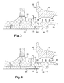
figure 5 est une vue schématique en coupe axiale d'une extrémité de la bague interne d'un palier de guidage et d'un jonc annulaire monté dans une gorge de la portée cylindrique selon une variante de l'invention ; - les
figures 6 à 8 représentent les phases successives d'expansion radiale du jonc annulaire de lafigure 5 , conduisant au blocage et au serrage de l'anneau sur la bague interne du palier de guidage.
- the
figure 1 is a schematic half-view in axial section of a high pressure compressor shaft guide bearing according to the prior art; - the
figure 2 is a schematic view on a larger scale of the area delimited in dotted lines on thefigure 1 ; - the
figure 3 is a schematic view in axial section of an end of an inner ring of a guide bearing and an annular ring mounted in an annular groove of the cylindrical bearing surface according to one embodiment of the invention; - the
figure 4 is a view identical to thefigure 3 wherein the ring is in the axial locking position of the inner ring; - the
figure 5 is a schematic view in axial section of an end of the inner ring of a guide bearing and an annular ring mounted in a groove of the cylindrical seat according to a variant of the invention; - the
Figures 6 to 8 represent the successive phases of radial expansion of the annular ring of thefigure 5 , leading to the locking and tightening of the ring on the inner ring of the guide bearing.
On se réfère tout d'abord aux
Un pignon connique 27 est monté sur l'extrémité amont de l'arbre 16 du compresseur haute pression 10 et comprend en aval une portée cylindrique 26 intercalée entre l'arbre 16 et la bague interne 20 du palier de guidage 18. Le pignon 27 comprend à son extrémité amont une denture tronconique 28 engrenant avec un pignon conique de l'extrémité interne d'un arbre radial disposé dans un bras de passage (non représenté) du carter intermédiaire 12. Le pignon conique 27 permet de transmettre une partie du couple de rotation de l'arbre 16 du compresseur haute pression 10 à l'arbre radial pour faire fonctionner des équipements situés à la périphérie externe de la turbomachine.A
La bague interne 20 du palier 18 est bloquée axialement à l'amont sur une cale annulaire 30 appliquée contre un rebord annulaire radial 32 de l'extrémité amont de la portée cylindrique 26 du pignon conique 27 et à l'aval par un anneau 34 vissé sur un filetage externe 35 de la portée cylindrique 26. L'ensemble constitué du palier 18, des pignons coniques, de la cale 30 et de l'anneau 34 est un ensemble modulaire qui est fourni pré-assemblé avant son montage dans la turbomachine. L'usinage de la cale annulaire 30, avant assemblage de l'ensemble modulaire, permet d'assurer lors du montage de l'ensemble modulaire dans la turbomachine, un positionnement axial optimal du pignon conique 27 de manière à ce qu'il engrène parfaitement avec le pignon conique de l'arbre radial.The
L'anneau 34 comprend (
Les extrémités aval des parois cylindriques amont 36 et aval 38 comprennent chacune un joint à labyrinthe 44 coopérant avec des pistes d'abradables 46 portées par une paroi annulaire 48 fixée par boulonnage sur la face aval de la bride 24 du carter intermédiaire 12. Une paroi tronconique 50 à section se réduisant vers l'amont est fixée par boulonnage à sa périphérie externe sur la face amont de la bride 24 du carter intermédiaire 12 et porte à sa périphérie interne des pistes d'abradables 52 coopérant avec un joint à labyrinthe 54 solidaire en rotation de l'arbre 16 du compresseur haute pression 10. Les parois 48 et 50 permettent ainsi d'assurer l'étanchéité de l'enceinte contenant le palier de guidage 18 en évitant que l'huile de lubrification du palier 18 qui est en suspension ne s'échappe de l'enceinte.The downstream ends of the upstream
Ce type de maintien axial de la bague interne 20 du palier de guidage 18 par vissage de l'anneau 34 sur la portée cylindrique 26 n'est pas satisfaisant pour les raisons indiquées ci-dessus.This type of axial retention of the
Selon l'invention, les filetages de la portée cylindrique 26 et de l'anneau 34 sont remplacés par deux gorges annulaires en regard l'une de l'autre, l'une 56 étant formée dans la portée cylindrique 26 et l'autre 60 étant formée dans la surface interne de l'anneau 34 (
Le jonc annulaire 64 est réalisé dans un matériau à mémoire de forme susceptible de présenter un effet mémoire de forme simple. A cette fin, le jonc 64 est préalablement soumis à une phase d'éducation dans laquelle il est dans un premier temps conformé dans une position expansée de sorte que sa périphérie externe soit située à l'extérieur de la gorge 56 de la portée cylindrique 26, à une température supérieure à la température de transition du matériau à mémoire de forme de sorte que ce dernier se trouve en phase austénitique.The
Puis, dans un second temps, le jonc 64 est resserré sur lui-même mécaniquement afin que sa périphérie externe soit située dans la gorge 56 de la portée cylindrique 26, à une température inférieure à la température de transition précitée de sorte que le matériau à mémoire de forme se trouve alors en phase martensitique. A cette fin, la profondeur de la gorge annulaire 56 de la portée cylindrique 26 est au moins égale à l'épaisseur radiale du jonc 64.Then, in a second step, the
Le jonc 64 est alors prêt à subir une expansion radiale lorsque la température augmente jusqu'à la température de transition du matériau à mémoire de forme.The
Du fait du caractère irréversible de l'effet mémoire de forme simple, le jonc 64 conserve sa forme expansée quelle que soit l'évolution ultérieure de la température.Due to the irreversible nature of the simple shape memory effect, the
Dans le premier mode de réalisation de l'invention représenté aux
La profondeur de la gorge annulaire 60 de l'anneau 34 est quant à elle inférieure au diamètre de la section du jonc 64 et est de l'ordre de la moitié de ce diamètre. A l'état expansé, le jonc 64 est ainsi partiellement à l'intérieur de la gorge 60 de l'anneau 34 et partiellement à l'intérieur de la gorge 56 de la portée cylindrique 26 (
Il est préférable que le diamètre externe du jonc 64 à l'état expansé soit légèrement supérieur au diamètre du fond de la gorge 60 de l'anneau 34 afin que toute la périphérie externe du jonc 64 vienne en contact avec le fond de la gorge 60 de l'anneau 34, afin de bloquer le jonc annulaire 64 dans le fond de la gorge 60 de l'anneau 34.It is preferable that the outer diameter of the
Le blocage axial de la bague interne 20 sur la portée cylindrique 26 s'effectue de la manière suivante : le jonc annulaire 64 est monté dans la gorge 60 de la portée cylindrique 26 à une température inférieure à la température de transition du matériau à mémoire de forme de sorte que le jonc 64 qui est en phase martensitique est souple. L'anneau 34 est ensuite monté coulissant sur la portée cylindrique 26 pour que son extrémité amont vienne en contact avec l'extrémité aval de la bague interne 20 et de manière à ce que sa gorge annulaire 60 viennent en regard avec la gorge annulaire 56 de la portée cylindrique 26. L'augmentation de la température au-dessus de la température de transition induit un passage du jonc 64 en phase austénitique conduisant à une augmentation de sa rigidité et à son expansion radiale à l'intérieur de la gorge 60 de l'anneau 34, pour le blocage de l'anneau 34 sur la portée cylindrique 26.The axial locking of the
Le démontage est réalisé en refroidissant la bague interne 20 qui par conduction refroidit le jonc 64 et le fait passer de son état rigide en phase austénitique à son état souple en phase martensitique, le jonc 64 restant à l'état expansé. Une traction vers l'aval exercée sur l'anneau 34 permet de contracter radialement le jonc 64 dans la gorge 56 de la portée cylindrique 26 et autorise un démontage de l'anneau 34 et de la bague interne 20.Disassembly is achieved by cooling the
Dans le second mode de réalisation de l'invention, représenté aux
Dans cette variante, le jonc 66 exerce à la fois la fonction de blocage de l'anneau 34 sur la portée cylindrique 26 et une fonction de serrage de l'anneau 34 sur l'extrémité aval de la bague interne 20. En effet, lorsque la température augmente et passe au dessus de la température de transition du matériau à mémoire de forme, le jonc 66 s'expanse radialement et son chanfrein 68 vient en contact avec la paroi oblique 70 de la gorge 62 de l'anneau 34 (
Le serrage est rendu possible par le fait que le jonc 66 exerce une force suffisante sur l'anneau 34 en direction de la bague interne 20. Cette force est par exemple de l'ordre de cinq fois supérieure à la force nécessaire à la déformation du jonc 66 lors de la phase d'apprentissage.Tightening is made possible by the fact that the
La gorge 62 de l'anneau 34 a une longueur axiale légèrement supérieure à celle de la gorge 58 de la portée cylindrique 26.The
Lors de l'étape de démontage, l'intégration d'un chanfrein 68 sur le jonc annulaire 66 coopérant avec une paroi oblique 70 de la gorge 62 de l'anneau 34 facilite la contraction du jonc annulaire 66 dans la gorge 58 de la portée cylindrique 26 comparativement à un jonc annulaire 64 sans chanfrein.During the disassembly step, the integration of a
L'invention ainsi décrite évite tout risque d'endommagement des joints à labyrinthe 44 portés par l'anneau 34 et assure une étanchéité optimale de l'enceinte contenant le palier de guidage 18. Le montage coulissant de l'anneau 34 permet un centrage simple et efficace de celui-ci sur la portée cylindrique 26. La température de transition du matériau à mémoire de forme est choisie pour correspondre approximativement à une température ambiante dans les ateliers de montage de turbomachine, ce qui permet que le jonc reste en phase austénitique et ainsi conserve une bonne rigidité assurant un blocage efficace de l'anneau 34 sur la portée cylindrique 26.The invention thus described avoids any risk of damage to the labyrinth seals 44 carried by the
La température de transition du matériau à mémoire de forme peut être inférieure à 20°C et est avantageusement de l'ordre de 15°C.The transition temperature of the shape memory material may be less than 20 ° C and is preferably of the order of 15 ° C.
Le jonc annulaire 64, 66 est fendu, afin de faciliter son insertion dans la gorge de la portée cylindrique 26 sous sa forme contractée.The
Il est également possible d'utiliser un jonc annulaire 64, 66 présentant un effet mémoire de forme double, c'est-à-dire capable de s'expanser lorsque la température augmente au-delà de la température de transition de son matériau et également capable de se contracter lorsque la température diminue en dessous de cette même température de transition. Cependant, l'effet mémoire de forme simple permet un plus grand nombre de cycles de déformation entre l'état initial et l'état expansé qu'avec un jonc annulaire à effet mémoire de forme double, ce qui permet d'augmenter la durée de vie d'un jonc annulaire.It is also possible to use an
Dans la description ci-dessus, le terme « portée cylindrique » a été utilisé pour désigner une portée cylindrique fixée à l'arbre de rotation du compresseur haute pression. L'invention s'applique bien entendu au cas où la portée cylindrique fait partie intégrante de l'arbre de rotation.In the above description, the term "cylindrical scope" has been used to designate a cylindrical scope attached to the rotation shaft of the high pressure compressor. The invention applies of course in case the cylindrical seat is an integral part of the rotation shaft.
Claims (13)
Applications Claiming Priority (1)
| Application Number | Priority Date | Filing Date | Title |
|---|---|---|---|
| FR0802924A FR2931874B1 (en) | 2008-05-29 | 2008-05-29 | AXIAL BLOCKING DEVICE FOR TREE GUIDE BEARING IN TURBOMACHINE. |
Publications (2)
| Publication Number | Publication Date |
|---|---|
| EP2128390A1 true EP2128390A1 (en) | 2009-12-02 |
| EP2128390B1 EP2128390B1 (en) | 2017-07-05 |
Family
ID=40342789
Family Applications (1)
| Application Number | Title | Priority Date | Filing Date |
|---|---|---|---|
| EP09160424.9A Active EP2128390B1 (en) | 2008-05-29 | 2009-05-15 | Locking device of a bearing on a shaft in a turbomachine |
Country Status (3)
| Country | Link |
|---|---|
| US (1) | US8246255B2 (en) |
| EP (1) | EP2128390B1 (en) |
| FR (1) | FR2931874B1 (en) |
Cited By (1)
| Publication number | Priority date | Publication date | Assignee | Title |
|---|---|---|---|---|
| US20140144121A1 (en) * | 2012-11-28 | 2014-05-29 | Pratt & Whitney Canada Corp. | Gas turbine engine with bearing oil leak recuperation system |
Families Citing this family (20)
| Publication number | Priority date | Publication date | Assignee | Title |
|---|---|---|---|---|
| US8925463B1 (en) * | 2009-09-03 | 2015-01-06 | Kms Consulting, Llc | Pressure relief system for gun fired cannon cartridges |
| US8684696B2 (en) | 2009-12-31 | 2014-04-01 | Rolls-Royce North American Technologies, Inc. | Gas turbine engine and main engine rotor assembly and disassembly |
| FR2963062B1 (en) * | 2010-07-20 | 2012-08-31 | Snecma | ASSEMBLY BETWEEN A COMPRESSOR SHAFT SWITCH AND A TAPERED SPROCKET FOR DRIVING A TURBOMACHINE ACCESSORIES HOUSING |
| FR2975149B1 (en) * | 2011-05-09 | 2013-06-07 | Snecma | SYSTEM FOR ATTACHING TWO TUBULAR PIECES, ONE IN ANOTHER BEARING A BEARING BEARING |
| FR2976316B1 (en) * | 2011-06-08 | 2013-06-14 | Snecma | TURBOMACHINE COMPRISING A FLOATING BEARING FOR GUIDING A TURBOMACHINE TREE |
| JP5872341B2 (en) * | 2012-03-21 | 2016-03-01 | 日立オートモティブシステムズ九州株式会社 | Propeller shaft and constant velocity joint used for this propeller shaft |
| US9617916B2 (en) | 2012-11-28 | 2017-04-11 | Pratt & Whitney Canada Corp. | Gas turbine engine with bearing buffer air flow and method |
| WO2014154289A1 (en) * | 2013-03-28 | 2014-10-02 | Aktiebolaget Skf | Bearing assembly and method for assembling and mounting said bearing assembly with a component supporting said bearing assembly |
| WO2014154287A1 (en) * | 2013-03-28 | 2014-10-02 | Aktiebolaget Skf | Bearing assembly and method for assembling and mounting said bearing assembly with a component supporting said bearing assembly |
| US10274017B2 (en) | 2016-10-21 | 2019-04-30 | General Electric Company | Method and system for elastic bearing support |
| US11105204B2 (en) | 2019-06-11 | 2021-08-31 | Pratt & Whitney Canada Corp. | Turbine assembly |
| US11420755B2 (en) | 2019-08-08 | 2022-08-23 | General Electric Company | Shape memory alloy isolator for a gas turbine engine |
| US11105223B2 (en) | 2019-08-08 | 2021-08-31 | General Electric Company | Shape memory alloy reinforced casing |
| US11280219B2 (en) | 2019-11-27 | 2022-03-22 | General Electric Company | Rotor support structures for rotating drum rotors of gas turbine engines |
| US11274557B2 (en) | 2019-11-27 | 2022-03-15 | General Electric Company | Damper assemblies for rotating drum rotors of gas turbine engines |
| US11313280B2 (en) * | 2020-07-16 | 2022-04-26 | Raytheon Technologies Corporation | Gas turbine engine including seal assembly with abradable coating and cutter |
| US11293351B2 (en) * | 2020-07-16 | 2022-04-05 | Raytheon Technologies Corporation | Gas turbine engine including seal assembly with abradable coating including magnetic particles embedded in polymer |
| US11313281B2 (en) * | 2020-07-16 | 2022-04-26 | Raytheon Technologies Corporation | Gas turbine engine including seal assembly with abradable coating including magnetic particles |
| US11828235B2 (en) | 2020-12-08 | 2023-11-28 | General Electric Company | Gearbox for a gas turbine engine utilizing shape memory alloy dampers |
| US11542819B2 (en) * | 2021-02-17 | 2023-01-03 | Pratt & Whitney Canada Corp. | Split ring seal for gas turbine engine rotor |
Citations (6)
| Publication number | Priority date | Publication date | Assignee | Title |
|---|---|---|---|---|
| FR2734874A1 (en) | 1995-05-31 | 1996-12-06 | Snecma | Attachment of bearing on shaft |
| US5685650A (en) | 1996-01-16 | 1997-11-11 | Allen-Bradley Company, Inc. | Bearing assembly utilizing improved clamping arrangement |
| EP0987457A1 (en) * | 1998-09-17 | 2000-03-22 | Societe Nationale D'etude Et De Construction De Moteurs D'aviation "Snecma" | Bearing retaining device in particular for a high pressure compressor shaft |
| EP1498624A1 (en) * | 2003-07-15 | 2005-01-19 | Snecma Moteurs | Device for fixing a motor shaft onto a bearing support |
| EP1712806A2 (en) | 2005-04-15 | 2006-10-18 | Snecma | Assembly arrangement between an inner bearing ring and a trunnion, bearing ring and trunnion adapted to the arrangement, and a turbo machine equipped with them |
| EP1813792A1 (en) | 2006-01-30 | 2007-08-01 | Snecma | Engine shaft linking system with retractable nut |
Family Cites Families (21)
| Publication number | Priority date | Publication date | Assignee | Title |
|---|---|---|---|---|
| GB1092516A (en) * | 1965-09-29 | 1967-11-29 | Rolls Royce | Apparatus for locking two members |
| US3750489A (en) * | 1972-06-07 | 1973-08-07 | Caterpillar Tractor Co | Composite drive assembly |
| JPS63290139A (en) * | 1987-05-21 | 1988-11-28 | Shicoh Eng Co Ltd | Motor rotor-fastening structure |
| US4836750A (en) * | 1988-06-15 | 1989-06-06 | Pratt & Whitney Canada Inc. | Rotor assembly |
| US5226683A (en) * | 1990-11-16 | 1993-07-13 | Julien Gerald J | Reusable metallic seal using memory metal |
| JPH052703A (en) * | 1991-06-26 | 1993-01-08 | Matsushita Electric Ind Co Ltd | Rotary head cylinder device |
| US5320488A (en) * | 1993-01-21 | 1994-06-14 | General Electric Company | Turbine disk interstage seal anti-rotation system |
| US5863137A (en) * | 1997-02-07 | 1999-01-26 | Emerson Power Transmission Corp. | Shaft locking device for bearing assemblies |
| US6780114B2 (en) * | 1999-12-15 | 2004-08-24 | Ntn Corporation | Drive wheel bearing assembly |
| SE519561C2 (en) * | 2000-07-03 | 2003-03-11 | Bofors Carl Gustaf Ab | Device for rocket engines to prevent rocket engine from exploding in case of external fire |
| JP3956619B2 (en) * | 2000-07-31 | 2007-08-08 | 日本精工株式会社 | Wheel drive unit and its assembly method |
| JP4193344B2 (en) * | 2000-08-22 | 2008-12-10 | 日本精工株式会社 | Wheel drive unit |
| US20050244245A1 (en) * | 2004-04-30 | 2005-11-03 | Anatoly Efremov | Method and devices to limit a creep of mechanical fasteners |
| US7147436B2 (en) * | 2004-04-15 | 2006-12-12 | United Technologies Corporation | Turbine engine rotor retainer |
| US7121632B2 (en) * | 2004-05-05 | 2006-10-17 | Gkn Driveline North Amercia, Inc. | Shaft and wheel hub retention assembly |
| FR2873161B1 (en) * | 2004-07-15 | 2008-10-10 | Snecma Moteurs Sa | ASSEMBLY COMPRISING A ROTARY SHAFT AND A BEARING BEARING |
| US7452188B2 (en) * | 2005-09-26 | 2008-11-18 | Pratt & Whitney Canada Corp. | Pre-stretched tie-bolt for use in a gas turbine engine and method |
| FR2917783B1 (en) * | 2007-06-25 | 2013-04-12 | Snecma | ENGINE SHAFT CONNECTION SYSTEM WITH SELF-EXTRACTOR NUT |
| US7942635B1 (en) * | 2007-08-02 | 2011-05-17 | Florida Turbine Technologies, Inc. | Twin spool rotor assembly for a small gas turbine engine |
| US8419350B2 (en) * | 2008-09-08 | 2013-04-16 | Bosch Mahle Turbo Systems Gmbh & Co. Kg | Exhaust-gas turbocharger for an internal combustion engine |
| WO2010112509A2 (en) * | 2009-04-01 | 2010-10-07 | Siemens Aktiengesellschaft | Rotor for a turbomachine |
-
2008
- 2008-05-29 FR FR0802924A patent/FR2931874B1/en active Active
-
2009
- 2009-05-15 EP EP09160424.9A patent/EP2128390B1/en active Active
- 2009-05-26 US US12/471,747 patent/US8246255B2/en active Active
Patent Citations (6)
| Publication number | Priority date | Publication date | Assignee | Title |
|---|---|---|---|---|
| FR2734874A1 (en) | 1995-05-31 | 1996-12-06 | Snecma | Attachment of bearing on shaft |
| US5685650A (en) | 1996-01-16 | 1997-11-11 | Allen-Bradley Company, Inc. | Bearing assembly utilizing improved clamping arrangement |
| EP0987457A1 (en) * | 1998-09-17 | 2000-03-22 | Societe Nationale D'etude Et De Construction De Moteurs D'aviation "Snecma" | Bearing retaining device in particular for a high pressure compressor shaft |
| EP1498624A1 (en) * | 2003-07-15 | 2005-01-19 | Snecma Moteurs | Device for fixing a motor shaft onto a bearing support |
| EP1712806A2 (en) | 2005-04-15 | 2006-10-18 | Snecma | Assembly arrangement between an inner bearing ring and a trunnion, bearing ring and trunnion adapted to the arrangement, and a turbo machine equipped with them |
| EP1813792A1 (en) | 2006-01-30 | 2007-08-01 | Snecma | Engine shaft linking system with retractable nut |
Cited By (1)
| Publication number | Priority date | Publication date | Assignee | Title |
|---|---|---|---|---|
| US20140144121A1 (en) * | 2012-11-28 | 2014-05-29 | Pratt & Whitney Canada Corp. | Gas turbine engine with bearing oil leak recuperation system |
Also Published As
| Publication number | Publication date |
|---|---|
| US8246255B2 (en) | 2012-08-21 |
| US20090297083A1 (en) | 2009-12-03 |
| FR2931874B1 (en) | 2010-06-25 |
| EP2128390B1 (en) | 2017-07-05 |
| FR2931874A1 (en) | 2009-12-04 |
Similar Documents
| Publication | Publication Date | Title |
|---|---|---|
| EP2128390B1 (en) | Locking device of a bearing on a shaft in a turbomachine | |
| EP2085574B1 (en) | Centring of a part inside a shaft | |
| EP1605139B1 (en) | Turbomachine with axial retention means for the rotor | |
| EP3074611B1 (en) | Device for centring and guiding the rotation of a turbine engine shaft including improved means for retaining the external bearing ring | |
| EP3728817B1 (en) | Geared turbofan engine | |
| EP3256698B1 (en) | Retainer nut for axial blockage of a bearing in a turbomachine | |
| EP2096270B1 (en) | Split annular trim strip for rotating part of turbomachine | |
| FR3017163A1 (en) | DEVICE FOR A NON-CAREED PROPELLER HAVING A VARIABLE SHIFT OF A TURBOMACHINE | |
| EP3759319B1 (en) | Assembly for a turbomachine | |
| EP2071141B1 (en) | Watertigh fixing of a bearing support in a turbomachine | |
| FR2971022A1 (en) | COMPRESSOR RECTIFIER STAGE FOR A TURBOMACHINE | |
| FR2633023A1 (en) | Device and method for coupling a turbine shaft to a journal | |
| EP2071130B1 (en) | Installation of tubes for pressurising an internal enclosure in a turbomachine | |
| FR2978793A1 (en) | Turbine rotor for e.g. turbojet engine of aircraft, has annular ring deformed or moved in order to compensate deformation/displacement of plate so as to ensure sealing of annular space irrespective of position of plate | |
| EP4090833B1 (en) | Assembly for a turbine engine | |
| FR2949138A1 (en) | Turbomachine e.g. turbopropeller, for airplane, has snap ring cooperating with anti-rotation collar by axial abutment, where collar has grooves co-operating with complementary grooves of nut and ring to immobilize rotation of collar | |
| FR2944557A1 (en) | Turbomachine e.g. turbopropeller engine, for airplane, has blocking unit carried by ring and cooperated along circumferential direction with cylindrical sleeve and journal, where cylindrical sleeve encloses low pressure turbine shaft | |
| EP3850233B1 (en) | System for the axial retention of a ring of a rolling element bearing | |
| FR2981124A1 (en) | Turboshaft engine e.g. turbojet, for aircraft, has cylindrical sleeve whose downstream ends include axial support units on which pivot is supported due to differential thermal dilations in direction opposed to upstream ends of sleeve | |
| WO2023002121A1 (en) | Sleeve mounted onto a low-pressure shaft in a turbomachine | |
| WO2021058882A1 (en) | Aircraft turbine engine | |
| FR3116305A1 (en) | CONNECTING SHAFT OF A HIGH PRESSURE BODY OF A TURBOMACHINE | |
| FR3095242A1 (en) | TURBOMACHINE MODULE EQUIPPED WITH A DAMPING DEVICE FOR TURBOMACHINE GUIDE BEARING | |
| FR2979679A1 (en) | Separating cage for rolling bearing mounted between coaxial driving shafts of high pressure and low pressure turbines, of e.g. turbojet, of aircraft, has guards whose external walls are located inside relative to external walls of rails | |
| EP3377791A1 (en) | Valve for the circulation of a fluid, comprising a valve body |
Legal Events
| Date | Code | Title | Description |
|---|---|---|---|
| PUAI | Public reference made under article 153(3) epc to a published international application that has entered the european phase |
Free format text: ORIGINAL CODE: 0009012 |
|
| AK | Designated contracting states |
Kind code of ref document: A1 Designated state(s): AT BE BG CH CY CZ DE DK EE ES FI FR GB GR HR HU IE IS IT LI LT LU LV MC MK MT NL NO PL PT RO SE SI SK TR |
|
| 17P | Request for examination filed |
Effective date: 20100406 |
|
| REG | Reference to a national code |
Ref country code: DE Ref legal event code: R079 Ref document number: 602009046939 Country of ref document: DE Free format text: PREVIOUS MAIN CLASS: F01D0025160000 Ipc: F02C0007060000 |
|
| GRAP | Despatch of communication of intention to grant a patent |
Free format text: ORIGINAL CODE: EPIDOSNIGR1 |
|
| RIC1 | Information provided on ipc code assigned before grant |
Ipc: F16C 35/073 20060101ALI20170214BHEP Ipc: F01D 25/16 20060101ALI20170214BHEP Ipc: F02C 7/06 20060101AFI20170214BHEP |
|
| INTG | Intention to grant announced |
Effective date: 20170301 |
|
| GRAS | Grant fee paid |
Free format text: ORIGINAL CODE: EPIDOSNIGR3 |
|
| GRAA | (expected) grant |
Free format text: ORIGINAL CODE: 0009210 |
|
| AK | Designated contracting states |
Kind code of ref document: B1 Designated state(s): AT BE BG CH CY CZ DE DK EE ES FI FR GB GR HR HU IE IS IT LI LT LU LV MC MK MT NL NO PL PT RO SE SI SK TR |
|
| REG | Reference to a national code |
Ref country code: GB Ref legal event code: FG4D Free format text: NOT ENGLISH |
|
| REG | Reference to a national code |
Ref country code: CH Ref legal event code: EP |
|
| REG | Reference to a national code |
Ref country code: AT Ref legal event code: REF Ref document number: 906781 Country of ref document: AT Kind code of ref document: T Effective date: 20170715 |
|
| REG | Reference to a national code |
Ref country code: IE Ref legal event code: FG4D Free format text: LANGUAGE OF EP DOCUMENT: FRENCH |
|
| REG | Reference to a national code |
Ref country code: DE Ref legal event code: R096 Ref document number: 602009046939 Country of ref document: DE |
|
| REG | Reference to a national code |
Ref country code: NL Ref legal event code: MP Effective date: 20170705 |
|
| REG | Reference to a national code |
Ref country code: AT Ref legal event code: MK05 Ref document number: 906781 Country of ref document: AT Kind code of ref document: T Effective date: 20170705 |
|
| REG | Reference to a national code |
Ref country code: LT Ref legal event code: MG4D |
|
| PG25 | Lapsed in a contracting state [announced via postgrant information from national office to epo] |
Ref country code: LT Free format text: LAPSE BECAUSE OF FAILURE TO SUBMIT A TRANSLATION OF THE DESCRIPTION OR TO PAY THE FEE WITHIN THE PRESCRIBED TIME-LIMIT Effective date: 20170705 Ref country code: FI Free format text: LAPSE BECAUSE OF FAILURE TO SUBMIT A TRANSLATION OF THE DESCRIPTION OR TO PAY THE FEE WITHIN THE PRESCRIBED TIME-LIMIT Effective date: 20170705 Ref country code: NO Free format text: LAPSE BECAUSE OF FAILURE TO SUBMIT A TRANSLATION OF THE DESCRIPTION OR TO PAY THE FEE WITHIN THE PRESCRIBED TIME-LIMIT Effective date: 20171005 Ref country code: AT Free format text: LAPSE BECAUSE OF FAILURE TO SUBMIT A TRANSLATION OF THE DESCRIPTION OR TO PAY THE FEE WITHIN THE PRESCRIBED TIME-LIMIT Effective date: 20170705 Ref country code: SE Free format text: LAPSE BECAUSE OF FAILURE TO SUBMIT A TRANSLATION OF THE DESCRIPTION OR TO PAY THE FEE WITHIN THE PRESCRIBED TIME-LIMIT Effective date: 20170705 Ref country code: NL Free format text: LAPSE BECAUSE OF FAILURE TO SUBMIT A TRANSLATION OF THE DESCRIPTION OR TO PAY THE FEE WITHIN THE PRESCRIBED TIME-LIMIT Effective date: 20170705 Ref country code: HR Free format text: LAPSE BECAUSE OF FAILURE TO SUBMIT A TRANSLATION OF THE DESCRIPTION OR TO PAY THE FEE WITHIN THE PRESCRIBED TIME-LIMIT Effective date: 20170705 |
|
| PG25 | Lapsed in a contracting state [announced via postgrant information from national office to epo] |
Ref country code: LV Free format text: LAPSE BECAUSE OF FAILURE TO SUBMIT A TRANSLATION OF THE DESCRIPTION OR TO PAY THE FEE WITHIN THE PRESCRIBED TIME-LIMIT Effective date: 20170705 Ref country code: BG Free format text: LAPSE BECAUSE OF FAILURE TO SUBMIT A TRANSLATION OF THE DESCRIPTION OR TO PAY THE FEE WITHIN THE PRESCRIBED TIME-LIMIT Effective date: 20171005 Ref country code: IS Free format text: LAPSE BECAUSE OF FAILURE TO SUBMIT A TRANSLATION OF THE DESCRIPTION OR TO PAY THE FEE WITHIN THE PRESCRIBED TIME-LIMIT Effective date: 20171105 Ref country code: PL Free format text: LAPSE BECAUSE OF FAILURE TO SUBMIT A TRANSLATION OF THE DESCRIPTION OR TO PAY THE FEE WITHIN THE PRESCRIBED TIME-LIMIT Effective date: 20170705 Ref country code: ES Free format text: LAPSE BECAUSE OF FAILURE TO SUBMIT A TRANSLATION OF THE DESCRIPTION OR TO PAY THE FEE WITHIN THE PRESCRIBED TIME-LIMIT Effective date: 20170705 Ref country code: GR Free format text: LAPSE BECAUSE OF FAILURE TO SUBMIT A TRANSLATION OF THE DESCRIPTION OR TO PAY THE FEE WITHIN THE PRESCRIBED TIME-LIMIT Effective date: 20171006 |
|
| REG | Reference to a national code |
Ref country code: DE Ref legal event code: R097 Ref document number: 602009046939 Country of ref document: DE |
|
| REG | Reference to a national code |
Ref country code: FR Ref legal event code: PLFP Year of fee payment: 10 |
|
| PG25 | Lapsed in a contracting state [announced via postgrant information from national office to epo] |
Ref country code: DK Free format text: LAPSE BECAUSE OF FAILURE TO SUBMIT A TRANSLATION OF THE DESCRIPTION OR TO PAY THE FEE WITHIN THE PRESCRIBED TIME-LIMIT Effective date: 20170705 Ref country code: CZ Free format text: LAPSE BECAUSE OF FAILURE TO SUBMIT A TRANSLATION OF THE DESCRIPTION OR TO PAY THE FEE WITHIN THE PRESCRIBED TIME-LIMIT Effective date: 20170705 Ref country code: RO Free format text: LAPSE BECAUSE OF FAILURE TO SUBMIT A TRANSLATION OF THE DESCRIPTION OR TO PAY THE FEE WITHIN THE PRESCRIBED TIME-LIMIT Effective date: 20170705 |
|
| PLBE | No opposition filed within time limit |
Free format text: ORIGINAL CODE: 0009261 |
|
| STAA | Information on the status of an ep patent application or granted ep patent |
Free format text: STATUS: NO OPPOSITION FILED WITHIN TIME LIMIT |
|
| PG25 | Lapsed in a contracting state [announced via postgrant information from national office to epo] |
Ref country code: IT Free format text: LAPSE BECAUSE OF FAILURE TO SUBMIT A TRANSLATION OF THE DESCRIPTION OR TO PAY THE FEE WITHIN THE PRESCRIBED TIME-LIMIT Effective date: 20170705 Ref country code: SK Free format text: LAPSE BECAUSE OF FAILURE TO SUBMIT A TRANSLATION OF THE DESCRIPTION OR TO PAY THE FEE WITHIN THE PRESCRIBED TIME-LIMIT Effective date: 20170705 Ref country code: EE Free format text: LAPSE BECAUSE OF FAILURE TO SUBMIT A TRANSLATION OF THE DESCRIPTION OR TO PAY THE FEE WITHIN THE PRESCRIBED TIME-LIMIT Effective date: 20170705 |
|
| 26N | No opposition filed |
Effective date: 20180406 |
|
| PG25 | Lapsed in a contracting state [announced via postgrant information from national office to epo] |
Ref country code: SI Free format text: LAPSE BECAUSE OF FAILURE TO SUBMIT A TRANSLATION OF THE DESCRIPTION OR TO PAY THE FEE WITHIN THE PRESCRIBED TIME-LIMIT Effective date: 20170705 |
|
| PG25 | Lapsed in a contracting state [announced via postgrant information from national office to epo] |
Ref country code: MT Free format text: LAPSE BECAUSE OF FAILURE TO SUBMIT A TRANSLATION OF THE DESCRIPTION OR TO PAY THE FEE WITHIN THE PRESCRIBED TIME-LIMIT Effective date: 20170705 |
|
| REG | Reference to a national code |
Ref country code: CH Ref legal event code: PL |
|
| REG | Reference to a national code |
Ref country code: BE Ref legal event code: MM Effective date: 20180531 |
|
| PG25 | Lapsed in a contracting state [announced via postgrant information from national office to epo] |
Ref country code: MC Free format text: LAPSE BECAUSE OF FAILURE TO SUBMIT A TRANSLATION OF THE DESCRIPTION OR TO PAY THE FEE WITHIN THE PRESCRIBED TIME-LIMIT Effective date: 20170705 |
|
| REG | Reference to a national code |
Ref country code: IE Ref legal event code: MM4A |
|
| PG25 | Lapsed in a contracting state [announced via postgrant information from national office to epo] |
Ref country code: CH Free format text: LAPSE BECAUSE OF NON-PAYMENT OF DUE FEES Effective date: 20180531 Ref country code: LI Free format text: LAPSE BECAUSE OF NON-PAYMENT OF DUE FEES Effective date: 20180531 |
|
| PG25 | Lapsed in a contracting state [announced via postgrant information from national office to epo] |
Ref country code: LU Free format text: LAPSE BECAUSE OF NON-PAYMENT OF DUE FEES Effective date: 20180515 |
|
| PG25 | Lapsed in a contracting state [announced via postgrant information from national office to epo] |
Ref country code: IE Free format text: LAPSE BECAUSE OF NON-PAYMENT OF DUE FEES Effective date: 20180515 |
|
| PG25 | Lapsed in a contracting state [announced via postgrant information from national office to epo] |
Ref country code: BE Free format text: LAPSE BECAUSE OF NON-PAYMENT OF DUE FEES Effective date: 20180531 |
|
| PG25 | Lapsed in a contracting state [announced via postgrant information from national office to epo] |
Ref country code: TR Free format text: LAPSE BECAUSE OF FAILURE TO SUBMIT A TRANSLATION OF THE DESCRIPTION OR TO PAY THE FEE WITHIN THE PRESCRIBED TIME-LIMIT Effective date: 20170705 |
|
| PG25 | Lapsed in a contracting state [announced via postgrant information from national office to epo] |
Ref country code: PT Free format text: LAPSE BECAUSE OF FAILURE TO SUBMIT A TRANSLATION OF THE DESCRIPTION OR TO PAY THE FEE WITHIN THE PRESCRIBED TIME-LIMIT Effective date: 20170705 Ref country code: HU Free format text: LAPSE BECAUSE OF FAILURE TO SUBMIT A TRANSLATION OF THE DESCRIPTION OR TO PAY THE FEE WITHIN THE PRESCRIBED TIME-LIMIT; INVALID AB INITIO Effective date: 20090515 |
|
| PG25 | Lapsed in a contracting state [announced via postgrant information from national office to epo] |
Ref country code: CY Free format text: LAPSE BECAUSE OF FAILURE TO SUBMIT A TRANSLATION OF THE DESCRIPTION OR TO PAY THE FEE WITHIN THE PRESCRIBED TIME-LIMIT Effective date: 20170705 Ref country code: MK Free format text: LAPSE BECAUSE OF NON-PAYMENT OF DUE FEES Effective date: 20170705 |
|
| PGFP | Annual fee paid to national office [announced via postgrant information from national office to epo] |
Ref country code: FR Payment date: 20230420 Year of fee payment: 15 Ref country code: DE Payment date: 20230419 Year of fee payment: 15 |
|
| PGFP | Annual fee paid to national office [announced via postgrant information from national office to epo] |
Ref country code: GB Payment date: 20230420 Year of fee payment: 15 |