EP2127999A2 - System for assisting a driver while manoeuvring a truck towards a loading or unloading bay - Google Patents
System for assisting a driver while manoeuvring a truck towards a loading or unloading bay Download PDFInfo
- Publication number
- EP2127999A2 EP2127999A2 EP09156547A EP09156547A EP2127999A2 EP 2127999 A2 EP2127999 A2 EP 2127999A2 EP 09156547 A EP09156547 A EP 09156547A EP 09156547 A EP09156547 A EP 09156547A EP 2127999 A2 EP2127999 A2 EP 2127999A2
- Authority
- EP
- European Patent Office
- Prior art keywords
- truck
- distance
- tail end
- bay
- edge
- Prior art date
- Legal status (The legal status is an assumption and is not a legal conclusion. Google has not performed a legal analysis and makes no representation as to the accuracy of the status listed.)
- Withdrawn
Links
Images

Classifications
-
- B—PERFORMING OPERATIONS; TRANSPORTING
- B62—LAND VEHICLES FOR TRAVELLING OTHERWISE THAN ON RAILS
- B62D—MOTOR VEHICLES; TRAILERS
- B62D13/00—Steering specially adapted for trailers
- B62D13/06—Steering specially adapted for trailers for backing a normally drawn trailer
-
- B—PERFORMING OPERATIONS; TRANSPORTING
- B60—VEHICLES IN GENERAL
- B60Q—ARRANGEMENT OF SIGNALLING OR LIGHTING DEVICES, THE MOUNTING OR SUPPORTING THEREOF OR CIRCUITS THEREFOR, FOR VEHICLES IN GENERAL
- B60Q9/00—Arrangement or adaptation of signal devices not provided for in one of main groups B60Q1/00 - B60Q7/00, e.g. haptic signalling
- B60Q9/002—Arrangement or adaptation of signal devices not provided for in one of main groups B60Q1/00 - B60Q7/00, e.g. haptic signalling for parking purposes, e.g. for warning the driver that his vehicle has contacted or is about to contact an obstacle
- B60Q9/004—Arrangement or adaptation of signal devices not provided for in one of main groups B60Q1/00 - B60Q7/00, e.g. haptic signalling for parking purposes, e.g. for warning the driver that his vehicle has contacted or is about to contact an obstacle using wave sensors
- B60Q9/006—Arrangement or adaptation of signal devices not provided for in one of main groups B60Q1/00 - B60Q7/00, e.g. haptic signalling for parking purposes, e.g. for warning the driver that his vehicle has contacted or is about to contact an obstacle using wave sensors using a distance sensor
-
- B—PERFORMING OPERATIONS; TRANSPORTING
- B60—VEHICLES IN GENERAL
- B60Q—ARRANGEMENT OF SIGNALLING OR LIGHTING DEVICES, THE MOUNTING OR SUPPORTING THEREOF OR CIRCUITS THEREFOR, FOR VEHICLES IN GENERAL
- B60Q9/00—Arrangement or adaptation of signal devices not provided for in one of main groups B60Q1/00 - B60Q7/00, e.g. haptic signalling
- B60Q9/002—Arrangement or adaptation of signal devices not provided for in one of main groups B60Q1/00 - B60Q7/00, e.g. haptic signalling for parking purposes, e.g. for warning the driver that his vehicle has contacted or is about to contact an obstacle
- B60Q9/007—Arrangement or adaptation of signal devices not provided for in one of main groups B60Q1/00 - B60Q7/00, e.g. haptic signalling for parking purposes, e.g. for warning the driver that his vehicle has contacted or is about to contact an obstacle providing information about the distance to an obstacle, e.g. varying sound
-
- B—PERFORMING OPERATIONS; TRANSPORTING
- B62—LAND VEHICLES FOR TRAVELLING OTHERWISE THAN ON RAILS
- B62D—MOTOR VEHICLES; TRAILERS
- B62D15/00—Steering not otherwise provided for
- B62D15/02—Steering position indicators ; Steering position determination; Steering aids
- B62D15/027—Parking aids, e.g. instruction means
Definitions
- the present invention relates to a system for assisting a driver while manoeuvring a truck towards a fixed loading or unloading bay.
- the trucks of the type known in the prior art comprise a truck tractor having a cab and a semi-trailer provided with a loading floor and arranged behind the truck tractor, with reference to a normal direction of travel of the truck.
- the truck In order to unload the goods on the unloading bay, the truck is reversed up to a horizontal surface defined by said unloading bay until the tail end of the semi-trailer comes completely up against said horizontal surface.
- the loading floor of the semi-trailer and the horizontal surface of the unloading bay are contiguous and coplanar. The goods can thus be conveniently unloaded using forklift trucks, which move on the loading floor and on the horizontal surface.
- the driver While reversing the truck towards the unloading bay, the driver uses the rear-view mirrors in order to arrange the tail end of the truck so that it comes up completely against the surface of the unloading bay.
- Said manoeuvre is difficult in that the driver is frequently unable to judge the exact distance between the tail end of the truck and the unloading bay. In that case, approaching the unloading bay involves several attempts and thus becomes a lengthy operation.
- the driver is frequently unable to arrange the tail end of the truck so that it comes completely up against the surface of the unloading bay.
- the tail end is arranged obliquely with respect to the surface and the driver must repeat the approach to the unloading bay.
- the object of the present invention is to produce a system to assist the correct positioning of a truck, which satisfies the above need in a simple and inexpensive manner.
- number 1 indicates a system for assisting the positioning of a truck 2.
- the truck 2 comprises a truck tractor 3 and a semi-trailer 4 arranged behind the truck tractor 3 with reference to a normal direction of travel of the truck 2.
- the term normal direction of travel is used in the present description to mean a direction of travel in which the truck tractor 3 moves forward ahead of the semi-trailer 4.
- the normal direction of travel is the direction opposite that indicated by the arrow in figure 2 .
- the truck tractor 3 comprises a cab 5 and the semi-trailer 4 comprises a horizontal loading floor 18 ( figure 4 ).
- the semi-trailer 4 also comprises a rear door 7 arranged in correspondence with a tail end 6 of the truck arranged to the rear with reference to the normal direction of travel of the truck 2.
- system 1 is suitable to assist a driver while manoeuvring a truck to achieve the correct positioning of the tail end 6 with respect to an edge 10 of an unloading bay 8 ( Figures 2 and 4 ).
- manoeuvring to achieve the correct positioning refers to an operation, at the end of which a loading surface 9 of the bay 8 delimited, on the side of the truck 1, by the edge 10 is contiguous to a loading floor 18 of the semi-trailer 4 and the tail end 6 of the truck 2 is parallel with and comes completely up against the edge 10 of the surface 9.
- system 1 comprises:
- the sensors 11, 13 are optical sensors that emit a radiation directed from the points 12, 14 towards the edge 10 and receive said radiation reflected by said edge 10.
- the sensors 11, 13 detect the distances between the points 12, 14 and the edge 10 according to the interval of time between the instants in which the radiation is emitted and that in which the reflected radiation is received.
- the sensors 11, 13 emit an infrared radiation beam.
- the sensors 11, 13 are preferably mounted on a cross-member 15 arranged in correspondence with the tail end 6 arranged below the rear door 7 of the semi-trailer 4.
- the processor 20 can be selectively operated by the driver. The activation of the processor 20 also determines the activation of the sensors 11, 13.
- the sensors 11, 13 transmit to the processor 20 a pair of signals associated with the value of the distances of the points 12, 14 from the edge 10.
- the sensors 11, 13 transmit said signals to the processor 20 in a local wireless mode and, in particular, using a Wi-Fi protocol.
- the term local wireless mode refers to the fact that the distance between the sensors 11, 13 and the processor 20 must be less than a previously defined value in order to enable the efficient transmission of said signals to the processor 20.
- the system 1 also comprises a display unit 21 incorporated in the processor 20, housed in the cab 5, suitable to display a first or a second indication 22, 23 ( figure 1 ) depending on whether the processor 20 generates respectively the first or the second signal.
- the indication 22 tells the driver to turn the steering-wheel in a first direction (shown in figure 3 ) to move the point 14 towards the edge 10 more than the point 12.
- the indication 23 tells the driver to turn the steering-wheel in a second direction, opposite to the first, to move the point 12 towards the edge 10 more than the point 14.
- the display unit 21 also displays a third indication 24 showing the minimum value between the distances of the points 12, 14 from the edge. The driver can thus easily know the how far the tail end 6 is from the edge 10 as the truck approaches said edge 10.
- the display unit 21 displays a fourth indication (not shown in the attached figures) when the distances between the points 12, 14 and the edge 10 are equal. Said fourth indication tells the driver that the tail end 6 is parallel with the edge 10 and that he can simply proceed in reverse without turning the steering-wheel to arrange the tail end 6 in the correct position with respect to the bay 8.
- the display unit 21 displays a fifth indication (not shown in the attached figures) when the tail end 6 is up against the edge 10, i.e. when the distances between the points 12, 14 and the edge 10 are zero. In this way, the driver is informed of the fact that the loading floor 18 of the semi-trailer 4 is contiguous and coplanar with the surface 9.
- the processor 20 and the sensors 11, 13 are preferably powered by batteries of the type commonly used in the prior art.
- the driver performs the approach operation by travelling towards the bay 8 in reverse.
- the sensors 11, 13 detect the distance of the points 12, 14 from the edge 10 and transmit this data to the receiver 20.
- the distance of the point 12 from the edge 10 is less than the distance of the point 14 from said edge 10.
- the processor 20 therefore generates the second signal and the display unit 21 displays the indication 23.
- the driver turns the steering-wheel in order to turn the truck 2 in the direction shown in figure 3 .
- the point 14 thus moves towards the edge 10 more than the point 12 moves towards said edge 10.
- the processor 20 determines whether the distance of the point 14 from the edge 10 is less than the distance of the point 12 from said edge 10. If the distance of the point 14 from the edge 10 is less than the distance of the point 12 from said edge 10, the processor 20 generates the first signal and the display unit 21 displays the indication 22. In that case, the driver uses the steering-wheel to turn the truck 2 in the direction opposite to that indicated in figure 3 . He therefore turns the steering-wheel so that the point 12 moves towards the edge 10 more than the point 14 of the tail end 6.
- the driver stops turning the steering-wheel when the display unit 21 displays the fourth indication.
- the tail end 6 is parallel with the edge 10 ( Figure 2 ) and the driver reverses the truck towards said edge 10, observing the indication 24 on the display unit 21 in order to know the distance between the tail end 6 and the edge 10 as this gradually decreases.
- the display unit 21 displays the fifth indication.
- the system 1 enables the driver to approach the edge 10 of the bay 8 in reverse, without having to keep looking in the rear-view mirrors.
- the indications 22, 23 concerning the direction of any steering operations to be performed by the driver in order to place the tail end 6 parallel with the edge 10 of the bay 8 are displayed continuously on the display unit 21.
- the indication 24 relating to the distance of the tail end 6 from the edge 10 of the bay 8 and the indication relating to the fact that the tail end 6 is parallel with and up against the edge 10 of the bay 8 are displayed continuously and progressively on the display unit 21.
- system 1 can also be applied effectively when the semi-trailer 4 is coupled to different cabs 5.
- the sensors 11, 13 must simply be mounted on the semi-trailer 4, the semi-trailer 4 must be coupled to another cab 5, and the processor 20 must be moved into the different cab 5.
- the sensors 11, 13 could be mounted in respective points at a distance from the tail end 6.
- system 1 could be provided with additional sensors to control other operating features of the truck 1, for instance to verify the open or closed status of the doors of the cab 5.
- the display unit 21 would display additional information associated with said other operating features.
Landscapes
- Engineering & Computer Science (AREA)
- Transportation (AREA)
- Mechanical Engineering (AREA)
- Human Computer Interaction (AREA)
- Chemical & Material Sciences (AREA)
- Combustion & Propulsion (AREA)
- Radar, Positioning & Navigation (AREA)
- Remote Sensing (AREA)
- Traffic Control Systems (AREA)
- Automatic Cycles, And Cycles In General (AREA)
Abstract
Description
- The present invention relates to a system for assisting a driver while manoeuvring a truck towards a fixed loading or unloading bay.
- In the transport sector the use of trucks to collect a variety of goods from a loading station, carry such goods along a road and make such goods available at an unloading bay is known in the prior art.
- In more detail, the trucks of the type known in the prior art comprise a truck tractor having a cab and a semi-trailer provided with a loading floor and arranged behind the truck tractor, with reference to a normal direction of travel of the truck.
- In order to unload the goods on the unloading bay, the truck is reversed up to a horizontal surface defined by said unloading bay until the tail end of the semi-trailer comes completely up against said horizontal surface. At this stage, when a rear door of the trailer is opened, the loading floor of the semi-trailer and the horizontal surface of the unloading bay are contiguous and coplanar. The goods can thus be conveniently unloaded using forklift trucks, which move on the loading floor and on the horizontal surface.
- While reversing the truck towards the unloading bay, the driver uses the rear-view mirrors in order to arrange the tail end of the truck so that it comes up completely against the surface of the unloading bay.
- Said manoeuvre is difficult in that the driver is frequently unable to judge the exact distance between the tail end of the truck and the unloading bay. In that case, approaching the unloading bay involves several attempts and thus becomes a lengthy operation.
- Moreover, the driver is frequently unable to arrange the tail end of the truck so that it comes completely up against the surface of the unloading bay. In the latter case, the tail end is arranged obliquely with respect to the surface and the driver must repeat the approach to the unloading bay.
- Also in this case, approaching the bay involves several attempts and thus becomes a lengthy operation.
- In the sector the need is felt to make the approach as easy, fast and repeatable as possible.
- The object of the present invention is to produce a system to assist the correct positioning of a truck, which satisfies the above need in a simple and inexpensive manner.
- Said object is achieved with the present invention, which relates to a system for assisting a driver while manoeuvring a truck towards a loading or unloading bay, as claimed in
claim 1. - In order to better understand the present invention, a non-limiting preferred embodiment thereof will now be described by way of example with reference to the accompanying drawings, in which:
-
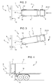
figure 1 illustrates a truck provided with a system for assisting a driver during approach operations according to the present invention; -
figures 2 and 3 illustrate the truck offigure 1 respectively in a correct and incorrect approach position with respect to an unloading bay; and -
figure 4 shows the truck offigures 1 to 3 provided with the assistance system according to the present invention, in a correct position with respect to the unloading bay. - With reference to the accompanying figures,
number 1 indicates a system for assisting the positioning of atruck 2. - More in detail, the
truck 2 comprises atruck tractor 3 and a semi-trailer 4 arranged behind thetruck tractor 3 with reference to a normal direction of travel of thetruck 2. The term normal direction of travel is used in the present description to mean a direction of travel in which thetruck tractor 3 moves forward ahead of thesemi-trailer 4. In particular the normal direction of travel is the direction opposite that indicated by the arrow infigure 2 . - The
truck tractor 3 comprises acab 5 and thesemi-trailer 4 comprises a horizontal loading floor 18 (figure 4 ). - The
semi-trailer 4 also comprises arear door 7 arranged in correspondence with atail end 6 of the truck arranged to the rear with reference to the normal direction of travel of thetruck 2. - In particular, the
system 1 is suitable to assist a driver while manoeuvring a truck to achieve the correct positioning of thetail end 6 with respect to anedge 10 of an unloading bay 8 (Figures 2 and 4 ). - The term manoeuvring to achieve the correct positioning refers to an operation, at the end of which a
loading surface 9 of thebay 8 delimited, on the side of thetruck 1, by theedge 10 is contiguous to aloading floor 18 of the semi-trailer 4 and thetail end 6 of thetruck 2 is parallel with and comes completely up against theedge 10 of thesurface 9. - Advantageously, the
system 1 comprises: - a
first sensor 11 mounted on apoint 12 of thetail end 6 and measuring a first dimension associated with the distance of saidpoint 12 from theedge 10; - a
second sensor 13 mounted on apoint 14, different from thepoint 12, of thetail end 6 and measuring a second dimension associated with the distance of thepoint 14 from theedge 10; and - a
processor 20 that receives the values of the first and of the second dimensions, and generates and outputs a first signal if the distance of thepoint 12 from theedge 10 is greater than the distance of thepoint 14 from theedge 10; theprocessor 20 generates a second signal, if the distance of thepoint 14 from theedge 10 is greater than the distance of thepoint 12 from theedge 10. - More in detail, the
sensors points edge 10 and receive said radiation reflected by saidedge 10. Thesensors points edge 10 according to the interval of time between the instants in which the radiation is emitted and that in which the reflected radiation is received. - Preferably, the
sensors - The
sensors cross-member 15 arranged in correspondence with thetail end 6 arranged below therear door 7 of thesemi-trailer 4. - The
processor 20 can be selectively operated by the driver. The activation of theprocessor 20 also determines the activation of thesensors - The
sensors points edge 10. Preferably, thesensors processor 20 in a local wireless mode and, in particular, using a Wi-Fi protocol. - The term local wireless mode refers to the fact that the distance between the
sensors processor 20 must be less than a previously defined value in order to enable the efficient transmission of said signals to theprocessor 20. - The
system 1 also comprises adisplay unit 21 incorporated in theprocessor 20, housed in thecab 5, suitable to display a first or asecond indication 22, 23 (figure 1 ) depending on whether theprocessor 20 generates respectively the first or the second signal. - In more detail, the
indication 22 tells the driver to turn the steering-wheel in a first direction (shown infigure 3 ) to move thepoint 14 towards theedge 10 more than thepoint 12. - The
indication 23 tells the driver to turn the steering-wheel in a second direction, opposite to the first, to move thepoint 12 towards theedge 10 more than thepoint 14. - The
display unit 21 also displays athird indication 24 showing the minimum value between the distances of thepoints tail end 6 is from theedge 10 as the truck approaches saidedge 10. - The
display unit 21 displays a fourth indication (not shown in the attached figures) when the distances between thepoints edge 10 are equal. Said fourth indication tells the driver that thetail end 6 is parallel with theedge 10 and that he can simply proceed in reverse without turning the steering-wheel to arrange thetail end 6 in the correct position with respect to thebay 8. - Lastly, the
display unit 21 displays a fifth indication (not shown in the attached figures) when thetail end 6 is up against theedge 10, i.e. when the distances between thepoints edge 10 are zero. In this way, the driver is informed of the fact that theloading floor 18 of thesemi-trailer 4 is contiguous and coplanar with thesurface 9. - The
processor 20 and thesensors - In use, the driver performs the approach operation by travelling towards the
bay 8 in reverse. - The
sensors points edge 10 and transmit this data to thereceiver 20. - In the case illustrated in
figure 3 , the distance of thepoint 12 from theedge 10 is less than the distance of thepoint 14 fromsaid edge 10. Theprocessor 20 therefore generates the second signal and thedisplay unit 21 displays theindication 23. The driver turns the steering-wheel in order to turn thetruck 2 in the direction shown infigure 3 . Thepoint 14 thus moves towards theedge 10 more than thepoint 12 moves towards saidedge 10. - Otherwise, if the distance of the
point 14 from theedge 10 is less than the distance of thepoint 12 fromsaid edge 10, theprocessor 20 generates the first signal and thedisplay unit 21 displays theindication 22. In that case, the driver uses the steering-wheel to turn thetruck 2 in the direction opposite to that indicated infigure 3 . He therefore turns the steering-wheel so that thepoint 12 moves towards theedge 10 more than thepoint 14 of thetail end 6. - The driver stops turning the steering-wheel when the
display unit 21 displays the fourth indication. - At this point, the
tail end 6 is parallel with the edge 10 (Figure 2 ) and the driver reverses the truck towards saidedge 10, observing theindication 24 on thedisplay unit 21 in order to know the distance between thetail end 6 and theedge 10 as this gradually decreases. - Once the
tail end 6 is parallel with theedge 10 and up against said edge 10 (Figure 4 ), thedisplay unit 21 displays the fifth indication. - At this point, the driver stops the truck, the
rear door 7 is opened and the goods can be conveniently unloaded. - The advantages that can be achieved with the
system 1 according to the present invention are apparent from an examination of the characteristics thereof. - In particular, the
system 1 enables the driver to approach theedge 10 of thebay 8 in reverse, without having to keep looking in the rear-view mirrors. - The
indications tail end 6 parallel with theedge 10 of thebay 8 are displayed continuously on thedisplay unit 21. - At the same time, the
indication 24 relating to the distance of thetail end 6 from theedge 10 of thebay 8 and the indication relating to the fact that thetail end 6 is parallel with and up against theedge 10 of thebay 8 are displayed continuously and progressively on thedisplay unit 21. - Thanks to said indications, the operations involved in order to approach the
bay 8 are made easy, repeatable and faster compared to the conventional solutions known in the prior art described at the beginning of this description. - Lastly, the
system 1 can also be applied effectively when thesemi-trailer 4 is coupled todifferent cabs 5. - In that case, the
sensors semi-trailer 4, thesemi-trailer 4 must be coupled to anothercab 5, and theprocessor 20 must be moved into thedifferent cab 5. - Lastly, it is clear that modifications and variations may be made to the
system 1 described and illustrated herein without departing from the scope of the present invention as set forth in the appended claims. - In particular, the
sensors tail end 6. - Moreover, the
system 1 could be provided with additional sensors to control other operating features of thetruck 1, for instance to verify the open or closed status of the doors of thecab 5. In that case, thedisplay unit 21 would display additional information associated with said other operating features.
Claims (12)
- System (1) for assisting a driver while manoeuvring a truck (2) towards a loading or unloading bay (8), characterized in that it comprises:- a first sensor (11) suitable to measure a first dimension associated with the value of the first distance of a first point (12) of a tail end (6) of said truck (2) with respect to said bay (8);- a second sensor (13) suitable to measure a second dimension associated with the value of a second distance of a second point (14) of said truck (2), different from said first point (12), of said tail end (6) with respect to said bay (8); and- processing means (20) suitable to receive the values of said first and second dimensions, and to generate a first signal if said first distance is greater than said second distance; said processing means (20) being suitable to generate a second signal, different from said first signal, if said second distance is greater than said first distance.
- System according to claim 1, characterized in that said processing means (20) comprise a display unit (21) to display a first and a second indication (22, 23); the first or the second indication (22, 23) being displayed when said processing means (20) generate respectively said first or said second signal.
- System according to claim 2, characterized in that said display unit (21) displays a third indication (24) representing the minimum value between said first and second distances.
- System according to claim 2 or 3, characterized in that said display unit (21) displays a fourth indication (21), when both of said first and second distances are zero.
- System according to any one of the previous claims, characterized in that said processing means (20) can be selectively operated.
- System according to claim 5, characterized in that the activation of said processing means (20) determines the activation of said first and second sensors (11, 13).
- System according to any one of the previous claims, characterised in that said processing means (20) are connected to said first and second sensors (11, 13) via a local wireless connection.
- System according to claim 7, characterized in that said wireless connection uses a Wi-Fi protocol.
- System according to any one of the previous claims, characterised in that at least one of said first and second sensors (11, 13) is an optical sensor.
- Truck (2) comprising a cab (5), said tail end (6), a loading floor (18) arranged between said cab (5) and said tail end (6), and a system (1) according to any one of the previous claims, characterized in that said first and second sensors (11, 13) are mounted on said tail end (6).
- Truck according to claim 10, when dependent on claim 2, characterized in that said display unit (21) is housed inside said cab (5).
- Truck according to claim 10 or 11, characterized in that said loading floor (18) is delimited, in correspondence with said tail end (6), by a cross-member (15); said first and second sensors (11, 13) being mounted on said cross-member (15).
Applications Claiming Priority (1)
| Application Number | Priority Date | Filing Date | Title |
|---|---|---|---|
| ITTO20080419 ITTO20080419A1 (en) | 2008-05-30 | 2008-05-30 | RIDER ASSISTANCE SYSTEM DURING A MANEUVER OF APPROACHING A TRUCK TO A BANQUET |
Publications (2)
| Publication Number | Publication Date |
|---|---|
| EP2127999A2 true EP2127999A2 (en) | 2009-12-02 |
| EP2127999A3 EP2127999A3 (en) | 2011-05-25 |
Family
ID=40303145
Family Applications (1)
| Application Number | Title | Priority Date | Filing Date |
|---|---|---|---|
| EP09156547A Withdrawn EP2127999A3 (en) | 2008-05-30 | 2009-03-27 | System for assisting a driver while manoeuvring a truck towards a loading or unloading bay |
Country Status (2)
| Country | Link |
|---|---|
| EP (1) | EP2127999A3 (en) |
| IT (1) | ITTO20080419A1 (en) |
Family Cites Families (3)
| Publication number | Priority date | Publication date | Assignee | Title |
|---|---|---|---|---|
| US6268803B1 (en) * | 1998-08-06 | 2001-07-31 | Altra Technologies Incorporated | System and method of avoiding collisions |
| DE10154612A1 (en) * | 2001-11-07 | 2003-05-22 | Bayerische Motoren Werke Ag | Steer by wire system for reversing towing vehicle with trailer, employs gap sensors to monitor changing angle between their longitudinal axes |
| DE202004001473U1 (en) * | 2004-01-30 | 2004-06-24 | Aspöck Systems GmbH | Ramp |
-
2008
- 2008-05-30 IT ITTO20080419 patent/ITTO20080419A1/en unknown
-
2009
- 2009-03-27 EP EP09156547A patent/EP2127999A3/en not_active Withdrawn
Also Published As
| Publication number | Publication date |
|---|---|
| ITTO20080419A1 (en) | 2009-11-30 |
| EP2127999A3 (en) | 2011-05-25 |
Similar Documents
| Publication | Publication Date | Title |
|---|---|---|
| US8457844B2 (en) | Parallel parking assistant system and method thereof | |
| US8576115B2 (en) | Vehicle length sensors | |
| US10119812B2 (en) | Trailer parameter identification system | |
| US10942269B2 (en) | Method for monitoring a surrounding area of a vehicle-trailer combination, monitoring device, driver assistance system and vehicle-trailer combination | |
| EP2148220B1 (en) | A motor-vehicle driving assistance system based on radar sensors for detecting the presence of obstacles in an area behind and/or beside the vehicle, particularly for parking assistance | |
| US8924090B2 (en) | Method for controlling operation of side step for vehicle | |
| GB2346495A (en) | Measuring distance from motor vehicle to rearward object | |
| US11498374B2 (en) | Dynamic lateral trailer hitch positioning system | |
| CN113661100A (en) | Method for estimating the wheelbase length of a trailer for a vehicle combination comprising more than one articulation angle | |
| US20200276934A1 (en) | Method and trailer-coupling assistance for assisting in the coupling process of a transportation vehicle reversing toward a trailer | |
| US12326493B2 (en) | Method and device for determining vehicle parameters | |
| US12037016B2 (en) | Control system and method for a trailer or dolly | |
| EP2127999A2 (en) | System for assisting a driver while manoeuvring a truck towards a loading or unloading bay | |
| US11952037B2 (en) | Method and apparatus in a motor vehicle for reversing multiple trailers | |
| US11866033B2 (en) | Method for estimating an effective length of a first vehicle segment of a vehicle combination | |
| US12434517B2 (en) | Method for assisting during a coupling process with a trailer, computing device, and assistance system for a vehicle | |
| US20240411015A1 (en) | Reversing Assistance Device and Method for Assisting a Vehicle During Reversing Operation | |
| US20250153733A1 (en) | Method for operating an assistance system, computer program product, and assistance system | |
| US12377876B2 (en) | Method for planning a driving trajectory defining a travelling path for a vehicle | |
| US20240166215A1 (en) | System and method for determining a length of a vehicle | |
| US20240428686A1 (en) | Device and Method for Assisting a Driver of a Combination at the Start of Travel, Assistance System for a Towing Vehicle, and Computer-Readable (Storage) Medium | |
| WO2021040664A1 (en) | Semi-trailer reverse parking support system and method |
Legal Events
| Date | Code | Title | Description |
|---|---|---|---|
| PUAI | Public reference made under article 153(3) epc to a published international application that has entered the european phase |
Free format text: ORIGINAL CODE: 0009012 |
|
| AK | Designated contracting states |
Kind code of ref document: A2 Designated state(s): AT BE BG CH CY CZ DE DK EE ES FI FR GB GR HR HU IE IS IT LI LT LU LV MC MK MT NL NO PL PT RO SE SI SK TR |
|
| AX | Request for extension of the european patent |
Extension state: AL BA RS |
|
| PUAL | Search report despatched |
Free format text: ORIGINAL CODE: 0009013 |
|
| AK | Designated contracting states |
Kind code of ref document: A3 Designated state(s): AT BE BG CH CY CZ DE DK EE ES FI FR GB GR HR HU IE IS IT LI LT LU LV MC MK MT NL NO PL PT RO SE SI SK TR |
|
| AX | Request for extension of the european patent |
Extension state: AL BA RS |
|
| AKY | No designation fees paid | ||
| REG | Reference to a national code |
Ref country code: DE Ref legal event code: R108 |
|
| STAA | Information on the status of an ep patent application or granted ep patent |
Free format text: STATUS: THE APPLICATION IS DEEMED TO BE WITHDRAWN |
|
| REG | Reference to a national code |
Ref country code: DE Ref legal event code: R108 Effective date: 20120201 |
|
| 18D | Application deemed to be withdrawn |
Effective date: 20101001 |