EP2127954A1 - A motor vehicle safety device - Google Patents
A motor vehicle safety device Download PDFInfo
- Publication number
- EP2127954A1 EP2127954A1 EP08251822A EP08251822A EP2127954A1 EP 2127954 A1 EP2127954 A1 EP 2127954A1 EP 08251822 A EP08251822 A EP 08251822A EP 08251822 A EP08251822 A EP 08251822A EP 2127954 A1 EP2127954 A1 EP 2127954A1
- Authority
- EP
- European Patent Office
- Prior art keywords
- inflatable element
- safety device
- door
- motor vehicle
- pillar
- Prior art date
- Legal status (The legal status is an assumption and is not a legal conclusion. Google has not performed a legal analysis and makes no representation as to the accuracy of the status listed.)
- Granted
Links
- 239000000463 material Substances 0.000 claims description 7
- 238000004891 communication Methods 0.000 claims description 5
- 230000021715 photosynthesis, light harvesting Effects 0.000 description 7
- 238000000034 method Methods 0.000 description 3
- 230000008878 coupling Effects 0.000 description 2
- 238000010168 coupling process Methods 0.000 description 2
- 238000005859 coupling reaction Methods 0.000 description 2
- 238000006073 displacement reaction Methods 0.000 description 2
- 239000012530 fluid Substances 0.000 description 2
- 238000009434 installation Methods 0.000 description 2
- 230000008569 process Effects 0.000 description 2
- 230000000717 retained effect Effects 0.000 description 2
- 239000000853 adhesive Substances 0.000 description 1
- 230000001070 adhesive effect Effects 0.000 description 1
- 230000004075 alteration Effects 0.000 description 1
- 230000005540 biological transmission Effects 0.000 description 1
- 230000000694 effects Effects 0.000 description 1
- 239000013536 elastomeric material Substances 0.000 description 1
- 238000004519 manufacturing process Methods 0.000 description 1
- 230000007246 mechanism Effects 0.000 description 1
- 239000002184 metal Substances 0.000 description 1
- 238000012986 modification Methods 0.000 description 1
- 230000004048 modification Effects 0.000 description 1
- 230000001681 protective effect Effects 0.000 description 1
- 239000004753 textile Substances 0.000 description 1
Images





Classifications
-
- B—PERFORMING OPERATIONS; TRANSPORTING
- B60—VEHICLES IN GENERAL
- B60R—VEHICLES, VEHICLE FITTINGS, OR VEHICLE PARTS, NOT OTHERWISE PROVIDED FOR
- B60R21/00—Arrangements or fittings on vehicles for protecting or preventing injuries to occupants or pedestrians in case of accidents or other traffic risks
- B60R21/02—Occupant safety arrangements or fittings, e.g. crash pads
- B60R21/16—Inflatable occupant restraints or confinements designed to inflate upon impact or impending impact, e.g. air bags
- B60R21/23—Inflatable members
-
- B—PERFORMING OPERATIONS; TRANSPORTING
- B60—VEHICLES IN GENERAL
- B60J—WINDOWS, WINDSCREENS, NON-FIXED ROOFS, DOORS, OR SIMILAR DEVICES FOR VEHICLES; REMOVABLE EXTERNAL PROTECTIVE COVERINGS SPECIALLY ADAPTED FOR VEHICLES
- B60J5/00—Doors
- B60J5/04—Doors arranged at the vehicle sides
- B60J5/042—Reinforcement elements
-
- B—PERFORMING OPERATIONS; TRANSPORTING
- B60—VEHICLES IN GENERAL
- B60J—WINDOWS, WINDSCREENS, NON-FIXED ROOFS, DOORS, OR SIMILAR DEVICES FOR VEHICLES; REMOVABLE EXTERNAL PROTECTIVE COVERINGS SPECIALLY ADAPTED FOR VEHICLES
- B60J5/00—Doors
- B60J5/10—Doors arranged at the vehicle rear
- B60J5/101—Doors arranged at the vehicle rear for non-load transporting vehicles, i.e. family cars including vans
- B60J5/107—Doors arranged at the vehicle rear for non-load transporting vehicles, i.e. family cars including vans constructional details, e.g. about door frame, panels, materials used, reinforcements
-
- B—PERFORMING OPERATIONS; TRANSPORTING
- B60—VEHICLES IN GENERAL
- B60R—VEHICLES, VEHICLE FITTINGS, OR VEHICLE PARTS, NOT OTHERWISE PROVIDED FOR
- B60R19/00—Wheel guards; Radiator guards, e.g. grilles; Obstruction removers; Fittings damping bouncing force in collisions
- B60R2019/007—Means for adjusting or regulating the crash absorption capacity of the vehicle, e.g. when detecting an impending collision
-
- B—PERFORMING OPERATIONS; TRANSPORTING
- B60—VEHICLES IN GENERAL
- B60R—VEHICLES, VEHICLE FITTINGS, OR VEHICLE PARTS, NOT OTHERWISE PROVIDED FOR
- B60R21/00—Arrangements or fittings on vehicles for protecting or preventing injuries to occupants or pedestrians in case of accidents or other traffic risks
- B60R21/02—Occupant safety arrangements or fittings, e.g. crash pads
- B60R21/04—Padded linings for the vehicle interior ; Energy absorbing structures associated with padded or non-padded linings
- B60R21/0428—Padded linings for the vehicle interior ; Energy absorbing structures associated with padded or non-padded linings associated with the side doors or panels, e.g. displaced towards the occupants in case of a side collision
Definitions
- the present invention relates to a motor vehicle safety device and, more particularly, relates to a safety device for maintaining a clearance between adjacent structural members of a motor vehicle in the event of a crash.
- the doors of motor vehicles are conventionally mounted using a combination of hinges and releasable latches in order to provide opening doors which can be securely closed during operation of a motor vehicle and locked shut when the motor vehicle is not in use.
- an important secondary function of such door hinges and latches is to ensure sufficient integrity of the complete motor vehicle structure in the event that the motor vehicle should be involved in a crash. It is a goal of vehicle manufacturers to seek to reduce intrusion of the structure of the motor vehicle into the interior cabin as a result of an accident, and also to retain the shape of the vehicle's safety cage.
- the doors of a motor vehicle play an important function in contributing to vehicle strength and, indeed, are designed to allow dissipation of some of the collision energy in a motor vehicle structure, through the inner and outer door structure. Crash energy is transmitted to the doors of a motor vehicle through the door hinges and latches, but due to necessary assembly clearances arising from their primary function, the level of such energy transmission is typically relatively low.
- a problem with known door structures of the general type described above is that after a severe accident, the door hinges and/or latches can become deformed to such a degree that the door can no longer be easily opened which can have serious implications in the event that access is required to the interior cabin by emergency services in order to tend to an occupant of a crashed vehicle.
- the present invention provides a safety device for maintaining a clearance between adjacent structural members of a motor vehicle in the event of a crash, the device being characterized by the provision of an inflatable element mounted to one of a pair of substantially adjacent structural members of a motor vehicle, the inflatable element being configured for inflation within a space initially formed between said pair of structural members.
- the inflatable element has a pre-crashed configuration in which is does not intrude in to said space.
- said inflatable element is configured to couple said structural members to one another when inflated and to prevent substantially complete closure of the space between them in the event of a crash.
- one of said structural members is moveable in order to provide access to an interior space of the motor vehicle, and the other of said structural members is fixed.
- said inflatable element is mounted to the fixed member.
- said moveable member is a door and said fixed member is a pillar.
- said moveable member is a bonnet (sometimes also known as a hood) or a boot-lid (also sometimes known as a trunk-lid).
- said inflatable element is provided in the region of a releasable latch between the moveable member and the fixed member.
- the inflatable element is provided in the region of a hinge between the moveable member and the fixed member.
- the inflatable element is provided with a vent aperture, the vent aperture being arranged to close against one of the structural members during inflation.
- the inflatable elements take the form of an air-bag formed of a substantially elastically deformable material.
- the inflatable element is an air-bag formed of a substantially plastically deformable material.
- the inflatable element has an inflating capacity of between 50 cm 3 and 200 cm 3 .
- the inflatable element is elongate in form.
- the safety device further comprises a pyrotechnic gas-generator provided in fluid-communication with the inflatable element for inflation thereof.
- the safety device of the present invention addresses the aforementioned problems associated with more conventional closing door arrangements by effectively filling up the space initially located between the two structural members (most preferably a door and structural pillar), thereby coupling the two structural members to one another.
- the arrangement has been found not only to prevent significant deformation of the door hinges and latch arrangements, but also to provide for improved energy dissipation between the two structural members.
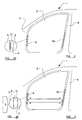
- FIG. 1 part of the structure of a motor vehicle 1 is illustrated showing a door 2 in a closed position between a structural A-pillar 3 and a structural B-pillar 4 of the motor vehicle.
- the door is pivotally mounted to the A-pillar 3 by a hinge 5, and is releasably connected to the B-pillar 4 by a releasable latch 6.
- the hinge 5 and latch 6 are only illustrated schematically.
- Figure 2 is a view corresponding generally to that of Figure 1 , but illustrates the motor vehicle 1 fitted with a safety device in accordance with the present invention, with the hinge 5 and the latch 6 having been omitted for the sake of clarity.
- a pair of inflatable elements 9, 10 are provided which preferably take the form of inflatable air-bags which are initially provided in a tightly packed configuration.
- the two inflatable elements are each provided within the respective space formed between the door 2 and the two pillars, 3, 4, that is within the door jambs.
- Each of the inflatable elements 9, 10 have an initial configuration such as that illustrated schematically in Figure 2a with regard to the front element 9 between the A-pillar and the door 2.
- the inflatable element 9 is shown in an initial uninflatated condition in which it is mounted to the A-pillar and in which it is tightly packed so as not to intrude significantly in to the space 11 formed between the A-pillar 3 and the door 2.
- the rear inflatable element 10 has a similar configuration in its initial condition.
- the inflatable elements 9, 10 Upon actuation of the safety device, for example upon receipt of a signal from a crash sensor or a predictive "pre-crash” sensor, the inflatable elements 9, 10 are inflated so as to adopt configurations such as that illustrated schematically in Figure 3a with regard to the front inflatable element 9. It will thus be appreciated that when the safety device is actuated, the inflatable elements 9, 10 are inflated so as to substantially fill the space 11 between the door 2 and the adjacent pillar 3 (or 4), or at least so as to extend substantially completely across the space 11, thereby effectively coupling the door with the adjacent pillar.
- FIG 4 is a schematic illustration showing the preferred dimensions for an inflatable element 9, 10 of the type described above for installation in a conventional motor vehicle.
- the inflatable element illustrated is the rear inflatable element 10 of the arrangement shown in Figures 2 and 3 and so is located in the space 11 formed between the door 2 and the B-pillar 4 of the motor vehicle.
- the inflatable element 10 is shown in its inflated condition within the space 11 and it will be seen that the inflatable element has a generally elongate configuration having a vertical height (h) which is significantly greater than a transverse depth (d) and a longitudinal width (w).
- the preferred inflatable element 10 For installation in conventional motor vehicles, the preferred inflatable element 10 has a height (h) of 0.3 metres, a depth (d) of 0.03 metres and a width (w) of 0.01 metres giving an inflatable volume of approximately 90 cm 3 .
- the preferred inflatable element 10 could incorporate inflatable elements having an inflatable volume of between 50 and 200 cm 3 , and more preferably 80 and 100 cm 3 , As will be appreciated, large vehicles such as SUVs are likely to require larger volume inflatable elements than smaller vehicles such as city cars.
- the above-prescribed air-bag is rather small both in terms of overall inflated dimension, and also in terms of its internal inflatable volume.
- a small inflatable element is necessary in order for it to be accommodated in the region of the small space 11 between the motor vehicle door and the adjacent structural pillar of the motor vehicle and so in order to provide sufficiently quick inflation of the inflatable element 10, it is proposed to provide the element in fluid communication with a pyrotechnic gas generator configured to receive an actuating signal from a crash sensor or a pre-crash sensor and to direct an appropriate volume of inflating gas very quickly in to the internal volume of the inflatable element 10.
- the inflatable elements must become substantially fully inflated within 15 milliseconds of receipt of an appropriate actuating signal from the sensor, and an internal inflation pressure of approximately 100bar has been found to be particularly advantageous.
- This level of pressure, in an air-bag of the preferred dimensions indicated above, has been found to transmit a load of approximately 90kN between the door and the pillar.
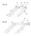
- FIG 5a there is illustrated a preferred fold configuration for the initially tightly packed inflatable elements 9, 10.
- the elongate inflatable element 10 is initially zig-zag folded in the region of its longitudinal side edges 12, 13 so as to have re-entrant side regions running longitudinally.
- figure 5a illustrates the folded inflatable element in a slightly opened or pulled-apart configuration for ease of illustration.
- the re-entrant regions 14, 15 will be tightly received between the two opposing side faces of the inflatable element 10.
- Figure 5b illustrates the inflatable element 10 of figure 5a in a position generally representative of its inflated configuration from which it will be appreciated that during inflation of the elements 10, the initial re-entrant regions 14, 15 are blown outwardly so as to adopt the positions illustrated in figure 5b .
- the preferred form of inflatable element 10 has an initial "bellows"-type shape which has the effect that during the initial stages of inflation, the element 10 quickly gains an increased width (w) and so quickly couples between the door structure and the adjacent pillar structure of the motor vehicle.
- the space 11 between the structure of the door and the adjacent pillars is very limited in size and so, as shown in figure 6a, 6b and 6c , the initially tightly packed inflatable element 10 is preferably mounted to the pillars 3, 4 so as to be received within a shallow recess 16 formed along the pillar and in communication with the space 11.
- the tightly packed inflatable element 10 (which can initially be retained within a rupturable protective wrapper) can be mounted within the recess 16 in any one of a number of ways.
- figure 6a illustrates the inflatable element 10 being glued to the pillar 4, within the recess 16, by a layer of suitable adhesive 17.
- the packaged inflatable element 10 can be secured to the pillar 4 by a number of bolts 18, or rivets or the like which are received through appropriate mounting apertures provided through the surface of the pillar 4.
- Figure 6c illustrates an alternative mounting arrangement in which the packaged inflatable element 10 is retained behind a rupturable tear-cover 19 which is secured to the pillar 4 so as to substantially cover the recess 16.
- the inflatable element 10 is provided with an inflator which preferably takes the form of a small pyrotechnic gas generator.
- Figure 7a illustrates an arrangement in which the gas generator 19 is mounted within the structural pillar 4 of the motor vehicle, behind the recess 16, the gas generator 19 having an outlet portion 20 which extends through an aperture formed in the surface of the pillar 4 so as to communicate fluidly with the inflatable element 10.
- FIG 7b An alternative configuration is illustrated in figure 7b in which a small inflator recess 21 is provided in the structural pillar 4 and which opens into the shallow recess 16. The inflator recess 21 receives the gas generator 19 for fluid communication with the inflatable element 10.
- each inflatable element 9, 10 is configured for immediate deflation after the accident has occurred.
- Figure 8a illustrates, in perspective view, the inflatable element 10 in an initial, substantially uninflated, condition within the space 11 between the structure of a door 2 and the B-pillar 4 of a motor vehicle.
- the vent aperture 21 takes the form of an elongate oval hole provided in the inflatable element 10 so as to be directed towards the structure of the door 2.
- the vent hole 21 will initially be obscured due to the initial folded configuration of the inflatable element 10 so as to allow very quick initial inflation of the element without significant escape of inflating gas through the vent hole 21.
- Figure 8b illustrates the arrangement of figure 8a in a condition in which the inflatable element 10 is substantially fully inflated, thereby extending entirely across the gap 11 so as to couple the door 2 to the adjacent pillar 4.
- the region of the inflatable element 10 within which the vent hole 21 is provided has been pressed against the rear surface of the door structure 2.
- the vent aperture 21 becomes effectively closed against the structure of the door 2, thereby preventing the outflow of inflating gas through the aperture 21 during later stages of the inflating process.
- the vent aperture 21 becomes unobstructed once pressurisation by the inflating gas has stopped and once there are no more crash forces acting on the motor vehicle.
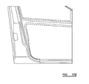
- Figure 9 illustrates the general structure of a motor vehicle A-pillar 3, door 2 and B-pillar 4, viewed from the interior of the motor vehicle.
- the recess 16 within which the inflatable element 10 is provided can clearly be seen to be formed generally in the region of the door latch mechanism 6.
- a front inflatable element 9 is not illustrated in figure 9 .
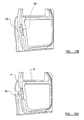
- Figure 10a represents an enlarged view of the region of figure 9 identified by the square 21 with a mesh notation added so that the subsequent deformation forces can be seen more easily.
- Figure 10a illustrates the arrangement before actuation.
- Figure 10b corresponds generally to figure 10a , but is illustrated from a slightly more rearward view point, and illustrates the arrangement during an initial stage of actuation in which the gas generator 19 has been fired in order to inflate the inflatable element 10.
- Figure 10c shows the inflatable element 10 in a substantially fully inflated condition in which it couples the B-pillar 4 to the structure of the door 2, and also shows the structure of the motor vehicle in a deformed condition due to crash forces.
- Preferred embodiments of the invention incorporate inflatable elements 10 in the form of air-bags made of elastically deformable material such as reinforced textile material or an elastomeric material.
- the preferred shapes for such inflatable air-bags include elongate cylinders having a substantially circular cross-section, elongate frustoconical arrangements or elongate air-bag configurations having a substantially rectangular cross-section.
- plastically deformable air-bags made from materials such as plastic or metal.
Landscapes
- Engineering & Computer Science (AREA)
- Mechanical Engineering (AREA)
- Body Structure For Vehicles (AREA)
- Superstructure Of Vehicle (AREA)
- Air Bags (AREA)
Abstract
Description
- The present invention relates to a motor vehicle safety device and, more particularly, relates to a safety device for maintaining a clearance between adjacent structural members of a motor vehicle in the event of a crash.
- The doors of motor vehicles are conventionally mounted using a combination of hinges and releasable latches in order to provide opening doors which can be securely closed during operation of a motor vehicle and locked shut when the motor vehicle is not in use. However, an important secondary function of such door hinges and latches is to ensure sufficient integrity of the complete motor vehicle structure in the event that the motor vehicle should be involved in a crash. It is a goal of vehicle manufacturers to seek to reduce intrusion of the structure of the motor vehicle into the interior cabin as a result of an accident, and also to retain the shape of the vehicle's safety cage. The doors of a motor vehicle play an important function in contributing to vehicle strength and, indeed, are designed to allow dissipation of some of the collision energy in a motor vehicle structure, through the inner and outer door structure. Crash energy is transmitted to the doors of a motor vehicle through the door hinges and latches, but due to necessary assembly clearances arising from their primary function, the level of such energy transmission is typically relatively low.
- As will also be appreciated, a problem with known door structures of the general type described above, is that after a severe accident, the door hinges and/or latches can become deformed to such a degree that the door can no longer be easily opened which can have serious implications in the event that access is required to the interior cabin by emergency services in order to tend to an occupant of a crashed vehicle.
- It is therefore an object of the present invention to provide a safety device which seeks to address the above mentioned problems.
- Accordingly, the present invention provides a safety device for maintaining a clearance between adjacent structural members of a motor vehicle in the event of a crash, the device being characterized by the provision of an inflatable element mounted to one of a pair of substantially adjacent structural members of a motor vehicle, the inflatable element being configured for inflation within a space initially formed between said pair of structural members.
- Preferably the inflatable element has a pre-crashed configuration in which is does not intrude in to said space.
- Advantageously said inflatable element is configured to couple said structural members to one another when inflated and to prevent substantially complete closure of the space between them in the event of a crash.
- Conveniently one of said structural members is moveable in order to provide access to an interior space of the motor vehicle, and the other of said structural members is fixed.
- Advantageously said inflatable element is mounted to the fixed member.
- Conveniently said moveable member is a door and said fixed member is a pillar.
- Alternatively said moveable member is a bonnet (sometimes also known as a hood) or a boot-lid (also sometimes known as a trunk-lid).
- Preferably said inflatable element is provided in the region of a releasable latch between the moveable member and the fixed member.
- Advantageously the inflatable element is provided in the region of a hinge between the moveable member and the fixed member.
- Conveniently the inflatable element is provided with a vent aperture, the vent aperture being arranged to close against one of the structural members during inflation.
- Preferably the inflatable elements take the form of an air-bag formed of a substantially elastically deformable material.
- Alternatively, the inflatable element is an air-bag formed of a substantially plastically deformable material.
- Preferably the inflatable element has an inflating capacity of between 50 cm3 and 200 cm3.
- Advantageously, the inflatable element is elongate in form.
- Preferably the safety device further comprises a pyrotechnic gas-generator provided in fluid-communication with the inflatable element for inflation thereof.
- It has been found that the safety device of the present invention addresses the aforementioned problems associated with more conventional closing door arrangements by effectively filling up the space initially located between the two structural members (most preferably a door and structural pillar), thereby coupling the two structural members to one another. The arrangement has been found not only to prevent significant deformation of the door hinges and latch arrangements, but also to provide for improved energy dissipation between the two structural members.
- So that the invention may be more readily understood, and so that further features thereof may be appreciated, embodiments of the invention will now be described, by way of example, with reference to the accompanying drawings, in which:
-
Figure 1 is a schematic side view illustrating a generally conventional motor vehicle door-mounting. -
Figure 2 is a view corresponding generally to that ofFigure 1 , illustrating a safety device in accordance with the present invention comprising a pair of inflatable elements; -
Figure 2A is an enlarged sectional view illustrating one of the inflatable elements in its initial, uninflated, position between a structural pillar of the motor vehicle and the door; -
Figure 3 is a view corresponding generally to that ofFigure 2 illustrating the safety device after actuation; -
Figure 3A is a view corresponding generally to that ofFigure 2A , but illustrating the inflatable element in an inflated condition; -
Figure 4 is a schematic perspective view illustrating the preferred inflated dimensions of an inflatable element for use in accordance with the present invention; -
Figure 5a is a schematic perspective view showing a preferred folded configuration for the inflatable element, prior to actuation; -
Figure 5b is a view corresponding generally to that ofFigure 5a , but illustrating the inflatable element in its inflated condition; -
Figures 6a, 6b and 6c illustrate alternative ways in which an inflatable element can be mounted within the door jamb of a motor vehicle for use in accordance with the present invention; -
Figures 7a and 7b are views corresponding generally to those offigures 6a to 6c illustrating two alternative ways in which an inflator can be mounted with respect to the inflatable element; -
Figure 8a is a schematic view illustrating an inflatable element in its initial, uninflated, position within a door jamb; -
Figure 8b is a view corresponding generally to that ofFigure 8a , but illustrating the inflatable element in a substantially fully inflated condition in which a vent aperture provided within the inflatable element is pressed against the door structure; -
Figure 9 is a view illustrating a closed vehicle door extending between an A-pillar and a B-pillar of a motor vehicle structure, viewed from the inside of the motor vehicle cabin; -
Figure 10a is an enlarged view of the arrangement shown inFigure 9 , focusing on the region of the B-pillar and the rear part of the door structure; -
Figure 10b is a perspective view, corresponding generally to that offigure 10a but from a more rearward viewpoint, illustrating the arrangement after inflation of the inflatable element; -
Figure 10c is a view corresponding generally to that offigure 10b , but illustrating the arrangement following deformation of the vehicle structure and the door in a crash-situation; -
Figure 11 is a graph showing the improved energy dissipation characteristic of a vehicle provided with a safety device in accordance with the present invention. - Referring initially to
Figure 1 , part of the structure of amotor vehicle 1 is illustrated showing adoor 2 in a closed position between astructural A-pillar 3 and a structural B-pillar 4 of the motor vehicle. The door is pivotally mounted to theA-pillar 3 by ahinge 5, and is releasably connected to the B-pillar 4 by areleasable latch 6. Thehinge 5 andlatch 6 are only illustrated schematically. - In the event that a
motor vehicle 1 having a generally conventional door structure such as that illustrated inFigure 1 is involved in a crash, the collision forces are transmitted between theA-pillar 3 and thedoor 2 in the region of thehinge 5 as illustrated schematically by thearrows 7, and between the B-pillar 4 and thedoor structure 2 in the region of thelatch 6 as illustrated schematically by thearrows 8. As will be appreciated, this means that the collision forces are transmitted across a relatively small region and also can only be transmitted in this manner when the manufacturing tolerances of the hinge and latch arrangements have taken up an initial degree of deflection without any dissipation of energy. -
Figure 2 is a view corresponding generally to that ofFigure 1 , but illustrates themotor vehicle 1 fitted with a safety device in accordance with the present invention, with thehinge 5 and thelatch 6 having been omitted for the sake of clarity. A pair ofinflatable elements door 2 and the two pillars, 3, 4, that is within the door jambs. - Each of the
inflatable elements Figure 2a with regard to thefront element 9 between the A-pillar and thedoor 2. Theinflatable element 9 is shown in an initial uninflatated condition in which it is mounted to the A-pillar and in which it is tightly packed so as not to intrude significantly in to thespace 11 formed between theA-pillar 3 and thedoor 2. The rearinflatable element 10 has a similar configuration in its initial condition. - Upon actuation of the safety device, for example upon receipt of a signal from a crash sensor or a predictive "pre-crash" sensor, the
inflatable elements Figure 3a with regard to the frontinflatable element 9. It will thus be appreciated that when the safety device is actuated, theinflatable elements space 11 between thedoor 2 and the adjacent pillar 3 (or 4), or at least so as to extend substantially completely across thespace 11, thereby effectively coupling the door with the adjacent pillar. When theinflatable elements A-pillar 3, via the frontinflatable element 9 to the structure of thedoor 2, from where it will then be transmitted through the structure of the door and on to the B-pillar 4 via the rearinflatable element 10. As will also be appreciated, with the twoinflatable elements space 11 at the front and rear of the door, substantial deformation of the hinge and the latch will be prevented, thereby ensuring relatively easy opening of the door after a crash. - Whilst the invention has been described in general terms with regard to
figures 2 and 3 in terms of an embodiment incorporating two inflatable elements (one located at the front of a door and one located to the rear of a door), it should be appreciated that alternative embodiments of the invention could comprise only one inflatable element located either at the front of the door in the region of the hinge, or at the rear of the door in the region of the latch. -
Figure 4 is a schematic illustration showing the preferred dimensions for aninflatable element inflatable element 10 of the arrangement shown inFigures 2 and 3 and so is located in thespace 11 formed between thedoor 2 and the B-pillar 4 of the motor vehicle. Theinflatable element 10 is shown in its inflated condition within thespace 11 and it will be seen that the inflatable element has a generally elongate configuration having a vertical height (h) which is significantly greater than a transverse depth (d) and a longitudinal width (w). For installation in conventional motor vehicles, the preferredinflatable element 10 has a height (h) of 0.3 metres, a depth (d) of 0.03 metres and a width (w) of 0.01 metres giving an inflatable volume of approximately 90 cm3. However, it is envisaged that variants of the invention could incorporate inflatable elements having an inflatable volume of between 50 and 200 cm3, and more preferably 80 and 100 cm3, As will be appreciated, large vehicles such as SUVs are likely to require larger volume inflatable elements than smaller vehicles such as city cars. - It will be appreciated by those of skill in the art of motor vehicle safety devices incorporating inflatable air-bags that the above-prescribed air-bag is rather small both in terms of overall inflated dimension, and also in terms of its internal inflatable volume. Such a small inflatable element is necessary in order for it to be accommodated in the region of the
small space 11 between the motor vehicle door and the adjacent structural pillar of the motor vehicle and so in order to provide sufficiently quick inflation of theinflatable element 10, it is proposed to provide the element in fluid communication with a pyrotechnic gas generator configured to receive an actuating signal from a crash sensor or a pre-crash sensor and to direct an appropriate volume of inflating gas very quickly in to the internal volume of theinflatable element 10. In preferred arrangements, the inflatable elements must become substantially fully inflated within 15 milliseconds of receipt of an appropriate actuating signal from the sensor, and an internal inflation pressure of approximately 100bar has been found to be particularly advantageous. This level of pressure, in an air-bag of the preferred dimensions indicated above, has been found to transmit a load of approximately 90kN between the door and the pillar. - Turning now to consider
figure 5a , there is illustrated a preferred fold configuration for the initially tightly packedinflatable elements inflatable element 10 is initially zig-zag folded in the region of its longitudinal side edges 12, 13 so as to have re-entrant side regions running longitudinally. It should be appreciated, however, thatfigure 5a illustrates the folded inflatable element in a slightly opened or pulled-apart configuration for ease of illustration. When the inflatable element is initially properly packed, there-entrant regions inflatable element 10. -
Figure 5b illustrates theinflatable element 10 offigure 5a in a position generally representative of its inflated configuration from which it will be appreciated that during inflation of theelements 10, the initialre-entrant regions figure 5b . It should therefore be appreciated that the preferred form ofinflatable element 10 has an initial "bellows"-type shape which has the effect that during the initial stages of inflation, theelement 10 quickly gains an increased width (w) and so quickly couples between the door structure and the adjacent pillar structure of the motor vehicle. - As will be appreciated, the
space 11 between the structure of the door and the adjacent pillars is very limited in size and so, as shown infigure 6a, 6b and 6c , the initially tightly packedinflatable element 10 is preferably mounted to thepillars shallow recess 16 formed along the pillar and in communication with thespace 11. The tightly packed inflatable element 10 (which can initially be retained within a rupturable protective wrapper) can be mounted within therecess 16 in any one of a number of ways. For example,figure 6a illustrates theinflatable element 10 being glued to thepillar 4, within therecess 16, by a layer ofsuitable adhesive 17. Alternatively, as illustrated infigure 6b , the packagedinflatable element 10 can be secured to thepillar 4 by a number ofbolts 18, or rivets or the like which are received through appropriate mounting apertures provided through the surface of thepillar 4.Figure 6c illustrates an alternative mounting arrangement in which the packagedinflatable element 10 is retained behind a rupturable tear-cover 19 which is secured to thepillar 4 so as to substantially cover therecess 16. - As indicated above, the
inflatable element 10 is provided with an inflator which preferably takes the form of a small pyrotechnic gas generator.Figure 7a illustrates an arrangement in which thegas generator 19 is mounted within thestructural pillar 4 of the motor vehicle, behind therecess 16, thegas generator 19 having anoutlet portion 20 which extends through an aperture formed in the surface of thepillar 4 so as to communicate fluidly with theinflatable element 10. An alternative configuration is illustrated infigure 7b in which asmall inflator recess 21 is provided in thestructural pillar 4 and which opens into theshallow recess 16. Theinflator recess 21 receives thegas generator 19 for fluid communication with theinflatable element 10. - As will be appreciated, as one of the main functions of the invention is to ensure that the doors of a motor vehicle can be opened relatively easily after an accident, it is preferable for each
inflatable element vent aperture 21 such as that illustrated schematically infigure 8a. Figure 8a illustrates, in perspective view, theinflatable element 10 in an initial, substantially uninflated, condition within thespace 11 between the structure of adoor 2 and the B-pillar 4 of a motor vehicle. Thevent aperture 21 takes the form of an elongate oval hole provided in theinflatable element 10 so as to be directed towards the structure of thedoor 2. However, in preferred embodiments, it is envisaged that thevent hole 21 will initially be obscured due to the initial folded configuration of theinflatable element 10 so as to allow very quick initial inflation of the element without significant escape of inflating gas through thevent hole 21. -
Figure 8b illustrates the arrangement offigure 8a in a condition in which theinflatable element 10 is substantially fully inflated, thereby extending entirely across thegap 11 so as to couple thedoor 2 to theadjacent pillar 4. Here, it can be seen that the region of theinflatable element 10 within which thevent hole 21 is provided has been pressed against the rear surface of thedoor structure 2. In this way, thevent aperture 21 becomes effectively closed against the structure of thedoor 2, thereby preventing the outflow of inflating gas through theaperture 21 during later stages of the inflating process. However, thevent aperture 21 becomes unobstructed once pressurisation by the inflating gas has stopped and once there are no more crash forces acting on the motor vehicle. This is because whilst the vehicle frame and door is compressed in a crash, thespace 11 between thedoor 2 and thepillar 4 is reduced slightly. However, after the crash, a degree of relaxation occurs within the structure of the motor vehicle frame and the door, with the result that thegap 11 relaxes slightly upon completion of the accident, thereby moving the surface of thedoor 2 slightly away from thevent aperture 21, and allowing the inflating gas within theelement 10 to vent through theaperture 21. This causes theinflatable element 10 to deflate slightly, thereby allowing the door to be opened immediately after the vehicle comes to a rest. -
Figure 9 illustrates the general structure of a motor vehicle A-pillar 3,door 2 and B-pillar 4, viewed from the interior of the motor vehicle. Therecess 16 within which theinflatable element 10 is provided can clearly be seen to be formed generally in the region of thedoor latch mechanism 6. For the sake of simplicity, a frontinflatable element 9 is not illustrated infigure 9 . -
Figure 10a represents an enlarged view of the region offigure 9 identified by the square 21 with a mesh notation added so that the subsequent deformation forces can be seen more easily.Figure 10a illustrates the arrangement before actuation. -
Figure 10b corresponds generally tofigure 10a , but is illustrated from a slightly more rearward view point, and illustrates the arrangement during an initial stage of actuation in which thegas generator 19 has been fired in order to inflate theinflatable element 10.Figure 10c shows theinflatable element 10 in a substantially fully inflated condition in which it couples the B-pillar 4 to the structure of thedoor 2, and also shows the structure of the motor vehicle in a deformed condition due to crash forces. - Preferred embodiments of the invention incorporate
inflatable elements 10 in the form of air-bags made of elastically deformable material such as reinforced textile material or an elastomeric material. The preferred shapes for such inflatable air-bags include elongate cylinders having a substantially circular cross-section, elongate frustoconical arrangements or elongate air-bag configurations having a substantially rectangular cross-section. However, it should be appreciated that variants of the invention are also envisaged which might incorporate plastically deformable air-bags made from materials such as plastic or metal. - It has been found that with the safety device of the present invention installed in a generally otherwise conventional motor vehicle, energy dissipation across a door aperture is significantly improved. This can be seen from a consideration of
figure 11 which represents a plot of force against displacement. Thelower line 21 represents the energy dissipation characteristic of a motor vehicle without the safety device of the present invention, whereasline 22 illustrates the energy dissipation characteristic of a similar vehicle with a device in accordance with the present invention installed. As can be seen, the vehicle incorporating the safety device of the present invention displays a significantly improved energy dissipation characteristic across a significant range of displacement. - Of course, as will readily be appreciated by those of skill in this technical field, although the present invention has been described with particular reference to certain embodiments, it is envisaged that various modifications or alterations could be made without departing from the scope of the presently claimed invention. For example, although the invention has been described above with reference to particular embodiments in which inflatable elements are provided between a structural pillar of a motor vehicle and an adjacent moveable door panel, the invention could also be installed in the space between a structural roof rail or door-sill of a motor vehicle and an associated moveable door panel in order to provide improved energy dissipation in a rollover accident and also to allow easy door opening in the event of a rollover accident. Furthermore, the inflatable elements of the present invention could also be installed between a bonnet or boot-lid of a motor vehicle and the adjacent structural parts of a motor vehicle.
- When using a specification and claims, the terms "comprises" and "comprising" and variations thereof mean that the specified features, steps or integers are included. The terms are not to be interpreted to exclude the presence of other features, steps or components.
- The features disclosing the foregoing description, or in the following claims, or in the accompanying drawings, expressed in their specific forms are in terms of a means for performing the disclosed function, or a method or process for obtaining a disclosed result, as appropriate, may, separately, or in any combination of such features, be utilised for realising an invention in diverse forms thereof.
Claims (15)
- A safety device for maintaining a clearance between adjacent structural members (2,4) of a motor vehicle in the event of a crash, the device being characterized by the provision of an inflatable element (10) mounted to one (4) of a pair (2,4) of substantially adjacent structural members of a motor vehicle, the inflatable element (10) being configured for inflation within a space (11) initially formed between said pair of structural members (2,4).
- A safety device according to claim 1 wherein said inflatable element (10) has a pre-crash configuration in which it does not intrude in to said space (11).
- A safety device according to claim 1 or claim 2, wherein said inflatable element (10) is configured to couple said structural members (14) to one another when inflated and to prevent substantially complete closure of the space (11) between them in the event of a crash.
- A safety device according to any preceding claim, wherein one of said structural members (2) is moveable in order to provide access to an interior space of the motor vehicle, and the other of said structural members (4) is fixed.
- A safety device according to claim 4, wherein said inflatable element (10) is mounted to the fixed member (4).
- A safety device according to claim 4 or claim 5, wherein said moveable member is a door (2) and said fixed member is a pillar (4).
- A safety device according to claim 4 or claim 5, wherein said moveable member (2) is a bonnet or boot-lid.
- A safety device according to any one of claims 4 to 7, wherein said inflatable element (10) is provided in the region of a releasable latch (6) between the moveable member (2) and the fixed member (4).
- A safety device according to any one of claims 4 to 8, wherein said inflatable element (10) is provided in the region of a hinge (5) between the moveable member (2) and the fixed member (4).
- A safety device according to any preceding claim, wherein the inflatable element (10) is provided with a vent aperture (21), the vent aperture (21) being arranged to close against one of the structural members (2) during inflation.
- A safety device according to any preceding claim, wherein said inflatable element (10) takes the form of an air-bag formed of a substantially elastically deformable material.
- A safety device according to any one of claims 1 to 10, wherein said inflatable element (10) is an air-bag formed of a substantially plastically deformable material.
- A safety device according to any preceding claim, wherein the inflatable element (10) has an inflating capacity of between 50 cm3 and 200 cm3.
- A safety device according to any preceding claim, wherein the inflatable element (10) is elongate in form.
- A safety device according to any preceding claim, further comprising a pyrotechnic gas-generator (19) provided in fluid-communication with the inflatable element (10) for inflation thereof.
Priority Applications (3)
| Application Number | Priority Date | Filing Date | Title |
|---|---|---|---|
| EP08251822A EP2127954B1 (en) | 2008-05-27 | 2008-05-27 | A motor vehicle safety device |
| AT08251822T ATE555933T1 (en) | 2008-05-27 | 2008-05-27 | MOTOR VEHICLE SAFETY DEVICE |
| JP2009116534A JP5426924B2 (en) | 2008-05-27 | 2009-05-13 | Car safety equipment |
Applications Claiming Priority (1)
| Application Number | Priority Date | Filing Date | Title |
|---|---|---|---|
| EP08251822A EP2127954B1 (en) | 2008-05-27 | 2008-05-27 | A motor vehicle safety device |
Publications (2)
| Publication Number | Publication Date |
|---|---|
| EP2127954A1 true EP2127954A1 (en) | 2009-12-02 |
| EP2127954B1 EP2127954B1 (en) | 2012-05-02 |
Family
ID=39865144
Family Applications (1)
| Application Number | Title | Priority Date | Filing Date |
|---|---|---|---|
| EP08251822A Not-in-force EP2127954B1 (en) | 2008-05-27 | 2008-05-27 | A motor vehicle safety device |
Country Status (3)
| Country | Link |
|---|---|
| EP (1) | EP2127954B1 (en) |
| JP (1) | JP5426924B2 (en) |
| AT (1) | ATE555933T1 (en) |
Cited By (1)
| Publication number | Priority date | Publication date | Assignee | Title |
|---|---|---|---|---|
| US11420502B1 (en) | 2021-02-25 | 2022-08-23 | Honda Motor Co., Ltd. | Door structure |
Citations (7)
| Publication number | Priority date | Publication date | Assignee | Title |
|---|---|---|---|---|
| US5845937A (en) * | 1997-02-10 | 1998-12-08 | Morton International, Inc. | Structural assembly |
| DE19918158A1 (en) * | 1999-04-22 | 2000-11-02 | Fraunhofer Ges Forschung | Device for reinforcing the passenger compartment of a motor vehicle |
| GB2354980A (en) * | 1999-10-09 | 2001-04-11 | Ford Global Tech Inc | Vehicle with an inflatable device in front of the engine |
| WO2002072392A1 (en) * | 2001-03-13 | 2002-09-19 | Autoliv Development Ab | A safety arrangement for a vehicle |
| DE10154026A1 (en) * | 2001-11-02 | 2003-05-15 | Opel Adam Ag | Motor vehicle comprises a front engine space containing a deformation element arranged in front of a drive device, and a passenger compartment separated from the rear of the engine space by a front wall |
| DE20320873U1 (en) * | 1980-02-14 | 2005-04-07 | Volkswagen Ag | Energy-absorbing vehicle body part, especially front hood, has inner wall stiffened by stiffening frame at least partly around circumference, connected to gas source and airbag in hollow profile area |
| DE102006023922A1 (en) * | 2006-05-19 | 2007-11-22 | Automotive Group Ise Innomotive Systems Europe Gmbh | Side impact protection device |
Family Cites Families (6)
| Publication number | Priority date | Publication date | Assignee | Title |
|---|---|---|---|---|
| JPS5963222A (en) * | 1982-10-02 | 1984-04-10 | Nissan Motor Co Ltd | Protective structure of parting part of door of motor car |
| JP3868580B2 (en) * | 1997-06-23 | 2007-01-17 | 本田技研工業株式会社 | Vehicle heel stopper device |
| DE19748026A1 (en) * | 1997-10-30 | 1999-05-12 | Takata Europ Gmbh | Safety device for a motor vehicle |
| JP3932867B2 (en) * | 2001-11-07 | 2007-06-20 | 豊田合成株式会社 | Airbag device for passenger seat |
| WO2007037113A1 (en) * | 2005-09-27 | 2007-04-05 | Autoliv Development Ab | Impact reducing structure of vehicle |
| JP2007290615A (en) * | 2006-04-26 | 2007-11-08 | Toyoda Gosei Co Ltd | Vehicle seat |
-
2008
- 2008-05-27 EP EP08251822A patent/EP2127954B1/en not_active Not-in-force
- 2008-05-27 AT AT08251822T patent/ATE555933T1/en active
-
2009
- 2009-05-13 JP JP2009116534A patent/JP5426924B2/en not_active Expired - Fee Related
Patent Citations (7)
| Publication number | Priority date | Publication date | Assignee | Title |
|---|---|---|---|---|
| DE20320873U1 (en) * | 1980-02-14 | 2005-04-07 | Volkswagen Ag | Energy-absorbing vehicle body part, especially front hood, has inner wall stiffened by stiffening frame at least partly around circumference, connected to gas source and airbag in hollow profile area |
| US5845937A (en) * | 1997-02-10 | 1998-12-08 | Morton International, Inc. | Structural assembly |
| DE19918158A1 (en) * | 1999-04-22 | 2000-11-02 | Fraunhofer Ges Forschung | Device for reinforcing the passenger compartment of a motor vehicle |
| GB2354980A (en) * | 1999-10-09 | 2001-04-11 | Ford Global Tech Inc | Vehicle with an inflatable device in front of the engine |
| WO2002072392A1 (en) * | 2001-03-13 | 2002-09-19 | Autoliv Development Ab | A safety arrangement for a vehicle |
| DE10154026A1 (en) * | 2001-11-02 | 2003-05-15 | Opel Adam Ag | Motor vehicle comprises a front engine space containing a deformation element arranged in front of a drive device, and a passenger compartment separated from the rear of the engine space by a front wall |
| DE102006023922A1 (en) * | 2006-05-19 | 2007-11-22 | Automotive Group Ise Innomotive Systems Europe Gmbh | Side impact protection device |
Cited By (1)
| Publication number | Priority date | Publication date | Assignee | Title |
|---|---|---|---|---|
| US11420502B1 (en) | 2021-02-25 | 2022-08-23 | Honda Motor Co., Ltd. | Door structure |
Also Published As
| Publication number | Publication date |
|---|---|
| JP2009286390A (en) | 2009-12-10 |
| ATE555933T1 (en) | 2012-05-15 |
| EP2127954B1 (en) | 2012-05-02 |
| JP5426924B2 (en) | 2014-02-26 |
Similar Documents
| Publication | Publication Date | Title |
|---|---|---|
| US5934743A (en) | Impact absorbing outer body structure of a motor vehicle | |
| JP4377902B2 (en) | Side airbag guide plate for vehicles | |
| US6312045B2 (en) | Vehicle body side structure | |
| US7552940B2 (en) | Internal door cladding provided with a head and/or shoulder anti-shock airbag in the event of side collision and/or rollover and a vehicle provided with said internal door cladding | |
| EP1976730B1 (en) | Hood airbag device for use in a vehicle | |
| CN107856631B (en) | Curtain airbags for vehicles | |
| US8454054B1 (en) | Active bolster with vented hermetic seal | |
| US5845937A (en) | Structural assembly | |
| US20070267239A1 (en) | Device for side impact protection | |
| JPH03281459A (en) | Energy absorption structure for body side part | |
| RU2673417C1 (en) | Car side part design | |
| EP2127954B1 (en) | A motor vehicle safety device | |
| US11820310B1 (en) | Panel intrusion control | |
| JP2921996B2 (en) | Energy absorption structure on the side of the vehicle | |
| US8113535B2 (en) | Safety system | |
| JP3500915B2 (en) | Airbag for side impact | |
| US11358557B1 (en) | Airbag housing with sacrificial seam | |
| JP3263133B2 (en) | Automotive airbag device and airbag unit | |
| US12539921B2 (en) | Vehicle-hood assembly including an energy absorber | |
| JP2576582Y2 (en) | Automotive airbag equipment | |
| KR101251754B1 (en) | Cover structure of air-bag | |
| KR102805471B1 (en) | Locking mechanism for pillaless doors | |
| KR101327466B1 (en) | Side Air-Bag system for automobile | |
| JP3615164B2 (en) | Car occupant protection structure | |
| JPH0492741A (en) | Energy absorbing device for side part of car body |
Legal Events
| Date | Code | Title | Description |
|---|---|---|---|
| PUAI | Public reference made under article 153(3) epc to a published international application that has entered the european phase |
Free format text: ORIGINAL CODE: 0009012 |
|
| AK | Designated contracting states |
Kind code of ref document: A1 Designated state(s): AT BE BG CH CY CZ DE DK EE ES FI FR GB GR HR HU IE IS IT LI LT LU LV MC MT NL NO PL PT RO SE SI SK TR |
|
| AX | Request for extension of the european patent |
Extension state: AL BA MK RS |
|
| 17P | Request for examination filed |
Effective date: 20100312 |
|
| AKX | Designation fees paid |
Designated state(s): AT BE BG CH CY CZ DE DK EE ES FI FR GB GR HR HU IE IS IT LI LT LU LV MC MT NL NO PL PT RO SE SI SK TR |
|
| 17Q | First examination report despatched |
Effective date: 20101202 |
|
| REG | Reference to a national code |
Ref country code: DE Ref legal event code: R079 Ref document number: 602008015339 Country of ref document: DE Free format text: PREVIOUS MAIN CLASS: B60R0019000000 Ipc: B60J0005040000 |
|
| GRAP | Despatch of communication of intention to grant a patent |
Free format text: ORIGINAL CODE: EPIDOSNIGR1 |
|
| RIC1 | Information provided on ipc code assigned before grant |
Ipc: B60J 5/04 20060101AFI20111117BHEP Ipc: B60R 19/00 20060101ALI20111117BHEP Ipc: B60R 21/23 20060101ALI20111117BHEP Ipc: B60J 5/10 20060101ALI20111117BHEP |
|
| GRAS | Grant fee paid |
Free format text: ORIGINAL CODE: EPIDOSNIGR3 |
|
| GRAA | (expected) grant |
Free format text: ORIGINAL CODE: 0009210 |
|
| AK | Designated contracting states |
Kind code of ref document: B1 Designated state(s): AT BE BG CH CY CZ DE DK EE ES FI FR GB GR HR HU IE IS IT LI LT LU LV MC MT NL NO PL PT RO SE SI SK TR |
|
| REG | Reference to a national code |
Ref country code: GB Ref legal event code: FG4D |
|
| REG | Reference to a national code |
Ref country code: AT Ref legal event code: REF Ref document number: 555933 Country of ref document: AT Kind code of ref document: T Effective date: 20120515 Ref country code: CH Ref legal event code: EP |
|
| REG | Reference to a national code |
Ref country code: IE Ref legal event code: FG4D |
|
| REG | Reference to a national code |
Ref country code: DE Ref legal event code: R096 Ref document number: 602008015339 Country of ref document: DE Effective date: 20120628 |
|
| REG | Reference to a national code |
Ref country code: NL Ref legal event code: VDEP Effective date: 20120502 |
|
| REG | Reference to a national code |
Ref country code: LT Ref legal event code: MG4D Effective date: 20120502 |
|
| PG25 | Lapsed in a contracting state [announced via postgrant information from national office to epo] |
Ref country code: LT Free format text: LAPSE BECAUSE OF FAILURE TO SUBMIT A TRANSLATION OF THE DESCRIPTION OR TO PAY THE FEE WITHIN THE PRESCRIBED TIME-LIMIT Effective date: 20120502 Ref country code: SE Free format text: LAPSE BECAUSE OF FAILURE TO SUBMIT A TRANSLATION OF THE DESCRIPTION OR TO PAY THE FEE WITHIN THE PRESCRIBED TIME-LIMIT Effective date: 20120502 Ref country code: FI Free format text: LAPSE BECAUSE OF FAILURE TO SUBMIT A TRANSLATION OF THE DESCRIPTION OR TO PAY THE FEE WITHIN THE PRESCRIBED TIME-LIMIT Effective date: 20120502 Ref country code: CY Free format text: LAPSE BECAUSE OF FAILURE TO SUBMIT A TRANSLATION OF THE DESCRIPTION OR TO PAY THE FEE WITHIN THE PRESCRIBED TIME-LIMIT Effective date: 20120502 Ref country code: PL Free format text: LAPSE BECAUSE OF FAILURE TO SUBMIT A TRANSLATION OF THE DESCRIPTION OR TO PAY THE FEE WITHIN THE PRESCRIBED TIME-LIMIT Effective date: 20120502 Ref country code: IS Free format text: LAPSE BECAUSE OF FAILURE TO SUBMIT A TRANSLATION OF THE DESCRIPTION OR TO PAY THE FEE WITHIN THE PRESCRIBED TIME-LIMIT Effective date: 20120902 Ref country code: NO Free format text: LAPSE BECAUSE OF FAILURE TO SUBMIT A TRANSLATION OF THE DESCRIPTION OR TO PAY THE FEE WITHIN THE PRESCRIBED TIME-LIMIT Effective date: 20120802 |
|
| REG | Reference to a national code |
Ref country code: AT Ref legal event code: MK05 Ref document number: 555933 Country of ref document: AT Kind code of ref document: T Effective date: 20120502 |
|
| PG25 | Lapsed in a contracting state [announced via postgrant information from national office to epo] |
Ref country code: HR Free format text: LAPSE BECAUSE OF FAILURE TO SUBMIT A TRANSLATION OF THE DESCRIPTION OR TO PAY THE FEE WITHIN THE PRESCRIBED TIME-LIMIT Effective date: 20120502 Ref country code: SI Free format text: LAPSE BECAUSE OF FAILURE TO SUBMIT A TRANSLATION OF THE DESCRIPTION OR TO PAY THE FEE WITHIN THE PRESCRIBED TIME-LIMIT Effective date: 20120502 Ref country code: GR Free format text: LAPSE BECAUSE OF FAILURE TO SUBMIT A TRANSLATION OF THE DESCRIPTION OR TO PAY THE FEE WITHIN THE PRESCRIBED TIME-LIMIT Effective date: 20120803 Ref country code: LV Free format text: LAPSE BECAUSE OF FAILURE TO SUBMIT A TRANSLATION OF THE DESCRIPTION OR TO PAY THE FEE WITHIN THE PRESCRIBED TIME-LIMIT Effective date: 20120502 Ref country code: PT Free format text: LAPSE BECAUSE OF FAILURE TO SUBMIT A TRANSLATION OF THE DESCRIPTION OR TO PAY THE FEE WITHIN THE PRESCRIBED TIME-LIMIT Effective date: 20120903 |
|
| PG25 | Lapsed in a contracting state [announced via postgrant information from national office to epo] |
Ref country code: MC Free format text: LAPSE BECAUSE OF NON-PAYMENT OF DUE FEES Effective date: 20120531 Ref country code: BE Free format text: LAPSE BECAUSE OF FAILURE TO SUBMIT A TRANSLATION OF THE DESCRIPTION OR TO PAY THE FEE WITHIN THE PRESCRIBED TIME-LIMIT Effective date: 20120502 |
|
| REG | Reference to a national code |
Ref country code: CH Ref legal event code: PL |
|
| PG25 | Lapsed in a contracting state [announced via postgrant information from national office to epo] |
Ref country code: RO Free format text: LAPSE BECAUSE OF FAILURE TO SUBMIT A TRANSLATION OF THE DESCRIPTION OR TO PAY THE FEE WITHIN THE PRESCRIBED TIME-LIMIT Effective date: 20120502 Ref country code: SK Free format text: LAPSE BECAUSE OF FAILURE TO SUBMIT A TRANSLATION OF THE DESCRIPTION OR TO PAY THE FEE WITHIN THE PRESCRIBED TIME-LIMIT Effective date: 20120502 Ref country code: EE Free format text: LAPSE BECAUSE OF FAILURE TO SUBMIT A TRANSLATION OF THE DESCRIPTION OR TO PAY THE FEE WITHIN THE PRESCRIBED TIME-LIMIT Effective date: 20120502 Ref country code: CZ Free format text: LAPSE BECAUSE OF FAILURE TO SUBMIT A TRANSLATION OF THE DESCRIPTION OR TO PAY THE FEE WITHIN THE PRESCRIBED TIME-LIMIT Effective date: 20120502 Ref country code: DK Free format text: LAPSE BECAUSE OF FAILURE TO SUBMIT A TRANSLATION OF THE DESCRIPTION OR TO PAY THE FEE WITHIN THE PRESCRIBED TIME-LIMIT Effective date: 20120502 Ref country code: CH Free format text: LAPSE BECAUSE OF NON-PAYMENT OF DUE FEES Effective date: 20120531 Ref country code: NL Free format text: LAPSE BECAUSE OF FAILURE TO SUBMIT A TRANSLATION OF THE DESCRIPTION OR TO PAY THE FEE WITHIN THE PRESCRIBED TIME-LIMIT Effective date: 20120502 Ref country code: LI Free format text: LAPSE BECAUSE OF NON-PAYMENT OF DUE FEES Effective date: 20120531 Ref country code: AT Free format text: LAPSE BECAUSE OF FAILURE TO SUBMIT A TRANSLATION OF THE DESCRIPTION OR TO PAY THE FEE WITHIN THE PRESCRIBED TIME-LIMIT Effective date: 20120502 |
|
| REG | Reference to a national code |
Ref country code: IE Ref legal event code: MM4A |
|
| PG25 | Lapsed in a contracting state [announced via postgrant information from national office to epo] |
Ref country code: IT Free format text: LAPSE BECAUSE OF FAILURE TO SUBMIT A TRANSLATION OF THE DESCRIPTION OR TO PAY THE FEE WITHIN THE PRESCRIBED TIME-LIMIT Effective date: 20120502 |
|
| PLBE | No opposition filed within time limit |
Free format text: ORIGINAL CODE: 0009261 |
|
| STAA | Information on the status of an ep patent application or granted ep patent |
Free format text: STATUS: NO OPPOSITION FILED WITHIN TIME LIMIT |
|
| 26N | No opposition filed |
Effective date: 20130205 |
|
| GBPC | Gb: european patent ceased through non-payment of renewal fee |
Effective date: 20120802 |
|
| PG25 | Lapsed in a contracting state [announced via postgrant information from national office to epo] |
Ref country code: IE Free format text: LAPSE BECAUSE OF NON-PAYMENT OF DUE FEES Effective date: 20120527 Ref country code: ES Free format text: LAPSE BECAUSE OF FAILURE TO SUBMIT A TRANSLATION OF THE DESCRIPTION OR TO PAY THE FEE WITHIN THE PRESCRIBED TIME-LIMIT Effective date: 20120813 |
|
| REG | Reference to a national code |
Ref country code: DE Ref legal event code: R097 Ref document number: 602008015339 Country of ref document: DE Effective date: 20130205 |
|
| PG25 | Lapsed in a contracting state [announced via postgrant information from national office to epo] |
Ref country code: MT Free format text: LAPSE BECAUSE OF FAILURE TO SUBMIT A TRANSLATION OF THE DESCRIPTION OR TO PAY THE FEE WITHIN THE PRESCRIBED TIME-LIMIT Effective date: 20120502 Ref country code: BG Free format text: LAPSE BECAUSE OF FAILURE TO SUBMIT A TRANSLATION OF THE DESCRIPTION OR TO PAY THE FEE WITHIN THE PRESCRIBED TIME-LIMIT Effective date: 20120802 Ref country code: GB Free format text: LAPSE BECAUSE OF NON-PAYMENT OF DUE FEES Effective date: 20120802 |
|
| PG25 | Lapsed in a contracting state [announced via postgrant information from national office to epo] |
Ref country code: TR Free format text: LAPSE BECAUSE OF FAILURE TO SUBMIT A TRANSLATION OF THE DESCRIPTION OR TO PAY THE FEE WITHIN THE PRESCRIBED TIME-LIMIT Effective date: 20120502 |
|
| PG25 | Lapsed in a contracting state [announced via postgrant information from national office to epo] |
Ref country code: LU Free format text: LAPSE BECAUSE OF NON-PAYMENT OF DUE FEES Effective date: 20120527 |
|
| PG25 | Lapsed in a contracting state [announced via postgrant information from national office to epo] |
Ref country code: HU Free format text: LAPSE BECAUSE OF FAILURE TO SUBMIT A TRANSLATION OF THE DESCRIPTION OR TO PAY THE FEE WITHIN THE PRESCRIBED TIME-LIMIT Effective date: 20080527 |
|
| REG | Reference to a national code |
Ref country code: FR Ref legal event code: PLFP Year of fee payment: 8 |
|
| PGFP | Annual fee paid to national office [announced via postgrant information from national office to epo] |
Ref country code: DE Payment date: 20150306 Year of fee payment: 8 |
|
| PGFP | Annual fee paid to national office [announced via postgrant information from national office to epo] |
Ref country code: FR Payment date: 20150330 Year of fee payment: 8 |
|
| REG | Reference to a national code |
Ref country code: DE Ref legal event code: R119 Ref document number: 602008015339 Country of ref document: DE |
|
| REG | Reference to a national code |
Ref country code: FR Ref legal event code: ST Effective date: 20170131 |
|
| PG25 | Lapsed in a contracting state [announced via postgrant information from national office to epo] |
Ref country code: DE Free format text: LAPSE BECAUSE OF NON-PAYMENT OF DUE FEES Effective date: 20161201 Ref country code: FR Free format text: LAPSE BECAUSE OF NON-PAYMENT OF DUE FEES Effective date: 20160531 |