EP2127934A1 - Structure of transfer device of forklift - Google Patents
Structure of transfer device of forklift Download PDFInfo
- Publication number
- EP2127934A1 EP2127934A1 EP08835583A EP08835583A EP2127934A1 EP 2127934 A1 EP2127934 A1 EP 2127934A1 EP 08835583 A EP08835583 A EP 08835583A EP 08835583 A EP08835583 A EP 08835583A EP 2127934 A1 EP2127934 A1 EP 2127934A1
- Authority
- EP
- European Patent Office
- Prior art keywords
- reduction
- gear
- center
- axle
- spur gear
- Prior art date
- Legal status (The legal status is an assumption and is not a legal conclusion. Google has not performed a legal analysis and makes no representation as to the accuracy of the status listed.)
- Withdrawn
Links
- 230000005540 biological transmission Effects 0.000 abstract description 9
- 239000010720 hydraulic oil Substances 0.000 description 8
- 238000005549 size reduction Methods 0.000 description 3
- 230000008878 coupling Effects 0.000 description 2
- 238000010168 coupling process Methods 0.000 description 2
- 238000005859 coupling reaction Methods 0.000 description 2
- 235000004522 Pentaglottis sempervirens Nutrition 0.000 description 1
- 230000003466 anti-cipated effect Effects 0.000 description 1
- 238000005516 engineering process Methods 0.000 description 1
- 239000000463 material Substances 0.000 description 1
- 230000000717 retained effect Effects 0.000 description 1
Images


Classifications
-
- B—PERFORMING OPERATIONS; TRANSPORTING
- B60—VEHICLES IN GENERAL
- B60K—ARRANGEMENT OR MOUNTING OF PROPULSION UNITS OR OF TRANSMISSIONS IN VEHICLES; ARRANGEMENT OR MOUNTING OF PLURAL DIVERSE PRIME-MOVERS IN VEHICLES; AUXILIARY DRIVES FOR VEHICLES; INSTRUMENTATION OR DASHBOARDS FOR VEHICLES; ARRANGEMENTS IN CONNECTION WITH COOLING, AIR INTAKE, GAS EXHAUST OR FUEL SUPPLY OF PROPULSION UNITS IN VEHICLES
- B60K17/00—Arrangement or mounting of transmissions in vehicles
- B60K17/04—Arrangement or mounting of transmissions in vehicles characterised by arrangement, location or kind of gearing
- B60K17/043—Transmission unit disposed in on near the vehicle wheel, or between the differential gear unit and the wheel
- B60K17/046—Transmission unit disposed in on near the vehicle wheel, or between the differential gear unit and the wheel with planetary gearing having orbital motion
-
- B—PERFORMING OPERATIONS; TRANSPORTING
- B60—VEHICLES IN GENERAL
- B60K—ARRANGEMENT OR MOUNTING OF PROPULSION UNITS OR OF TRANSMISSIONS IN VEHICLES; ARRANGEMENT OR MOUNTING OF PLURAL DIVERSE PRIME-MOVERS IN VEHICLES; AUXILIARY DRIVES FOR VEHICLES; INSTRUMENTATION OR DASHBOARDS FOR VEHICLES; ARRANGEMENTS IN CONNECTION WITH COOLING, AIR INTAKE, GAS EXHAUST OR FUEL SUPPLY OF PROPULSION UNITS IN VEHICLES
- B60K7/00—Disposition of motor in, or adjacent to, traction wheel
-
- B—PERFORMING OPERATIONS; TRANSPORTING
- B60—VEHICLES IN GENERAL
- B60T—VEHICLE BRAKE CONTROL SYSTEMS OR PARTS THEREOF; BRAKE CONTROL SYSTEMS OR PARTS THEREOF, IN GENERAL; ARRANGEMENT OF BRAKING ELEMENTS ON VEHICLES IN GENERAL; PORTABLE DEVICES FOR PREVENTING UNWANTED MOVEMENT OF VEHICLES; VEHICLE MODIFICATIONS TO FACILITATE COOLING OF BRAKES
- B60T1/00—Arrangements of braking elements, i.e. of those parts where braking effect occurs specially for vehicles
- B60T1/02—Arrangements of braking elements, i.e. of those parts where braking effect occurs specially for vehicles acting by retarding wheels
- B60T1/06—Arrangements of braking elements, i.e. of those parts where braking effect occurs specially for vehicles acting by retarding wheels acting otherwise than on tread, e.g. employing rim, drum, disc, or transmission or on double wheels
- B60T1/062—Arrangements of braking elements, i.e. of those parts where braking effect occurs specially for vehicles acting by retarding wheels acting otherwise than on tread, e.g. employing rim, drum, disc, or transmission or on double wheels acting on transmission parts
-
- B—PERFORMING OPERATIONS; TRANSPORTING
- B66—HOISTING; LIFTING; HAULING
- B66F—HOISTING, LIFTING, HAULING OR PUSHING, NOT OTHERWISE PROVIDED FOR, e.g. DEVICES WHICH APPLY A LIFTING OR PUSHING FORCE DIRECTLY TO THE SURFACE OF A LOAD
- B66F9/00—Devices for lifting or lowering bulky or heavy goods for loading or unloading purposes
- B66F9/06—Devices for lifting or lowering bulky or heavy goods for loading or unloading purposes movable, with their loads, on wheels or the like, e.g. fork-lift trucks
- B66F9/075—Constructional features or details
- B66F9/07509—Braking
-
- B—PERFORMING OPERATIONS; TRANSPORTING
- B66—HOISTING; LIFTING; HAULING
- B66F—HOISTING, LIFTING, HAULING OR PUSHING, NOT OTHERWISE PROVIDED FOR, e.g. DEVICES WHICH APPLY A LIFTING OR PUSHING FORCE DIRECTLY TO THE SURFACE OF A LOAD
- B66F9/00—Devices for lifting or lowering bulky or heavy goods for loading or unloading purposes
- B66F9/06—Devices for lifting or lowering bulky or heavy goods for loading or unloading purposes movable, with their loads, on wheels or the like, e.g. fork-lift trucks
- B66F9/075—Constructional features or details
- B66F9/07572—Propulsion arrangements
-
- F—MECHANICAL ENGINEERING; LIGHTING; HEATING; WEAPONS; BLASTING
- F16—ENGINEERING ELEMENTS AND UNITS; GENERAL MEASURES FOR PRODUCING AND MAINTAINING EFFECTIVE FUNCTIONING OF MACHINES OR INSTALLATIONS; THERMAL INSULATION IN GENERAL
- F16D—COUPLINGS FOR TRANSMITTING ROTATION; CLUTCHES; BRAKES
- F16D55/00—Brakes with substantially-radial braking surfaces pressed together in axial direction, e.g. disc brakes
- F16D55/24—Brakes with substantially-radial braking surfaces pressed together in axial direction, e.g. disc brakes with a plurality of axially-movable discs, lamellae, or pads, pressed from one side towards an axially-located member
- F16D55/26—Brakes with substantially-radial braking surfaces pressed together in axial direction, e.g. disc brakes with a plurality of axially-movable discs, lamellae, or pads, pressed from one side towards an axially-located member without self-tightening action
- F16D55/36—Brakes with a plurality of rotating discs all lying side by side
- F16D55/40—Brakes with a plurality of rotating discs all lying side by side actuated by a fluid-pressure device arranged in or one the brake
-
- B—PERFORMING OPERATIONS; TRANSPORTING
- B60—VEHICLES IN GENERAL
- B60K—ARRANGEMENT OR MOUNTING OF PROPULSION UNITS OR OF TRANSMISSIONS IN VEHICLES; ARRANGEMENT OR MOUNTING OF PLURAL DIVERSE PRIME-MOVERS IN VEHICLES; AUXILIARY DRIVES FOR VEHICLES; INSTRUMENTATION OR DASHBOARDS FOR VEHICLES; ARRANGEMENTS IN CONNECTION WITH COOLING, AIR INTAKE, GAS EXHAUST OR FUEL SUPPLY OF PROPULSION UNITS IN VEHICLES
- B60K7/00—Disposition of motor in, or adjacent to, traction wheel
- B60K2007/0038—Disposition of motor in, or adjacent to, traction wheel the motor moving together with the wheel axle
-
- B—PERFORMING OPERATIONS; TRANSPORTING
- B60—VEHICLES IN GENERAL
- B60K—ARRANGEMENT OR MOUNTING OF PROPULSION UNITS OR OF TRANSMISSIONS IN VEHICLES; ARRANGEMENT OR MOUNTING OF PLURAL DIVERSE PRIME-MOVERS IN VEHICLES; AUXILIARY DRIVES FOR VEHICLES; INSTRUMENTATION OR DASHBOARDS FOR VEHICLES; ARRANGEMENTS IN CONNECTION WITH COOLING, AIR INTAKE, GAS EXHAUST OR FUEL SUPPLY OF PROPULSION UNITS IN VEHICLES
- B60K7/00—Disposition of motor in, or adjacent to, traction wheel
- B60K2007/0061—Disposition of motor in, or adjacent to, traction wheel the motor axle being parallel to the wheel axle
-
- B—PERFORMING OPERATIONS; TRANSPORTING
- B60—VEHICLES IN GENERAL
- B60L—PROPULSION OF ELECTRICALLY-PROPELLED VEHICLES; SUPPLYING ELECTRIC POWER FOR AUXILIARY EQUIPMENT OF ELECTRICALLY-PROPELLED VEHICLES; ELECTRODYNAMIC BRAKE SYSTEMS FOR VEHICLES IN GENERAL; MAGNETIC SUSPENSION OR LEVITATION FOR VEHICLES; MONITORING OPERATING VARIABLES OF ELECTRICALLY-PROPELLED VEHICLES; ELECTRIC SAFETY DEVICES FOR ELECTRICALLY-PROPELLED VEHICLES
- B60L2220/00—Electrical machine types; Structures or applications thereof
- B60L2220/40—Electrical machine applications
- B60L2220/46—Wheel motors, i.e. motor connected to only one wheel
-
- B—PERFORMING OPERATIONS; TRANSPORTING
- B60—VEHICLES IN GENERAL
- B60Y—INDEXING SCHEME RELATING TO ASPECTS CROSS-CUTTING VEHICLE TECHNOLOGY
- B60Y2200/00—Type of vehicle
- B60Y2200/10—Road Vehicles
- B60Y2200/15—Fork lift trucks, Industrial trucks
-
- F—MECHANICAL ENGINEERING; LIGHTING; HEATING; WEAPONS; BLASTING
- F16—ENGINEERING ELEMENTS AND UNITS; GENERAL MEASURES FOR PRODUCING AND MAINTAINING EFFECTIVE FUNCTIONING OF MACHINES OR INSTALLATIONS; THERMAL INSULATION IN GENERAL
- F16D—COUPLINGS FOR TRANSMITTING ROTATION; CLUTCHES; BRAKES
- F16D2121/00—Type of actuator operation force
- F16D2121/02—Fluid pressure
-
- F—MECHANICAL ENGINEERING; LIGHTING; HEATING; WEAPONS; BLASTING
- F16—ENGINEERING ELEMENTS AND UNITS; GENERAL MEASURES FOR PRODUCING AND MAINTAINING EFFECTIVE FUNCTIONING OF MACHINES OR INSTALLATIONS; THERMAL INSULATION IN GENERAL
- F16D—COUPLINGS FOR TRANSMITTING ROTATION; CLUTCHES; BRAKES
- F16D2121/00—Type of actuator operation force
- F16D2121/18—Electric or magnetic
- F16D2121/24—Electric or magnetic using motors
-
- F—MECHANICAL ENGINEERING; LIGHTING; HEATING; WEAPONS; BLASTING
- F16—ENGINEERING ELEMENTS AND UNITS; GENERAL MEASURES FOR PRODUCING AND MAINTAINING EFFECTIVE FUNCTIONING OF MACHINES OR INSTALLATIONS; THERMAL INSULATION IN GENERAL
- F16D—COUPLINGS FOR TRANSMITTING ROTATION; CLUTCHES; BRAKES
- F16D2125/00—Components of actuators
- F16D2125/18—Mechanical mechanisms
- F16D2125/44—Mechanical mechanisms transmitting rotation
- F16D2125/46—Rotating members in mutual engagement
- F16D2125/50—Rotating members in mutual engagement with parallel non-stationary axes, e.g. planetary gearing
Definitions
- This application relates to a structure of a transfer device of a battery driven forklift that is provided with a tension rod that connects a first axle with a second axle, whereby the first axle drives a left front wheel by use of a first motor and the second axle drives a right front wheel by use of a second motor.
- Fig.3 shows an outline side view of a battery driven forklift, whereby the numeral 100 denotes the forklift (the battery driven forklift); the numeral 1 denotes a body of the forklift; the numeral 6 denotes a mast; the numeral 5 denotes a fork that lifts a load and performs up-and-down movements along the mast; the numerals 3a and 3b denote a left front wheel and a right front wheel, respectively; the numerals 4a and 4b denote a left rear wheel and a right rear wheel, respectively; and, the numeral 2 denotes a battery.
- the numeral 100 denotes the forklift (the battery driven forklift); the numeral 1 denotes a body of the forklift; the numeral 6 denotes a mast; the numeral 5 denotes a fork that lifts a load and performs up-and-down movements along the mast; the numerals 3a and 3b denote a left front wheel and
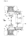
- Fig.4 shows a plan view of a transfer device at the front wheel side of the battery driven forklift, whereby the left front wheel 3a is driven by the first motor 16a, via a first axle 10a, while the right front wheel 3b is driven by the second motor, via a second axle 10b.
- the first axle 10a is formed in a transfer case 8a
- the second axle 10b is formed in a transfer case 8b.
- An end of a tension rod 11 is fastened to a connection member 13a that is fixed to the first axle 10a, while another end of the tension rod 11 is fastened to a connection member 13b that is fixed to the second axle 10b.
- An end of a tension rod 11 is fastened to a connection member 13a that is fixed to the first axle 10a, while another end of the tension rod 11 is fastened to a connection member 13b that is fixed to the second axle 10b.
- the patent reference 1 JP1996-216898 discloses a battery driven forklift in which a manual torque transmission device thereof is provided at the lowermost part of the forklift body and an electric power transmission system (an electric torque transmission device) including the parts such as an actuator and a motor is provided in the rear axles; thus, the space volume beneath the battery can be reduced; as a result, the battery can be located on the underside of the body; a battery of larger capacity (in comparison with conventional capacity) can be mounted; even in a case where a conventional battery is mounted, the height of the body can be reduced. Thus, many advantageous points are shown.
- the space 2C (see Fig.3 ) between a front end face 2b of the battery 2 and a rear side face of 6a of the mast is prone to be narrow, because of the size reduction requirements as to the vehicle (forklift) as well as the constraints as to the arrangements of the parts such as a tank for the battery hydraulic oil.
- a mast support portion i.e. members or parts
- the present disclosure aims at providing a transfer device for a battery driven forklift, whereby the mast support (i.e. members or parts) is easily formed regardless of the space limitation, by improving the arrangement of the power transmission system from the first and second motors to the front wheel driving parts (drive sections) of the first and second axles via a reduction gear device and a wet brake device.
- the mast support i.e. members or parts
- the present invention discloses a structure of a transfer device of a forklift, the device being provided with a tension rod which connects a first axle that drives a left front wheel by means of a first motor to a second axle that drives a right front wheel by means of a second motor, wherein the device is provided with:
- the transfer device is provided with:
- the whole configuration parts as to the wet brake device can be placed inside the reduction spur gear so as to covered with the gear.
- the space to house the wet brake device slips into the inner side space of the reduction spur gear (into the bowl shaped space inside the gear) just right.
- the structure of the transfer device can be of a smaller and more compact size.
- the whole configuration parts of the wet brake device is housed inside the reduction spur gear of a larger pitch circle in the spur reduction gear device that performs the first stage speed reduction, so that the wet brake device is covered with the reduction spur gear; further, the center of the input gear in the planetary reduction gear to perform the second stage speed reduction and the center of the reduction spur gear are coaxially aligned so that the both the centers are on the center line of the axle; and, the center of the output (side) carrier in the planetary reduction gear and the center of the reduction spur gear are coaxially aligned so that the both the centers are on the center line of the axle; moreover, the output (side) carrier is connected to the wheel hub as a front wheel drive part (section) of the axle.
- the spur reduction gear device that performs the first stage speed reduction and the planetary reduction gear to perform the second stage speed reduction are coupled without dead space. Therefore, the structure including the spur reduction gear device that performs the first stage speed reduction, the planetary reduction gear to perform the second stage speed reduction, and the wet brake device can be of a compact structure; further, the assembling of these devices can be simplified.
- the housing space for the structure including the spur reduction gear device that performs the first stage speed reduction, the planetary reduction gear to perform the second stage speed reduction, and the wet brake device can be reduced to a minimal space, so that the housing space is placed within the before-described space that is formed between the front end face of the battery and the rear side face of the mast.
- the mast support portion i.e. members or parts
- the mast support portion can be formed on or over the common center-line for the left and right front wheels, even in the case where the size reduction as to the vehicle is required, the constraints as to the arrangements of the parts such as a battery hydraulic oil tank for the battery are introduced, or the upsizing of the motors is required.
- Fig. 1 shows an outline perspective view of a transfer device of a battery driven forklift, in connection with an embodiment of the present invention
- Fig. 2 shows a longitudinal cross section (A-A cross section in Fig.1 ) of the transfer device.
- the numeral 90 denotes a transfer device and it is configured as follows.
- the left front wheel 3a is driven by the first motor 16a, via a first axle 10a
- the right front wheel 3b is driven by the second motor 16b, via a second axle 10b.
- the first axle 10a and the second axle 10b are formed in a left transfer case 8a and a right transfer case 8b respectively.
- a tension rod 11 is fastened to a crank structure 13 that is fixed to the first axle 10a, while another end of the tension rod 11 is fastened to a crank structure 13 that is fixed to the second axle 10b; and, the left and right axles 10a and 10b are connected each other via the tension rod 11.
- the numeral 12 denotes a turnbuckle for adjusting the length of the tension rod 11.
- the numeral 16S ( Fig. 1 ) denotes a center of the motor (hereby, the first motor); the numeral 9 denotes a center of the axle (hereby, the first axle 10a); the numeral 14 denotes a center of the tension rod 11.
- An output shaft 104 of the first motor 16a is fitted into a gear 105, with a self-centering fit 16S (see Fig. 2 ) between a hole that is provided in a transfer case 8a and an outer periphery (see Fig. 2 ) of the first motor.
- the gear 105 is engaged with an intermediate gear 106; the intermediate gear 106 is engaged with a reduction gear 107 (a reduction spur gear 107) of a larger pitch circle the cross section of which forms a shape of a large bowl cross section.
- a first stage speed reduction is performed.
- a plurality of bolts 141 fastens a brake hub 108 (a braking hub 108) of a wet brake device 150 to the reduction spur gear 107.
- a pin (not shown) fixes a relative position of the brake hub 108 against the transfer case 8a.
- a part of the outer periphery (a larger outer periphery part) of the brake hub 108 is supported by a bearing 113 retained by a brake cover 112 that is connected to the transfer case 8a by a plurality of bolt 111; a part of the outer periphery (a smaller outer periphery part) of the brake hub 108 is supported by a bearing 116 inserted into a retainer 115 that is fitted into the transfer case 8a, with a self-centering fit between the transfer case 8a and the retainer, and fastened to the transfer case 8a by a bolt 114.
- the hydraulic piston 117 is fitted into a hydraulic oil chamber 151 so as to perform reciprocating movements in the hydraulic oil chamber; when a hydraulic pressure is supplied into the hydraulic oil chamber 151, the elasticity (resilience) of a spring 119 is counteracted, and the hydraulic oil is released from the chamber 151 so that an exit plate included in a clutch disc assembly 130 is separated from a clutch disc included in the assembly 130; thus, the wet brake 150 comprising the assembly 130 is released.
- the wet brake device 150 acts as a negative parking brake.
- a piston 121 fitted into a hole engraved in the transfer case 8a acts as a service brake, the piston 121 receiving a hydraulic oil pressure.
- a crank structure 13 fastened to an end of the transfer device 8a, by means of a bolt 15 (see Fig. 2 as to the bolt 15); the tension rod 11 is fastened to a free end of the crank structure, by means of two nuts 17 (see Fig. 2 as to the nut 15).
- a (power transmission) input shaft 122 is connected to the inner periphery of the brake hub 108, with a spline coupling; on one side of the input shaft 122, a (power transmission) input gear 133 is formed as a part of the input shaft 122, whereby the input gear 133 transfers power to a planetary reduction gear 140 (a planet reduction gear 140).
- the planetary reduction gear 140 is an ordinary planetary reduction gear in which a carrier outputs power; and the planetary reduction gear 140 comprises a planetary gear 132 (an epicycle gear 132) that is rotation-freely supported by a planet gear pin 134, and a ring gear 127 that meshes with a planetary gear 132.
- An output (side) carrier 123 of the planetary reduction gear 140 transfers power to a wheel hub 124 that is connected to the output carrier 123 with a spline coupling; the wheel hub 124 drives the left front wheel 3a.
- the wheel hub 124 is rotation-freely supported, via a plurality of bearings 126, by a transfer case 125 that is fastened to the transfer case 8a by means of a plurality of bolts 125a.
- the structure of a transfer device for a forklift is disclosed.
- the transfer device is provided with:
- the whole configuration parts as to the wet brake device 150 can be placed inside the reduction spur gear 107 so as to covered with the gear 107.
- the space to house the wet brake device 150 slips into the inner side space of the reduction spur gear (into the bowl shaped space inside the gear 107) just right.
- the structure of the transfer device can be of a smaller and more compact size.
- the whole configuration parts of the wet brake device 150 is housed inside the reduction spur gear 107 of a larger pitch circle in the spur reduction gear device 160 that performs the first stage speed reduction, so that the wet brake device 150 is covered with the reduction spur gear 107; further, the center of the input gear 133 in the planetary reduction gear 140 to perform the second stage speed reduction and the center of the reduction spur gear 107 are coaxially aligned so that the both the centers are on the center line 9 of the axle; and, the center of the output (side) carrier 123 in the planetary reduction gear 140 and the center of the reduction spur gear 107 are coaxially aligned so that the both the centers are on the center line 9 of the axle; moreover, the output (side) carrier 123 is connected to the wheel hub 124 as a front wheel drive part (section) of the axle.
- the spur reduction gear device 160 that performs the first stage speed reduction and the planetary reduction gear 140 to perform the second stage speed reduction are coupled without dead space. Therefore, the structure including the spur reduction gear device 160 that performs the first stage speed reduction, the planetary reduction gear 140 to perform the second stage speed reduction, and the wet brake device 150 can be of a compact structure; further, the assembling of these devices can be simplified.
- the housing space for the structure including the spur reduction gear device 160 that performs the first stage speed reduction, the planetary reduction gear 140 to perform the second stage speed reduction, and the wet brake device 150 can be reduced to a minimal space, so that the housing space is placed within the before-described space 2C that is formed between the front end face 2b of the battery 2 and the rear side face 6a of the mast (see Fig. 3 ). Accordingly, the mast support portion (i.e.
- the present invention can supply a structure of a transfer device of a battery driven forklift, whereby the mast support portion is easily formed regardless of the space limitation, by improving the arrangement of the power transmission system from the first and second motors to the front wheel driving parts (drive section) of the first and second axles via a reduction gear device and a wet brake device.
Landscapes
- Engineering & Computer Science (AREA)
- Transportation (AREA)
- Mechanical Engineering (AREA)
- Structural Engineering (AREA)
- Chemical & Material Sciences (AREA)
- Combustion & Propulsion (AREA)
- Life Sciences & Earth Sciences (AREA)
- Geology (AREA)
- Civil Engineering (AREA)
- General Engineering & Computer Science (AREA)
- Arrangement Of Transmissions (AREA)
- Motor Power Transmission Devices (AREA)
- Braking Arrangements (AREA)
- Arrangement Or Mounting Of Propulsion Units For Vehicles (AREA)
Abstract
Structure of the transfer device of a forklift in which a mast support portion can be easily formed even in a limited space by improving the arrangement of a power transmission system extending from first and second motors to the front wheel drive section of first and second axles through a reduction gear and a wet braking device in a battery driven forklift. Furthermore, a wet braking device is provided inside the reduction spur gear coaxially thereto, the input gear of an planet reduction gear performing second gear reduction of the first and second motors is provided coaxially to the reduction spur gear while being coupled directly thereto, and the output carrier of the planet reduction gear is coupled with the left front wheel drive section of the first and second axles coaxially to the reduction spur gear.
Description
- This application relates to a structure of a transfer device of a battery driven forklift that is provided with a tension rod that connects a first axle with a second axle, whereby the first axle drives a left front wheel by use of a first motor and the second axle drives a right front wheel by use of a second motor.
-
Fig.3 shows an outline side view of a battery driven forklift, whereby thenumeral 100 denotes the forklift (the battery driven forklift); thenumeral 1 denotes a body of the forklift; thenumeral 6 denotes a mast; thenumeral 5 denotes a fork that lifts a load and performs up-and-down movements along the mast; thenumerals numerals numeral 2 denotes a battery. -
Fig.4 shows a plan view of a transfer device at the front wheel side of the battery driven forklift, whereby theleft front wheel 3a is driven by thefirst motor 16a, via afirst axle 10a, while the rightfront wheel 3b is driven by the second motor, via a second axle 10b.Thefirst axle 10a is formed in atransfer case 8a, while thesecond axle 10b is formed in atransfer case 8b. An end of atension rod 11 is fastened to aconnection member 13a that is fixed to thefirst axle 10a, while another end of thetension rod 11 is fastened to aconnection member 13b that is fixed to thesecond axle 10b. - An end of a
tension rod 11 is fastened to aconnection member 13a that is fixed to thefirst axle 10a, while another end of thetension rod 11 is fastened to aconnection member 13b that is fixed to thesecond axle 10b. - The patent reference 1 (
JP1996-216898 - In the battery driven forklift as depicted in
Figs. 3 and4 , thespace 2C (seeFig.3 ) between a front end face 2b of thebattery 2 and a rear side face of 6a of the mast is prone to be narrow, because of the size reduction requirements as to the vehicle (forklift) as well as the constraints as to the arrangements of the parts such as a tank for the battery hydraulic oil. - Accordingly, in upsizing the
first motor 16a and/or thesecond motor 16b, the location places of the first and/or second motors get closer to themast 6 in front of thespace 2C; thus, it becomes difficult that a mast support portion (i.e. members or parts) is formed on or over the common center-line for the left and right front wheels. - In view of the above-stated conventional technologies and anticipated solutions thereof, the present disclosure aims at providing a transfer device for a battery driven forklift, whereby the mast support (i.e. members or parts) is easily formed regardless of the space limitation, by improving the arrangement of the power transmission system from the first and second motors to the front wheel driving parts (drive sections) of the first and second axles via a reduction gear device and a wet brake device.
- In order to achieve the above objective, the present invention discloses a structure of a transfer device of a forklift, the device being provided with a tension rod which connects a first axle that drives a left front wheel by means of a first motor to a second axle that drives a right front wheel by means of a second motor, wherein the device is provided with:
- a spur reduction gear device between the first motor and a front wheel driving part of the first axle as well as between the second motor and a front wheel driving part of the second axle, whereby the spur reduction gear device performs the first stage reduction as to the speed of the first motor and the second motor;
- a reduction spur gear as an output side of the spur reduction gear device, whereby the center as to the reduction spur gear and the center as to the first or second axle are coaxially aligned;
- a wet brake device that is provided at the inner side of the reduction spur gear whereby the center of the wet brake device and the center of the reduction spur gear are coaxially aligned;
- a planetary reduction gear that performs the second stage reduction as to the speed of each one of the first and second motor;
- an input gear that is formed as a part of an input shaft through which power is inputted into the planetary reduction gear side from the spur reduction gear side, and to which the reduction spur gear is directly coupled, whereby the center of the input gear and the center of the reduction spur gear are coaxially aligned;
- an output side carrier (an output carrier) that forms the output shaft of the planetary reduction gear and is connected to a front wheel drive part (section) of each one of the first and second axle, whereby the center of the output carrier and the center of the reduction spur gear are coaxially aligned.
- Preferable embodiments are:
- (1) the structure of a transfer device of a forklift, thereby a brake hub of a wet brake device is provided so as to be coupled to the inner side of the reduction spur gear; whereby, the brake hub, a brake disc assembly, and the whole set of the driving parts as to the assembly are housed in the inner side of the reduction spur gear; and,
- (2) the structure of a transfer device of a forklift, thereby
the planetary reduction gear of the left or right side, and the front wheel driving part of the first or second axle are arranged in this order, respectively toward the left or right outside of the forklift longitudinal center plane, from the outer left or right side of the reduction spur gear, the outer left or right side corresponding to the output side of the left or right spur reduction gear device; and,
the brake hub, a brake disc assembly, and the whole set of the drive parts as to the assembly of each left or right side are arranged, on the right or left side of the reduction spur gear toward the inner side for the forklift longitudinal center plane, so that the brake hub, the brake disc assembly, and the whole set of the drive parts as to the assembly are housed inside the reduction spur gear. - According to the above-described present invention and the embodiments thereof, the transfer device is provided with:
- a spur reduction gear between the first motor (or the second motor) and the front wheel driving part (the front wheel drive section) i.e. the wheel hub , whereby the spur reduction gear (device) performs the first stage reduction as to the speed of the first motor;
- a reduction spur gear as an output side of the spur reduction gear (device) whereby the cross section of the reduction spur gear forms a shape of a large bowl cross section, and the center as to the gear and the center as to the axle are coaxially aligned;
- a wet brake device that is provided at the inner side of the reduction spur gear (inside the bowl shape space) whereby the center of the wet brake device and the center of the reduction spur gear are coaxially aligned;
- a planetary reduction gear that performs the second stage reduction as to the speed of the motor;
- an input gear that is formed as a part of the input shaft through which power is inputted into the planetary reduction gear side, and to which the reduction spur gear is directly coupled, whereby the center of the input gear and the center of the reduction spur gear are coaxially aligned;
- an output (side) carrier that forms the output shaft of the planetary reduction gear and is connected to a wheel hub as a front wheel drive part (section) of the axle, whereby the center of the output carrier and the center of the reduction spur gear are coaxially aligned; more in detail,
- a brake hub of the wet brake device is provided so as to be coupled to the inner side (inside of the bowl shaped space) of the reduction spur gear, whereby the brake hub, the brake disc assembly, and the whole set of the drive parts as to the assembly are housed in the inner side of the reduction spur gear so as to be covered with the gear.
- Accordingly, in the manner that the brake hub, the brake disc assembly, and the whole set of the drive parts as to the assembly are housed in the inner side of the reduction spur gear of a larger pitch circle, the whole configuration parts as to the wet brake device can be placed inside the reduction spur gear so as to covered with the gear. Thus, the space to house the wet brake device slips into the inner side space of the reduction spur gear (into the bowl shaped space inside the gear) just right. As a result, the structure of the transfer device can be of a smaller and more compact size.
- Further, in the embodiment as described above, the whole configuration parts of the wet brake device is housed inside the reduction spur gear of a larger pitch circle in the spur reduction gear device that performs the first stage speed reduction, so that the wet brake device is covered with the reduction spur gear; further, the center of the input gear in the planetary reduction gear to perform the second stage speed reduction and the center of the reduction spur gear are coaxially aligned so that the both the centers are on the center line of the axle; and, the center of the output (side) carrier in the planetary reduction gear and the center of the reduction spur gear are coaxially aligned so that the both the centers are on the center line of the axle; moreover, the output (side) carrier is connected to the wheel hub as a front wheel drive part (section) of the axle. Thus, the spur reduction gear device that performs the first stage speed reduction and the planetary reduction gear to perform the second stage speed reduction are coupled without dead space. Therefore, the structure including the spur reduction gear device that performs the first stage speed reduction, the planetary reduction gear to perform the second stage speed reduction, and the wet brake device can be of a compact structure; further, the assembling of these devices can be simplified.
- Further, the housing space for the structure including the spur reduction gear device that performs the first stage speed reduction, the planetary reduction gear to perform the second stage speed reduction, and the wet brake device can be reduced to a minimal space, so that the housing space is placed within the before-described space that is formed between the front end face of the battery and the rear side face of the mast. Accordingly, the mast support portion (i.e. members or parts) can be formed on or over the common center-line for the left and right front wheels, even in the case where the size reduction as to the vehicle is required, the constraints as to the arrangements of the parts such as a battery hydraulic oil tank for the battery are introduced, or the upsizing of the motors is required.
- The present invention will now be described in greater detail with reference to the preferred embodiments of the invention and the accompanying drawings, wherein:
-
Fig. 1 shows an outline perspective view (an outline bird's eye view) of a transfer device of a battery driven forklift, according to an embodiment of the present invention; -
Fig. 2 shows a longitudinal cross section (A-A cross section inFig.1 ) of the transfer device; -
Fig. 3 shows an outline side view of a battery driven forklift; -
Fig. 4 shows a plan view of a transfer device at the front wheel side of the battery driven forklift. - Hereafter, the present invention will be described in detail with reference to the embodiments shown in the figures. However, the dimensions, materials, shape, the relative placement and so on of a component described in these embodiments shall not be construed as limiting the scope of the invention thereto, unless especially specific mention is made.
-
Fig. 1 shows an outline perspective view of a transfer device of a battery driven forklift, in connection with an embodiment of the present invention;
Fig. 2 shows a longitudinal cross section (A-A cross section inFig.1 ) of the transfer device. - In
Fig. 1 , thenumeral 90 denotes a transfer device and it is configured as follows. - As is the case in the transfer device in
Fig. 4 , in thetransfer device 90 inFig. 1 , theleft front wheel 3a is driven by thefirst motor 16a, via afirst axle 10a, while the rightfront wheel 3b is driven by thesecond motor 16b, via asecond axle 10b. Thefirst axle 10a and thesecond axle 10b are formed in aleft transfer case 8a and aright transfer case 8b respectively. - Further, an end of a
tension rod 11 is fastened to acrank structure 13 that is fixed to thefirst axle 10a, while another end of thetension rod 11 is fastened to acrank structure 13 that is fixed to thesecond axle 10b; and, the left andright axles tension rod 11. Thenumeral 12 denotes a turnbuckle for adjusting the length of thetension rod 11. - The
numeral 16S (Fig. 1 ) denotes a center of the motor (hereby, the first motor); thenumeral 9 denotes a center of the axle (hereby, thefirst axle 10a); thenumeral 14 denotes a center of thetension rod 11. - In the next place, according to
Fig. 2 , the power transmission system of the transfer device now will be explained. The following explanation is made in connection to the left side (thefirst axle 10a side); a similar explanation holds in connection to the right side (thesecond axle 10b side). - An
output shaft 104 of thefirst motor 16a is fitted into agear 105, with a self-centering fit 16S (seeFig. 2 ) between a hole that is provided in atransfer case 8a and an outer periphery (seeFig. 2 ) of the first motor. Thegear 105 is engaged with anintermediate gear 106; theintermediate gear 106 is engaged with a reduction gear 107 (a reduction spur gear 107) of a larger pitch circle the cross section of which forms a shape of a large bowl cross section. Thus, a first stage speed reduction is performed. - Inside of the reduction spur
gear 107, a plurality ofbolts 141 fastens a brake hub 108 (a braking hub 108) of awet brake device 150 to thereduction spur gear 107. A pin (not shown) fixes a relative position of thebrake hub 108 against thetransfer case 8a. - A part of the outer periphery (a larger outer periphery part) of the
brake hub 108 is supported by abearing 113 retained by abrake cover 112 that is connected to thetransfer case 8a by a plurality ofbolt 111; a part of the outer periphery (a smaller outer periphery part) of thebrake hub 108 is supported by abearing 116 inserted into aretainer 115 that is fitted into thetransfer case 8a, with a self-centering fit between thetransfer case 8a and the retainer, and fastened to thetransfer case 8a by abolt 114. - The
hydraulic piston 117 is fitted into ahydraulic oil chamber 151 so as to perform reciprocating movements in the hydraulic oil chamber; when a hydraulic pressure is supplied into thehydraulic oil chamber 151, the elasticity (resilience) of aspring 119 is counteracted, and the hydraulic oil is released from thechamber 151 so that an exit plate included in aclutch disc assembly 130 is separated from a clutch disc included in theassembly 130; thus, thewet brake 150 comprising theassembly 130 is released. In other words, thewet brake device 150 acts as a negative parking brake. - Moreover, a
piston 121 fitted into a hole engraved in thetransfer case 8a acts as a service brake, thepiston 121 receiving a hydraulic oil pressure. - Further, in
Fig. 1 , acrank structure 13 fastened to an end of thetransfer device 8a, by means of a bolt 15 (seeFig. 2 as to the bolt 15); thetension rod 11 is fastened to a free end of the crank structure, by means of two nuts 17 (seeFig. 2 as to the nut 15). There is an eccentricity T1 between a center 15t of thebolt 15 and acenter 15s of the support part for thecrank structure 13; and, in this manner, the locking of thebolt 15 is securely performed. - On the other hand, a (power transmission)
input shaft 122 is connected to the inner periphery of thebrake hub 108, with a spline coupling; on one side of theinput shaft 122, a (power transmission)input gear 133 is formed as a part of theinput shaft 122, whereby theinput gear 133 transfers power to a planetary reduction gear 140 (a planet reduction gear 140). Theplanetary reduction gear 140 is an ordinary planetary reduction gear in which a carrier outputs power; and theplanetary reduction gear 140 comprises a planetary gear 132 (an epicycle gear 132) that is rotation-freely supported by aplanet gear pin 134, and aring gear 127 that meshes with aplanetary gear 132. - An output (side)
carrier 123 of theplanetary reduction gear 140 transfers power to awheel hub 124 that is connected to theoutput carrier 123 with a spline coupling; thewheel hub 124 drives the leftfront wheel 3a. - The
wheel hub 124 is rotation-freely supported, via a plurality ofbearings 126, by atransfer case 125 that is fastened to thetransfer case 8a by means of a plurality ofbolts 125a. - According to the above-described embodiments, the structure of a transfer device for a forklift is disclosed. The transfer device is provided with:
- a spur
reduction gear device 160 between thefirst motor 16a and a front wheel driving part of thefirst axle 10a as well as between thesecond motor 16b and a front wheel driving part of thesecond axle 10b, whereby the spurreduction gear device 160 performs the first stage reduction as to the speed of the first motor and the second motor; - a
reduction spur gear 107 as an output side of the spurreduction gear device 160, whereby the center as to the reduction spur gear and the center as to the first or second axle are coaxially aligned; - a
wet brake device 150 that is provided at the inner side of the reduction spur gear whereby the center of thewet brake device 150 and the center of thereduction spur gear 107 are coaxially aligned; - a
planetary reduction gear 140 that performs the second stage reduction as to the speed of each one of thefirst motor 16a and thesecond motor 16b; - an
input gear 133 that is formed as a part of aninput shaft 122 through which power is inputted into the planetary reduction gear side from the spur reduction gear side, and to which thereduction spur gear 107 is directly coupled, whereby the center of theinput gear 133 and the center of thereduction spur gear 107 are coaxially aligned; - an
output side carrier 123 that forms the output shaft of theplanetary reduction gear 140 and is connected to thewheel hub 124, namely, a front wheel drive part of each one of the first and second axle, whereby the center of theoutput carrier 123 and the center of thereduction spur gear 107 are coaxially aligned; more in detail, - a
brake hub 108 of thewet brake device 150 is provided so as to be coupled to the inner side (inside of the bowl shaped space) of thereduction spur gear 107, whereby thebrake hub 108, the brake disc assembly, and the whole set of the drive parts as to the assembly are housed in the inner side of thereduction spur gear 107 so as to be covered with thegear 107. - Accordingly, in the manner that the
brake hub 108, the brake disc assembly, and the whole set of the drive parts as to the assembly are housed so as to be covered in the inner side of thereduction spur gear 107 of a larger pitch circle, the whole configuration parts as to thewet brake device 150 can be placed inside thereduction spur gear 107 so as to covered with thegear 107. Thus, the space to house thewet brake device 150 slips into the inner side space of the reduction spur gear (into the bowl shaped space inside the gear 107) just right. As a result, the structure of the transfer device can be of a smaller and more compact size. - Further, in the embodiment as described above, the whole configuration parts of the
wet brake device 150 is housed inside thereduction spur gear 107 of a larger pitch circle in the spurreduction gear device 160 that performs the first stage speed reduction, so that thewet brake device 150 is covered with thereduction spur gear 107; further, the center of theinput gear 133 in theplanetary reduction gear 140 to perform the second stage speed reduction and the center of thereduction spur gear 107 are coaxially aligned so that the both the centers are on thecenter line 9 of the axle; and, the center of the output (side)carrier 123 in theplanetary reduction gear 140 and the center of thereduction spur gear 107 are coaxially aligned so that the both the centers are on thecenter line 9 of the axle; moreover, the output (side)carrier 123 is connected to thewheel hub 124 as a front wheel drive part (section) of the axle. Thus, the spurreduction gear device 160 that performs the first stage speed reduction and theplanetary reduction gear 140 to perform the second stage speed reduction are coupled without dead space. Therefore, the structure including the spurreduction gear device 160 that performs the first stage speed reduction, theplanetary reduction gear 140 to perform the second stage speed reduction, and thewet brake device 150 can be of a compact structure; further, the assembling of these devices can be simplified. - Further, the housing space for the structure including the spur
reduction gear device 160 that performs the first stage speed reduction, theplanetary reduction gear 140 to perform the second stage speed reduction, and thewet brake device 150 can be reduced to a minimal space, so that the housing space is placed within the before-describedspace 2C that is formed between the front end face 2b of thebattery 2 and therear side face 6a of the mast (seeFig. 3 ). Accordingly, the mast support portion (i.e. members or parts) can be formed on or over the common center-line for the left and right front wheels, even in the case where the size reduction as to the vehicle is required, the constraints as to the arrangements of the parts such as a battery hydraulic oil tank for thebattery 2 are introduced, or the upsizing of the motorsl6a and 16b is required. - The present invention can supply a structure of a transfer device of a battery driven forklift, whereby the mast support portion is easily formed regardless of the space limitation, by improving the arrangement of the power transmission system from the first and second motors to the front wheel driving parts (drive section) of the first and second axles via a reduction gear device and a wet brake device.
Claims (3)
- A structure of a transfer device of a forklift, the device being provided with a tension rod which connects a first axle that drives a left front wheel by means of a first motor to a second axle that drives a right front wheel by means of a second motor, wherein the device comprises:a spur reduction gear device between the first motor and a front wheel driving part of the first axle as well as between the second motor and a front wheel driving part of the second axle, whereby the spur reduction gear device performs the first stage reduction as to the speed of the first motor and the second motor;a reduction spur gear as an output side of the spur reduction gear device, whereby the center as to the reduction spur gear and the center as to the first or second axle are coaxially aligned;a wet brake device that is provided at the inner side of the reduction spur gear whereby the center of the wet brake device and the center of the reduction spur gear are coaxially aligned;a planetary reduction gear that performs the second stage reduction as to the speed of each one of the first motor and the second motor;an input gear that is formed as a part of an input shaft through which power is inputted into the planetary reduction gear side from the spur reduction gear side, and to which the reduction spur gear is directly coupled, whereby the center of the input gear and the center of the reduction spur gear are coaxially aligned;an output side carrier that forms the output shaft of the planetary reduction gear and is connected to a front wheel drive part of each one of the first axle and the second axle, whereby the center of the output carrier and the center of the reduction spur gear are coaxially aligned.
- The structure of a transfer device of a forklift according to claim 1, thereby a brake hub of a wet brake device is provided so as to be coupled to the inner side of the reduction spur gear; whereby, the brake hub, a brake disc assembly, and the whole set of the driving parts as to the assembly are housed in the inner side of the reduction spur gear.
- The structure of a transfer device of a forklift according to claim 1, thereby
the planetary reduction gear of the left or right side, and the front wheel driving part of the first or second axle are arranged in this order, respectively toward the left or right outside of the forklift longitudinal center plane, from the outer left or right side of the reduction spur gear , the outer left or right side corresponding to the output side of the left or right spur reduction gear device; and,
the brake hub, a brake disc assembly, and the whole set of the drive parts as to the assembly of each left or right side are arranged, on the right or left side of the reduction spur gear toward the inner side for the forklift longitudinal center plane, so that the brake hub, the brake disc assembly, and the whole set of the drive parts as to the assembly of each left or right side are housed inside each reduction spur gear.
Applications Claiming Priority (2)
| Application Number | Priority Date | Filing Date | Title |
|---|---|---|---|
| JP2007259376A JP2009083796A (en) | 2007-10-03 | 2007-10-03 | Structure of transfer device for fork lift |
| PCT/JP2008/066017 WO2009044603A1 (en) | 2007-10-03 | 2008-08-29 | Structure of transfer device of forklift |
Publications (1)
| Publication Number | Publication Date |
|---|---|
| EP2127934A1 true EP2127934A1 (en) | 2009-12-02 |
Family
ID=40526032
Family Applications (1)
| Application Number | Title | Priority Date | Filing Date |
|---|---|---|---|
| EP08835583A Withdrawn EP2127934A1 (en) | 2007-10-03 | 2008-08-29 | Structure of transfer device of forklift |
Country Status (3)
| Country | Link |
|---|---|
| EP (1) | EP2127934A1 (en) |
| JP (1) | JP2009083796A (en) |
| WO (1) | WO2009044603A1 (en) |
Cited By (9)
| Publication number | Priority date | Publication date | Assignee | Title |
|---|---|---|---|---|
| JP2013087824A (en) * | 2011-10-14 | 2013-05-13 | Sumitomo Heavy Ind Ltd | Wheel driving speed reducer |
| CN103427513A (en) * | 2012-05-21 | 2013-12-04 | 林德材料处理有限责任公司 | Ground conveyor with electric drive motor |
| CN103427514A (en) * | 2012-05-21 | 2013-12-04 | 林德材料处理有限责任公司 | Ground conveyor with electric pump motor |
| US8863906B2 (en) | 2000-12-08 | 2014-10-21 | Kone Corporation | Elevator and traction sheave of an elevator |
| CN105034797A (en) * | 2015-08-06 | 2015-11-11 | 安徽合力股份有限公司 | Rear wheel drive electric forklift provided with wet-type braking front axles |
| EP3566891A1 (en) * | 2018-05-08 | 2019-11-13 | Dana (Wuxi) Technology Co. Ltd. | Multi-stage planetary reduction drive apparatus for vehicle and mounting arrangement thereof |
| US20210362590A1 (en) * | 2018-07-04 | 2021-11-25 | Byd Company Limited | Vehicle transmission apparatus and vehicle |
| CN116085397A (en) * | 2021-11-08 | 2023-05-09 | 金华智升机械有限公司 | A clutch device for an electric forklift |
| US12502954B2 (en) | 2022-12-01 | 2025-12-23 | Dana Italia S.R.L. | Systems for a driveline |
Families Citing this family (4)
| Publication number | Priority date | Publication date | Assignee | Title |
|---|---|---|---|---|
| JP6141085B2 (en) * | 2013-04-19 | 2017-06-07 | 株式会社クボタ | Harvesting machine |
| CN105208850B (en) * | 2013-04-08 | 2019-01-04 | 株式会社久保田 | Harvesters and work machines |
| CN104228559B (en) * | 2014-04-14 | 2016-11-02 | 第一拖拉机股份有限公司 | The Tractor Power Train of spatial triaxial 48F+48R band creeper gear |
| DE102017123264B3 (en) * | 2017-10-06 | 2018-12-27 | Schaeffler Technologies AG & Co. KG | Electromechanical drive device for a multi-track motor vehicle |
Family Cites Families (4)
| Publication number | Priority date | Publication date | Assignee | Title |
|---|---|---|---|---|
| JPH08216898A (en) | 1995-02-17 | 1996-08-27 | Nippon Yusoki Co Ltd | Forklift steering mechanism |
| JP2002061108A (en) * | 2000-08-24 | 2002-02-28 | Sakai Heavy Ind Ltd | Tire roller |
| JP4551637B2 (en) * | 2003-07-11 | 2010-09-29 | Tcm株式会社 | Vehicle drive device |
| JP2005263140A (en) * | 2004-03-22 | 2005-09-29 | Mitsubishi Heavy Ind Ltd | Driving device for vehicle |
-
2007
- 2007-10-03 JP JP2007259376A patent/JP2009083796A/en not_active Withdrawn
-
2008
- 2008-08-29 EP EP08835583A patent/EP2127934A1/en not_active Withdrawn
- 2008-08-29 WO PCT/JP2008/066017 patent/WO2009044603A1/en not_active Ceased
Non-Patent Citations (1)
| Title |
|---|
| See references of WO2009044603A1 * |
Cited By (14)
| Publication number | Priority date | Publication date | Assignee | Title |
|---|---|---|---|---|
| US8863906B2 (en) | 2000-12-08 | 2014-10-21 | Kone Corporation | Elevator and traction sheave of an elevator |
| JP2013087824A (en) * | 2011-10-14 | 2013-05-13 | Sumitomo Heavy Ind Ltd | Wheel driving speed reducer |
| CN103427513A (en) * | 2012-05-21 | 2013-12-04 | 林德材料处理有限责任公司 | Ground conveyor with electric drive motor |
| CN103427514A (en) * | 2012-05-21 | 2013-12-04 | 林德材料处理有限责任公司 | Ground conveyor with electric pump motor |
| EP2667505A3 (en) * | 2012-05-21 | 2017-05-03 | Linde Material Handling GmbH | Industrial truck with an electric drive motor |
| CN105034797A (en) * | 2015-08-06 | 2015-11-11 | 安徽合力股份有限公司 | Rear wheel drive electric forklift provided with wet-type braking front axles |
| EP3566891A1 (en) * | 2018-05-08 | 2019-11-13 | Dana (Wuxi) Technology Co. Ltd. | Multi-stage planetary reduction drive apparatus for vehicle and mounting arrangement thereof |
| CN110454550A (en) * | 2018-05-08 | 2019-11-15 | 德纳(无锡)技术有限公司 | Multi-stage planetary reduction transmission device and mounting structure for vehicle |
| US10953745B2 (en) | 2018-05-08 | 2021-03-23 | Dana (WUXI) Technology Co., Ltd. | Multi-stage planetary reduction drive apparatus for vehicle and mounting arrangement thereof |
| CN110454550B (en) * | 2018-05-08 | 2022-02-01 | 德纳(无锡)技术有限公司 | Multistage planetary reduction transmission and mounting structure for vehicle |
| US20210362590A1 (en) * | 2018-07-04 | 2021-11-25 | Byd Company Limited | Vehicle transmission apparatus and vehicle |
| US11827091B2 (en) * | 2018-07-04 | 2023-11-28 | Byd Company Limited | Vehicle transmission apparatus and vehicle |
| CN116085397A (en) * | 2021-11-08 | 2023-05-09 | 金华智升机械有限公司 | A clutch device for an electric forklift |
| US12502954B2 (en) | 2022-12-01 | 2025-12-23 | Dana Italia S.R.L. | Systems for a driveline |
Also Published As
| Publication number | Publication date |
|---|---|
| JP2009083796A (en) | 2009-04-23 |
| WO2009044603A1 (en) | 2009-04-09 |
Similar Documents
| Publication | Publication Date | Title |
|---|---|---|
| JP2009083796A (en) | Structure of transfer device for fork lift | |
| US7115057B2 (en) | Drive axle assembly for hybrid electric vehicle | |
| US9550414B2 (en) | Traveling drive device for dump truck | |
| US6910987B2 (en) | Automatic transmission for light vehicles employing V-Twin engines | |
| US20170082159A1 (en) | Electronic disc brake | |
| CN100484795C (en) | Walking and braking device for loader | |
| JP2005231564A (en) | Electric wheel drive device | |
| CN103119319A (en) | Sub-assembly for an electromechanical brake actuator | |
| KR102582455B1 (en) | Electronic disc brake | |
| CA2298112A1 (en) | Hydrostatic transaxle having axial piston motor and method for manufacturing transaxles | |
| US11808331B2 (en) | Transmission assembly | |
| US20060240931A1 (en) | Differential for an electrically powered driving axle | |
| HUT71877A (en) | Basic unit for a motor vehicle | |
| CN117325591A (en) | Wet-type driving axle | |
| CN100522678C (en) | A transmission for hybrid vehicles | |
| US20210332871A1 (en) | Gear driving device for automotive movable parts | |
| EP4075023B1 (en) | A transmission arrangement | |
| KR20200114711A (en) | Actuator for electric parking brake | |
| KR20140015637A (en) | Two-stage electric axle apparatus for forward and backward driving | |
| EP4257850A1 (en) | Axle assembly having a differential brake | |
| CN201040523Y (en) | Walking and braking device for loader | |
| CN110657177A (en) | Motor-driven vehicle brake power driving device | |
| CN219312490U (en) | Electric drive axle structure of vehicle | |
| CN100516590C (en) | Gear box with built-in braking system | |
| WO2024197965A1 (en) | Dual-purpose transport vehicle |
Legal Events
| Date | Code | Title | Description |
|---|---|---|---|
| PUAI | Public reference made under article 153(3) epc to a published international application that has entered the european phase |
Free format text: ORIGINAL CODE: 0009012 |
|
| 17P | Request for examination filed |
Effective date: 20091008 |
|
| AK | Designated contracting states |
Kind code of ref document: A1 Designated state(s): AT BE BG CH CY CZ DE DK EE ES FI FR GB GR HR HU IE IS IT LI LT LU LV MC MT NL NO PL PT RO SE SI SK TR |
|
| STAA | Information on the status of an ep patent application or granted ep patent |
Free format text: STATUS: THE APPLICATION HAS BEEN WITHDRAWN |
|
| 18W | Application withdrawn |
Effective date: 20100409 |