EP2127830B1 - Planer - Google Patents
Planer Download PDFInfo
- Publication number
- EP2127830B1 EP2127830B1 EP09160529.5A EP09160529A EP2127830B1 EP 2127830 B1 EP2127830 B1 EP 2127830B1 EP 09160529 A EP09160529 A EP 09160529A EP 2127830 B1 EP2127830 B1 EP 2127830B1
- Authority
- EP
- European Patent Office
- Prior art keywords
- housing
- shaft
- planer
- hand held
- electrically powered
- Prior art date
- Legal status (The legal status is an assumption and is not a legal conclusion. Google has not performed a legal analysis and makes no representation as to the accuracy of the status listed.)
- Not-in-force
Links
- 238000005452 bending Methods 0.000 description 1
- 238000013016 damping Methods 0.000 description 1
Images



Classifications
-
- B—PERFORMING OPERATIONS; TRANSPORTING
- B27—WORKING OR PRESERVING WOOD OR SIMILAR MATERIAL; NAILING OR STAPLING MACHINES IN GENERAL
- B27C—PLANING, DRILLING, MILLING, TURNING OR UNIVERSAL MACHINES FOR WOOD OR SIMILAR MATERIAL
- B27C1/00—Machines for producing flat surfaces, e.g. by rotary cutters; Equipment therefor
- B27C1/10—Hand planes equipped with power-driven cutter blocks
-
- B—PERFORMING OPERATIONS; TRANSPORTING
- B25—HAND TOOLS; PORTABLE POWER-DRIVEN TOOLS; MANIPULATORS
- B25F—COMBINATION OR MULTI-PURPOSE TOOLS NOT OTHERWISE PROVIDED FOR; DETAILS OR COMPONENTS OF PORTABLE POWER-DRIVEN TOOLS NOT PARTICULARLY RELATED TO THE OPERATIONS PERFORMED AND NOT OTHERWISE PROVIDED FOR
- B25F5/00—Details or components of portable power-driven tools not particularly related to the operations performed and not otherwise provided for
- B25F5/006—Vibration damping means
-
- H—ELECTRICITY
- H02—GENERATION; CONVERSION OR DISTRIBUTION OF ELECTRIC POWER
- H02K—DYNAMO-ELECTRIC MACHINES
- H02K1/00—Details of the magnetic circuit
- H02K1/06—Details of the magnetic circuit characterised by the shape, form or construction
- H02K1/12—Stationary parts of the magnetic circuit
- H02K1/14—Stator cores with salient poles
- H02K1/145—Stator cores with salient poles having an annular coil, e.g. of the claw-pole type
Definitions
- FIG. 1 A known type of hand held planer for removing the surface of a workpiece such as a wooden door is shown in Figure 1 .
- the planer 2 has a housing 4 having a rear handle 6, provided with a trigger switch 8 for supplying electrical power via a power supply cable 10 to an electric motor 12, and a front handle 14.
- a shoe 16 having a part-cylindrical recess 19 is mounted to and flush with the bottom 20 of the housing 4.
- a planer cylinder 22 having a pair of diametrically opposed blades 24 is rotatably mounted in a recess 19 so that the surface of the planer cylinder 22 protrudes slightly from the recess 19 through an aperture 18 in the underside of the shoe 16 in order to engage a workpiece (not shown) when the planer 2 rests on the workpiece.
- the motor 12 has an output shaft 26 which is connected via a drive belt 28 to the planer cylinder 22 such that the planer cylinder 22 is driven at lower rotational speed and higher torque than the output shaft 26 of the motor 12.
- GB2299051 and EP1428620 disclose such a hand held planer.
- DE3600882 (disclosing the preamble of claim 1), EP0878280 , WO93/15885 , US4693648 and US4555850 disclose planers having a rear handle comprising an elongate shaft attached at one end to the rear of the housing. However, these patents disclose planers having a separate front handle mounted directly onto the front of the housing.
- the present invention seeks to provide an improved design for the rear and front handles of a hand held planer.
- the shaft can be resiliently mounted on the housing to allow the grip and the front handle to move against a biasing force towards or away from the housing. By constructing it in this manner, vibration damping can be provided for both of the front and rear handles.
- At least a part of the shaft can be resilient to allow the grip and/or front handle to move against a biasing force towards of away from the housing. Dependant on which part of the shaft is resistant, vibration dampening can be provided for just the front handle or both handles.
- the hand held electrically power planer comprises a housing 300. Attached to the underside of the housing 300 is a work piece engaging shoe 302 through which is formed an aperture 304. The shoe 302 rests against a work piece when the planer is in use.
- a cutting drum (indicated by dashed lines 306 in Figure 6 ). A part 308 of drum 306 protrudes through the aperture 304 in the shoe 302. A cutting blade 318 is rigidly attached to the drum 306.
- An electric motor (indicated by dashed lines 310 in Figure 16) is mounted within the housing 300.
- the motor 310 rotatingly drives the cutting drum 306 via a rubber belt (shown by dashed lines 312 in Figure 6 ) when activated in a similar manner to the planer described previously with reference to Figure 1 .
- the motor is powered by a battery pack 316 releasably mounted on to the rear 314 of the housing 300.
- the battery 316 is in electrical contact with the motor 310 via a trigger switch 317. Depression of the trigger switch 317 provides an electrical connection between the battery 316 and the motor 310 and thereby activates the motor 310 which in turn rotatingly drives the cutting drum 306 in well known manner.
- a knob 320 is slideably mounted on the front of the housing 300. Movement of the knob 320 results in the adjustment of the height of the front of the shoe 302, forward of the aperture 304, relative to the housing.
- the rear handle comprises an elongate shaft 322 which is attached at one end to the rear part 314 of the housing 300.
- the shaft 322 extends in a forward direction, along the length of the housing 300, over the top of the housing 300 as best seen in Figure 6 .
- a grip 324 is mounted on the shaft 322 by which an operator grasps the shaft 322.
- the grip 324 is ideally moulded to the shape of the hand of an operator for comfort. Alternatively, the grip could be integrally formed with the shaft 322.
- the front handle 326 is integrally formed on the free end shaft 322.
- the trigger switch 317 is also mounted on the underside of the shaft 322.
- the shaft 322 is constructed so that it can flex towards the housing 300 (Arrow A) or away from the housing (Arrow B) when pressure is applied to the shaft 322.
- the flexibility is generated by making the part 328 of the shaft 322 that connects to the rear 314 of the housing 300 resilient, allowing the shaft 322 to bend at this point 328. It will be appreciated that the whole of the shaft could be made in a resilient manner to allow bending any where along its length.
- the operator would grasp the shaft 322 via the grip 324 with one hand and the front handle 326 with the other hand in order to use the planer.
- the operation of the planer is the same as that of a conventional planer, the operator squeezing the trigger switch 317 to switch it on.
- the pressure on the shaft 322 will cause it to flex moving the grip 324 and the front handle 326 towards the housing 300 slightly.
- the cutting action of the blade 318 generates vibration in the housing 300.
- the shaft 322 being connect to the housing 300 with a resilient part 328, the amount of vibration transmitted to the shaft 322 from the housing is reduced, the resilient part 328 acting as a vibration dampener.
- the shaft 322 in the second embodiment of the rear handle is rigid along the whole of its length, however, the shaft 322 is attached to the rear 314 of the housing 300 via a pivot 330. This enables the shaft 322, grip 324 and front handle 326 to pivot towards or away from the housing 300.
- a helical spring 332 is connected between the shaft 322 and rear 314 of the housing and resiliently biases the shaft to a predetermined position as shown in Figure 7 .
- the spring 332 provides a biasing force against the movement of the shaft 322 towards or away from the housing 300.
- the spring also acts as a vibration dampener, reducing the amount of vibration transferred from the housing 300 to the shaft 322.
Landscapes
- Engineering & Computer Science (AREA)
- Life Sciences & Earth Sciences (AREA)
- Mechanical Engineering (AREA)
- Wood Science & Technology (AREA)
- Forests & Forestry (AREA)
- Power Engineering (AREA)
- Milling, Drilling, And Turning Of Wood (AREA)
Description
- A known type of hand held planer for removing the surface of a workpiece such as a wooden door is shown in
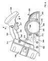
Figure 1 . Theplaner 2 has ahousing 4 having arear handle 6, provided with atrigger switch 8 for supplying electrical power via apower supply cable 10 to anelectric motor 12, and afront handle 14. Ashoe 16 having a part-cylindrical recess 19 is mounted to and flush with thebottom 20 of thehousing 4. Aplaner cylinder 22 having a pair of diametricallyopposed blades 24 is rotatably mounted in arecess 19 so that the surface of theplaner cylinder 22 protrudes slightly from therecess 19 through anaperture 18 in the underside of theshoe 16 in order to engage a workpiece (not shown) when theplaner 2 rests on the workpiece. Themotor 12 has anoutput shaft 26 which is connected via adrive belt 28 to theplaner cylinder 22 such that theplaner cylinder 22 is driven at lower rotational speed and higher torque than theoutput shaft 26 of themotor 12. When theplaner cylinder 22 is driven by themotor 12 via thebelt 28, theblades 22 contact and remove material from the surface of the work piece. -
GB2299051 EP1428620 disclose such a hand held planer. -
DE3600882 (disclosing the preamble of claim 1),EP0878280 ,WO93/15885 US4693648 andUS4555850 disclose planers having a rear handle comprising an elongate shaft attached at one end to the rear of the housing. However, these patents disclose planers having a separate front handle mounted directly onto the front of the housing. - The present invention seeks to provide an improved design for the rear and front handles of a hand held planer.
- Accordingly, there is provided a hand held electrically powered planer according to claim 1.
- The shaft can be resiliently mounted on the housing to allow the grip and the front handle to move against a biasing force towards or away from the housing. By constructing it in this manner, vibration damping can be provided for both of the front and rear handles.
- Alternatively, at least a part of the shaft can be resilient to allow the grip and/or front handle to move against a biasing force towards of away from the housing. Dependant on which part of the shaft is resistant, vibration dampening can be provided for just the front handle or both handles.
- Two preferred embodiments of the invention will now be described, by way of example only and not in any limitative sense, with reference to the accompanying drawings in which:-
-
Figure 1 is a cross sectional elevational view of a known hand held power planer; -
Figure 2 is a cross section elevation view of another design of battery powered planer; -
Figure 3 shows a perspective view of a planer according to the first embodiment of the present invention; -
Figure 4 shows a top view of the planer according to the first embodiment of the present invention; -
Figure 5 shows an underside view of the planer according to the first embodiment of the present invention; -
Figure 6 shows a side view of the planer according to the first embodiment of the present invention; and -
Figure 7 shows a side view of the planer according to the second embodiment of the present invention. - Referring to
Figures 3 to 6 , the hand held electrically power planer comprises ahousing 300. Attached to the underside of thehousing 300 is a workpiece engaging shoe 302 through which is formed anaperture 304. Theshoe 302 rests against a work piece when the planer is in use. Rotatably mounted within thehousing 300 is a cutting drum (indicated bydashed lines 306 inFigure 6 ). Apart 308 ofdrum 306 protrudes through theaperture 304 in theshoe 302. Acutting blade 318 is rigidly attached to thedrum 306. An electric motor (indicated bydashed lines 310 in Figure 16) is mounted within thehousing 300. Themotor 310 rotatingly drives thecutting drum 306 via a rubber belt (shown bydashed lines 312 inFigure 6 ) when activated in a similar manner to the planer described previously with reference toFigure 1 . The motor is powered by abattery pack 316 releasably mounted on to the rear 314 of thehousing 300. Thebattery 316 is in electrical contact with themotor 310 via atrigger switch 317. Depression of thetrigger switch 317 provides an electrical connection between thebattery 316 and themotor 310 and thereby activates themotor 310 which in turn rotatingly drives thecutting drum 306 in well known manner. As thedrum 306 rotates, thecutting blade 318 repetitively passes through theaperture 304 to cut the work piece. Aknob 320 is slideably mounted on the front of thehousing 300. Movement of theknob 320 results in the adjustment of the height of the front of theshoe 302, forward of theaperture 304, relative to the housing. - The rear handle comprises an
elongate shaft 322 which is attached at one end to therear part 314 of thehousing 300. Theshaft 322 extends in a forward direction, along the length of thehousing 300, over the top of thehousing 300 as best seen inFigure 6 . Agrip 324 is mounted on theshaft 322 by which an operator grasps theshaft 322. Thegrip 324 is ideally moulded to the shape of the hand of an operator for comfort. Alternatively, the grip could be integrally formed with theshaft 322. Thefront handle 326 is integrally formed on thefree end shaft 322. Thetrigger switch 317 is also mounted on the underside of theshaft 322. - The
shaft 322 is constructed so that it can flex towards the housing 300 (Arrow A) or away from the housing (Arrow B) when pressure is applied to theshaft 322. The flexibility is generated by making thepart 328 of theshaft 322 that connects to the rear 314 of thehousing 300 resilient, allowing theshaft 322 to bend at thispoint 328. It will be appreciated that the whole of the shaft could be made in a resilient manner to allow bending any where along its length. - In use, the operator would grasp the
shaft 322 via thegrip 324 with one hand and thefront handle 326 with the other hand in order to use the planer. The operation of the planer is the same as that of a conventional planer, the operator squeezing thetrigger switch 317 to switch it on. When the operator presses theshoe 302 against a work piece, the pressure on theshaft 322 will cause it to flex moving thegrip 324 and thefront handle 326 towards thehousing 300 slightly. As the planer cuts the work piece, the cutting action of theblade 318 generates vibration in thehousing 300. However, due to theshaft 322 being connect to thehousing 300 with aresilient part 328, the amount of vibration transmitted to theshaft 322 from the housing is reduced, theresilient part 328 acting as a vibration dampener. - A second embodiment of the invention will now be described with reference to
Figure 7 . Where to same features are present in the second embodiment which were present in the first, the same reference numbers have been used. There are two differences between the first and second embodiments. - Firstly, the
electric motor 310 and thecutting drum 306 have been integrated in the same manner as that in the planer described previously with reference toFigure 2 . - Secondly, the
shaft 322 in the second embodiment of the rear handle is rigid along the whole of its length, However, theshaft 322 is attached to the rear 314 of thehousing 300 via apivot 330. This enables theshaft 322,grip 324 andfront handle 326 to pivot towards or away from thehousing 300. Ahelical spring 332 is connected between theshaft 322 and rear 314 of the housing and resiliently biases the shaft to a predetermined position as shown inFigure 7 . Thespring 332 provides a biasing force against the movement of theshaft 322 towards or away from thehousing 300. The spring also acts as a vibration dampener, reducing the amount of vibration transferred from thehousing 300 to theshaft 322.
Claims (8)
- A hand held electrically powered planer comprising:a housing 300;an electric motor 310 mounted within the housing 300;a work piece engaging shoe 302 mounted on the underside of the housing 300 having an aperture 304 formed through it;a cutting drum 306 rotatably mounted within the housing 300, which is capable of being rotatably driven by the electric motor 310 when the electric motor 310 is activated, wherein a part 308 of the cutting drum 306 protrudes through the aperture 304 to engage with a work piece;a cutting blade mounted on the cutting drum;a rear handle mounted on the housing 300 wherein;the rear handle comprises an elongate shaft 322 attached at one end only to the rear of the housing 300 and which extends forward in a lengthwise direction over a portion of the housing 300 towards the front end of the housing; anda grip 324 mounted or formed on the elongate shaft 322, characterised in that there is provided a forward handle 326 which is mounted on the free end of the shaft 322 forward of the grip 324.
- A hand held electrically powered planer as claimed in claim 1 wherein the forward handle 326 is integrally formed on the free end of the shaft 322.
- A hand held electrically powered planer as claimed in any one of the previous claims wherein the shaft is resiliently mounted on the housing to allow the grip and the front handle to move against a biasing force towards or away from the housing.
- A hand held electrically powered planer as claimed in claim 3 wherein the shaft is mounted on the housing using a pivot 330 and there is further provided a biasing means 332 connected between the shaft 322 and the housing 300 to bias the shaft to a predetermined position whilst allow the grip and/or front handle to move against the biasing force of the biasing means 322 towards or away from the housing.
- A hand held electrically powered planer as claimed in either of claims 1 or 2 wherein at least a part 328 of the shaft is resilient to allow the grip and/or front handle to move against a biasing force towards or away from the housing.
- A hand held electrically powered planer as claimed in any one of the previous claims wherein there is further provided a battery 316 mounted on the housing to power the motor.
- A hand held electrically powered planer as claimed in any one of the previous claims wherein there is provided a trigger switch 317 mounted on shaft 322 which can be used to activate the electric motor.
- A hand held electrically powered planer as claimed in any one of the previous claims wherein the electric motor is integral with the cutting drum.
Applications Claiming Priority (1)
| Application Number | Priority Date | Filing Date | Title |
|---|---|---|---|
| GB0809621A GB2460415A (en) | 2008-05-28 | 2008-05-28 | Hand held powered planer with handle attached at one end to housing |
Publications (3)
| Publication Number | Publication Date |
|---|---|
| EP2127830A2 EP2127830A2 (en) | 2009-12-02 |
| EP2127830A3 EP2127830A3 (en) | 2013-06-26 |
| EP2127830B1 true EP2127830B1 (en) | 2014-09-24 |
Family
ID=39616168
Family Applications (1)
| Application Number | Title | Priority Date | Filing Date |
|---|---|---|---|
| EP09160529.5A Not-in-force EP2127830B1 (en) | 2008-05-28 | 2009-05-18 | Planer |
Country Status (3)
| Country | Link |
|---|---|
| US (1) | US8136559B2 (en) |
| EP (1) | EP2127830B1 (en) |
| GB (1) | GB2460415A (en) |
Families Citing this family (10)
| Publication number | Priority date | Publication date | Assignee | Title |
|---|---|---|---|---|
| US9434013B2 (en) | 2012-12-13 | 2016-09-06 | Ingersoll-Rand Company | Sheet cutting shears |
| DE102013208705B4 (en) * | 2013-05-13 | 2024-12-19 | Robert Bosch Gmbh | hand planer |
| USD742709S1 (en) * | 2013-12-23 | 2015-11-10 | Robert Bosch Gmbh | Planer |
| JP6238064B2 (en) * | 2013-12-27 | 2017-11-29 | 日立工機株式会社 | Electric plane |
| DE102014212160A1 (en) * | 2014-06-25 | 2015-12-31 | Robert Bosch Gmbh | Portable machine tool |
| DE102014212158A1 (en) * | 2014-06-25 | 2015-12-31 | Robert Bosch Gmbh | Portable machine tool |
| US10011035B2 (en) * | 2015-02-23 | 2018-07-03 | Makita Corporation | Machining device and electric motor for the same |
| WO2020252350A1 (en) | 2019-06-12 | 2020-12-17 | Milwaukee Electric Tool Corporation | Rotary power tool |
| US12589518B2 (en) | 2022-04-25 | 2026-03-31 | Milwaukee Electric Tool Corporation | Hand-held planning tool |
| USD1012647S1 (en) * | 2022-07-26 | 2024-01-30 | Zhejiang Minli Power Tools Co., Ltd. | Cordless planer |
Family Cites Families (23)
| Publication number | Priority date | Publication date | Assignee | Title |
|---|---|---|---|---|
| US3126929A (en) * | 1964-03-31 | Power-operated | ||
| US790533A (en) * | 1904-07-27 | 1905-05-23 | Fred Allen Shontz | Adjustable plane-handle. |
| US1706157A (en) * | 1927-05-13 | 1929-03-19 | Walter H Hannah | Power-driven plane |
| US2538044A (en) * | 1948-06-01 | 1951-01-16 | Elmer C Ruehle | Belt sander attachment for power tools |
| US2672172A (en) * | 1951-12-04 | 1954-03-16 | Stanley Works | Electric plane |
| US2871897A (en) * | 1955-10-28 | 1959-02-03 | Remington Arms Co Inc | Power plane |
| DE1855677U (en) * | 1960-12-03 | 1962-07-26 | Artur Fischer | IMPACT DRILL. |
| CH472948A (en) * | 1968-10-11 | 1969-05-31 | Leiser Ernst | Electrically operated hand milling machine |
| DE3069062D1 (en) * | 1980-06-12 | 1984-10-04 | Black & Decker Inc | Depth of cut adjustment mechanism |
| DE3300753A1 (en) * | 1983-01-12 | 1984-07-12 | Robert Bosch Gmbh, 7000 Stuttgart | HAND PLANER, IN PARTICULAR DESIGNED AS ELECTRIC HAND MACHINE TOOL |
| US4648468A (en) * | 1985-06-26 | 1987-03-10 | Honsa Technologies | Portable powered tool with vibration damping |
| DE3600882A1 (en) * | 1986-01-15 | 1987-07-16 | Helmut Ebertseder | Apparatus for holding a hand plane with an electric motor-driven knife |
| US4700481A (en) * | 1986-05-23 | 1987-10-20 | The Singer Company | Cutter head assembly for power planer |
| US4693648A (en) * | 1986-06-19 | 1987-09-15 | The Singer Company | Depth of cut adjusting mechanism |
| DE4007030A1 (en) * | 1990-03-02 | 1991-09-05 | Black & Decker Inc | POWER-DRIVEN MACHINE TOOL WITH A ROTATING DRIVE |
| DE4204775C2 (en) * | 1992-02-18 | 1993-12-02 | Bosch Gmbh Robert | Electric planer with depth adjustment device |
| DE19512262C2 (en) | 1995-03-24 | 2003-07-31 | Black & Decker Inc | Hand-held, motor-driven planer |
| IT1293358B1 (en) * | 1997-05-12 | 1999-02-25 | Ezio Trevisiol | ELECTROMANUAL SANDING PLANER |
| DK1428620T3 (en) | 2002-12-09 | 2005-11-14 | Black & Decker Inc | Planer |
| AU2002953315A0 (en) * | 2002-12-13 | 2003-01-09 | Gmca Pty Ltd | Planer |
| US20050284543A1 (en) * | 2004-06-23 | 2005-12-29 | One World Technologies Limited | Pre-directing insert for a bi-directional exhausting handheld planer |
| DE102004051465A1 (en) * | 2004-10-22 | 2006-04-27 | Robert Bosch Gmbh | Hand tool with vibration damped pistol handle |
| USD607291S1 (en) * | 2008-05-23 | 2010-01-05 | Black & Decker Inc. | Planer |
-
2008
- 2008-05-28 GB GB0809621A patent/GB2460415A/en not_active Withdrawn
-
2009
- 2009-05-18 EP EP09160529.5A patent/EP2127830B1/en not_active Not-in-force
- 2009-05-27 US US12/455,079 patent/US8136559B2/en not_active Expired - Fee Related
Also Published As
| Publication number | Publication date |
|---|---|
| GB2460415A (en) | 2009-12-02 |
| EP2127830A2 (en) | 2009-12-02 |
| US20090293991A1 (en) | 2009-12-03 |
| GB0809621D0 (en) | 2008-07-02 |
| EP2127830A3 (en) | 2013-06-26 |
| US8136559B2 (en) | 2012-03-20 |
Similar Documents
| Publication | Publication Date | Title |
|---|---|---|
| EP3326742B1 (en) | Power tool with a dust collecting device | |
| EP2873479B1 (en) | Portable cutting tool | |
| US7401663B2 (en) | Electric motor driven hand-held tool | |
| US9561552B2 (en) | Tool machine with an output spindle that moves back and forth | |
| US8261853B2 (en) | Ergonomic handle for a power tool | |
| US20100095537A1 (en) | Tool and method of using same | |
| US8567295B2 (en) | Band saw blade removal mechanism | |
| EP2127830A3 (en) | Planer | |
| EP3774148B1 (en) | Jigsaw | |
| US20150113815A1 (en) | Compact Power Tool Handle | |
| CN114466726B (en) | Handles for power tools | |
| US20250229375A1 (en) | Orbital polisher | |
| EP1612002B1 (en) | Power tool | |
| US11540442B2 (en) | Working machine | |
| JP6862121B2 (en) | Long hedge trimmer | |
| WO2019152367A1 (en) | Reciprocating saw | |
| EP1862275B1 (en) | A plunge-cut circular saw | |
| US12479060B2 (en) | Orbital polishing tool | |
| CN117817767A (en) | Cutting deviation self-reminding type electric circular saw | |
| CN219818245U (en) | Hand-held sawing machine | |
| JP2014028412A (en) | Power tool | |
| JP2023047968A (en) | Work machine and blade unit | |
| WO2014159674A1 (en) | Oscillating tool | |
| AU2007216317A1 (en) | Planing power tool | |
| JP5314921B2 (en) | Battery powered portable power tool |
Legal Events
| Date | Code | Title | Description |
|---|---|---|---|
| PUAI | Public reference made under article 153(3) epc to a published international application that has entered the european phase |
Free format text: ORIGINAL CODE: 0009012 |
|
| AK | Designated contracting states |
Kind code of ref document: A2 Designated state(s): AT BE BG CH CY CZ DE DK EE ES FI FR GB GR HR HU IE IS IT LI LT LU LV MC MK MT NL NO PL PT RO SE SI SK TR |
|
| PUAL | Search report despatched |
Free format text: ORIGINAL CODE: 0009013 |
|
| AK | Designated contracting states |
Kind code of ref document: A3 Designated state(s): AT BE BG CH CY CZ DE DK EE ES FI FR GB GR HR HU IE IS IT LI LT LU LV MC MK MT NL NO PL PT RO SE SI SK TR |
|
| AX | Request for extension of the european patent |
Extension state: AL BA RS |
|
| RIC1 | Information provided on ipc code assigned before grant |
Ipc: B27C 1/10 20060101AFI20130521BHEP Ipc: B25F 5/00 20060101ALI20130521BHEP |
|
| 17P | Request for examination filed |
Effective date: 20130530 |
|
| RBV | Designated contracting states (corrected) |
Designated state(s): AT BE BG CH CY CZ DE DK EE ES FI FR GB GR HR HU IE IS IT LI LT LU LV MC MK MT NL NO PL PT RO SE SI SK TR |
|
| GRAP | Despatch of communication of intention to grant a patent |
Free format text: ORIGINAL CODE: EPIDOSNIGR1 |
|
| INTG | Intention to grant announced |
Effective date: 20131106 |
|
| GRAS | Grant fee paid |
Free format text: ORIGINAL CODE: EPIDOSNIGR3 |
|
| GRAP | Despatch of communication of intention to grant a patent |
Free format text: ORIGINAL CODE: EPIDOSNIGR1 |
|
| INTG | Intention to grant announced |
Effective date: 20140319 |
|
| GRAP | Despatch of communication of intention to grant a patent |
Free format text: ORIGINAL CODE: EPIDOSNIGR1 |
|
| INTG | Intention to grant announced |
Effective date: 20140602 |
|
| GRAS | Grant fee paid |
Free format text: ORIGINAL CODE: EPIDOSNIGR3 |
|
| GRAA | (expected) grant |
Free format text: ORIGINAL CODE: 0009210 |
|
| AK | Designated contracting states |
Kind code of ref document: B1 Designated state(s): AT BE BG CH CY CZ DE DK EE ES FI FR GB GR HR HU IE IS IT LI LT LU LV MC MK MT NL NO PL PT RO SE SI SK TR |
|
| REG | Reference to a national code |
Ref country code: GB Ref legal event code: FG4D |
|
| REG | Reference to a national code |
Ref country code: CH Ref legal event code: EP |
|
| REG | Reference to a national code |
Ref country code: AT Ref legal event code: REF Ref document number: 688392 Country of ref document: AT Kind code of ref document: T Effective date: 20141015 |
|
| REG | Reference to a national code |
Ref country code: IE Ref legal event code: FG4D |
|
| REG | Reference to a national code |
Ref country code: DE Ref legal event code: R096 Ref document number: 602009026796 Country of ref document: DE Effective date: 20141106 |
|
| PG25 | Lapsed in a contracting state [announced via postgrant information from national office to epo] |
Ref country code: LT Free format text: LAPSE BECAUSE OF FAILURE TO SUBMIT A TRANSLATION OF THE DESCRIPTION OR TO PAY THE FEE WITHIN THE PRESCRIBED TIME-LIMIT Effective date: 20140924 Ref country code: NO Free format text: LAPSE BECAUSE OF FAILURE TO SUBMIT A TRANSLATION OF THE DESCRIPTION OR TO PAY THE FEE WITHIN THE PRESCRIBED TIME-LIMIT Effective date: 20141224 Ref country code: GR Free format text: LAPSE BECAUSE OF FAILURE TO SUBMIT A TRANSLATION OF THE DESCRIPTION OR TO PAY THE FEE WITHIN THE PRESCRIBED TIME-LIMIT Effective date: 20141225 Ref country code: FI Free format text: LAPSE BECAUSE OF FAILURE TO SUBMIT A TRANSLATION OF THE DESCRIPTION OR TO PAY THE FEE WITHIN THE PRESCRIBED TIME-LIMIT Effective date: 20140924 Ref country code: SE Free format text: LAPSE BECAUSE OF FAILURE TO SUBMIT A TRANSLATION OF THE DESCRIPTION OR TO PAY THE FEE WITHIN THE PRESCRIBED TIME-LIMIT Effective date: 20140924 |
|
| REG | Reference to a national code |
Ref country code: LT Ref legal event code: MG4D Ref country code: NL Ref legal event code: VDEP Effective date: 20140924 |
|
| PG25 | Lapsed in a contracting state [announced via postgrant information from national office to epo] |
Ref country code: HR Free format text: LAPSE BECAUSE OF FAILURE TO SUBMIT A TRANSLATION OF THE DESCRIPTION OR TO PAY THE FEE WITHIN THE PRESCRIBED TIME-LIMIT Effective date: 20140924 Ref country code: LV Free format text: LAPSE BECAUSE OF FAILURE TO SUBMIT A TRANSLATION OF THE DESCRIPTION OR TO PAY THE FEE WITHIN THE PRESCRIBED TIME-LIMIT Effective date: 20140924 Ref country code: CY Free format text: LAPSE BECAUSE OF FAILURE TO SUBMIT A TRANSLATION OF THE DESCRIPTION OR TO PAY THE FEE WITHIN THE PRESCRIBED TIME-LIMIT Effective date: 20140924 |
|
| REG | Reference to a national code |
Ref country code: AT Ref legal event code: MK05 Ref document number: 688392 Country of ref document: AT Kind code of ref document: T Effective date: 20140924 |
|
| PG25 | Lapsed in a contracting state [announced via postgrant information from national office to epo] |
Ref country code: NL Free format text: LAPSE BECAUSE OF FAILURE TO SUBMIT A TRANSLATION OF THE DESCRIPTION OR TO PAY THE FEE WITHIN THE PRESCRIBED TIME-LIMIT Effective date: 20140924 |
|
| PG25 | Lapsed in a contracting state [announced via postgrant information from national office to epo] |
Ref country code: RO Free format text: LAPSE BECAUSE OF FAILURE TO SUBMIT A TRANSLATION OF THE DESCRIPTION OR TO PAY THE FEE WITHIN THE PRESCRIBED TIME-LIMIT Effective date: 20140924 Ref country code: SK Free format text: LAPSE BECAUSE OF FAILURE TO SUBMIT A TRANSLATION OF THE DESCRIPTION OR TO PAY THE FEE WITHIN THE PRESCRIBED TIME-LIMIT Effective date: 20140924 Ref country code: IS Free format text: LAPSE BECAUSE OF FAILURE TO SUBMIT A TRANSLATION OF THE DESCRIPTION OR TO PAY THE FEE WITHIN THE PRESCRIBED TIME-LIMIT Effective date: 20150124 Ref country code: CZ Free format text: LAPSE BECAUSE OF FAILURE TO SUBMIT A TRANSLATION OF THE DESCRIPTION OR TO PAY THE FEE WITHIN THE PRESCRIBED TIME-LIMIT Effective date: 20140924 Ref country code: PT Free format text: LAPSE BECAUSE OF FAILURE TO SUBMIT A TRANSLATION OF THE DESCRIPTION OR TO PAY THE FEE WITHIN THE PRESCRIBED TIME-LIMIT Effective date: 20150126 Ref country code: ES Free format text: LAPSE BECAUSE OF FAILURE TO SUBMIT A TRANSLATION OF THE DESCRIPTION OR TO PAY THE FEE WITHIN THE PRESCRIBED TIME-LIMIT Effective date: 20140924 Ref country code: EE Free format text: LAPSE BECAUSE OF FAILURE TO SUBMIT A TRANSLATION OF THE DESCRIPTION OR TO PAY THE FEE WITHIN THE PRESCRIBED TIME-LIMIT Effective date: 20140924 |
|
| PG25 | Lapsed in a contracting state [announced via postgrant information from national office to epo] |
Ref country code: AT Free format text: LAPSE BECAUSE OF FAILURE TO SUBMIT A TRANSLATION OF THE DESCRIPTION OR TO PAY THE FEE WITHIN THE PRESCRIBED TIME-LIMIT Effective date: 20140924 Ref country code: PL Free format text: LAPSE BECAUSE OF FAILURE TO SUBMIT A TRANSLATION OF THE DESCRIPTION OR TO PAY THE FEE WITHIN THE PRESCRIBED TIME-LIMIT Effective date: 20140924 |
|
| REG | Reference to a national code |
Ref country code: DE Ref legal event code: R097 Ref document number: 602009026796 Country of ref document: DE |
|
| PG25 | Lapsed in a contracting state [announced via postgrant information from national office to epo] |
Ref country code: DK Free format text: LAPSE BECAUSE OF FAILURE TO SUBMIT A TRANSLATION OF THE DESCRIPTION OR TO PAY THE FEE WITHIN THE PRESCRIBED TIME-LIMIT Effective date: 20140924 |
|
| PLBE | No opposition filed within time limit |
Free format text: ORIGINAL CODE: 0009261 |
|
| STAA | Information on the status of an ep patent application or granted ep patent |
Free format text: STATUS: NO OPPOSITION FILED WITHIN TIME LIMIT |
|
| PG25 | Lapsed in a contracting state [announced via postgrant information from national office to epo] |
Ref country code: IT Free format text: LAPSE BECAUSE OF FAILURE TO SUBMIT A TRANSLATION OF THE DESCRIPTION OR TO PAY THE FEE WITHIN THE PRESCRIBED TIME-LIMIT Effective date: 20140924 |
|
| 26N | No opposition filed |
Effective date: 20150625 |
|
| REG | Reference to a national code |
Ref country code: CH Ref legal event code: PL |
|
| PG25 | Lapsed in a contracting state [announced via postgrant information from national office to epo] |
Ref country code: MC Free format text: LAPSE BECAUSE OF FAILURE TO SUBMIT A TRANSLATION OF THE DESCRIPTION OR TO PAY THE FEE WITHIN THE PRESCRIBED TIME-LIMIT Effective date: 20140924 Ref country code: CH Free format text: LAPSE BECAUSE OF NON-PAYMENT OF DUE FEES Effective date: 20150531 Ref country code: LU Free format text: LAPSE BECAUSE OF FAILURE TO SUBMIT A TRANSLATION OF THE DESCRIPTION OR TO PAY THE FEE WITHIN THE PRESCRIBED TIME-LIMIT Effective date: 20150518 Ref country code: LI Free format text: LAPSE BECAUSE OF NON-PAYMENT OF DUE FEES Effective date: 20150531 |
|
| REG | Reference to a national code |
Ref country code: IE Ref legal event code: MM4A |
|
| REG | Reference to a national code |
Ref country code: FR Ref legal event code: ST Effective date: 20160129 |
|
| PG25 | Lapsed in a contracting state [announced via postgrant information from national office to epo] |
Ref country code: SI Free format text: LAPSE BECAUSE OF FAILURE TO SUBMIT A TRANSLATION OF THE DESCRIPTION OR TO PAY THE FEE WITHIN THE PRESCRIBED TIME-LIMIT Effective date: 20140924 |
|
| PG25 | Lapsed in a contracting state [announced via postgrant information from national office to epo] |
Ref country code: IE Free format text: LAPSE BECAUSE OF NON-PAYMENT OF DUE FEES Effective date: 20150518 |
|
| PG25 | Lapsed in a contracting state [announced via postgrant information from national office to epo] |
Ref country code: FR Free format text: LAPSE BECAUSE OF NON-PAYMENT OF DUE FEES Effective date: 20150601 |
|
| PG25 | Lapsed in a contracting state [announced via postgrant information from national office to epo] |
Ref country code: MT Free format text: LAPSE BECAUSE OF FAILURE TO SUBMIT A TRANSLATION OF THE DESCRIPTION OR TO PAY THE FEE WITHIN THE PRESCRIBED TIME-LIMIT Effective date: 20140924 |
|
| PG25 | Lapsed in a contracting state [announced via postgrant information from national office to epo] |
Ref country code: HU Free format text: LAPSE BECAUSE OF FAILURE TO SUBMIT A TRANSLATION OF THE DESCRIPTION OR TO PAY THE FEE WITHIN THE PRESCRIBED TIME-LIMIT; INVALID AB INITIO Effective date: 20090518 Ref country code: BG Free format text: LAPSE BECAUSE OF FAILURE TO SUBMIT A TRANSLATION OF THE DESCRIPTION OR TO PAY THE FEE WITHIN THE PRESCRIBED TIME-LIMIT Effective date: 20140924 |
|
| PG25 | Lapsed in a contracting state [announced via postgrant information from national office to epo] |
Ref country code: TR Free format text: LAPSE BECAUSE OF FAILURE TO SUBMIT A TRANSLATION OF THE DESCRIPTION OR TO PAY THE FEE WITHIN THE PRESCRIBED TIME-LIMIT Effective date: 20140924 |
|
| PG25 | Lapsed in a contracting state [announced via postgrant information from national office to epo] |
Ref country code: BE Free format text: LAPSE BECAUSE OF FAILURE TO SUBMIT A TRANSLATION OF THE DESCRIPTION OR TO PAY THE FEE WITHIN THE PRESCRIBED TIME-LIMIT Effective date: 20140924 |
|
| PG25 | Lapsed in a contracting state [announced via postgrant information from national office to epo] |
Ref country code: MK Free format text: LAPSE BECAUSE OF FAILURE TO SUBMIT A TRANSLATION OF THE DESCRIPTION OR TO PAY THE FEE WITHIN THE PRESCRIBED TIME-LIMIT Effective date: 20140924 |
|
| PGFP | Annual fee paid to national office [announced via postgrant information from national office to epo] |
Ref country code: GB Payment date: 20220324 Year of fee payment: 14 |
|
| PGFP | Annual fee paid to national office [announced via postgrant information from national office to epo] |
Ref country code: DE Payment date: 20220322 Year of fee payment: 14 |
|
| REG | Reference to a national code |
Ref country code: DE Ref legal event code: R119 Ref document number: 602009026796 Country of ref document: DE |
|
| GBPC | Gb: european patent ceased through non-payment of renewal fee |
Effective date: 20230518 |
|
| PG25 | Lapsed in a contracting state [announced via postgrant information from national office to epo] |
Ref country code: DE Free format text: LAPSE BECAUSE OF NON-PAYMENT OF DUE FEES Effective date: 20231201 Ref country code: GB Free format text: LAPSE BECAUSE OF NON-PAYMENT OF DUE FEES Effective date: 20230518 |