EP2127728A1 - Method and apparatus for treating discharge gas - Google Patents
Method and apparatus for treating discharge gas Download PDFInfo
- Publication number
- EP2127728A1 EP2127728A1 EP07859995A EP07859995A EP2127728A1 EP 2127728 A1 EP2127728 A1 EP 2127728A1 EP 07859995 A EP07859995 A EP 07859995A EP 07859995 A EP07859995 A EP 07859995A EP 2127728 A1 EP2127728 A1 EP 2127728A1
- Authority
- EP
- European Patent Office
- Prior art keywords
- exhaust gas
- sulfur trioxide
- recovery unit
- heat recovery
- exit
- Prior art date
- Legal status (The legal status is an assumption and is not a legal conclusion. Google has not performed a legal analysis and makes no representation as to the accuracy of the status listed.)
- Granted
Links
- 238000000034 method Methods 0.000 title claims description 26
- AKEJUJNQAAGONA-UHFFFAOYSA-N sulfur trioxide Chemical compound O=S(=O)=O AKEJUJNQAAGONA-UHFFFAOYSA-N 0.000 claims abstract description 479
- 239000007789 gas Substances 0.000 claims abstract description 336
- 239000003795 chemical substances by application Substances 0.000 claims abstract description 90
- 238000011084 recovery Methods 0.000 claims abstract description 90
- 238000010438 heat treatment Methods 0.000 claims abstract description 76
- 229910001385 heavy metal Inorganic materials 0.000 claims abstract description 66
- 239000012716 precipitator Substances 0.000 claims abstract description 44
- 238000002485 combustion reaction Methods 0.000 claims abstract description 39
- 230000003472 neutralizing effect Effects 0.000 claims abstract description 38
- 239000003638 chemical reducing agent Substances 0.000 claims abstract description 29
- 239000003463 adsorbent Substances 0.000 claims abstract description 18
- XTQHKBHJIVJGKJ-UHFFFAOYSA-N sulfur monoxide Chemical class S=O XTQHKBHJIVJGKJ-UHFFFAOYSA-N 0.000 claims abstract description 15
- 239000000428 dust Substances 0.000 claims abstract description 12
- 239000004071 soot Substances 0.000 claims abstract description 12
- 238000011144 upstream manufacturing Methods 0.000 claims abstract description 11
- MWUXSHHQAYIFBG-UHFFFAOYSA-N Nitric oxide Chemical compound O=[N] MWUXSHHQAYIFBG-UHFFFAOYSA-N 0.000 claims description 39
- 238000005259 measurement Methods 0.000 claims description 19
- ZAMOUSCENKQFHK-UHFFFAOYSA-N Chlorine atom Chemical compound [Cl] ZAMOUSCENKQFHK-UHFFFAOYSA-N 0.000 claims description 15
- 239000000460 chlorine Substances 0.000 claims description 15
- 229910052801 chlorine Inorganic materials 0.000 claims description 15
- 239000003054 catalyst Substances 0.000 claims description 9
- 238000001816 cooling Methods 0.000 claims description 6
- TXKMVPPZCYKFAC-UHFFFAOYSA-N disulfur monoxide Inorganic materials O=S=S TXKMVPPZCYKFAC-UHFFFAOYSA-N 0.000 claims description 4
- 230000003009 desulfurizing effect Effects 0.000 claims description 2
- NINIDFKCEFEMDL-UHFFFAOYSA-N Sulfur Chemical compound [S] NINIDFKCEFEMDL-UHFFFAOYSA-N 0.000 abstract description 25
- 229910052717 sulfur Inorganic materials 0.000 abstract description 25
- 239000011593 sulfur Substances 0.000 abstract description 25
- 239000003245 coal Substances 0.000 abstract description 23
- 229910052815 sulfur oxide Inorganic materials 0.000 abstract description 18
- UGFAIRIUMAVXCW-UHFFFAOYSA-N Carbon monoxide Chemical compound [O+]#[C-] UGFAIRIUMAVXCW-UHFFFAOYSA-N 0.000 abstract description 15
- 239000003546 flue gas Substances 0.000 abstract description 15
- 239000000446 fuel Substances 0.000 abstract description 5
- QSHDDOUJBYECFT-UHFFFAOYSA-N mercury Chemical compound [Hg] QSHDDOUJBYECFT-UHFFFAOYSA-N 0.000 description 82
- 229910052753 mercury Inorganic materials 0.000 description 82
- 239000002956 ash Substances 0.000 description 50
- RAHZWNYVWXNFOC-UHFFFAOYSA-N Sulphur dioxide Chemical compound O=S=O RAHZWNYVWXNFOC-UHFFFAOYSA-N 0.000 description 29
- QAOWNCQODCNURD-UHFFFAOYSA-N Sulfuric acid Chemical compound OS(O)(=O)=O QAOWNCQODCNURD-UHFFFAOYSA-N 0.000 description 28
- CDBYLPFSWZWCQE-UHFFFAOYSA-L Sodium Carbonate Chemical compound [Na+].[Na+].[O-]C([O-])=O CDBYLPFSWZWCQE-UHFFFAOYSA-L 0.000 description 26
- VEXZGXHMUGYJMC-UHFFFAOYSA-N Hydrochloric acid Chemical compound Cl VEXZGXHMUGYJMC-UHFFFAOYSA-N 0.000 description 23
- IXCSERBJSXMMFS-UHFFFAOYSA-N hydrogen chloride Substances Cl.Cl IXCSERBJSXMMFS-UHFFFAOYSA-N 0.000 description 23
- 229910000041 hydrogen chloride Inorganic materials 0.000 description 23
- 239000002245 particle Substances 0.000 description 23
- 238000001179 sorption measurement Methods 0.000 description 16
- 239000003595 mist Substances 0.000 description 13
- 229910000029 sodium carbonate Inorganic materials 0.000 description 13
- OKTJSMMVPCPJKN-UHFFFAOYSA-N Carbon Chemical compound [C] OKTJSMMVPCPJKN-UHFFFAOYSA-N 0.000 description 12
- KZBUYRJDOAKODT-UHFFFAOYSA-N Chlorine Chemical compound ClCl KZBUYRJDOAKODT-UHFFFAOYSA-N 0.000 description 10
- 238000010586 diagram Methods 0.000 description 9
- 230000000694 effects Effects 0.000 description 9
- DWAQJAXMDSEUJJ-UHFFFAOYSA-M Sodium bisulfite Chemical compound [Na+].OS([O-])=O DWAQJAXMDSEUJJ-UHFFFAOYSA-M 0.000 description 8
- XLYOFNOQVPJJNP-UHFFFAOYSA-N water Substances O XLYOFNOQVPJJNP-UHFFFAOYSA-N 0.000 description 7
- 230000002378 acidificating effect Effects 0.000 description 6
- 230000007797 corrosion Effects 0.000 description 6
- 238000005260 corrosion Methods 0.000 description 6
- 230000003247 decreasing effect Effects 0.000 description 6
- 239000007921 spray Substances 0.000 description 6
- 239000012718 dry electrostatic precipitator Substances 0.000 description 5
- 230000006698 induction Effects 0.000 description 5
- 239000007787 solid Substances 0.000 description 5
- 238000005507 spraying Methods 0.000 description 5
- 239000000126 substance Substances 0.000 description 5
- VTYYLEPIZMXCLO-UHFFFAOYSA-L Calcium carbonate Chemical compound [Ca+2].[O-]C([O-])=O VTYYLEPIZMXCLO-UHFFFAOYSA-L 0.000 description 4
- UIIMBOGNXHQVGW-UHFFFAOYSA-M Sodium bicarbonate Chemical compound [Na+].OC([O-])=O UIIMBOGNXHQVGW-UHFFFAOYSA-M 0.000 description 4
- 230000033228 biological regulation Effects 0.000 description 4
- 239000011651 chromium Substances 0.000 description 4
- 150000001875 compounds Chemical class 0.000 description 4
- 239000002803 fossil fuel Substances 0.000 description 4
- 239000003513 alkali Substances 0.000 description 3
- 239000011133 lead Substances 0.000 description 3
- 238000006386 neutralization reaction Methods 0.000 description 3
- 239000000843 powder Substances 0.000 description 3
- 239000011669 selenium Substances 0.000 description 3
- 235000010267 sodium hydrogen sulphite Nutrition 0.000 description 3
- GEHJYWRUCIMESM-UHFFFAOYSA-L sodium sulfite Chemical compound [Na+].[Na+].[O-]S([O-])=O GEHJYWRUCIMESM-UHFFFAOYSA-L 0.000 description 3
- 239000000243 solution Substances 0.000 description 3
- VYZAMTAEIAYCRO-UHFFFAOYSA-N Chromium Chemical compound [Cr] VYZAMTAEIAYCRO-UHFFFAOYSA-N 0.000 description 2
- BUGBHKTXTAQXES-UHFFFAOYSA-N Selenium Chemical compound [Se] BUGBHKTXTAQXES-UHFFFAOYSA-N 0.000 description 2
- PMZURENOXWZQFD-UHFFFAOYSA-L Sodium Sulfate Chemical compound [Na+].[Na+].[O-]S([O-])(=O)=O PMZURENOXWZQFD-UHFFFAOYSA-L 0.000 description 2
- 229910021536 Zeolite Inorganic materials 0.000 description 2
- QVGXLLKOCUKJST-UHFFFAOYSA-N atomic oxygen Chemical compound [O] QVGXLLKOCUKJST-UHFFFAOYSA-N 0.000 description 2
- 229910052793 cadmium Inorganic materials 0.000 description 2
- BDOSMKKIYDKNTQ-UHFFFAOYSA-N cadmium atom Chemical compound [Cd] BDOSMKKIYDKNTQ-UHFFFAOYSA-N 0.000 description 2
- 229910000019 calcium carbonate Inorganic materials 0.000 description 2
- 230000015556 catabolic process Effects 0.000 description 2
- 238000006243 chemical reaction Methods 0.000 description 2
- 229910052804 chromium Inorganic materials 0.000 description 2
- 230000007423 decrease Effects 0.000 description 2
- 238000006731 degradation reaction Methods 0.000 description 2
- 238000006477 desulfuration reaction Methods 0.000 description 2
- 230000023556 desulfurization Effects 0.000 description 2
- HNPSIPDUKPIQMN-UHFFFAOYSA-N dioxosilane;oxo(oxoalumanyloxy)alumane Chemical compound O=[Si]=O.O=[Al]O[Al]=O HNPSIPDUKPIQMN-UHFFFAOYSA-N 0.000 description 2
- 230000008030 elimination Effects 0.000 description 2
- 238000003379 elimination reaction Methods 0.000 description 2
- 239000010440 gypsum Substances 0.000 description 2
- 229910052602 gypsum Inorganic materials 0.000 description 2
- 231100001261 hazardous Toxicity 0.000 description 2
- 229910052751 metal Inorganic materials 0.000 description 2
- 239000002184 metal Substances 0.000 description 2
- 150000002739 metals Chemical class 0.000 description 2
- 238000012544 monitoring process Methods 0.000 description 2
- 230000001590 oxidative effect Effects 0.000 description 2
- 229910052760 oxygen Inorganic materials 0.000 description 2
- 239000001301 oxygen Substances 0.000 description 2
- 229910000028 potassium bicarbonate Inorganic materials 0.000 description 2
- 239000011736 potassium bicarbonate Substances 0.000 description 2
- TYJJADVDDVDEDZ-UHFFFAOYSA-M potassium hydrogencarbonate Chemical compound [K+].OC([O-])=O TYJJADVDDVDEDZ-UHFFFAOYSA-M 0.000 description 2
- 229910052711 selenium Inorganic materials 0.000 description 2
- 229910000030 sodium bicarbonate Inorganic materials 0.000 description 2
- 229940001607 sodium bisulfite Drugs 0.000 description 2
- 230000001988 toxicity Effects 0.000 description 2
- 231100000419 toxicity Toxicity 0.000 description 2
- 239000002699 waste material Substances 0.000 description 2
- 239000010457 zeolite Substances 0.000 description 2
- 239000011701 zinc Substances 0.000 description 2
- 239000007832 Na2SO4 Substances 0.000 description 1
- VYPSYNLAJGMNEJ-UHFFFAOYSA-N Silicium dioxide Chemical compound O=[Si]=O VYPSYNLAJGMNEJ-UHFFFAOYSA-N 0.000 description 1
- HCHKCACWOHOZIP-UHFFFAOYSA-N Zinc Chemical compound [Zn] HCHKCACWOHOZIP-UHFFFAOYSA-N 0.000 description 1
- 239000002250 absorbent Substances 0.000 description 1
- 230000002745 absorbent Effects 0.000 description 1
- 239000006096 absorbing agent Substances 0.000 description 1
- 239000002253 acid Substances 0.000 description 1
- PNEYBMLMFCGWSK-UHFFFAOYSA-N aluminium oxide Inorganic materials [O-2].[O-2].[O-2].[Al+3].[Al+3] PNEYBMLMFCGWSK-UHFFFAOYSA-N 0.000 description 1
- 239000007864 aqueous solution Substances 0.000 description 1
- 229910052785 arsenic Inorganic materials 0.000 description 1
- RQNWIZPPADIBDY-UHFFFAOYSA-N arsenic atom Chemical compound [As] RQNWIZPPADIBDY-UHFFFAOYSA-N 0.000 description 1
- -1 besides this Substances 0.000 description 1
- 238000009529 body temperature measurement Methods 0.000 description 1
- 239000011575 calcium Substances 0.000 description 1
- 229910052791 calcium Inorganic materials 0.000 description 1
- GBAOBIBJACZTNA-UHFFFAOYSA-L calcium sulfite Chemical compound [Ca+2].[O-]S([O-])=O GBAOBIBJACZTNA-UHFFFAOYSA-L 0.000 description 1
- 235000010261 calcium sulphite Nutrition 0.000 description 1
- 230000003197 catalytic effect Effects 0.000 description 1
- 239000010883 coal ash Substances 0.000 description 1
- 238000009833 condensation Methods 0.000 description 1
- 230000005494 condensation Effects 0.000 description 1
- 239000000498 cooling water Substances 0.000 description 1
- 230000000593 degrading effect Effects 0.000 description 1
- 238000011033 desalting Methods 0.000 description 1
- 238000011161 development Methods 0.000 description 1
- 239000012717 electrostatic precipitator Substances 0.000 description 1
- 238000010828 elution Methods 0.000 description 1
- 230000007613 environmental effect Effects 0.000 description 1
- 239000007788 liquid Substances 0.000 description 1
- 229910044991 metal oxide Inorganic materials 0.000 description 1
- 150000004706 metal oxides Chemical class 0.000 description 1
- 230000003647 oxidation Effects 0.000 description 1
- 238000007254 oxidation reaction Methods 0.000 description 1
- 229910052700 potassium Inorganic materials 0.000 description 1
- 235000015497 potassium bicarbonate Nutrition 0.000 description 1
- DJEHXEMURTVAOE-UHFFFAOYSA-M potassium bisulfite Chemical compound [K+].OS([O-])=O DJEHXEMURTVAOE-UHFFFAOYSA-M 0.000 description 1
- 229940099427 potassium bisulfite Drugs 0.000 description 1
- BWHMMNNQKKPAPP-UHFFFAOYSA-L potassium carbonate Chemical compound [K+].[K+].[O-]C([O-])=O BWHMMNNQKKPAPP-UHFFFAOYSA-L 0.000 description 1
- 235000010259 potassium hydrogen sulphite Nutrition 0.000 description 1
- BHZRJJOHZFYXTO-UHFFFAOYSA-L potassium sulfite Chemical compound [K+].[K+].[O-]S([O-])=O BHZRJJOHZFYXTO-UHFFFAOYSA-L 0.000 description 1
- 235000019252 potassium sulphite Nutrition 0.000 description 1
- 238000011160 research Methods 0.000 description 1
- 238000012552 review Methods 0.000 description 1
- 239000000741 silica gel Substances 0.000 description 1
- 229910002027 silica gel Inorganic materials 0.000 description 1
- 239000011734 sodium Substances 0.000 description 1
- 229910052708 sodium Inorganic materials 0.000 description 1
- 235000017557 sodium bicarbonate Nutrition 0.000 description 1
- WBHQBSYUUJJSRZ-UHFFFAOYSA-M sodium bisulfate Chemical compound [Na+].OS([O-])(=O)=O WBHQBSYUUJJSRZ-UHFFFAOYSA-M 0.000 description 1
- 229910000342 sodium bisulfate Inorganic materials 0.000 description 1
- 229940079827 sodium hydrogen sulfite Drugs 0.000 description 1
- 229910052938 sodium sulfate Inorganic materials 0.000 description 1
- 229940001482 sodium sulfite Drugs 0.000 description 1
- 235000010265 sodium sulphite Nutrition 0.000 description 1
- JBQYATWDVHIOAR-UHFFFAOYSA-N tellanylidenegermanium Chemical compound [Te]=[Ge] JBQYATWDVHIOAR-UHFFFAOYSA-N 0.000 description 1
- 239000002351 wastewater Substances 0.000 description 1
- 229910052725 zinc Inorganic materials 0.000 description 1
Images


Classifications
-
- F—MECHANICAL ENGINEERING; LIGHTING; HEATING; WEAPONS; BLASTING
- F23—COMBUSTION APPARATUS; COMBUSTION PROCESSES
- F23J—REMOVAL OR TREATMENT OF COMBUSTION PRODUCTS OR COMBUSTION RESIDUES; FLUES
- F23J15/00—Arrangements of devices for treating smoke or fumes
- F23J15/003—Arrangements of devices for treating smoke or fumes for supplying chemicals to fumes, e.g. using injection devices
-
- B—PERFORMING OPERATIONS; TRANSPORTING
- B01—PHYSICAL OR CHEMICAL PROCESSES OR APPARATUS IN GENERAL
- B01D—SEPARATION
- B01D53/00—Separation of gases or vapours; Recovering vapours of volatile solvents from gases; Chemical or biological purification of waste gases, e.g. engine exhaust gases, smoke, fumes, flue gases, aerosols
- B01D53/34—Chemical or biological purification of waste gases
- B01D53/346—Controlling the process
-
- B—PERFORMING OPERATIONS; TRANSPORTING
- B01—PHYSICAL OR CHEMICAL PROCESSES OR APPARATUS IN GENERAL
- B01D—SEPARATION
- B01D53/00—Separation of gases or vapours; Recovering vapours of volatile solvents from gases; Chemical or biological purification of waste gases, e.g. engine exhaust gases, smoke, fumes, flue gases, aerosols
- B01D53/34—Chemical or biological purification of waste gases
- B01D53/46—Removing components of defined structure
- B01D53/48—Sulfur compounds
- B01D53/50—Sulfur oxides
- B01D53/501—Sulfur oxides by treating the gases with a solution or a suspension of an alkali or earth-alkali or ammonium compound
-
- B—PERFORMING OPERATIONS; TRANSPORTING
- B01—PHYSICAL OR CHEMICAL PROCESSES OR APPARATUS IN GENERAL
- B01D—SEPARATION
- B01D53/00—Separation of gases or vapours; Recovering vapours of volatile solvents from gases; Chemical or biological purification of waste gases, e.g. engine exhaust gases, smoke, fumes, flue gases, aerosols
- B01D53/34—Chemical or biological purification of waste gases
- B01D53/46—Removing components of defined structure
- B01D53/64—Heavy metals or compounds thereof, e.g. mercury
-
- B—PERFORMING OPERATIONS; TRANSPORTING
- B01—PHYSICAL OR CHEMICAL PROCESSES OR APPARATUS IN GENERAL
- B01D—SEPARATION
- B01D53/00—Separation of gases or vapours; Recovering vapours of volatile solvents from gases; Chemical or biological purification of waste gases, e.g. engine exhaust gases, smoke, fumes, flue gases, aerosols
- B01D53/34—Chemical or biological purification of waste gases
- B01D53/74—General processes for purification of waste gases; Apparatus or devices specially adapted therefor
- B01D53/75—Multi-step processes
-
- B—PERFORMING OPERATIONS; TRANSPORTING
- B01—PHYSICAL OR CHEMICAL PROCESSES OR APPARATUS IN GENERAL
- B01D—SEPARATION
- B01D53/00—Separation of gases or vapours; Recovering vapours of volatile solvents from gases; Chemical or biological purification of waste gases, e.g. engine exhaust gases, smoke, fumes, flue gases, aerosols
- B01D53/34—Chemical or biological purification of waste gases
- B01D53/74—General processes for purification of waste gases; Apparatus or devices specially adapted therefor
- B01D53/86—Catalytic processes
- B01D53/8621—Removing nitrogen compounds
- B01D53/8625—Nitrogen oxides
-
- F—MECHANICAL ENGINEERING; LIGHTING; HEATING; WEAPONS; BLASTING
- F23—COMBUSTION APPARATUS; COMBUSTION PROCESSES
- F23J—REMOVAL OR TREATMENT OF COMBUSTION PRODUCTS OR COMBUSTION RESIDUES; FLUES
- F23J15/00—Arrangements of devices for treating smoke or fumes
- F23J15/006—Layout of treatment plant
-
- B—PERFORMING OPERATIONS; TRANSPORTING
- B01—PHYSICAL OR CHEMICAL PROCESSES OR APPARATUS IN GENERAL
- B01D—SEPARATION
- B01D2251/00—Reactants
- B01D2251/30—Alkali metal compounds
- B01D2251/304—Alkali metal compounds of sodium
-
- B—PERFORMING OPERATIONS; TRANSPORTING
- B01—PHYSICAL OR CHEMICAL PROCESSES OR APPARATUS IN GENERAL
- B01D—SEPARATION
- B01D2251/00—Reactants
- B01D2251/30—Alkali metal compounds
- B01D2251/306—Alkali metal compounds of potassium
-
- B—PERFORMING OPERATIONS; TRANSPORTING
- B01—PHYSICAL OR CHEMICAL PROCESSES OR APPARATUS IN GENERAL
- B01D—SEPARATION
- B01D2251/00—Reactants
- B01D2251/40—Alkaline earth metal or magnesium compounds
- B01D2251/404—Alkaline earth metal or magnesium compounds of calcium
-
- B—PERFORMING OPERATIONS; TRANSPORTING
- B01—PHYSICAL OR CHEMICAL PROCESSES OR APPARATUS IN GENERAL
- B01D—SEPARATION
- B01D2251/00—Reactants
- B01D2251/50—Inorganic acids
- B01D2251/502—Hydrochloric acid
-
- B—PERFORMING OPERATIONS; TRANSPORTING
- B01—PHYSICAL OR CHEMICAL PROCESSES OR APPARATUS IN GENERAL
- B01D—SEPARATION
- B01D2251/00—Reactants
- B01D2251/60—Inorganic bases or salts
- B01D2251/606—Carbonates
-
- B—PERFORMING OPERATIONS; TRANSPORTING
- B01—PHYSICAL OR CHEMICAL PROCESSES OR APPARATUS IN GENERAL
- B01D—SEPARATION
- B01D2251/00—Reactants
- B01D2251/60—Inorganic bases or salts
- B01D2251/608—Sulfates
-
- B—PERFORMING OPERATIONS; TRANSPORTING
- B01—PHYSICAL OR CHEMICAL PROCESSES OR APPARATUS IN GENERAL
- B01D—SEPARATION
- B01D2257/00—Components to be removed
- B01D2257/60—Heavy metals or heavy metal compounds
-
- B—PERFORMING OPERATIONS; TRANSPORTING
- B01—PHYSICAL OR CHEMICAL PROCESSES OR APPARATUS IN GENERAL
- B01D—SEPARATION
- B01D2257/00—Components to be removed
- B01D2257/60—Heavy metals or heavy metal compounds
- B01D2257/602—Mercury or mercury compounds
-
- F—MECHANICAL ENGINEERING; LIGHTING; HEATING; WEAPONS; BLASTING
- F23—COMBUSTION APPARATUS; COMBUSTION PROCESSES
- F23J—REMOVAL OR TREATMENT OF COMBUSTION PRODUCTS OR COMBUSTION RESIDUES; FLUES
- F23J2215/00—Preventing emissions
- F23J2215/60—Heavy metals; Compounds thereof
-
- F—MECHANICAL ENGINEERING; LIGHTING; HEATING; WEAPONS; BLASTING
- F23—COMBUSTION APPARATUS; COMBUSTION PROCESSES
- F23J—REMOVAL OR TREATMENT OF COMBUSTION PRODUCTS OR COMBUSTION RESIDUES; FLUES
- F23J2217/00—Intercepting solids
- F23J2217/10—Intercepting solids by filters
-
- F—MECHANICAL ENGINEERING; LIGHTING; HEATING; WEAPONS; BLASTING
- F23—COMBUSTION APPARATUS; COMBUSTION PROCESSES
- F23J—REMOVAL OR TREATMENT OF COMBUSTION PRODUCTS OR COMBUSTION RESIDUES; FLUES
- F23J2219/00—Treatment devices
- F23J2219/40—Sorption with wet devices, e.g. scrubbers
-
- F—MECHANICAL ENGINEERING; LIGHTING; HEATING; WEAPONS; BLASTING
- F23—COMBUSTION APPARATUS; COMBUSTION PROCESSES
- F23J—REMOVAL OR TREATMENT OF COMBUSTION PRODUCTS OR COMBUSTION RESIDUES; FLUES
- F23J2219/00—Treatment devices
- F23J2219/70—Condensing contaminants with coolers
-
- F—MECHANICAL ENGINEERING; LIGHTING; HEATING; WEAPONS; BLASTING
- F23—COMBUSTION APPARATUS; COMBUSTION PROCESSES
- F23J—REMOVAL OR TREATMENT OF COMBUSTION PRODUCTS OR COMBUSTION RESIDUES; FLUES
- F23J2900/00—Special arrangements for conducting or purifying combustion fumes; Treatment of fumes or ashes
- F23J2900/15081—Reheating of flue gases
-
- Y—GENERAL TAGGING OF NEW TECHNOLOGICAL DEVELOPMENTS; GENERAL TAGGING OF CROSS-SECTIONAL TECHNOLOGIES SPANNING OVER SEVERAL SECTIONS OF THE IPC; TECHNICAL SUBJECTS COVERED BY FORMER USPC CROSS-REFERENCE ART COLLECTIONS [XRACs] AND DIGESTS
- Y10—TECHNICAL SUBJECTS COVERED BY FORMER USPC
- Y10S—TECHNICAL SUBJECTS COVERED BY FORMER USPC CROSS-REFERENCE ART COLLECTIONS [XRACs] AND DIGESTS
- Y10S423/00—Chemistry of inorganic compounds
- Y10S423/05—Automatic, including computer, control
-
- Y—GENERAL TAGGING OF NEW TECHNOLOGICAL DEVELOPMENTS; GENERAL TAGGING OF CROSS-SECTIONAL TECHNOLOGIES SPANNING OVER SEVERAL SECTIONS OF THE IPC; TECHNICAL SUBJECTS COVERED BY FORMER USPC CROSS-REFERENCE ART COLLECTIONS [XRACs] AND DIGESTS
- Y10—TECHNICAL SUBJECTS COVERED BY FORMER USPC
- Y10S—TECHNICAL SUBJECTS COVERED BY FORMER USPC CROSS-REFERENCE ART COLLECTIONS [XRACs] AND DIGESTS
- Y10S423/00—Chemistry of inorganic compounds
- Y10S423/06—Temperature control
Definitions
- the present invention relates to an exhaust gas treating method and apparatus and particularly relates to an apparatus and a method, which are for reducing trace component concentrations in an exhaust gas discharged from a chimney and with which trace component removal performance in a dry precipitator is improved to remove trace heavy metal components in the exhaust gas.
- Mercury and other heavy metals are contained in addition to nitrogen oxides and sulfur oxides in an exhaust gas discharged from a thermal power plant boiler, etc., which is a combustion apparatus that uses coal or other fossil fuel.
- the nitrogen oxides are removed by NOx removal equipment and the sulfur oxides are removed by a desulfurizer, mercury, selenium, cadmium, chromium, lead, zinc, and other heavy metals cannot be removed by the NOx removal equipment or desulfurizer and cannot be trapped completely by a precipitator for removing soot/dust in the exhaust gas. Because these heavy metals are high in toxicity, emission restrictions thereof have recently become stricter. Methods for removing heavy metals contained in the exhaust gas, particularly mercury, which is high in toxicity, are being examined.
- FIG. 8 illustrates one such method and shows an exhaust gas treating system applied to remove mercury in an exhaust gas from a waste incinerator or other combustion apparatus 1.
- the exhaust gas from the combustion apparatus 1 is first treated by NOx removal equipment 2 to remove nitrogen oxides, and combustion air to be used in the combustion apparatus 1 is then heated by the exhaust gas in an air preheater 3. Soot/dust in the exhaust gas discharged from the air preheater 3 are then trapped by a precipitator 4, the exhaust gas discharged from the precipitator 4 is guided by an induction fan 5 to a wet flue gas desulfurizer 6 to remove sulfur oxides in the exhaust gas, and the exhaust gas is discharged by a boost-up fan 7 into air from a chimney 8.
- a measurement unit 9 for measuring concentrations of the sulfur oxides, nitrogen oxides, heavy metals (Hg), etc., in the exhaust gas is disposed at an upstream side of the chimney 8 to monitor concentrations of these components in the exhaust gas.
- the exhaust gas treating system shown in FIG. 8 is characterized in that a mercury adsorbent is added by a mercury adsorbent supply unit 16, etc., into the exhaust gas at an entrance (front stage) of the precipitator 4, and with this exhaust gas treating system, the exhaust gas at the entrance (front stage) of the precipitator 4 is in a temperature range (150 to 240°C) in which a mercury adsorption performance of activated carbon, etc., is highest and the activated carbon, etc., to which mercury has become adsorbed, is recovered by the precipitator 4 (see, for example, Non-Patent Document 1, etc.).
- FIG. 9 shows an exhaust gas treating system applied to removing mercury in an exhaust gas from a thermal power plant boiler, and with this system, heavy metal concentrations in the exhaust gas that is discharged to the atmosphere are adjusted to be within predetermined ranges by lowering an exhaust gas temperature to economically remove heavy metals in the exhaust gas without using an absorbing agent for absorbing the heavy metals in the exhaust gas.
- the exhaust gas from the boiler or other combustion apparatus 1 is supplied to the NOx removal equipment 2 to be removed of the nitrogen oxides and is thereafter used for heating the combustion air in the air preheater 3.
- a heating medium in a heat recovery unit 11 is then heated by the exhaust gas discharged from the air preheater 3, the soot/dust in the exhaust gas that has been lowered in temperature and is discharged from the heat recovery unit 11 are trapped efficiently by the precipitator 4, and the exhaust gas discharged from the precipitator 4 is guided by the induction fan 5 to the wet flue gas desulfurizer 6 to be desulfurized.
- the exhaust gas discharged from the wet flue gas desulfurizer 6 is reheated by a reheater 13 using the heating medium that is circulatingly supplied from the heat recovery unit 11 via heating medium circulating ducts 15-1 and 15-2, and is discharged by the boost-up fan 7 into air from the chimney 8 (Patent Document 1).
- the measurement unit 9 for measuring the concentrations of the sulfur oxides, nitrogen oxides, heavy metals, etc., in the exhaust gas before discharge from the chimney 8 is also disposed in the system shown in FIG. 9 to monitor the concentrations of these components in the exhaust gas.
- the exhaust gas treating system shown in FIG. 9 makes use of the fact that the heavy metals in the exhaust gas become attached more readily to solid surfaces of ash particles, etc., the lower the exhaust gas temperature, and the heavy metals in the ash particles can be recovered by an appropriate method or a treatment for preventing elution from the ash particles can be applied.
- Patent Document 1 it is disclosed that a heavy metal concentration in the exhaust gas can be suppressed by a method of measuring the concentration of the heavy metal (Hg) in the exhaust gas discharged from the wet flue gas desulfurizer 6 in the exhaust gas treating system shown in FIG.
- Non-Patent Document 1 in a case where coal that contains a large amount of sulfur is used as the fuel of the boiler, etc., the heavy metals in the exhaust gas generated are hardly adsorbed by the activated carbon that is the adsorbent and remain contained as they are in the exhaust gas that is supposed to have been subject to exhaust gas treatment. It was also found that with the exhaust gas treating system described in Patent Document 1, the heavy metals in the exhaust gas are not recovered much even if the exhaust gas temperature is lowered in the case where coal that contains a large amount of sulfur is used as the fuel of the boiler, etc.
- An object of the present invention is to provide an exhaust gas treating method and apparatus that effectively removes heavy metals in an exhaust gas even in a case where coal that contains a large amount of sulfur is used as a fuel.
- the object of the present invention can be achieved by the following solutions.
- a first aspect of the present invention provides an exhaust gas treating method including the steps of: preheating a combustion air of a combustion apparatus 1 by an exhaust gas discharged from the combustion apparatus 1; recovering heat from the exhaust gas by a heat recovery unit 11 after the air preheating; and recovering soot/dust in the exhaust gas at an exit of the heat recovery unit 11 by a dry precipitator 4; and with this method, a sulfur trioxide removing agent is supplied into the exhaust gas at an upstream side of an entrance of the heat recovery unit 11.
- a second aspect of the present invention provides the exhaust gas treating method according to the first aspect where an exhaust gas temperature at the exit of the heat recovery unit 11 is lowered to near a dew point temperature of sulfur trioxide.
- a third aspect of the present invention provides the exhaust gas treating method according to the first aspect where a nitrogen oxide in the exhaust gas is denitrated by a denitration catalyst before the air preheating and a sulfur oxide in the exhaust gas is desulfurized at the exit of the dry precipitator 4.
- a fourth aspect of the present invention provides the exhaust gas treating method according to the second aspect where the heat of the exhaust gas is recovered by a heating medium in the heat recovery unit 11, the heating medium is circulatingly supplied to a reheater 13, disposed for heating the desulfurized exhaust gas by the heating medium supplied from the heat recovery unit 11, and the exhaust gas temperature at the exit of the heat recoveryunit 11 is lowered to near the dew point temperature of sulfur trioxide by adjusting at least one among a heating medium circulation amount, a heating medium heating amount, and a heating medium cooling amount.
- a fifth aspect of the present invention provides the exhaust gas treating method according to the first aspect where a sulfur trioxide reducing agent or a sulfur trioxide neutralizing agent is used as the sulfur trioxide removing agent.
- a sixth aspect of the present invention provides the exhaust gas treating method according to the first aspect where a sulfur trioxide adsorbent is used as the sulfur trioxide removing agent.
- a seventh aspect of the present invention provides the exhaust gas treating method according to the first aspect where at least one among a sulfur trioxide concentration, a chlorine concentration, and a heavy metal concentration in the exhaust gas at the exit of the dry precipitator 4 is measured and an amount of the sulfur trioxide removing agent that is in accordance with the measured concentration is supplied into the exhaust gas.
- An eighth aspect of the present invention provides an exhaust gas treating apparatus including: an air preheater 3, preheating a combustion air of the combustion apparatus 1 by an exhaust gas discharged from the combustion apparatus 1; a heat recovery unit 11, recovering heat from the exhaust gas at an exit of the air preheater 3; and a dry precipitator 4, recovering soot/dust in the exhaust gas at an exit of the heat recovery unit 11; which are successively disposed from an upstream side to a downstream side of an exhaust gas duct of a combustion apparatus 1, and further including: a sulfur trioxide removing agent supply unit 18, supplying a sulfur trioxide removing agent into the exhaust gas at an upstream side of an entrance of the heat recovery unit 11.
- a ninth aspect of the present invention provides the exhaust gas treating apparatus according to the eighth aspect further including an exhaust gas temperature controller 24, performing control to lower an exhaust gas temperature at the exit of the heat recovery unit 11 to near a dew point temperature of sulfur trioxide.
- a tenth aspect of the present invention provides the exhaust gas treating apparatus according to the eighth aspect, further including NOx removal equipment 2, denitrating a nitrogen oxide in the exhaust gas generated from the combustion apparatus 1 and disposed at an upstream side of an entrance of the air preheater 3; and a desulfurizer 6, desulfurizing a sulfur oxide in the exhaust gas at an exit of the dryprecipitator 4.
- An eleventh aspect of the present invention provides the exhaust gas treating apparatus according to the ninth aspect where the heat recovery unit 11 is made up of a set of heat exchanger tubes that recover the heat of the exhaust gas into a heating medium, and the exhaust gas treating apparatus further includes: a reheater 13, made up of a set of heat exchanger tubes that heat the exhaust gas at an exit of the desulfurizer 6 by the heating medium supplied from the heat recovery unit 11, or a cooler 25, made up of a set of heat exchanger tubes that cool the heating medium supplied from the heat recovery unit 11; a circulation line 15, making the heat exchanger tubes respectively disposed in the heat recovery unit 11 and the reheater 13 or the heat exchanger tubes respectively disposed in the heat recovery unit 11 and the cooler 25 communicate to make the heating medium circulate in interiors of the heat exchanger tubes; and an adjusting mean 10, adjusting, by the exhaust gas temperature controller 24, at least one among a circulation amount of the heating medium flowing through the circulation line 15, a heating amount of the heating medium flowing through the circulation line 15, and a cooling amount of the heating medium flowing through
- a twelfth aspect of the present invention provides the exhaust gas treating apparatus according to the eighth aspect where a sulfur trioxide reducing agent supply unit or a sulfur trioxide neutralizing agent supply unit is used as the sulfur trioxide removing agent supply unit 18.
- a thirteenth aspect of the present invention provides the exhaust gas treating apparatus according to the eighth aspect where a sulfur trioxide adsorbent supply unit is used as the sulfur trioxide removing agent supply unit 18.
- a fourteenth aspect of the present invention provides the exhaust gas treating apparatus according to the eighth aspect further including: measurement units 21 to 23, measuring at least one among a sulfur trioxide concentration, a chlorine concentration, and a heavy metal concentration in the exhaust gas at the exit of the dry precipitator 4; an adjusting mean, adjusting a supplying amount supplied from the sulfur trioxide removing agent supply unit 18; and a sulfur trioxide removing agent supplying amount controller 24, controlling the adjusting mean to supply the sulfur trioxide removing agent of an amount that is in accordance with the measurement values of the measurement units 21 to 23.
- heat recovery unit 11 As the heat recovery unit 11 according to the first and eighth aspects, a configuration, where a set of heat exchanger tubes, through which the heating medium that recovers the heat of the exhaust gas flows, is disposed to perform heat exchange with heat releasing equipment disposed separately from the above-described exhaust gas system, or a configuration, where cooling water is sprayed directly inside the heat recovery unit 11, etc., is used.
- a portion of sulfur dioxide (SO 2 ) in an exhaust gas that is generated when a fossil fuel is combusted reacts with oxygen in the exhaust gas due to a catalytic action of a denitration catalyst, etc., and is converted to sulfur trioxide (SO 3 ).
- SO 2 sulfur dioxide
- SO 3 sulfur trioxide
- a concentration of sulfur dioxide in an exhaust gas discharged from a combustion apparatus 1, which is a coal burning boiler, etc. is generally approximately 300 to 3000ppm and thus a concentration of sulfur trioxide in the exhaust gas is approximately 3 to 90ppm, with a high sulfur content coal, with which a sulfur concentration in coal exceeds 4%, the concentration of sulfur trioxide may exceed 100ppm.
- the amounts of sulfur oxides (SO 2 and SO 3 ) generated in the exhaust gas when a fossil fuel with a comparatively high sulfur content is combusted are high in comparison to the amounts of the sulfur oxides in the exhaust gas generated when a fuel of comparatively low sulfur content is combusted, the present inventors presumed the sulfur oxides in the exhaust gas to be an impediment against the removal of heavy metals.
- the dew point of sulfur trioxide depends on the amounts of the sulfur trioxide and water, and whereas the dew point of sulfur trioxide in a case of an exhaust gas of a boiler in which coal with a normal sulfur content (coal with a sulfur concentration of not more than 3%) is combusted is 120 to 160°C, the dew point of sulfur trioxide in a case of an exhaust gas of a boiler in which coal with a high sulfur content (coal with a sulfur concentration exceeding 3%) is combusted may be not less than 160°C.
- the sulfur trioxide (SO 3 ) in the exhaust gas can be condensed and converted to sulfuric acid mist (H 2 SO 4 ).
- the sulfur trioxide that cannot be recovered as gypsum even in a wet flue gas desulfurizer can be recovered as sulfuric acid mist.
- an effect that the sulfuric acid mist becomes adsorbed by the ash particles that exist at a considerable amount in the exhaust gas is provided. Because the amount of the sulfuric acid mist that becomes adsorbed to the ash particles is a small amount, a heavy metal adsorption performance of the ash particles is hardly lowered.
- the present inventors considered that when mercury and other heavy metals coexist with sulfur trioxide (SO 3 ), which is generated in large amounts, in an exhaust gas, the sulfur trioxide (SO 3 ) becomes adsorbed with priority over mercury and other heavy metals to adsorption active sites of non-combusted portions in the ash, etc., so that with nearly all of the active sites, the adsorption of mercury and other heavy metals is impeded and the concentrations of mercury and other heavy metals in a recovered ash are significantly lowered.
- SO 3 sulfur trioxide
- FIG. 3 shows mercury concentrations in ash recovered in the dry precipitator 4 when, for example, a reducing agent for removing sulfur trioxide (SO 3 ) is sprayed at an entrance (front stage) of the heat recovery unit 11 of the exhaust gas treating system shown in FIG. 1 or FIG. 2 and the temperature of the exhaust gas entering into the precipitator 4 is changed by a heat recovery unit 11 at an entrance (front stage) of the precipitator 4.
- SO 3 sulfur trioxide
- SO 3 sulfur trioxide
- FIG. 3 illustrates an example of using sodiumbisulfite as the sulfur trioxide reducing agent.
- the sulfur trioxide is reduced to sulfur dioxide (SO 2 ) according to the following formula: SO 3 +NaHSO 3 ⁇ NaHSO 4 +SO 2 (1)
- SO 3 +NaHSO 3 ⁇ NaHSO 4 +SO 2 (1)
- FIG. 4 shows a variation of the mercury concentration in the exhaust gas when a neutralizing agent (Na 2 CO 3 ) is added at molar equivalents with respect to the sulfur trioxide (SO 3 ) in the exhaust gas.
- the mercury concentration in the exhaust gas was minimized when the neutralizing agent (Na 2 CO 3 ) was added at an amount of 1 molar equivalent with respect to the sulfur trioxide (SO 3 ).
- FIG. 5 shows a variation of concentrations of acidic substances (SO 3 , HCl) in the exhaust gas when the neutralizing agent (Na 2 CO 3 ) is added at molar equivalents with respect to the sulfur trioxide (SO 3 ) in the exhaust gas.
- a control range in FIG. 5 indicates an appropriate range of an alkali supplying amount for improving the Hg removal performance.
- the concentration of chlorine component (Cl 2 or HCl) that improves the mercury removal performance is also decreased when the neutralizing agent (Na 2 CO 3 ) is added to the exhaust gas excessively, it is preferable to measure the concentration of one or the concentrations of two or more among sulfur trioxide (SO 3 ), the chlorine component (Cl 2 or HCl), and mercury in the exhaust gas at the exit of the precipitator 4 and to spray the neutralizing agent at an amount that is in accordance with the measured concentration into the exhaust gas.
- the neutralizing agent is preferably added at a supplying amount close to 1 molar equivalent with respect to the sulfur trioxide (SO 3 ) in the exhaust gas and not more than 1 molar equivalent.
- the heavy metals in the exhaust gas exist as a gas at a high temperature region in the combustion apparatus 1, the heavy metals become readily attached to the solid surfaces of the ash particles, etc., when the temperature of the exhaust gas decreases. This is because the lower the temperature of the metals and compounds thereof, the lower their vapor pressures and the more difficult it is for the metals and compounds thereof to exist as a gas.
- the precipitator 4 the lower the temperature of the exhaust gas, the higher the recovery of the heavy metals with the ash particles.
- the heavymetals in the recovered ash can be removed and recovered from the ash as necessary or can be stabilized so as not to become eluted from the ash particles.
- the temperature of the exhaust gas in the precipitator 4 becomes too low, the ash particles become readily condensed in the precipitator 4 and become difficult to be discharged from an ash recovery unit (hopper, etc.) at a lower portion of the precipitator 4. It is thus preferable to lower the exhaust gas temperature to a level that enables the ash to be recovered with stability from the precipitator 4.
- the mercury and other heavy metals thus become adsorbed to the ash at the rear stage of the heat recovery unit 11, the mercury and other heavy metals can be removed efficiently.
- the sulfur trioxide (SO 3 ) removing agent and lowering the temperature of the exhaust gas the mercury concentration in the recovered ash is increased significantly.
- FIG. 6 shows a relationship of a concentration of an acidic substance (SO 3 , Cl 2 , or HCl) in the exhaust gas and an amount of reducing agent supplied to the exhaust gas. Because, besides the sulfur trioxide (SO 3 ), the concentration of chlorine (Cl 2 or HCl) that improves the mercury removal performance is also decreased when the reducing agent is added to the exhaust gas excessively, it is preferable to measure the concentration of one or the concentrations or two or more among sulfur trioxide (SO 3 ), the chlorine component (Cl 2 or HCl), and mercury in the exhaust gas at the exit of the dry precipitator 4 and to spray the reducing agent at an amount that is in accordance with the measured concentration into the exhaust gas.
- FIG. 6 illustrates an example where NaHSO 3 is used as the reducing agent.
- the concentration of sulfur trioxide (SO 3 ) can be controlled by detecting the hydrogen chloride concentration by a commercially available HCl meter, detecting the mercury concentration by a commercially available continuous mercury monitor, detecting the sulfur trioxide concentration by a commercially available sulfur trioxide concentration meter, and supplying a predetermined amount of the reducing agent into the exhaust gas based on the detected concentration of at least one of these compounds.
- the heavy metal concentration in the exhaust gas discharged from the combustion apparatus 1 can be reduced.
- mercury and other heavy metals in the exhaust gas can be reduced with respect to the exhaust gas exit concentration of the combustion apparatus 1 in the case of combusting high sulfur content coal. Also, because sulfur trioxide (SO 3 ) can be removed at the front stage of the heat recovery unit 11, corrosion of the heat exchanger tubes of the heat recovery unit 11 and the precipitator 4 and other equipment disposed at the rear stage of the heat recovery unit 11 can be prevented.
- SO 3 sulfur trioxide
- the lowering of the exhaust gas temperature provides the effects of making mercury and other heavy metals more readily adsorbed to the ash particles and lowering the sulfur trioxide concentration in the exhaust gas. Because the sulfur trioxide concentration is low, the amount of the sulfuric acid mist that becomes adsorbed to the ash particles is low and the performance of adsorption of mercury and other heavy metals to the ash particles hardly degrades.
- mercury and other heavy metals in the exhaust gas in the case of combusting high sulfur content coal can be reduced by almost 99% with respect to the exhaust gas exit concentration of the combustion apparatus 1 and the nitrogen oxides and sulfur oxides in the exhaust gas can also be removed.
- the exhaust gas temperature can be adjusted readily within the same exhaust gas system because the exhaust gas temperature at the exit of the heat recovery unit 11 is adjusted by at least one among the amount of circulation of the heating medium between the heat recovery unit 11 and the reheater 13 or the cooler 25 connected to the heat recovery unit 11 by the circulating line 15, through which the heating medium flows, the heating medium heating amount, and the heating medium cooling amount.
- the sulfur trioxide is reduced or neutralized by the reducing agent or the neutralizing agent and can thereby be removed reliably.
- the sulfur trioxide is adsorbed by the adsorbent and can thereby be removed reliably.
- the appropriate amount of the sulfur trioxide removing agent can be added into the exhaust gas without degrading the performance of removal of heavy metals in the exhaust gas, and the added amount can be managed appropriately.
- FIG. 1 is a block diagram of an exhaust gas treating system of an embodiment of the present invention.
- Concentrations of exhaust gas components discharged from a boiler are: a soot/dust concentration of 20g/m 3 N; a NOx concentration of 200ppm; a SOx concentration of 4000ppm; and an Hg concentration of 10 ⁇ g/ m 3 N.
- NOx removal equipment 2 As shown in FIG. 1 , with the exhaust gas treating system according to the present embodiment, an exhaust gas discharged from the boiler or other combustion apparatus 1 is introduced into NOx removal equipment 2, and, after elimination of nitrogen oxides in the exhaust gas to not more than 20ppmby a denitration catalyst, etc., inside the NOx removal equipment 2, the exhaust gas is introduced into an air preheater 3. At a front stage of the air preheater 3, a sulfur trioxide (SO 3 ) removing agent is added by a sulfur trioxide (SO 3 ) removing agent supply unit 18.
- SO 3 sulfur trioxide
- a method for adding the SO 3 removing agent is not restricted in particular, and supplying in a form of a solid powder or aqueous solution is possible and supplying can be performed simply by spraying the removing agent into an exhaust gas flue by a spray type nozzle, etc.
- a reducing agent as the sulfur trioxide (SO 3 ) removing agent is illustrated, and in this example, SO 3 is reduced to SO 2 .
- the sulfur trioxide (SO 3 ) removing agent is sprayed into the flue between the NOx removal equipment 2 and the air preheater 3 in the present embodiment, the setting position is not restricted in particular as long as it is at a front stage of a heat recovery unit 11.
- the exhaust gas introduced into the air preheater 3 undergoes heat exchange with a combustion air that is supplied to the combustion apparatus 1 and, upon being cooled, for example, to 120 to 170°C, the exhaust gas is introduced into the heat recovery unit 11.
- the heat of the exhaust gas introduced into the heat recovery unit 11 is recovered by heat exchange with a heating medium that flows through a heat exchanger tube and the exhaust gas is preferably cooled to increase a solid adsorption performance of non-combusted portions in ash.
- the exhaust gas temperature is preferably lowered to near a dew point of sulfur trioxide, and in this case, the sulfur trioxide in the exhaust gas becomes converted to sulfuric acid mist so that hardly any sulfur trioxide remains contained in the exhaust gas. Because the sulfur trioxide concentration is low at this stage, the amount of sulfuric acid mist that becomes adsorbed to the ash particles is low and the performance of adsorption of mercury and other heavy metals to the ash particles hardly degrades.
- the exhaust gas that has passed through the dry electrostatic precipitator 4 is raised in pressure and introduced by an induction fan 5 into a wet flue gas desulfurizer 6, which is based on a spray type limestone-gypsum method and is one example of a desulfurizer, and sulfur oxides (SOx) in the exhaust gas are removed by gas-liquid contact of the exhaust gas and an exhaust gas absorbing solution.
- the exhaust gas, which has been cooled to a saturation gas temperature in the wet flue gas desulfurizer 6, is raised in temperature by a reheater 13 and then discharged from a chimney 8 via a desulfurization fan 7.
- the reheater 13 is a heat exchanger having a heat exchanger tube through which the heating medium flows, and the exhaust gas is raised in temperature, for example, to 90 to 110°C by heat exchange with the heating medium that flows through the heat exchanger tube.
- the heat exchanger tubes of the heat recovery unit 11 and the reheater 13 are made to communicate by the heating medium circulating ducts 15-1 and 15-2, and the heating medium is made to circulate between the heat recovery unit 11 and the reheater 13 by a pump 10.
- An exhaust gas thermometer 20 is disposed to measure an exit exhaust gas temperature of the heat recovery unit 11.
- a controller 24 is installed to determine an amount of the heating medium circulated by the heating medium pump 10, etc., to control the exit exhaust gas temperature of the heat recovery unit 11 based on a measurement result of the exhaust gas thermometer 20.
- control of the exhaust gas temperature by the heating medium flow rate may also be performed by using one or more among a means that cools the heating medium, a means that heats the heating medium, and a means of adjusting the heating medium flow rate in a bypass tube that is installed so as to shortcut an entrance and an exit of the heating medium duct passing through the heat recovery unit 11.
- the control of the exhaust gas temperature by the heating medium flow rate is performed in common in other embodiments as well.
- the exit exhaust gas temperature of the heat recovery unit 11 may also be adjusted, without using the reheater 13, by exchange of heat with a component outside the exhaust gas system shown in FIG. 1 .
- the sulfur trioxide (SO 3 ) concentration can be lowered as described above Formula (1) by adding, for example, sodium bisulfite (sodiumhydrogen sulfite; NaHSO 3 ) as a reducing agent.
- sodium bisulfite sodiumhydrogen sulfite
- NaHSO 3 sodiumhydrogen sulfite
- the amount of adsorption of the mercury in the exhaust gas to the ash can be increased to improve removal efficiency of the mercury in the exhaust gas.
- FIG. 6 shows the relationship of the concentration of an acidic substance (SO 3 , Cl 2 , or HCl) in the exhaust gas and the amount of the reducing agent supplied into the exhaust gas.
- the sulfur trioxide (SO 3 ) concentration in the exhaust gas is not more than 50ppm in a case where coal, used for example in a coal-burning boiler as the combustion apparatus 1, has a sulfur content of not more than 2%, when coal with a high sulfur content of not less than 4% is combusted, the sulfur trioxide (SO 3 ) concentration exceeds 100pm.
- the sulfur trioxide (SO 3 ) in the exhaust gas at the exit side of the heat recovery unit 11 is reduced by the addition of the reducing agent or other sulfur trioxide (SO 3 ) removing agent, the amount of mercury adsorbed to the ash is increased and not less than 50% of the mercury existing in the exhaust gas can be removed at the dry electrostatic precipitator 4. With inclusion of removal of mercury at the wet flue gas desulfurizer 6 disposed at the rear stage of the heat recovery unit 11, not less than 99% of the mercury in the exhaust gas could be removed.
- the sulfur trioxide (SO 3 ) reducing agent into the exhaust gas to reduce and remove the sulfuric acid mist
- corrosion of the equipment at stages at the rear of the SO 3 removing agent supply unit 18 can be prevented and corrosion of the units could be prevented even at one year from a start of operation.
- the mercury concentration in the exhaust gas could be confirmed to meet regulation values by monitoring by a continuous mercury monitor incorporated in a measurement unit 9 disposed in front of the chimney 8, and the NOx and SOx in the exhaust gas could be confirmed to respectively meet regulation values by monitoring by respective monitors incorporated in the measurement unit 9.
- Embodiment 2 of the present invention shown in FIG. 2 , an example of using a neutralizing agent as the sulfur trioxide (SO 3 ) removing agent is illustrated.
- a neutralizing agent as the sulfur trioxide (SO 3 ) removing agent
- Na 2 CO 3 sodium carbonate
- the concentration of SO 3 in the exhaust gas is reduced according to Formula (2) shown below: SO 3 +Na 2 CO 3 ⁇ Na 2 SO 4 +CO 2 (2)
- FIG. 4 shows the variation of the mercury concentration in the exhaust gas when the neutralizing agent (Na 2 CO 3 ) is added at molar equivalents with respect to the sulfur trioxide (SO 3 ) in the exhaust gas, and the mercury concentration in the exhaust gas was minimized when the neutralizing agent (Na 2 CO 3 ) was added at an amount of 1 molar equivalent with respect to the sulfur trioxide (SO 3 ).
- FIG. 5 shows the variation of concentrations of acidic substances (SO 3 , HCl) in the exhaust gas when the neutralizing agent (Na 2 CO 3 ) is added at molar equivalents with respect to the sulfur trioxide (SO 3 ) in the exhaust gas, and the control range of the added amount of the neutralizing agent (Na 2 CO 3 ) indicates the appropriate range of the alkali supplying amount for improving the Hg removal performance.
- the concentration of chlorine component (Cl 2 or HCl) that improves the mercury removal performance is also decreased when the neutralizing agent (Na 2 CO 3 ) is added to the exhaust gas excessively, it is preferable to measure the concentration of one or the concentrations of two or more among sulfur trioxide (SO 3 ), the chlorine component (Cl 2 or HCl), and mercury in the exhaust gas at the exit of the precipitator 4 and to spray the neutralizing agent at an amount that is in accordance with the measured concentration into the exhaust gas.
- the neutralizing agent is preferably added at a supplying amount close to 1 molar equivalent with respect to the sulfur trioxide (SO 3 ) in the exhaust gas and not more than 1 molar equivalent.
- sodium carbonate sodium bicarbonate (NaHCO 3 ), potassium carbonate (K 2 CO 3 ), potassium bicarbonate (KHCO 3 ), calcium carbonate (CaCO 3 ), etc., which are likewise alkaline, may be used as the neutralizing agent, and the neutralizing agent is not restricted to these compounds.
- the exhaust gas from the combustion apparatus 1 is introduced into the NOx removal equipment 2, and, after elimination of the nitrogen oxides in the exhaust gas by the denitration catalyst, etc., inside the NOx removal equipment 2, the exhaust gas is introduced into the air preheater 3.
- the sulfur trioxide (SO 3 ) removing agent is added by the sulfur trioxide (SO 3 ) removing agent supply unit 18 as in Embodiment 1.
- an example of adding the neutralizing agent as the SO 3 removing agent is illustrated, and because the configuration of other portions is the same as that of Embodiment 1, description thereof is omitted.
- the exit exhaust gas temperature of the heat recovery unit 11 may also be adjusted, without using the reheater 13, by exchange of heat with a component outside the exhaust gas system shown in FIG. 1 .
- the neutralizing agent spraying position is preferably at a rear stage of the NOx removal equipment 2, because the neutralization reaction is completed quickly, the spraying position may be at a front stage (immediately in front of the entrance) of the heat recovery unit 11. Because Na, K, Ca and other components in the neutralizing agent are components that degrade the denitration catalyst, by adding the neutralizing agent at the rear stage of the NOx removal equipment 2, degradation of the denitration catalyst can be prevented. Also, because, by an action of the denitration catalyst in the NOx removal equipment 2, a portion of sulfur dioxide gas (SO 2 ) in the exhaust gas reacts with oxygen in the exhaust gas to be converted to sulfur trioxide (SO 3 ), it is preferable to perform treatment by spraying of the neutralizing agent after the SO 3 amount increases. However, because as mentioned above, the neutralization reaction is completed quickly, the neutralizing agent may be added at the front stage of the heat recovery unit 11.
- SO 2 sulfur dioxide gas
- SO 3 sulfur trioxide
- an SO 3 concentration meter 21 measuring the SO 3 concentration in the exit exhaust gas of the dry electrostatic precipitator 4, a hydrogen chloride concentration meter 22, measuring a hydrogen chloride concentration in the exhaust gas, and a heavy metal concentration meter 23, measuring a heavy metal concentration, are disposed.
- a neutralizing agent supplying amount from the SO 3 removing agent supply unit 18 is controlled based on a command from the controller 24 based on a measurement value of at least one among the SO 3 concentration meter 21, the hydrogen chloride concentration meter 22, and the heavy metal concentration meter 23 that measures the heavy metal concentration.
- the controller 24 for the neutralizing agent supplying amount may be disposed separately from or may be used in common as shown in FIG. 2 as the controller 24 that determines the heating medium circulating amount of the heating medium pump 10 for controlling the exit exhaust gas temperature of the heat recovery unit 11.
- the neutralizing agent addition amount is preferably adjusted by continuously detecting the chlorine component concentration by the hydrogen chloride concentration meter 22 and suppressing the neutralizing agent supplying amount from the SO 3 removing agent supply unit 18 before a chlorine concentration decrease amount ⁇ increases.
- the sulfur trioxide (SO 3 ) concentration in the exhaust gas is not more than 50ppm in the case where the coal used in a coal-burning boiler, etc., has a sulfur content of not more than 2%, when coal of a high sulfur content of not less than 4% is combusted, the sulfur trioxide (SO 3 ) concentration exceeds 100ppm. Under such an exhaust gas condition, mercury hardly becomes adsorbed to the ash and is not removed at the precipitator 4.
- the SO 3 concentration in the exhaust gas is reduced due to neutralization of SO 3 by the SO 3 neutralizing agent and the exhaust gas temperature is lowered at the heat recovery unit 11, mercury becomes adsorbed effectively to active sites of non-combusted portions in the ash, and by significant increase of the mercury concentration in the recovered ash, not less than 60% of the mercury in the exhaust gas can be removed, and with the inclusion of removal at the wet flue gas desulfurizer 6 disposed at the rear stage of the heat recovery unit 11, not less than 99% of the mercury in the exhaust gas could be removed.
- the hazardous components in the exhaust gas were monitored continuously by the continuous mercury analyzer, the NOx meter, and the SOx meter and it was confirmed that the NOx concentration is not more than 20ppm , the SOx concentration is not more than 40ppm, and the Hg concentration is not more than 0.1 ⁇ g/m 3 N.
- the SO 3 neutralizing agent into the exhaust gas to neutralize and render harmless the sulfuric acid mist, the corrosion of the equipment at stages at the rear of the SO 3 removing agent supply unit 18 can be prevented and the corrosion of the equipment could be prevented even at one year from the start of operation.
- Embodiment 3 of the present invention an example of using an adsorbent as the SO 3 removing agent is illustrated. Because besides using the adsorbent as the SO 3 removing agent, the present embodiment is the same as Embodiment 1 and Embodiment 2, description of redundant portions is omitted.
- powder activated carbon is added as the absorbent from the SO 3 removing agent supply unit 18 of FIG. 1 or FIG. 2 , and the SO 3 concentration in the exhaust gas is reduced by SO 3 becoming adsorbed to the adsorbent.
- SO 3 sulfur trioxide
- powder activated carbon with an average particle diameter of 15 ⁇ m was used as the adsorbent, besides this, soot/dust recovery ash (coal ash), which exhibits adsorption performance and to which the sulfuric acid mist has not become attached, silica gel, alumina, zeolite, synthetic zeolite, a metal oxide, etc., may be used.
- the hazardous components in the exhaust gas were monitored continuously by the continuous mercury analyzer, the NOx meter, and the SOx meter and it was confirmed that the NOx concentration is not more than 15ppm , the SOx concentration is not more than 30ppm, and the Hg concentration is not more than 0.2 ⁇ g/m 3 N.
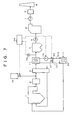
- FIG. 7 shows a block diagram of an embodiment, with which the exit exhaust gas temperature of the heat recovery unit 11 is adjusted, without using the reheater 13 of the exhaust gas treating system shown in FIG. 1 , by exchange of heat with a component outside the exhaust gas system.
- the boiler 1, the NOx removal equipment 2, the air preheater 3, the electrostatic precipitator 4, the heat recovery unit 11, the induction fan 5, the wet flue gas desulfurizer 6, the desulfurization fan 7, the measurement unit 9, the chimney 8, the sulfur trioxide (SO 3 ) removing agent supply unit 18, the thermometer 20 at the heat recovery unit exit, and the controller 24 are the same as those of Embodiment 1 and description thereof shall be omitted.
- the heating medium that recovers heat from the exhaust gas at the heat recovery unit 11 is introduced by the heating medium circulating duct 15-1 into a feed-water heater (cooler for air) 25 and after performing feed-water heating of the boiler 1, the heating medium is introduced again into the heat recovery unit 11 by the heating medium circulating duct 15-2.
- the heating medium is circulated between the heat recovery unit 11 and feed-water heater 25 by the pump 10.
- the exhaust gas thermometer 20 is disposed to measure the exit exhaust gas temperature of the heat recovery unit 11. Also, the controller 24 is installed to determine the amount of the heating medium circulated by the heating medium pump 10, etc., to control the exit exhaust gas temperature of the heat recovery unit 11 based on the measurement result of the exhaust gas thermometer 20.
- the control of the exhaust gas temperature by the heating medium flow rate may also be performed by using a means that cools the heating medium, by using a means that heats the heating medium, or by installing a bypass tube 26 that shortcuts an entrance and an exit of the heating medium ducts 15-1 and 15-2 passing through the heat recovery unit 11 and using a heating medium flow control valve 27 for adjusting the heating medium flow rate inside the bypass tube 26.
- the configuration, shown in FIG. 2 having the SO 3 concentration meter 21, measuring the SO 3 concentration in the exit exhaust gas of the dry electrostatic precipitator 4, the hydrogen chloride concentration meter 22, measuring the hydrogen chloride concentration in the exhaust gas, and the heavy metal concentration meter 23, measuring the heavy metal concentration, may be adopted.
- the neutralizing agent supplying amount from the SO 3 removing agent supply unit 18 is controlled based on a command from the controller 24 based on a measurement value of at least one among the SO 3 concentration meter 21, the hydrogen chloride concentration meter 22, and the heavy metal concentration meter 23 that measures the heavy metal concentration.
- the present system because the boiler feed-water is heated, a contribution can be made to improving the efficiency of the boiler. Also with the present system, because the exhaust gas, which is made by the sulfur trioxide removing agent to have hardly any sulfur trioxide (SO 3 ) existing therein, is cooled by the heat recovery unit 11, mercury and other heavy metals in the exhaust gas were adsorbed effectively to the soot/dust, the concentrations of mercury and other heavy metals in the recovered ash were significantly increased, not less than 50% of the mercury in the exhaust gas could be removed, and with the inclusion of the removal of mercury at the wet flue gas desulfurizer 6 in the rear stage, not less than 99% of the mercury in the exhaust gas could be removed.
- SO 3 sulfur trioxide
- the concentrations of mercury and other heavy metals in the exhaust gas discharged from a chimney, etc. can be reduced.
- the present invention thus has applicability not only to environmental fields but to industry and various other technical fields as an art of effectively reducing heavy metals emitted by combustion.
- combustion apparatus NOx removal equipment 3 air preheater 4 dry electrostatic precipitator 5 induction fan 6 wet flue gas desulfurizer 7 boost-up fan 8 chimney 9 measurement unit 10 pump 11 heat recovery unit 13 reheater 15 heating medium circulating duct 16 mercury adsorbent supply unit 18 SO 3 removing agent supply unit 20 thermometer 21 SO 3 concentration meter 22 hydrogen chloride concentration meter 23 heavy metal concentration meter 24 controller 25 feed-water heater 26 bypass line 27 heating medium flow control valve 28 boiler feed-water line thermometer
Abstract
Description
- The present invention relates to an exhaust gas treating method and apparatus and particularly relates to an apparatus and a method, which are for reducing trace component concentrations in an exhaust gas discharged from a chimney and with which trace component removal performance in a dry precipitator is improved to remove trace heavy metal components in the exhaust gas.
- Mercury and other heavy metals are contained in addition to nitrogen oxides and sulfur oxides in an exhaust gas discharged from a thermal power plant boiler, etc., which is a combustion apparatus that uses coal or other fossil fuel. Although the nitrogen oxides are removed by NOx removal equipment and the sulfur oxides are removed by a desulfurizer, mercury, selenium, cadmium, chromium, lead, zinc, and other heavy metals cannot be removed by the NOx removal equipment or desulfurizer and cannot be trapped completely by a precipitator for removing soot/dust in the exhaust gas. Because these heavy metals are high in toxicity, emission restrictions thereof have recently become stricter. Methods for removing heavy metals contained in the exhaust gas, particularly mercury, which is high in toxicity, are being examined.
-
FIG. 8 illustrates one such method and shows an exhaust gas treating system applied to remove mercury in an exhaust gas from a waste incinerator orother combustion apparatus 1. With this exhaust gas treating system, the exhaust gas from thecombustion apparatus 1 is first treated byNOx removal equipment 2 to remove nitrogen oxides, and combustion air to be used in thecombustion apparatus 1 is then heated by the exhaust gas in anair preheater 3. Soot/dust in the exhaust gas discharged from theair preheater 3 are then trapped by aprecipitator 4, the exhaust gas discharged from theprecipitator 4 is guided by aninduction fan 5 to a wetflue gas desulfurizer 6 to remove sulfur oxides in the exhaust gas, and the exhaust gas is discharged by a boost-upfan 7 into air from achimney 8. Ameasurement unit 9 for measuring concentrations of the sulfur oxides, nitrogen oxides, heavy metals (Hg), etc., in the exhaust gas is disposed at an upstream side of thechimney 8 to monitor concentrations of these components in the exhaust gas. - The exhaust gas treating system shown in
FIG. 8 is characterized in that a mercury adsorbent is added by a mercuryadsorbent supply unit 16, etc., into the exhaust gas at an entrance (front stage) of theprecipitator 4, and with this exhaust gas treating system, the exhaust gas at the entrance (front stage) of theprecipitator 4 is in a temperature range (150 to 240°C) in which a mercury adsorption performance of activated carbon, etc., is highest and the activated carbon, etc., to which mercury has become adsorbed, is recovered by the precipitator 4 (see, for example, Non-PatentDocument 1, etc.). -
FIG. 9 shows an exhaust gas treating system applied to removing mercury in an exhaust gas from a thermal power plant boiler, and with this system, heavy metal concentrations in the exhaust gas that is discharged to the atmosphere are adjusted to be within predetermined ranges by lowering an exhaust gas temperature to economically remove heavy metals in the exhaust gas without using an absorbing agent for absorbing the heavy metals in the exhaust gas. - With the exhaust gas treating system shown in
FIG. 9 , the exhaust gas from the boiler orother combustion apparatus 1 is supplied to theNOx removal equipment 2 to be removed of the nitrogen oxides and is thereafter used for heating the combustion air in theair preheater 3. A heating medium in aheat recovery unit 11 is then heated by the exhaust gas discharged from theair preheater 3, the soot/dust in the exhaust gas that has been lowered in temperature and is discharged from theheat recovery unit 11 are trapped efficiently by theprecipitator 4, and the exhaust gas discharged from theprecipitator 4 is guided by theinduction fan 5 to the wetflue gas desulfurizer 6 to be desulfurized. The exhaust gas discharged from the wetflue gas desulfurizer 6 is reheated by areheater 13 using the heating medium that is circulatingly supplied from theheat recovery unit 11 via heating medium circulating ducts 15-1 and 15-2, and is discharged by the boost-upfan 7 into air from the chimney 8 (Patent Document 1). Themeasurement unit 9 for measuring the concentrations of the sulfur oxides, nitrogen oxides, heavy metals, etc., in the exhaust gas before discharge from thechimney 8 is also disposed in the system shown inFIG. 9 to monitor the concentrations of these components in the exhaust gas. - The exhaust gas treating system shown in
FIG. 9 makes use of the fact that the heavy metals in the exhaust gas become attached more readily to solid surfaces of ash particles, etc., the lower the exhaust gas temperature, and the heavy metals in the ash particles can be recovered by an appropriate method or a treatment for preventing elution from the ash particles can be applied. InPatent Document 1, it is disclosed that a heavy metal concentration in the exhaust gas can be suppressed by a method of measuring the concentration of the heavy metal (Hg) in the exhaust gas discharged from the wetflue gas desulfurizer 6 in the exhaust gas treating system shown inFIG. 9 and adjusting one or more among: a pH of an absorbing solution used in the wetflue gas desulfurizer 6; an oxidizing air flow rate; and a wastewater flow rate; so that a measurement value of the heavy metal concentration falls within a predetermined range. - Non-Patent Document 1: Tatsuhiro Fujii and six others, "Development and Practical Application of a Comprehensive Exhaust Gas Treating System for Bag Filter Type Municipal Waste Incinerator," Hitachi Zosen Technical Review, Hitachi Shipbuilding Corporation, June, 1992, Vol. 53, No. 2, p. 23-30.
- Patent Document 1: International Patent Publication No.
2004/023040 Pamphlet - According to consideration by the present inventors, with the exhaust gas treating system described in Non-Patent
Document 1 described above, in a case where coal that contains a large amount of sulfur is used as the fuel of the boiler, etc., the heavy metals in the exhaust gas generated are hardly adsorbed by the activated carbon that is the adsorbent and remain contained as they are in the exhaust gas that is supposed to have been subject to exhaust gas treatment. It was also found that with the exhaust gas treating system described inPatent Document 1, the heavy metals in the exhaust gas are not recovered much even if the exhaust gas temperature is lowered in the case where coal that contains a large amount of sulfur is used as the fuel of the boiler, etc. - An object of the present invention is to provide an exhaust gas treating method and apparatus that effectively removes heavy metals in an exhaust gas even in a case where coal that contains a large amount of sulfur is used as a fuel.
- The object of the present invention can be achieved by the following solutions.
- A first aspect of the present invention provides an exhaust gas treating method including the steps of: preheating a combustion air of a
combustion apparatus 1 by an exhaust gas discharged from thecombustion apparatus 1; recovering heat from the exhaust gas by aheat recovery unit 11 after the air preheating; and recovering soot/dust in the exhaust gas at an exit of theheat recovery unit 11 by adry precipitator 4; and with this method, a sulfur trioxide removing agent is supplied into the exhaust gas at an upstream side of an entrance of theheat recovery unit 11. - A second aspect of the present invention provides the exhaust gas treating method according to the first aspect where an exhaust gas temperature at the exit of the
heat recovery unit 11 is lowered to near a dew point temperature of sulfur trioxide. - A third aspect of the present invention provides the exhaust gas treating method according to the first aspect where a nitrogen oxide in the exhaust gas is denitrated by a denitration catalyst before the air preheating and a sulfur oxide in the exhaust gas is desulfurized at the exit of the
dry precipitator 4. - A fourth aspect of the present invention provides the exhaust gas treating method according to the second aspect where the heat of the exhaust gas is recovered by a heating medium in the
heat recovery unit 11, the heating medium is circulatingly supplied to areheater 13, disposed for heating the desulfurized exhaust gas by the heating medium supplied from theheat recovery unit 11, and the exhaust gas temperature at the exit of theheat recoveryunit 11 is lowered to near the dew point temperature of sulfur trioxide by adjusting at least one among a heating medium circulation amount, a heating medium heating amount, and a heating medium cooling amount. - A fifth aspect of the present invention provides the exhaust gas treating method according to the first aspect where a sulfur trioxide reducing agent or a sulfur trioxide neutralizing agent is used as the sulfur trioxide removing agent.
- A sixth aspect of the present invention provides the exhaust gas treating method according to the first aspect where a sulfur trioxide adsorbent is used as the sulfur trioxide removing agent.
- A seventh aspect of the present invention provides the exhaust gas treating method according to the first aspect where at least one among a sulfur trioxide concentration, a chlorine concentration, and a heavy metal concentration in the exhaust gas at the exit of the
dry precipitator 4 is measured and an amount of the sulfur trioxide removing agent that is in accordance with the measured concentration is supplied into the exhaust gas. - An eighth aspect of the present invention provides an exhaust gas treating apparatus including: an
air preheater 3, preheating a combustion air of thecombustion apparatus 1 by an exhaust gas discharged from thecombustion apparatus 1; aheat recovery unit 11, recovering heat from the exhaust gas at an exit of theair preheater 3; and adry precipitator 4, recovering soot/dust in the exhaust gas at an exit of theheat recovery unit 11; which are successively disposed from an upstream side to a downstream side of an exhaust gas duct of acombustion apparatus 1, and further including: a sulfur trioxide removingagent supply unit 18, supplying a sulfur trioxide removing agent into the exhaust gas at an upstream side of an entrance of theheat recovery unit 11. - A ninth aspect of the present invention provides the exhaust gas treating apparatus according to the eighth aspect further including an exhaust
gas temperature controller 24, performing control to lower an exhaust gas temperature at the exit of theheat recovery unit 11 to near a dew point temperature of sulfur trioxide. - A tenth aspect of the present invention provides the exhaust gas treating apparatus according to the eighth aspect, further including
NOx removal equipment 2, denitrating a nitrogen oxide in the exhaust gas generated from thecombustion apparatus 1 and disposed at an upstream side of an entrance of theair preheater 3; and adesulfurizer 6, desulfurizing a sulfur oxide in the exhaust gas at an exit of thedryprecipitator 4. - An eleventh aspect of the present invention provides the exhaust gas treating apparatus according to the ninth aspect where the
heat recovery unit 11 is made up of a set of heat exchanger tubes that recover the heat of the exhaust gas into a heating medium, and the exhaust gas treating apparatus further includes: areheater 13, made up of a set of heat exchanger tubes that heat the exhaust gas at an exit of thedesulfurizer 6 by the heating medium supplied from theheat recovery unit 11, or acooler 25, made up of a set of heat exchanger tubes that cool the heating medium supplied from theheat recovery unit 11; a circulation line 15, making the heat exchanger tubes respectively disposed in theheat recovery unit 11 and thereheater 13 or the heat exchanger tubes respectively disposed in theheat recovery unit 11 and thecooler 25 communicate to make the heating medium circulate in interiors of the heat exchanger tubes; and an adjustingmean 10, adjusting, by the exhaustgas temperature controller 24, at least one among a circulation amount of the heating medium flowing through the circulation line 15, a heating amount of the heating medium flowing through the circulation line 15, and a cooling amount of the heating medium flowing through the circulation line 15. - A twelfth aspect of the present invention provides the exhaust gas treating apparatus according to the eighth aspect where a sulfur trioxide reducing agent supply unit or a sulfur trioxide neutralizing agent supply unit is used as the sulfur trioxide removing
agent supply unit 18. - A thirteenth aspect of the present invention provides the exhaust gas treating apparatus according to the eighth aspect where a sulfur trioxide adsorbent supply unit is used as the sulfur trioxide removing
agent supply unit 18. - A fourteenth aspect of the present invention provides the exhaust gas treating apparatus according to the eighth aspect further including:
measurement units 21 to 23, measuring at least one among a sulfur trioxide concentration, a chlorine concentration, and a heavy metal concentration in the exhaust gas at the exit of thedry precipitator 4; an adjusting mean, adjusting a supplying amount supplied from the sulfur trioxide removingagent supply unit 18; and a sulfur trioxide removing agent supplyingamount controller 24, controlling the adjusting mean to supply the sulfur trioxide removing agent of an amount that is in accordance with the measurement values of themeasurement units 21 to 23. - As the
heat recovery unit 11 according to the first and eighth aspects, a configuration, where a set of heat exchanger tubes, through which the heating medium that recovers the heat of the exhaust gas flows, is disposed to perform heat exchange with heat releasing equipment disposed separately from the above-described exhaust gas system, or a configuration, where cooling water is sprayed directly inside theheat recovery unit 11, etc., is used. - A portion of sulfur dioxide (SO2) in an exhaust gas that is generated when a fossil fuel is combusted reacts with oxygen in the exhaust gas due to a catalytic action of a denitration catalyst, etc., and is converted to sulfur trioxide (SO3). Although a conversion rate of sulfur dioxide (SO2) to sulfur trioxide (SO3) depends on conditions, it is approximately 1 to 3%. Although a concentration of sulfur dioxide in an exhaust gas discharged from a
combustion apparatus 1, which is a coal burning boiler, etc., is generally approximately 300 to 3000ppm and thus a concentration of sulfur trioxide in the exhaust gas is approximately 3 to 90ppm, with a high sulfur content coal, with which a sulfur concentration in coal exceeds 4%, the concentration of sulfur trioxide may exceed 100ppm. - According to research by the present inventors, it is clear that in a case where a fossil fuel with a high sulfur content is combusted, heavy metals in the combustion exhaust gas cannot be removed effectively by the conventionally practiced exhaust gas treating systems disclosed in Non-Patent
Document 1,Patent Document 1, etc. - Because as mentioned above, the amounts of sulfur oxides (SO2 and SO3) generated in the exhaust gas when a fossil fuel with a comparatively high sulfur content is combusted are high in comparison to the amounts of the sulfur oxides in the exhaust gas generated when a fuel of comparatively low sulfur content is combusted, the present inventors presumed the sulfur oxides in the exhaust gas to be an impediment against the removal of heavy metals.
- The present inventors have already found that the sulfuric acid mist that is generated under an atmosphere in which the temperature of the sulfur trioxide has decreased to not more than the dew point is adsorbed by ash particles that exist at a considerable amount in the exhaust gas (Japanese Published Unexamined Patent Application No.
2004-154683 - The dew point of sulfur trioxide depends on the amounts of the sulfur trioxide and water, and whereas the dew point of sulfur trioxide in a case of an exhaust gas of a boiler in which coal with a normal sulfur content (coal with a sulfur concentration of not more than 3%) is combusted is 120 to 160°C, the dew point of sulfur trioxide in a case of an exhaust gas of a boiler in which coal with a high sulfur content (coal with a sulfur concentration exceeding 3%) is combusted may be not less than 160°C. By adjusting the exhaust gas temperature to be not more than the dew point of sulfur trioxide (SO3) that is at least not more than 180°C, the sulfur trioxide (SO3) in the exhaust gas can be condensed and converted to sulfuric acid mist (H2SO4).
- By thus lowering the temperature of the exhaust gas, which contains a large amount of sulfur trioxide (SO3) generated from high sulfur content coal, to not more than the dew point of sulfur trioxide, the sulfur trioxide that cannot be recovered as gypsum even in a wet flue gas desulfurizer can be recovered as sulfuric acid mist. Moreover, an effect that the sulfuric acid mist becomes adsorbed by the ash particles that exist at a considerable amount in the exhaust gas is provided. Because the amount of the sulfuric acid mist that becomes adsorbed to the ash particles is a small amount, a heavy metal adsorption performance of the ash particles is hardly lowered.
- It is thus considered that by placing the sulfuric acid mist (H2SO4), which is generated at a high concentration in a boiler using high sulfur content coal, under conditions of becoming actively adsorbed by the ash particles and recovering the sulfuric-acid-mist-adsorbed ash particles thus obtained, a state where hardly any sulfur trioxide (SO3) exists in the exhaust gas can be realized to prevent the sulfur components in the exhaust gas from becoming discharged into the atmosphere.
- However, as mentioned above, it has recently become a problem that even when either of the methods of Non-Patent
Document 1 andPatent Document 1 is used, the concentrations of mercury and other heavy metals in the exhaust gas cannot be lowered from the exhaust gas of a boiler using high sulfur content coal. - As mentioned above, as a result of diligently examining why the phenomenon of not being able to recover heavy metals occurs, it was hypothesized that "ash particles to which a large amount of sulfuric acid mist has become adsorbed lose an ability to adsorb mercury and other heavy metals in the exhaust gas," and the present invention was completed by finding out that by implementing measures based on this hypothesis, the concentrations of mercury and other heavy metals can be lowered even with an exhaust gas of a combustion apparatus using high sulfur content coal.
- That is, the present inventors considered that when mercury and other heavy metals coexist with sulfur trioxide (SO3), which is generated in large amounts, in an exhaust gas, the sulfur trioxide (SO3) becomes adsorbed with priority over mercury and other heavy metals to adsorption active sites of non-combusted portions in the ash, etc., so that with nearly all of the active sites, the adsorption of mercury and other heavy metals is impeded and the concentrations of mercury and other heavy metals in a recovered ash are significantly lowered. It was thus hypothesized that by removing the SO3 in the exhaust gas before lowering the temperature in the exhaust gas, mercury can be adsorbed effectively to adsorption active sites of the non-combusted portions in the ash, and as a result of diligent study, the present inventors arrived at completing the present invention.
-
FIG. 3 shows mercury concentrations in ash recovered in thedry precipitator 4 when, for example, a reducing agent for removing sulfur trioxide (SO3) is sprayed at an entrance (front stage) of theheat recovery unit 11 of the exhaust gas treating system shown inFIG. 1 orFIG. 2 and the temperature of the exhaust gas entering into theprecipitator 4 is changed by aheat recovery unit 11 at an entrance (front stage) of theprecipitator 4. - In
FIG. 3 , "With reducing agent" indicates a case where, for example, a reducing agent is sprayed as a sulfur trioxide (SO3) removing agent at a molar equivalent ratio=1 with respect to sulfur trioxide at a rear stage of NOx removal equipment 2 (FIG. 1 ,FIG. 2 ) that includes a denitration catalyst with a mercury oxidizing function.FIG. 3 illustrates an example of using sodiumbisulfite as the sulfur trioxide reducing agent. By addition of such a reducing agent, the sulfur trioxide is reduced to sulfur dioxide (SO2) according to the following formula:
SO3+NaHSO3 → NaHSO4+SO2 (1)
With both the system in which the reducing agent is not sprayed and the system in which the reducing agent is sprayed, a comparison of a general case where theprecipitator 4 is set to a temperature 160°C with a case where theprecipitator 4 is set to a low temperature (110°C) corresponding to be not more than an acid dew point shows that the mercury (Hg) concentration in the ash recovered by thedry precipitator 4 in the case of the low temperature (110°C) is slightly increased with respect to that in the case of the temperature of 160°C. This is considered to be a consequence of improved performance of adsorption of mercury onto the ash particles and condensation of mercury due to heavymetals in the exhaust gas becoming readily attached to solid surfaces of the ash particles, etc., by the lowering of the exhaust gas temperature. - It can be understood that when the temperature of the exhaust gas is made low (110°C) after addition of the reducing agent, because the sulfur trioxide (SO3) is reduced to sulfur dioxide (SO2) as shown by Formula (1) and the exhaust gas temperature thus becomes low in a state where there is hardly any sulfur trioxide (SO3) in the exhaust gas, mercury becomes adsorbed effectively to the active sites of the non-combusted portions, etc., in the ash without the sulfur trioxide (SO3) becoming adsorbed to the active sites in the ash and the mercury concentration in the recovered ash thus increases significantly.
-
FIG. 4 shows a variation of the mercury concentration in the exhaust gas when a neutralizing agent (Na2CO3) is added at molar equivalents with respect to the sulfur trioxide (SO3) in the exhaust gas. The mercury concentration in the exhaust gas was minimized when the neutralizing agent (Na2CO3) was added at an amount of 1 molar equivalent with respect to the sulfur trioxide (SO3). -
FIG. 5 shows a variation of concentrations of acidic substances (SO3, HCl) in the exhaust gas when the neutralizing agent (Na2CO3) is added at molar equivalents with respect to the sulfur trioxide (SO3) in the exhaust gas. Here, a control range inFIG. 5 indicates an appropriate range of an alkali supplying amount for improving the Hg removal performance. - It can be understood that because, besides the sulfur trioxide (SO3), the concentration of chlorine component (Cl2 or HCl) that improves the mercury removal performance is also decreased when the neutralizing agent (Na2CO3) is added to the exhaust gas excessively, it is preferable to measure the concentration of one or the concentrations of two or more among sulfur trioxide (SO3), the chlorine component (Cl2 or HCl), and mercury in the exhaust gas at the exit of the
precipitator 4 and to spray the neutralizing agent at an amount that is in accordance with the measured concentration into the exhaust gas. The neutralizing agent is preferably added at a supplying amount close to 1 molar equivalent with respect to the sulfur trioxide (SO3) in the exhaust gas and not more than 1 molar equivalent. - Also, although most of the heavy metals in the exhaust gas exist as a gas at a high temperature region in the
combustion apparatus 1, the heavy metals become readily attached to the solid surfaces of the ash particles, etc., when the temperature of the exhaust gas decreases. This is because the lower the temperature of the metals and compounds thereof, the lower their vapor pressures and the more difficult it is for the metals and compounds thereof to exist as a gas. Thus, with theprecipitator 4, the lower the temperature of the exhaust gas, the higher the recovery of the heavy metals with the ash particles. The heavymetals in the recovered ash can be removed and recovered from the ash as necessary or can be stabilized so as not to become eluted from the ash particles. However, when the temperature of the exhaust gas in theprecipitator 4 becomes too low, the ash particles become readily condensed in theprecipitator 4 and become difficult to be discharged from an ash recovery unit (hopper, etc.) at a lower portion of theprecipitator 4. It is thus preferable to lower the exhaust gas temperature to a level that enables the ash to be recovered with stability from theprecipitator 4. - By thus reducing the concentration of the sulfur trioxide in the exhaust gas and removing the sulfur trioxide at the entrance (front stage) of the
heat recovery unit 11, it also becomes possible to prevent corrosion of the heat exchanger tubes of theheat recovery unit 11 as well as theprecipitator 4 and other equipment disposed at the rear stage of theheat recovery unit 11. Furthermore, by removing the sulfur trioxide at the entrance (front stage) of theheat recovery unit 11, adsorption of sulfur trioxide to the non-combusted portions and other adsorption components in the ash can be prevented to prevent degradation of the performance of adsorption of mercury and other heavy metals by the sulfur trioxide removing agent. Because mercury and other heavy metals thus become adsorbed to the ash at the rear stage of theheat recovery unit 11, the mercury and other heavy metals can be removed efficiently. As a consequence of using the sulfur trioxide (SO3) removing agent and lowering the temperature of the exhaust gas, the mercury concentration in the recovered ash is increased significantly. -
FIG. 6 shows a relationship of a concentration of an acidic substance (SO3, Cl2, or HCl) in the exhaust gas and an amount of reducing agent supplied to the exhaust gas. Because, besides the sulfur trioxide (SO3), the concentration of chlorine (Cl2 or HCl) that improves the mercury removal performance is also decreased when the reducing agent is added to the exhaust gas excessively, it is preferable to measure the concentration of one or the concentrations or two or more among sulfur trioxide (SO3), the chlorine component (Cl2 or HCl), and mercury in the exhaust gas at the exit of thedry precipitator 4 and to spray the reducing agent at an amount that is in accordance with the measured concentration into the exhaust gas.FIG. 6 illustrates an example where NaHSO3 is used as the reducing agent. - The concentration of sulfur trioxide (SO3) can be controlled by detecting the hydrogen chloride concentration by a commercially available HCl meter, detecting the mercury concentration by a commercially available continuous mercury monitor, detecting the sulfur trioxide concentration by a commercially available sulfur trioxide concentration meter, and supplying a predetermined amount of the reducing agent into the exhaust gas based on the detected concentration of at least one of these compounds.
- It is thus found that in an exhaust gas system in which sulfur trioxide (SO3) does not exist, the mercury in the exhaust gas becomes adsorbed effectively to active sites of non-combusted portions, etc., in the ash. It is thus found that, even with an exhaust gas of a boiler using high sulfur content coal, mercury and other heavy metals can be removed effectively by achieving a state where hardly any sulfur trioxide (SO3) is contained in the exhaust gas.
- According to the present invention, the heavy metal concentration in the exhaust gas discharged from the
combustion apparatus 1 can be reduced. - According to the first and eighth aspects of the present invention, mercury and other heavy metals in the exhaust gas can be reduced with respect to the exhaust gas exit concentration of the
combustion apparatus 1 in the case of combusting high sulfur content coal. Also, because sulfur trioxide (SO3) can be removed at the front stage of theheat recovery unit 11, corrosion of the heat exchanger tubes of theheat recovery unit 11 and theprecipitator 4 and other equipment disposed at the rear stage of theheat recovery unit 11 can be prevented. - According to the second and ninth aspects of the present invention, in addition to the effects of the first and eighth aspects of the present invention, the lowering of the exhaust gas temperature provides the effects of making mercury and other heavy metals more readily adsorbed to the ash particles and lowering the sulfur trioxide concentration in the exhaust gas. Because the sulfur trioxide concentration is low, the amount of the sulfuric acid mist that becomes adsorbed to the ash particles is low and the performance of adsorption of mercury and other heavy metals to the ash particles hardly degrades.
- According to the third and tenth aspects of the present invention, in addition to the effects of the first and eighth aspects of the present invention, mercury and other heavy metals in the exhaust gas in the case of combusting high sulfur content coal can be reduced by almost 99% with respect to the exhaust gas exit concentration of the
combustion apparatus 1 and the nitrogen oxides and sulfur oxides in the exhaust gas can also be removed. - According to the fourth and eleventh aspects of the present invention, in addition to the effects of the second and ninth aspects of the present invention, the exhaust gas temperature can be adjusted readily within the same exhaust gas system because the exhaust gas temperature at the exit of the
heat recovery unit 11 is adjusted by at least one among the amount of circulation of the heating medium between theheat recovery unit 11 and thereheater 13 or the cooler 25 connected to theheat recovery unit 11 by the circulating line 15, through which the heating medium flows, the heating medium heating amount, and the heating medium cooling amount. - According to the fifth and twelfth aspects of the present invention, in addition to the effects of the first and eighth aspects of the present invention, the sulfur trioxide is reduced or neutralized by the reducing agent or the neutralizing agent and can thereby be removed reliably.
- According to the sixth and thirteenth aspects of the present invention, in addition to the effects of the first and eighth aspects of the present invention, the sulfur trioxide is adsorbed by the adsorbent and can thereby be removed reliably.
- According to the seventh and fourteenth aspects of the present invention, in addition to the effects of the first and eighth aspects of the present invention, the appropriate amount of the sulfur trioxide removing agent can be added into the exhaust gas without degrading the performance of removal of heavy metals in the exhaust gas, and the added amount can be managed appropriately.
- Embodiments of an exhaust gas treating system according to the present invention shall now be described along with the drawings.
-
FIG. 1 is a block diagram of an exhaust gas treating system of an embodiment of the present invention. Concentrations of exhaust gas components discharged from a boiler are: a soot/dust concentration of 20g/m3N; a NOx concentration of 200ppm; a SOx concentration of 4000ppm; and an Hg concentration of 10µg/ m3N. As shown inFIG. 1 , with the exhaust gas treating system according to the present embodiment, an exhaust gas discharged from the boiler orother combustion apparatus 1 is introduced intoNOx removal equipment 2, and, after elimination of nitrogen oxides in the exhaust gas to not more than 20ppmby a denitration catalyst, etc., inside theNOx removal equipment 2, the exhaust gas is introduced into anair preheater 3. At a front stage of theair preheater 3, a sulfur trioxide (SO3) removing agent is added by a sulfur trioxide (SO3) removingagent supply unit 18. - A method for adding the SO3 removing agent is not restricted in particular, and supplying in a form of a solid powder or aqueous solution is possible and supplying can be performed simply by spraying the removing agent into an exhaust gas flue by a spray type nozzle, etc. With the present embodiment, an example of spraying a reducing agent as the sulfur trioxide (SO3) removing agent, is illustrated, and in this example, SO3 is reduced to SO2. Although the sulfur trioxide (SO3) removing agent is sprayed into the flue between the
NOx removal equipment 2 and theair preheater 3 in the present embodiment, the setting position is not restricted in particular as long as it is at a front stage of aheat recovery unit 11. - The exhaust gas introduced into the
air preheater 3 undergoes heat exchange with a combustion air that is supplied to thecombustion apparatus 1 and, upon being cooled, for example, to 120 to 170°C, the exhaust gas is introduced into theheat recovery unit 11. The heat of the exhaust gas introduced into theheat recovery unit 11 is recovered by heat exchange with a heating medium that flows through a heat exchanger tube and the exhaust gas is preferably cooled to increase a solid adsorption performance of non-combusted portions in ash. By the exhaust gas being lowered in temperature, mercury and other heavy metals become readily adsorbed to ash particles. The exhaust gas temperature is preferably lowered to near a dew point of sulfur trioxide, and in this case, the sulfur trioxide in the exhaust gas becomes converted to sulfuric acid mist so that hardly any sulfur trioxide remains contained in the exhaust gas. Because the sulfur trioxide concentration is low at this stage, the amount of sulfuric acid mist that becomes adsorbed to the ash particles is low and the performance of adsorption of mercury and other heavy metals to the ash particles hardly degrades. - The exhaust gas that has passed through the dry
electrostatic precipitator 4 is raised in pressure and introduced by aninduction fan 5 into a wetflue gas desulfurizer 6, which is based on a spray type limestone-gypsum method and is one example of a desulfurizer, and sulfur oxides (SOx) in the exhaust gas are removed by gas-liquid contact of the exhaust gas and an exhaust gas absorbing solution. The exhaust gas, which has been cooled to a saturation gas temperature in the wetflue gas desulfurizer 6, is raised in temperature by areheater 13 and then discharged from achimney 8 via adesulfurization fan 7. As with theheat recovery unit 11, thereheater 13 is a heat exchanger having a heat exchanger tube through which the heating medium flows, and the exhaust gas is raised in temperature, for example, to 90 to 110°C by heat exchange with the heating medium that flows through the heat exchanger tube. The heat exchanger tubes of theheat recovery unit 11 and thereheater 13 are made to communicate by the heating medium circulating ducts 15-1 and 15-2, and the heating medium is made to circulate between theheat recovery unit 11 and thereheater 13 by apump 10. Anexhaust gas thermometer 20 is disposed to measure an exit exhaust gas temperature of theheat recovery unit 11. Furthermore, acontroller 24 is installed to determine an amount of the heating medium circulated by theheating medium pump 10, etc., to control the exit exhaust gas temperature of theheat recovery unit 11 based on a measurement result of theexhaust gas thermometer 20. - Although not illustrated, control of the exhaust gas temperature by the heating medium flow rate may also be performed by using one or more among a means that cools the heating medium, a means that heats the heating medium, and a means of adjusting the heating medium flow rate in a bypass tube that is installed so as to shortcut an entrance and an exit of the heating medium duct passing through the
heat recovery unit 11. The control of the exhaust gas temperature by the heating medium flow rate is performed in common in other embodiments as well. - The exit exhaust gas temperature of the
heat recovery unit 11 may also be adjusted, without using thereheater 13, by exchange of heat with a component outside the exhaust gas system shown inFIG. 1 . - With the exhaust gas treating system shown in
FIG. 1 , the sulfur trioxide (SO3) concentration can be lowered as described above Formula (1) by adding, for example, sodium bisulfite (sodiumhydrogen sulfite; NaHSO3) as a reducing agent. And by controlling the exhaust gas temperature at the exit of theheat recovery unit 11 by the heating medium circulation amount of thepump 10, etc., based on the exhaust gas temperature measurement value of theexhaust gas thermometer 20, the amount of adsorption of the mercury in the exhaust gas to the ash can be increased to improve removal efficiency of the mercury in the exhaust gas. - As already described,
FIG. 6 shows the relationship of the concentration of an acidic substance (SO3, Cl2, or HCl) in the exhaust gas and the amount of the reducing agent supplied into the exhaust gas. Although not illustrated, because, besides the sulfur trioxide (SO3), the concentration of chlorine (Cl2 or HCl) that improves the mercury removal performance is also decreased when the reducing agent (NaHSO3) is added to the exhaust gas excessively, it is preferable to measure the concentration of one or the concentrations of two or more among sulfur trioxide (SO3), the chlorine component (Cl2 or HCl), and mercury in the exhaust gas at the exit of thedry precipitator 4 and to spray the reducing agent at an amount that is in accordance with the measured concentration into the exhaust gas. - Besides sodiumbisulfite (NaHSO3), sodiumsulfite (Na2SO3) potassiumbisulfite (KHSO3), potassium sulfite (K2SO3), calcium sulfite (CaSO3), etc., may be used as the reducing agent. Whereas the sulfur trioxide (SO3) concentration in the exhaust gas is not more than 50ppm in a case where coal, used for example in a coal-burning boiler as the
combustion apparatus 1, has a sulfur content of not more than 2%, when coal with a high sulfur content of not less than 4% is combusted, the sulfur trioxide (SO3) concentration exceeds 100pm. It is presumed that, under such an exhaust gas condition where a comparatively large amount of sulfur trioxide (SO3) is contained, sulfur trioxide (SO3) became adsorbed to active sites of the non-combusted portions in the ash and the adsorbed sulfur trioxide (SO3) inhibited the adsorption of the mercury in the exhaust gas. - With the exhaust gas treating system according to the present embodiment, because the sulfur trioxide (SO3) in the exhaust gas at the exit side of the
heat recovery unit 11 is reduced by the addition of the reducing agent or other sulfur trioxide (SO3) removing agent, the amount of mercury adsorbed to the ash is increased and not less than 50% of the mercury existing in the exhaust gas can be removed at the dryelectrostatic precipitator 4. With inclusion of removal of mercury at the wetflue gas desulfurizer 6 disposed at the rear stage of theheat recovery unit 11, not less than 99% of the mercury in the exhaust gas could be removed. Also, by suitably adding the sulfur trioxide (SO3) reducing agent into the exhaust gas to reduce and remove the sulfuric acid mist, corrosion of the equipment at stages at the rear of the SO3 removingagent supply unit 18 can be prevented and corrosion of the units could be prevented even at one year from a start of operation. The mercury concentration in the exhaust gas could be confirmed to meet regulation values by monitoring by a continuous mercury monitor incorporated in ameasurement unit 9 disposed in front of thechimney 8, and the NOx and SOx in the exhaust gas could be confirmed to respectively meet regulation values by monitoring by respective monitors incorporated in themeasurement unit 9. Although plant operation is discontinued if the regulation values are deviated from, deviations from the regulation values do not occur with the present embodiment. - With
Embodiment 2 of the present invention, shown inFIG. 2 , an example of using a neutralizing agent as the sulfur trioxide (SO3) removing agent is illustrated. By addition, for example, of sodium carbonate (Na2CO3) as the neutralizing agent from the SO3 removingagent supply unit 18 shown inFIG. 2 , the concentration of SO3 in the exhaust gas is reduced according to Formula (2) shown below:
SO3+Na2CO3 → Na2SO4+CO2 (2)
-
FIG. 4 shows the variation of the mercury concentration in the exhaust gas when the neutralizing agent (Na2CO3) is added at molar equivalents with respect to the sulfur trioxide (SO3) in the exhaust gas, and the mercury concentration in the exhaust gas was minimized when the neutralizing agent (Na2CO3) was added at an amount of 1 molar equivalent with respect to the sulfur trioxide (SO3). -
FIG. 5 shows the variation of concentrations of acidic substances (SO3, HCl) in the exhaust gas when the neutralizing agent (Na2CO3) is added at molar equivalents with respect to the sulfur trioxide (SO3) in the exhaust gas, and the control range of the added amount of the neutralizing agent (Na2CO3) indicates the appropriate range of the alkali supplying amount for improving the Hg removal performance. - It can be understood that because, besides the sulfur trioxide (SO3), the concentration of chlorine component (Cl2 or HCl) that improves the mercury removal performance is also decreased when the neutralizing agent (Na2CO3) is added to the exhaust gas excessively, it is preferable to measure the concentration of one or the concentrations of two or more among sulfur trioxide (SO3), the chlorine component (Cl2 or HCl), and mercury in the exhaust gas at the exit of the
precipitator 4 and to spray the neutralizing agent at an amount that is in accordance with the measured concentration into the exhaust gas. The neutralizing agent is preferably added at a supplying amount close to 1 molar equivalent with respect to the sulfur trioxide (SO3) in the exhaust gas and not more than 1 molar equivalent. - Besides sodium carbonate, sodium bicarbonate (NaHCO3), potassium carbonate (K2CO3), potassium bicarbonate (KHCO3), calcium carbonate (CaCO3), etc., which are likewise alkaline, may be used as the neutralizing agent, and the neutralizing agent is not restricted to these compounds.
- With the exhaust gas treating system according to the present embodiment, the exhaust gas from the
combustion apparatus 1 is introduced into theNOx removal equipment 2, and, after elimination of the nitrogen oxides in the exhaust gas by the denitration catalyst, etc., inside theNOx removal equipment 2, the exhaust gas is introduced into theair preheater 3. At the front stage of theair preheater 3, the sulfur trioxide (SO3) removing agent is added by the sulfur trioxide (SO3) removingagent supply unit 18 as inEmbodiment 1. With the present embodiment, an example of adding the neutralizing agent as the SO3 removing agent is illustrated, and because the configuration of other portions is the same as that ofEmbodiment 1, description thereof is omitted. - The exit exhaust gas temperature of the
heat recovery unit 11 may also be adjusted, without using thereheater 13, by exchange of heat with a component outside the exhaust gas system shown inFIG. 1 . - Although the neutralizing agent spraying position is preferably at a rear stage of the
NOx removal equipment 2, because the neutralization reaction is completed quickly, the spraying position may be at a front stage (immediately in front of the entrance) of theheat recovery unit 11. Because Na, K, Ca and other components in the neutralizing agent are components that degrade the denitration catalyst, by adding the neutralizing agent at the rear stage of theNOx removal equipment 2, degradation of the denitration catalyst can be prevented. Also, because, by an action of the denitration catalyst in theNOx removal equipment 2, a portion of sulfur dioxide gas (SO2) in the exhaust gas reacts with oxygen in the exhaust gas to be converted to sulfur trioxide (SO3), it is preferable to perform treatment by spraying of the neutralizing agent after the SO3 amount increases. However, because as mentioned above, the neutralization reaction is completed quickly, the neutralizing agent may be added at the front stage of theheat recovery unit 11. - With the exhaust gas treating system shown in
FIG. 2 , an SO3 concentration meter 21, measuring the SO3 concentration in the exit exhaust gas of the dryelectrostatic precipitator 4, a hydrogenchloride concentration meter 22, measuring a hydrogen chloride concentration in the exhaust gas, and a heavymetal concentration meter 23, measuring a heavy metal concentration, are disposed. - With the present embodiment, a neutralizing agent supplying amount from the SO3 removing
agent supply unit 18 is controlled based on a command from thecontroller 24 based on a measurement value of at least one among the SO3 concentration meter 21, the hydrogenchloride concentration meter 22, and the heavymetal concentration meter 23 that measures the heavy metal concentration. Thecontroller 24 for the neutralizing agent supplying amount may be disposed separately from or may be used in common as shown inFIG. 2 as thecontroller 24 that determines the heating medium circulating amount of theheating medium pump 10 for controlling the exit exhaust gas temperature of theheat recovery unit 11. - To prevent the chlorine amount necessary for oxidation of mercury from decreasing by a desalting reaction due to the addition of the alkali, the neutralizing agent addition amount is preferably adjusted by continuously detecting the chlorine component concentration by the hydrogen
chloride concentration meter 22 and suppressing the neutralizing agent supplying amount from the SO3 removingagent supply unit 18 before a chlorine concentration decrease amount Δ increases. - Whereas the sulfur trioxide (SO3) concentration in the exhaust gas is not more than 50ppm in the case where the coal used in a coal-burning boiler, etc., has a sulfur content of not more than 2%, when coal of a high sulfur content of not less than 4% is combusted, the sulfur trioxide (SO3) concentration exceeds 100ppm. Under such an exhaust gas condition, mercury hardly becomes adsorbed to the ash and is not removed at the
precipitator 4. - In the present embodiment, because the SO3 concentration in the exhaust gas is reduced due to neutralization of SO3 by the SO3 neutralizing agent and the exhaust gas temperature is lowered at the
heat recovery unit 11, mercury becomes adsorbed effectively to active sites of non-combusted portions in the ash, and by significant increase of the mercury concentration in the recovered ash, not less than 60% of the mercury in the exhaust gas can be removed, and with the inclusion of removal at the wetflue gas desulfurizer 6 disposed at the rear stage of theheat recovery unit 11, not less than 99% of the mercury in the exhaust gas could be removed. - At the
measurement unit 9 disposed in front of thechimney 8, the hazardous components in the exhaust gas were monitored continuously by the continuous mercury analyzer, the NOx meter, and the SOx meter and it was confirmed that the NOx concentration is not more than 20ppm ,the SOx concentration is not more than 40ppm, and the Hg concentration is not more than 0.1µg/m3N. Also, by suitably adding the SO3 neutralizing agent into the exhaust gas to neutralize and render harmless the sulfuric acid mist, the corrosion of the equipment at stages at the rear of the SO3 removingagent supply unit 18 can be prevented and the corrosion of the equipment could be prevented even at one year from the start of operation. - With
Embodiment 3 of the present invention, an example of using an adsorbent as the SO3 removing agent is illustrated. Because besides using the adsorbent as the SO3 removing agent, the present embodiment is the same asEmbodiment 1 andEmbodiment 2, description of redundant portions is omitted. - For example, powder activated carbon is added as the absorbent from the SO3 removing
agent supply unit 18 ofFIG. 1 orFIG. 2 , and the SO3 concentration in the exhaust gas is reduced by SO3 becoming adsorbed to the adsorbent. As mentioned above, it is considered that when mercury coexists with sulfur trioxide (SO3) in the exhaust gas, the SO3 becomes adsorbed with priority over mercury to the active sites of the non-combusted portions, etc., in the ash. It is thus presumed when the adsorbent is added into the exhaust gas in which sulfur trioxide (SO3) and mercury coexist, SO3 becomes adsorbed with good efficiency to the adsorption active sites of the adsorbent. - Although in the present case, powder activated carbon with an average particle diameter of 15µm was used as the adsorbent, besides this, soot/dust recovery ash (coal ash), which exhibits adsorption performance and to which the sulfuric acid mist has not become attached, silica gel, alumina, zeolite, synthetic zeolite, a metal oxide, etc., may be used.
- With the exhaust gas from which sulfur trioxide (SO3) has been removed at the front stage of the
heat recovery unit 11, mercury became adsorbed to soot/dust due to the lowering of temperature at the exit at theheat recovery unit 11 and specifically, by the addition of the adsorbent, the Hg concentration in the ash increased from 50µg/kg to 300µg/kg. - Although heavy metals besides mercury, such as selenium (Se), lead (Pb), zinc (Zn), cadmium (Cd), chromium (Cr), arsenic (As), etc., are lower in vapor pressure than mercury and trapping performance of such heavy metals by activated carbon in the
dry precipitator 4 is high, improvement of the trapping performance by application of the present invention is seen as shown in Table 1. At themeasurement unit 9 disposed in front of thechimney 8, the hazardous components in the exhaust gas were monitored continuously by the continuous mercury analyzer, the NOx meter, and the SOx meter and it was confirmed that the NOx concentration is not more than 15ppm ,the SOx concentration is not more than 30ppm, and the Hg concentration is not more than 0.2µg/m3N.[Table 1] Weight in exhaust gas (µg/m3) Sample position Cr Zn As Se Cd Sb Pb Precipitator entrance 0.483 0.748 0.191 176.256 0.055 0.097 1.350 Precipitator exit 0.471 0.603 0.289 40.005 0.028 0.021 0.314 Precipitator exit, with SO3 adsorbent 0.280 0.410 0.063 9.000 0.018 0.016 0.200 -
FIG. 7 shows a block diagram of an embodiment, with which the exit exhaust gas temperature of theheat recovery unit 11 is adjusted, without using thereheater 13 of the exhaust gas treating system shown inFIG. 1 , by exchange of heat with a component outside the exhaust gas system. - With the configuration shown in
FIG. 7 , theboiler 1, theNOx removal equipment 2, theair preheater 3, theelectrostatic precipitator 4, theheat recovery unit 11, theinduction fan 5, the wetflue gas desulfurizer 6, thedesulfurization fan 7, themeasurement unit 9, thechimney 8, the sulfur trioxide (SO3) removingagent supply unit 18, thethermometer 20 at the heat recovery unit exit, and thecontroller 24 are the same as those ofEmbodiment 1 and description thereof shall be omitted. - With the present system, the heating medium that recovers heat from the exhaust gas at the
heat recovery unit 11 is introduced by the heating medium circulating duct 15-1 into a feed-water heater (cooler for air) 25 and after performing feed-water heating of theboiler 1, the heating medium is introduced again into theheat recovery unit 11 by the heating medium circulating duct 15-2. The heating medium is circulated between theheat recovery unit 11 and feed-water heater 25 by thepump 10. - The
exhaust gas thermometer 20 is disposed to measure the exit exhaust gas temperature of theheat recovery unit 11. Also, thecontroller 24 is installed to determine the amount of the heating medium circulated by theheating medium pump 10, etc., to control the exit exhaust gas temperature of theheat recovery unit 11 based on the measurement result of theexhaust gas thermometer 20. - The control of the exhaust gas temperature by the heating medium flow rate may also be performed by using a means that cools the heating medium, by using a means that heats the heating medium, or by installing a
bypass tube 26 that shortcuts an entrance and an exit of the heating medium ducts 15-1 and 15-2 passing through theheat recovery unit 11 and using a heating mediumflow control valve 27 for adjusting the heating medium flow rate inside thebypass tube 26. - In the present system, the configuration, shown in
FIG. 2 , having the SO3 concentration meter 21, measuring the SO3 concentration in the exit exhaust gas of the dryelectrostatic precipitator 4, the hydrogenchloride concentration meter 22, measuring the hydrogen chloride concentration in the exhaust gas, and the heavymetal concentration meter 23, measuring the heavy metal concentration, may be adopted. In this case, the neutralizing agent supplying amount from the SO3 removingagent supply unit 18 is controlled based on a command from thecontroller 24 based on a measurement value of at least one among the SO3 concentration meter 21, the hydrogenchloride concentration meter 22, and the heavymetal concentration meter 23 that measures the heavy metal concentration. - With the present system, because the boiler feed-water is heated, a contribution can be made to improving the efficiency of the boiler. Also with the present system, because the exhaust gas, which is made by the sulfur trioxide removing agent to have hardly any sulfur trioxide (SO3) existing therein, is cooled by the
heat recovery unit 11, mercury and other heavy metals in the exhaust gas were adsorbed effectively to the soot/dust, the concentrations of mercury and other heavy metals in the recovered ash were significantly increased, not less than 50% of the mercury in the exhaust gas could be removed, and with the inclusion of the removal of mercury at the wetflue gas desulfurizer 6 in the rear stage, not less than 99% of the mercury in the exhaust gas could be removed. - According to the present invention, the concentrations of mercury and other heavy metals in the exhaust gas discharged from a chimney, etc., can be reduced. The present invention thus has applicability not only to environmental fields but to industry and various other technical fields as an art of effectively reducing heavy metals emitted by combustion.
-
-
FIG. 1 is a block diagram of an exhaust gas treating system according toEmbodiments -
FIG. 2 is a block diagram of an exhaust gas treating system according toEmbodiments -
FIG. 3 is a diagram showing mercury concentrations in ash recovered in a dry precipitator under various conditions using a reducing agent as an SO3 removing agent in the exhaust gas treating system according to the present invention. -
FIG. 4 shows a variation of a mercury concentration in an exhaust gas when a neutralizing agent is added at molar equivalents with respect to sulfur trioxide in the exhaust gas in the exhaust gas treating system according to the present invention. -
FIG. 5 shows a variation of concentrations of acidic substances (SO3, HCl) in the exhaust gas when the neutralizing agent is added at molar equivalents with respect to the sulfur trioxide in the exhaust gas in the exhaust gas treating system according to the present invention. -
FIG. 6 is a diagram of a relationship of a reducing agent addition amount and an acidic gas concentration in the exhaust gas treating system according to the present invention. -
FIG. 7 is a block diagram of an exhaust gas treating system with which an exit exhaust gas temperature of a heat recovery unit is adjusted by exchange of heat from outside an exhaust gas system according to the present invention. -
FIG. 8 is a block diagram of an exhaust gas treating system according to a conventional art. -
FIG. 9 is a block diagram of an exhaust gas treating system according to a conventional art. - 1
combustion apparatus 2NOx removal equipment 3air preheater 4 dryelectrostatic precipitator 5induction fan 6 wetflue gas desulfurizer 7 boost-upfan 8chimney 9measurement unit 10pump 11heat recovery unit 13 reheater 15 heatingmedium circulating duct 16 mercuryadsorbent supply unit 18 SO3 removingagent supply unit 20thermometer 21 SO3 concentration meter 22 hydrogenchloride concentration meter 23 heavymetal concentration meter 24controller 25 feed-water heater 26bypass line 27 heating medium flow control valve 28 boiler feed-water line thermometer
Claims (14)
- An exhaust gas treating method comprising the steps of:preheating a combustion air of a combustion apparatus (1) by an exhaust gas discharged from the combustion apparatus (1);recovering heat from the exhaust gas by a heat recovery unit (11) after the air preheating; andrecovering soot/dust in the exhaust gas at an exit of the heat recovery unit (11) by a dry precipitator (4),
characterized in thata sulfur trioxide removing agent is supplied into the exhaust gas at an upstream side of an entrance of the heat recovery unit (11). - The exhaust gas treating method according to Claim 1, wherein an exhaust gas temperature at the exit of the heat recovery unit (11) is lowered to near a dew point temperature of sulfur trioxide.
- The exhaust gas treating method according to Claim 1, wherein a nitrogen oxide in the exhaust gas is denitrated by a denitration catalyst before the air preheating and
a sulfur oxide in the exhaust gas is desulfurized at the exit of the dry precipitator (4). - The exhaust gas treating method according to Claim 2, wherein the heat of the exhaust gas is recovered by a heating medium in the heat recovery unit (11), the heating medium is circulatingly supplied to a reheater (13), disposed for heating the desulfurized exhaust gas by the heating medium supplied from the heat recovery unit (11), or a cooler (25), disposed for cooling the heating medium supplied from the heat recovery unit (11), and
the exhaust gas temperature at the exit of the heat recovery unit (11) is lowered to near the dew point temperature of sulfur trioxide by adjusting at least one among a heating medium circulation amount, a heating medium heating amount, and a heating medium cooling amount. - The exhaust gas treating method according to Claim 1, wherein a sulfur trioxide reducing agent or a sulfur trioxide neutralizing agent is used as the sulfur trioxide removing agent.
- The exhaust gas treating method according to Claim 1, wherein a sulfur trioxide adsorbent is used as the sulfur trioxide removing agent.
- The exhaust gas treating method according to Claim 1, wherein at least one among a sulfur trioxide concentration, a chlorine concentration, and a heavy metal concentration in the exhaust gas at the exit of the dryprecipitator (4) is measured and an amount of the sulfur trioxide removing agent that is in accordance with the measured concentration is supplied into the exhaust gas.
- An exhaust gas treating apparatus comprising: an air preheater (3), preheating a combustion air of the combustion apparatus (1) by an exhaust gas discharged from the combustion apparatus (1); a heat recovery unit (11), recovering heat from the exhaust gas at an exit of the air preheater (3); and a dry precipitator (4), recovering soot/dust in the exhaust gas at an exit of the heat recovery unit (11) ; which are successively disposed from an upstream side to a downstream side of an exhaust gas duct of a combustion apparatus (1), characterized in that a sulfur trioxide removing agent supply unit (18), supplying a sulfur trioxide removing agent into the exhaust gas is disposed at an upstream side of an entrance of the heat recovery unit (11).
- The exhaust gas treating apparatus according to Claim 8 further comprising an exhaust gas temperature controller (24), performing control to lower an exhaust gas temperature at the exitoftheheatrecoveryunit (11) to near a dew point temperature of sulfur trioxide.
- The exhaust gas treating apparatus according to Claim 8, further comprising: NOx removal equipment (2), denitrating a nitrogen oxide in the exhaust gas generated from the combustion apparatus (11) and disposed at an upstream side of an entrance of the air preheater (3); and
a desulfurizer (6), desulfurizing a sulfur oxide in the exhaust gas at the exit of the dry precipitator (4). - The exhaust gas treating apparatus according to Claim 9, wherein the heat recovery unit (11) comprises a set of heat exchanger tubes that recover the heat of the exhaust gas into a heating medium, and
the exhaust gas treating apparatus further comprises:
a reheater (13), in turn comprising a set of heat exchanger tubes that heat the exhaust gas at an exit of the desulfurizer (6) by the heating medium supplied from the heat recovery unit (11), or a cooler (25), in turn comprising a set of heat exchanger tubes that cool the heating medium supplied from the heat recovery unit (11);
a circulation line (15), making the heat exchanger tubes respectively disposed in the heat recovery unit (11) and the reheater (13) or the heat exchanger tubes respectively disposed in the heat recovery unit (11) and the cooler (25) communicate to make the heating medium circulate in interiors of the heat exchanger tubes; and
an adjusting mean (10), adjusting, by the exhaust gas temperature controller (24), at least one among a circulation amount of the heating medium flowing through the circulation line (15), a heating amount of the heating medium flowing through the circulation line (15), and a cooling amount of the heating medium flowing through the circulation line (15). - The exhaust gas treating apparatus according to Claim 8, wherein a sulfur trioxide reducing agent supply unit or a sulfur trioxide neutralizing agent supply unit is used as the sulfur trioxide removing agent supply unit (18).
- The exhaust gas treating apparatus according to Claim 8, wherein a sulfur trioxide adsorbent supply unit is used as the sulfur trioxide removing agent supply unit (18).
- The exhaust gas treating apparatus according to Claim 8 further comprising: a measurement unit (21 ∼ 23), measuring at least one among a sulfur trioxide concentration, a chlorine concentration, and a heavy metal concentration in the exhaust gas at the exit of the dry precipitator (4);
an adjusting mean, adjusting a supplying amount supplied from the sulfur trioxide removing agent supply unit (18); and
a sulfur trioxide removing agent supplying amount controller (24), controlling the adjusting mean to supply the sulfur trioxide removing agent of an amount that is in accordance with the measurement value of the measurement unit (21 ∼ 23).
Priority Applications (1)
| Application Number | Priority Date | Filing Date | Title |
|---|---|---|---|
| PL07859995T PL2127728T3 (en) | 2006-12-27 | 2007-12-24 | Method and apparatus for treating discharge gas |
Applications Claiming Priority (2)
| Application Number | Priority Date | Filing Date | Title |
|---|---|---|---|
| JP2006353273 | 2006-12-27 | ||
| PCT/JP2007/074766 WO2008078722A1 (en) | 2006-12-27 | 2007-12-24 | Method and apparatus for treating discharge gas |
Publications (3)
| Publication Number | Publication Date |
|---|---|
| EP2127728A1 true EP2127728A1 (en) | 2009-12-02 |
| EP2127728A4 EP2127728A4 (en) | 2011-09-21 |
| EP2127728B1 EP2127728B1 (en) | 2019-03-13 |
Family
ID=39562511
Family Applications (1)
| Application Number | Title | Priority Date | Filing Date |
|---|---|---|---|
| EP07859995.8A Active EP2127728B1 (en) | 2006-12-27 | 2007-12-24 | Method and apparatus for treating discharge gas |
Country Status (6)
| Country | Link |
|---|---|
| US (1) | US7833501B2 (en) |
| EP (1) | EP2127728B1 (en) |
| JP (1) | JPWO2008078722A1 (en) |
| CA (1) | CA2672580C (en) |
| PL (1) | PL2127728T3 (en) |
| WO (1) | WO2008078722A1 (en) |
Cited By (8)
| Publication number | Priority date | Publication date | Assignee | Title |
|---|---|---|---|---|
| CN102087021A (en) * | 2010-12-20 | 2011-06-08 | 华北电力大学 | Integrated system for utilizing residual heat of boiler smoke and removing sulfur |
| EP2511004A1 (en) * | 2011-04-15 | 2012-10-17 | BHA Group Holdings Inc. | Enhanced mercury capture from coal-fired power plants in the filtration baghouse using flue gas temperature as process control knob |
| CN103341303A (en) * | 2013-06-09 | 2013-10-09 | 济南国海能源科技有限公司 | Oxidation treatment system for combustible tail gas and application thereof |
| EP2959959A4 (en) * | 2013-02-25 | 2016-01-06 | Mitsubishi Hitachi Power Sys | Exhaust gas treatment system and exhaust gas treatment method |
| CN105605599A (en) * | 2016-02-29 | 2016-05-25 | 西安西热锅炉环保工程有限公司 | Exhaust gas heater with mist and dust removing function |
| CN107923610A (en) * | 2016-07-08 | 2018-04-17 | 傲华容客有限责任公司 | For improving the method and system of boiler availability |
| CN108619871A (en) * | 2017-03-23 | 2018-10-09 | 中国石油化工股份有限公司 | A kind of processing method and processing device of flue gas and flue gas desulfurization waste-water |
| CN109289427A (en) * | 2018-09-06 | 2019-02-01 | 天津大学前沿技术研究院 | Disappear white anti-corrosive apparatus and the method for hot fume |
Families Citing this family (45)
| Publication number | Priority date | Publication date | Assignee | Title |
|---|---|---|---|---|
| KR101298305B1 (en) * | 2006-07-26 | 2013-08-20 | 바브콕-히다찌 가부시끼가이샤 | Apparatus for removing of trace of toxic substance from exhaust gas and method of operating the same |
| JP2009166012A (en) * | 2008-01-21 | 2009-07-30 | Mitsubishi Heavy Ind Ltd | Exhaust gas treatment system and its operation method of coal fired boiler |
| JP4909296B2 (en) * | 2008-02-12 | 2012-04-04 | 三菱重工業株式会社 | Heavy fuel fired boiler system and operating method thereof |
| JP5269565B2 (en) * | 2008-12-01 | 2013-08-21 | バブコック日立株式会社 | Boiler plant |
| JP5350996B2 (en) | 2009-11-25 | 2013-11-27 | バブコック日立株式会社 | Oxygen combustion system exhaust gas treatment equipment |
| JP5460407B2 (en) * | 2010-03-25 | 2014-04-02 | バブコック日立株式会社 | Exhaust gas treatment device and operation method of exhaust gas treatment device |
| US9388717B2 (en) | 2010-03-31 | 2016-07-12 | Global Solutions Technology, Inc. | Apparatuses and methods for reducing pollutants in gas streams |
| US8097072B1 (en) | 2010-03-31 | 2012-01-17 | Global Solutions Technology, Inc. | Apparatuses and methods for reducing pollutants in gas streams |
| US9381461B2 (en) | 2010-05-31 | 2016-07-05 | Mitsubishi Heavy Industries, Ltd. | Air pollution control system and method |
| AU2011259878B2 (en) | 2010-05-31 | 2015-01-15 | Mitsubishi Heavy Industries, Ltd. | Exhaust gas processing system and method |
| CA2801291C (en) | 2010-05-31 | 2015-12-01 | Mitsubishi Heavy Industries, Ltd. | Air pollution control system and method |
| AU2011259876B2 (en) | 2010-05-31 | 2014-11-20 | Mitsubishi Heavy Industries, Ltd. | Exhaust gas treatment system and method |
| CA2801008C (en) * | 2010-05-31 | 2015-12-08 | Mitsubishi Heavy Industries, Ltd. | Air pollution control system and method |
| WO2011152552A1 (en) | 2010-05-31 | 2011-12-08 | 三菱重工業株式会社 | Exhaust gas treatment system and method |
| CN201819234U (en) * | 2010-09-21 | 2011-05-04 | 上海伏波环保设备有限公司 | Energy-saving dust remover |
| JP5529701B2 (en) * | 2010-09-28 | 2014-06-25 | 三菱重工業株式会社 | Gas analyzer, mercury removal system, and mercury removal method |
| US8882884B2 (en) * | 2010-09-29 | 2014-11-11 | Southern Company | Systems and methods for optimizing a PAC ratio |
| US8586500B2 (en) | 2010-11-11 | 2013-11-19 | Chevron U.S.A. Inc. | Hydroconversion multi-metallic catalyst and method for making thereof |
| JP5797766B2 (en) | 2010-11-11 | 2015-10-21 | シェブロン ユー.エス.エー. インコーポレイテッド | HYDROGEN CONVERSION MULTIMETAL CATALYST AND METHOD FOR PRODUCING THE SAME |
| US9168519B2 (en) | 2010-11-11 | 2015-10-27 | Chevron U.S.A. Inc. | Hydroconversion multi-metallic catalyst and method for making thereof |
| US8658558B2 (en) | 2010-11-11 | 2014-02-25 | Chevron U.S.A. Inc. | Hydroconversion multi-metallic catalyst and method for making thereof |
| US8575062B2 (en) | 2010-11-11 | 2013-11-05 | Chevron U.S.A. Inc. | Hydroconversion multi-metallic catalyst and method for making thereof |
| US8575061B2 (en) | 2010-11-11 | 2013-11-05 | Chevron U.S.A. Inc. | Hydroconversion multi-metallic catalyst and method for making thereof |
| WO2012132003A1 (en) * | 2011-03-31 | 2012-10-04 | バブコック日立株式会社 | Exhaust gas treatment system and exhaust gas treatment method |
| US8828340B2 (en) * | 2011-09-29 | 2014-09-09 | Babcock & Wilcox Power Generation Group, Inc. | Dry sorbent injection during steady-state conditions in dry scrubber |
| WO2013179462A1 (en) * | 2012-05-31 | 2013-12-05 | 三菱重工業株式会社 | System and method for treating mercury in flue gas |
| JP5916527B2 (en) * | 2012-06-19 | 2016-05-11 | 三菱日立パワーシステムズ株式会社 | Denitration method of exhaust gas |
| US9504993B2 (en) | 2012-09-05 | 2016-11-29 | Chevron U.S.A. Inc. | Hydroconversion multi-metallic catalysts and method for making thereof |
| JP6095923B2 (en) * | 2012-09-14 | 2017-03-15 | 三菱日立パワーシステムズ株式会社 | Mercury treatment system in exhaust gas |
| US8734747B2 (en) * | 2012-09-20 | 2014-05-27 | Mitsubishi Heavy Industries, Ltd. | Method and apparatus for treating exhaust gas |
| EP2754480B1 (en) * | 2013-01-09 | 2022-05-11 | General Electric Technology GmbH | Flue gas treatment method and system for removal of carbon dioxide, sulfure dioxide, particulate material and heavy metals |
| JP5880481B2 (en) * | 2013-04-22 | 2016-03-09 | 栗田工業株式会社 | Acid gas stabilization method and flue gas treatment facility |
| US8906333B1 (en) * | 2013-11-27 | 2014-12-09 | Alstom Technology Ltd | Dry scrubber system with air preheater protection |
| JP5863885B2 (en) * | 2014-06-06 | 2016-02-17 | 三菱日立パワーシステムズ株式会社 | Boiler system and power plant including the same |
| JP6632198B2 (en) * | 2015-02-05 | 2020-01-22 | 三菱日立パワーシステムズ株式会社 | Heat exchanger and heat exchanger control method |
| CN105477995B (en) * | 2016-01-18 | 2019-03-19 | 北京清新环境技术股份有限公司 | A kind of method of sulfur trioxide in removing coal-fired flue-gas |
| CN105674315B (en) * | 2016-04-12 | 2017-11-28 | 国电南京自动化股份有限公司 | A kind of two-way Two-way Cycle heat-exchange system |
| CN106823788B (en) * | 2017-03-06 | 2024-01-16 | 北京清新环境技术股份有限公司 | Device and method for removing sulfur trioxide |
| CN110787611A (en) * | 2018-08-03 | 2020-02-14 | 天津博帆科技发展有限公司 | White-removing and corrosion-preventing method for hot flue gas |
| CN109045965A (en) * | 2018-09-03 | 2018-12-21 | 环境保护部华南环境科学研究所 | A kind of waste gas cleaning system and method |
| KR102178815B1 (en) * | 2019-05-09 | 2020-11-13 | 주식회사 지스코 | Environmental equipment and power generation system including the same |
| CN110702666A (en) * | 2019-10-25 | 2020-01-17 | 北京农业智能装备技术研究中心 | System and method for detecting trace heavy metals in air |
| JP6916854B2 (en) * | 2019-10-29 | 2021-08-11 | 川崎重工業株式会社 | Denitration and corrosion reduction methods for waste incinerators |
| CN111265999A (en) * | 2020-02-13 | 2020-06-12 | 雅化锂业(雅安)有限公司 | Acid mist waste gas treatment system for metallurgy |
| CN112191094A (en) * | 2020-08-20 | 2021-01-08 | 江苏方天电力技术有限公司 | System and method for removing sulfur trioxide in flue gas by recycling fly ash of coal-fired power plant |
Citations (9)
| Publication number | Priority date | Publication date | Assignee | Title |
|---|---|---|---|---|
| JPH09122438A (en) * | 1995-10-31 | 1997-05-13 | Babcock Hitachi Kk | Exhaust gas treatment system and its operation method |
| EP0860197A1 (en) * | 1997-02-19 | 1998-08-26 | Mitsubishi Heavy Industries, Ltd. | Process for treating exhaust gas and exhaust gas treating equipment |
| JP2000317260A (en) * | 1999-05-13 | 2000-11-21 | Ishikawajima Harima Heavy Ind Co Ltd | Flue gas treating device |
| JP2000325747A (en) * | 1999-05-19 | 2000-11-28 | Babcock Hitachi Kk | Process and device for removing mercury in combustion exhaust gas of coal |
| JP2001000833A (en) * | 1999-06-24 | 2001-01-09 | Kansai Electric Power Co Inc:The | Boiler flue gas treating device |
| JP2004154683A (en) * | 2002-11-06 | 2004-06-03 | Babcock Hitachi Kk | Exhaust gas treatment equipment and its operation method |
| EP1537905A1 (en) * | 2003-11-19 | 2005-06-08 | Austrian Energy & Environment AG | Process and apparatus for sorption of contaminants from flue gases by means of a fluidised bed |
| US20050238549A1 (en) * | 2000-08-01 | 2005-10-27 | Enviroscrub Technologies Corporation | Electronic controls for pollutant removal |
| US20060099902A1 (en) * | 2002-09-09 | 2006-05-11 | Hirofumi Kikkawa | Exhaust smoke-processing system |
Family Cites Families (7)
| Publication number | Priority date | Publication date | Assignee | Title |
|---|---|---|---|---|
| US4298497A (en) * | 1980-01-21 | 1981-11-03 | Nalco Chemical Company | Composition for preventing cold end corrosion in boilers |
| US5470556A (en) * | 1993-12-22 | 1995-11-28 | Shell Oil Company | Method for reduction of sulfur trioxide in flue gases |
| US20030113239A1 (en) * | 2001-08-01 | 2003-06-19 | Pahlman John E. | Systems and processes for removal of pollutants from a gas stream |
| JP3872677B2 (en) * | 2001-10-31 | 2007-01-24 | 三菱重工業株式会社 | Mercury removal method and system |
| CA2504330C (en) * | 2002-11-05 | 2010-07-27 | Babcock-Hitachi Kabushiki Kaisha | Exhaust gas treating apparatus |
| JP4503378B2 (en) * | 2004-07-15 | 2010-07-14 | 株式会社Ihi | Method and apparatus for removing gaseous mercury in exhaust gas |
| JP4845568B2 (en) * | 2006-04-04 | 2011-12-28 | バブコック日立株式会社 | Wet flue gas desulfurization equipment |
-
2007
- 2007-12-24 EP EP07859995.8A patent/EP2127728B1/en active Active
- 2007-12-24 US US12/516,835 patent/US7833501B2/en active Active
- 2007-12-24 CA CA2672580A patent/CA2672580C/en active Active
- 2007-12-24 WO PCT/JP2007/074766 patent/WO2008078722A1/en active Application Filing
- 2007-12-24 JP JP2008551101A patent/JPWO2008078722A1/en active Pending
- 2007-12-24 PL PL07859995T patent/PL2127728T3/en unknown
Patent Citations (9)
| Publication number | Priority date | Publication date | Assignee | Title |
|---|---|---|---|---|
| JPH09122438A (en) * | 1995-10-31 | 1997-05-13 | Babcock Hitachi Kk | Exhaust gas treatment system and its operation method |
| EP0860197A1 (en) * | 1997-02-19 | 1998-08-26 | Mitsubishi Heavy Industries, Ltd. | Process for treating exhaust gas and exhaust gas treating equipment |
| JP2000317260A (en) * | 1999-05-13 | 2000-11-21 | Ishikawajima Harima Heavy Ind Co Ltd | Flue gas treating device |
| JP2000325747A (en) * | 1999-05-19 | 2000-11-28 | Babcock Hitachi Kk | Process and device for removing mercury in combustion exhaust gas of coal |
| JP2001000833A (en) * | 1999-06-24 | 2001-01-09 | Kansai Electric Power Co Inc:The | Boiler flue gas treating device |
| US20050238549A1 (en) * | 2000-08-01 | 2005-10-27 | Enviroscrub Technologies Corporation | Electronic controls for pollutant removal |
| US20060099902A1 (en) * | 2002-09-09 | 2006-05-11 | Hirofumi Kikkawa | Exhaust smoke-processing system |
| JP2004154683A (en) * | 2002-11-06 | 2004-06-03 | Babcock Hitachi Kk | Exhaust gas treatment equipment and its operation method |
| EP1537905A1 (en) * | 2003-11-19 | 2005-06-08 | Austrian Energy & Environment AG | Process and apparatus for sorption of contaminants from flue gases by means of a fluidised bed |
Non-Patent Citations (1)
| Title |
|---|
| See also references of WO2008078722A1 * |
Cited By (13)
| Publication number | Priority date | Publication date | Assignee | Title |
|---|---|---|---|---|
| CN102087021A (en) * | 2010-12-20 | 2011-06-08 | 华北电力大学 | Integrated system for utilizing residual heat of boiler smoke and removing sulfur |
| EP2511004A1 (en) * | 2011-04-15 | 2012-10-17 | BHA Group Holdings Inc. | Enhanced mercury capture from coal-fired power plants in the filtration baghouse using flue gas temperature as process control knob |
| EP3332863A1 (en) | 2013-02-25 | 2018-06-13 | Mitsubishi Hitachi Power Systems, Ltd. | Air pollution control system |
| EP2959959A4 (en) * | 2013-02-25 | 2016-01-06 | Mitsubishi Hitachi Power Sys | Exhaust gas treatment system and exhaust gas treatment method |
| US9700839B2 (en) | 2013-02-25 | 2017-07-11 | Mitsubishi Hitachi Power Systems, Ltd. | Air pollution control system and air pollution control method |
| EP3332864A1 (en) | 2013-02-25 | 2018-06-13 | Mitsubishi Hitachi Power Systems, Ltd. | Air pollution control system |
| CN103341303A (en) * | 2013-06-09 | 2013-10-09 | 济南国海能源科技有限公司 | Oxidation treatment system for combustible tail gas and application thereof |
| CN105605599A (en) * | 2016-02-29 | 2016-05-25 | 西安西热锅炉环保工程有限公司 | Exhaust gas heater with mist and dust removing function |
| CN107923610A (en) * | 2016-07-08 | 2018-04-17 | 傲华容客有限责任公司 | For improving the method and system of boiler availability |
| CN107923610B (en) * | 2016-07-08 | 2020-05-19 | 傲华容客有限责任公司 | Method and system for improving boiler effectiveness |
| CN108619871A (en) * | 2017-03-23 | 2018-10-09 | 中国石油化工股份有限公司 | A kind of processing method and processing device of flue gas and flue gas desulfurization waste-water |
| CN108619871B (en) * | 2017-03-23 | 2020-09-11 | 中国石油化工股份有限公司 | Method and device for treating flue gas and flue gas desulfurization wastewater |
| CN109289427A (en) * | 2018-09-06 | 2019-02-01 | 天津大学前沿技术研究院 | Disappear white anti-corrosive apparatus and the method for hot fume |
Also Published As
| Publication number | Publication date |
|---|---|
| JPWO2008078722A1 (en) | 2010-04-22 |
| EP2127728B1 (en) | 2019-03-13 |
| US7833501B2 (en) | 2010-11-16 |
| PL2127728T3 (en) | 2019-09-30 |
| WO2008078722A1 (en) | 2008-07-03 |
| CA2672580A1 (en) | 2008-07-03 |
| CA2672580C (en) | 2015-02-03 |
| EP2127728A4 (en) | 2011-09-21 |
| US20100074817A1 (en) | 2010-03-25 |
Similar Documents
| Publication | Publication Date | Title |
|---|---|---|
| US7833501B2 (en) | Method and apparatus for treating discharge gas | |
| CA2672577C (en) | Exhaust gas treating method and apparatus | |
| US9289720B2 (en) | System and method for treating mercury in flue gas | |
| US7572420B2 (en) | Method for removing mercury in exhaust gas and system therefor | |
| DE112008000984B4 (en) | Exhaust gas purification method and device | |
| JP4920993B2 (en) | Exhaust gas treatment apparatus and exhaust gas treatment method | |
| EP1570894B1 (en) | Method and system for removal of mercury emissions from coal combustion | |
| CA2801159C (en) | Air pollution control system and method | |
| US8202482B2 (en) | Apparatus for removing of trace of toxic substance from exhaust gas and method of operating the same | |
| CA2801169C (en) | Air pollution control system and method | |
| US10247414B2 (en) | Coal-fired boiler exhaust gas treatment apparatus and coal-fired boiler exhaust gas treatment method | |
| JP2001198434A (en) | Method for treating mercury in exhaust gas and treatment system of exhaust gas | |
| JP2008142602A (en) | Mercury removing method and mercury removing system | |
| WO2011142376A1 (en) | Emission gas processing system with carbon dioxide chemical absorption device | |
| JP2007245074A (en) | Exhausted gas-treating device | |
| JP4936002B2 (en) | Exhaust gas treatment method and exhaust gas treatment apparatus | |
| JP2014091058A (en) | Exhaust gas treatment device and exhaust gas treatment method | |
| JP2013034965A (en) | Wet flue-gas treatment apparatus and method | |
| WO2010016496A1 (en) | Apparatus for treating discharge gas, system for treating discharge gas, and system for controlling ability to oxidize mercury in discharge gas | |
| KR20160087017A (en) | Exhaust gas treating apparatus improved removal efficiensy of so3 | |
| JP5709438B2 (en) | Exhaust gas treatment equipment | |
| JP5299600B2 (en) | Exhaust gas treatment method and exhaust gas treatment apparatus | |
| Łuszkiewicz et al. | Technology of mercury removal from exhaust from coal fired boilers |
Legal Events
| Date | Code | Title | Description |
|---|---|---|---|
| PUAI | Public reference made under article 153(3) epc to a published international application that has entered the european phase |
Free format text: ORIGINAL CODE: 0009012 |
|
| 17P | Request for examination filed |
Effective date: 20090610 |
|
| AK | Designated contracting states |
Kind code of ref document: A1 Designated state(s): AT BE BG CH CY CZ DE DK EE ES FI FR GB GR HU IE IS IT LI LT LU LV MC MT NL PL PT RO SE SI SK TR |
|
| DAX | Request for extension of the european patent (deleted) | ||
| A4 | Supplementary search report drawn up and despatched |
Effective date: 20110819 |
|
| RIC1 | Information provided on ipc code assigned before grant |
Ipc: B01D 53/77 20060101ALI20110812BHEP Ipc: B01D 53/34 20060101ALI20110812BHEP Ipc: F23J 15/00 20060101ALI20110812BHEP Ipc: B01D 53/68 20060101ALI20110812BHEP Ipc: B01D 53/75 20060101ALI20110812BHEP Ipc: B01D 53/86 20060101ALI20110812BHEP Ipc: B01D 53/64 20060101AFI20110812BHEP Ipc: B01D 53/94 20060101ALI20110812BHEP Ipc: B01D 53/50 20060101ALI20110812BHEP |
|
| RAP1 | Party data changed (applicant data changed or rights of an application transferred) |
Owner name: MITSUBISHI HITACHI POWER SYSTEMS, LTD. |
|
| 17Q | First examination report despatched |
Effective date: 20150202 |
|
| RAP1 | Party data changed (applicant data changed or rights of an application transferred) |
Owner name: MITSUBISHI HITACHI POWER SYSTEMS, LTD. |
|
| GRAP | Despatch of communication of intention to grant a patent |
Free format text: ORIGINAL CODE: EPIDOSNIGR1 |
|
| STAA | Information on the status of an ep patent application or granted ep patent |
Free format text: STATUS: GRANT OF PATENT IS INTENDED |
|
| INTG | Intention to grant announced |
Effective date: 20180911 |
|
| GRAS | Grant fee paid |
Free format text: ORIGINAL CODE: EPIDOSNIGR3 |
|
| GRAA | (expected) grant |
Free format text: ORIGINAL CODE: 0009210 |
|
| STAA | Information on the status of an ep patent application or granted ep patent |
Free format text: STATUS: THE PATENT HAS BEEN GRANTED |
|
| AK | Designated contracting states |
Kind code of ref document: B1 Designated state(s): AT BE BG CH CY CZ DE DK EE ES FI FR GB GR HU IE IS IT LI LT LU LV MC MT NL PL PT RO SE SI SK TR |
|
| REG | Reference to a national code |
Ref country code: GB Ref legal event code: FG4D |
|
| REG | Reference to a national code |
Ref country code: CH Ref legal event code: EP Ref country code: AT Ref legal event code: REF Ref document number: 1106952 Country of ref document: AT Kind code of ref document: T Effective date: 20190315 |
|
| REG | Reference to a national code |
Ref country code: IE Ref legal event code: FG4D |
|
| REG | Reference to a national code |
Ref country code: DE Ref legal event code: R096 Ref document number: 602007057850 Country of ref document: DE |
|
| REG | Reference to a national code |
Ref country code: NL Ref legal event code: MP Effective date: 20190313 |
|
| REG | Reference to a national code |
Ref country code: LT Ref legal event code: MG4D |
|
| PG25 | Lapsed in a contracting state [announced via postgrant information from national office to epo] |
Ref country code: FI Free format text: LAPSE BECAUSE OF FAILURE TO SUBMIT A TRANSLATION OF THE DESCRIPTION OR TO PAY THE FEE WITHIN THE PRESCRIBED TIME-LIMIT Effective date: 20190313 Ref country code: LT Free format text: LAPSE BECAUSE OF FAILURE TO SUBMIT A TRANSLATION OF THE DESCRIPTION OR TO PAY THE FEE WITHIN THE PRESCRIBED TIME-LIMIT Effective date: 20190313 Ref country code: SE Free format text: LAPSE BECAUSE OF FAILURE TO SUBMIT A TRANSLATION OF THE DESCRIPTION OR TO PAY THE FEE WITHIN THE PRESCRIBED TIME-LIMIT Effective date: 20190313 |
|
| PG25 | Lapsed in a contracting state [announced via postgrant information from national office to epo] |
Ref country code: NL Free format text: LAPSE BECAUSE OF FAILURE TO SUBMIT A TRANSLATION OF THE DESCRIPTION OR TO PAY THE FEE WITHIN THE PRESCRIBED TIME-LIMIT Effective date: 20190313 Ref country code: BG Free format text: LAPSE BECAUSE OF FAILURE TO SUBMIT A TRANSLATION OF THE DESCRIPTION OR TO PAY THE FEE WITHIN THE PRESCRIBED TIME-LIMIT Effective date: 20190613 Ref country code: LV Free format text: LAPSE BECAUSE OF FAILURE TO SUBMIT A TRANSLATION OF THE DESCRIPTION OR TO PAY THE FEE WITHIN THE PRESCRIBED TIME-LIMIT Effective date: 20190313 Ref country code: GR Free format text: LAPSE BECAUSE OF FAILURE TO SUBMIT A TRANSLATION OF THE DESCRIPTION OR TO PAY THE FEE WITHIN THE PRESCRIBED TIME-LIMIT Effective date: 20190614 |
|
| REG | Reference to a national code |
Ref country code: AT Ref legal event code: MK05 Ref document number: 1106952 Country of ref document: AT Kind code of ref document: T Effective date: 20190313 |
|
| PG25 | Lapsed in a contracting state [announced via postgrant information from national office to epo] |
Ref country code: PT Free format text: LAPSE BECAUSE OF FAILURE TO SUBMIT A TRANSLATION OF THE DESCRIPTION OR TO PAY THE FEE WITHIN THE PRESCRIBED TIME-LIMIT Effective date: 20190713 Ref country code: EE Free format text: LAPSE BECAUSE OF FAILURE TO SUBMIT A TRANSLATION OF THE DESCRIPTION OR TO PAY THE FEE WITHIN THE PRESCRIBED TIME-LIMIT Effective date: 20190313 Ref country code: SK Free format text: LAPSE BECAUSE OF FAILURE TO SUBMIT A TRANSLATION OF THE DESCRIPTION OR TO PAY THE FEE WITHIN THE PRESCRIBED TIME-LIMIT Effective date: 20190313 Ref country code: RO Free format text: LAPSE BECAUSE OF FAILURE TO SUBMIT A TRANSLATION OF THE DESCRIPTION OR TO PAY THE FEE WITHIN THE PRESCRIBED TIME-LIMIT Effective date: 20190313 Ref country code: IT Free format text: LAPSE BECAUSE OF FAILURE TO SUBMIT A TRANSLATION OF THE DESCRIPTION OR TO PAY THE FEE WITHIN THE PRESCRIBED TIME-LIMIT Effective date: 20190313 Ref country code: CZ Free format text: LAPSE BECAUSE OF FAILURE TO SUBMIT A TRANSLATION OF THE DESCRIPTION OR TO PAY THE FEE WITHIN THE PRESCRIBED TIME-LIMIT Effective date: 20190313 Ref country code: ES Free format text: LAPSE BECAUSE OF FAILURE TO SUBMIT A TRANSLATION OF THE DESCRIPTION OR TO PAY THE FEE WITHIN THE PRESCRIBED TIME-LIMIT Effective date: 20190313 |
|
| REG | Reference to a national code |
Ref country code: DE Ref legal event code: R097 Ref document number: 602007057850 Country of ref document: DE |
|
| PG25 | Lapsed in a contracting state [announced via postgrant information from national office to epo] |
Ref country code: IS Free format text: LAPSE BECAUSE OF FAILURE TO SUBMIT A TRANSLATION OF THE DESCRIPTION OR TO PAY THE FEE WITHIN THE PRESCRIBED TIME-LIMIT Effective date: 20190713 Ref country code: AT Free format text: LAPSE BECAUSE OF FAILURE TO SUBMIT A TRANSLATION OF THE DESCRIPTION OR TO PAY THE FEE WITHIN THE PRESCRIBED TIME-LIMIT Effective date: 20190313 |
|
| PLBE | No opposition filed within time limit |
Free format text: ORIGINAL CODE: 0009261 |
|
| STAA | Information on the status of an ep patent application or granted ep patent |
Free format text: STATUS: NO OPPOSITION FILED WITHIN TIME LIMIT |
|
| PG25 | Lapsed in a contracting state [announced via postgrant information from national office to epo] |
Ref country code: DK Free format text: LAPSE BECAUSE OF FAILURE TO SUBMIT A TRANSLATION OF THE DESCRIPTION OR TO PAY THE FEE WITHIN THE PRESCRIBED TIME-LIMIT Effective date: 20190313 |
|
| 26N | No opposition filed |
Effective date: 20191216 |
|
| PG25 | Lapsed in a contracting state [announced via postgrant information from national office to epo] |
Ref country code: SI Free format text: LAPSE BECAUSE OF FAILURE TO SUBMIT A TRANSLATION OF THE DESCRIPTION OR TO PAY THE FEE WITHIN THE PRESCRIBED TIME-LIMIT Effective date: 20190313 |
|
| PG25 | Lapsed in a contracting state [announced via postgrant information from national office to epo] |
Ref country code: TR Free format text: LAPSE BECAUSE OF FAILURE TO SUBMIT A TRANSLATION OF THE DESCRIPTION OR TO PAY THE FEE WITHIN THE PRESCRIBED TIME-LIMIT Effective date: 20190313 |
|
| REG | Reference to a national code |
Ref country code: CH Ref legal event code: PL |
|
| REG | Reference to a national code |
Ref country code: BE Ref legal event code: MM Effective date: 20191231 |
|
| PG25 | Lapsed in a contracting state [announced via postgrant information from national office to epo] |
Ref country code: MC Free format text: LAPSE BECAUSE OF FAILURE TO SUBMIT A TRANSLATION OF THE DESCRIPTION OR TO PAY THE FEE WITHIN THE PRESCRIBED TIME-LIMIT Effective date: 20190313 |
|
| GBPC | Gb: european patent ceased through non-payment of renewal fee |
Effective date: 20191224 |
|
| PG25 | Lapsed in a contracting state [announced via postgrant information from national office to epo] |
Ref country code: GB Free format text: LAPSE BECAUSE OF NON-PAYMENT OF DUE FEES Effective date: 20191224 Ref country code: FR Free format text: LAPSE BECAUSE OF NON-PAYMENT OF DUE FEES Effective date: 20191231 Ref country code: LU Free format text: LAPSE BECAUSE OF NON-PAYMENT OF DUE FEES Effective date: 20191224 Ref country code: IE Free format text: LAPSE BECAUSE OF NON-PAYMENT OF DUE FEES Effective date: 20191224 |
|
| PG25 | Lapsed in a contracting state [announced via postgrant information from national office to epo] |
Ref country code: LI Free format text: LAPSE BECAUSE OF NON-PAYMENT OF DUE FEES Effective date: 20191231 Ref country code: CH Free format text: LAPSE BECAUSE OF NON-PAYMENT OF DUE FEES Effective date: 20191231 Ref country code: BE Free format text: LAPSE BECAUSE OF NON-PAYMENT OF DUE FEES Effective date: 20191231 |
|
| REG | Reference to a national code |
Ref country code: DE Ref legal event code: R082 Ref document number: 602007057850 Country of ref document: DE Representative=s name: TBK, DE Ref country code: DE Ref legal event code: R081 Ref document number: 602007057850 Country of ref document: DE Owner name: MITSUBISHI POWER, LTD., JP Free format text: FORMER OWNER: MITSUBISHI HITACHI POWER SYSTEMS, LTD., YOKOHAMA, KANAGAWA, JP |
|
| PG25 | Lapsed in a contracting state [announced via postgrant information from national office to epo] |
Ref country code: CY Free format text: LAPSE BECAUSE OF FAILURE TO SUBMIT A TRANSLATION OF THE DESCRIPTION OR TO PAY THE FEE WITHIN THE PRESCRIBED TIME-LIMIT Effective date: 20190313 |
|
| PG25 | Lapsed in a contracting state [announced via postgrant information from national office to epo] |
Ref country code: MT Free format text: LAPSE BECAUSE OF FAILURE TO SUBMIT A TRANSLATION OF THE DESCRIPTION OR TO PAY THE FEE WITHIN THE PRESCRIBED TIME-LIMIT Effective date: 20190313 Ref country code: HU Free format text: LAPSE BECAUSE OF FAILURE TO SUBMIT A TRANSLATION OF THE DESCRIPTION OR TO PAY THE FEE WITHIN THE PRESCRIBED TIME-LIMIT; INVALID AB INITIO Effective date: 20071224 |
|
| PGFP | Annual fee paid to national office [announced via postgrant information from national office to epo] |
Ref country code: PL Payment date: 20221115 Year of fee payment: 16 |
|
| PGFP | Annual fee paid to national office [announced via postgrant information from national office to epo] |
Ref country code: DE Payment date: 20231031 Year of fee payment: 17 |
|
| PGFP | Annual fee paid to national office [announced via postgrant information from national office to epo] |
Ref country code: PL Payment date: 20231113 Year of fee payment: 17 |