EP2127583B1 - Joint construction of suction head for vacuum cleaner and vacuum cleaner having the construction - Google Patents
Joint construction of suction head for vacuum cleaner and vacuum cleaner having the construction Download PDFInfo
- Publication number
- EP2127583B1 EP2127583B1 EP20090007024 EP09007024A EP2127583B1 EP 2127583 B1 EP2127583 B1 EP 2127583B1 EP 20090007024 EP20090007024 EP 20090007024 EP 09007024 A EP09007024 A EP 09007024A EP 2127583 B1 EP2127583 B1 EP 2127583B1
- Authority
- EP
- European Patent Office
- Prior art keywords
- joint
- section
- suction head
- connecting tube
- vacuum cleaner
- Prior art date
- Legal status (The legal status is an assumption and is not a legal conclusion. Google has not performed a legal analysis and makes no representation as to the accuracy of the status listed.)
- Not-in-force
Links
- 238000010276 construction Methods 0.000 title claims description 28
- 230000006978 adaptation Effects 0.000 description 2
- 238000004140 cleaning Methods 0.000 description 2
- 238000010586 diagram Methods 0.000 description 2
- 230000000994 depressogenic effect Effects 0.000 description 1
- 238000003780 insertion Methods 0.000 description 1
- 238000000034 method Methods 0.000 description 1
- 230000000149 penetrating effect Effects 0.000 description 1
Images

Classifications
-
- A—HUMAN NECESSITIES
- A47—FURNITURE; DOMESTIC ARTICLES OR APPLIANCES; COFFEE MILLS; SPICE MILLS; SUCTION CLEANERS IN GENERAL
- A47L—DOMESTIC WASHING OR CLEANING; SUCTION CLEANERS IN GENERAL
- A47L9/00—Details or accessories of suction cleaners, e.g. mechanical means for controlling the suction or for effecting pulsating action; Storing devices specially adapted to suction cleaners or parts thereof; Carrying-vehicles specially adapted for suction cleaners
- A47L9/24—Hoses or pipes; Hose or pipe couplings
- A47L9/242—Hose or pipe couplings
-
- A—HUMAN NECESSITIES
- A47—FURNITURE; DOMESTIC ARTICLES OR APPLIANCES; COFFEE MILLS; SPICE MILLS; SUCTION CLEANERS IN GENERAL
- A47L—DOMESTIC WASHING OR CLEANING; SUCTION CLEANERS IN GENERAL
- A47L9/00—Details or accessories of suction cleaners, e.g. mechanical means for controlling the suction or for effecting pulsating action; Storing devices specially adapted to suction cleaners or parts thereof; Carrying-vehicles specially adapted for suction cleaners
- A47L9/02—Nozzles
Definitions
- the present invention relates to a joint construction of a suction head for a vacuum cleaner and a vacuum cleaner having said construction.
- Document US 4 700 429 A discloses a vacuum cleaner having a quick release mechanism arranged on a swivel connector portion of the suction head.
- An extension tube comprises at its lower end a protruding portion which may cooperate with a corresponding opening to obtain a locking and fixing of the extension tube when inserted into the connector portion.
- a release lever in the form of a foot pedal portion is arranged which can be operated-by the user with one of his feet, and when the foot pedal is depressed, the engagement of the extension tube in the connector portion can be released. The user can extract the extension tube from the connector portion.
- an extension tube is usually directly inserted into the connecting tube of the floor suction head, and they are fixed to each other by adaptation between their outside diameter and inside diameter.
- the extension tube can connect with the floor suction head, it may lead to looseness of the connection due to movement of the extension tube held by a user.
- it is not convenient for disassembly because the user has to bow or lift the floor suction head to release the adaptation between the fixing pin and the through hole.
- the present invention is made in view of the above considerations and to solve the above problems.
- the present invention provides a joint construction of a suction head for a vacuum cleaner and a vacuum cleaner having said construction as set out in the appended claims.
- the joint construction of the suction head for the vacuum cleaner in this invention comprises: a suction head body, a connecting tube and an extension tube; said connecting tube connects in between the suction head body and the extension tube, and said connecting tube is provided with a first joint section at the joint of said connecting tube and said extension tube, for connecting and fixing said extension tube; said extension tube is provided with a second joint section at the joint of said extension tube and said connecting tube, for interlocking with said first joint section to connect and fix said extension tube and said connecting tube; a joint release section for releasing the interlocking between said first and second joint sections is provided above said connecting tube and covers said first joint section, said joint release section is arranged substantially along with the longitudinal direction of said connecting tube, with-one end thereof provided with a supporting section which is shaft supported at the external surface of said connecting tube, and the other end thereof provided with an operating section for operating the motion of said joint release section, and said operating section is arranged above said floor suction head arm, and when said operating section is operated downwards to release the interlocking of
- the user can disconnect the extension tube and the connecting tube by operating the joint releasing section, which provides convenient operation, and the construction of the suction head can avoid damage of the first and second joint sections due to overexertion.
- the joint construction enables a user to release the connection between the fixing pin and the through hole by foot operation, which considerably improves operational convenience.
- said first joint section is a through hole provided on the upper tube wall of said connecting tube; said second joint section is a joint pin elastically protruding from the surface of said extension tube and interlocked with said through hole; said joint release section has a knock pin protruding towards said through hole of said first joint section and pressing said second joint section inward along the radial direction of said connecting tube.
- the joint release section has an elastic device which can apply an elastic force between the tube wall of said connecting tube and said joint release section for disconnecting said joint release section from said first joint section.
- the joint is not liable to be released when the operating section makes unintentional impact with other objects, which can prevent misoperation.
- the width of said operating section on the horizontal direction is wider than the diameter of said connecting tube.
- contacting portions between the underside of said operating section and the upper surface of said suction head body are arc-shape corresponding with each other. This can further avoid damage of the first and second joint sections due to overexertion and stabilize the releasing operation.
- said operating section is preferably bilaterally symmetrical along the direction of said connecting tube.
- said operating section is preferably bilaterally symmetrical along the direction of said connecting tube.
- the present invention also provides a vacuum cleaner which has above joint construction of suction head for vacuum cleaner.
- Fig. 1 shows an embodiment of the construction of a floor suction head for a vacuum cleaner in accordance with the present invention.
- the joint construction of the suction head for the vacuum cleaner comprises a floor suction head for collecting dusts on the floor, a connecting tube 10 connected to the rear side of the floor suction head, and an extension tube 8 connected to the rear side of the connecting tube 10.
- the floor suction head comprises a suction head body 1 provided at the foreside thereof and a floor suction arm 2 movably connected with the suction head body 1, and the floor suction head is connected with the connecting tube 10 by the floor suction head arm 2.
- the extension tube 8 is connected to the rear side of the connecting tube 10, which is held by a user and moves the floor suction head on the floor surface for cleaning.
- the connecting tube 10 is provided with a through hole 11 (a first joint section) at the joint portion of the connecting tube 10 and the extension tube 8, and the extension tube 8 is provided with a joint pin 9 at the joint of the extension tube 8 and the connecting tube; the joint pin 9 is pressed outwards by an elastic force of a spring, a spring leaf or the like on the inner wall of the connecting tube 10.
- the joint pin 9 is pressed by the tube wall of the connecting tube 10, and thus the extension tube 8 is inserted.
- the joint pin 9 reaches the through hole 11, it will bounce due to the elastic force; thus, the connecting tube 10 and the extension tube 8 are connected and fixed with each other by the interlocking of the joint pin 9 and the through hole 11.
- Fig. 2 shows a sectional view of the joint state. As long as the respective positions of the through hole 11 and the joint pin 9 in the connecting tube 10 and the extension tube 8 are properly arranged, an inserting length of the extension tube 8 into the connecting tube 10 can be determined. Further, the inner diameter of the connecting tube 10 and the outer diameter of the extension tube 8 can be properly set, such that the connecting tube 10 and the extension tube 8 can be firmly fixed by the interlocking of the joint pin 9 and the through hole 11.
- the vacuum cleaner of the present embodiment also comprises a joint release section 12.
- the construction of the joint release section 12 is described in detail.
- the joint release section 12 is arranged substantially along with the longitudinal direction of the connecting tube 10 and covers the through hole 11 (and the joint pin 9 connected with it).
- a supporting section 13 is provided at one end of the longitudinal direction of the connecting tube 10, which is shaft supported at the external surface of the connecting tube 10, and an operating section 5 is provided at the other end; a knock pin 12a, which protrudes towards the direction of the through hole 11, is provided on the position corresponding to the through hole 11.
- the operating section 5 is pressed downwards along the direction of arrow A, such that the joint release section 12 rotates around the supporting section 13 provided at the end thereof, thereby the knock pin 12a is inserted into the through hole 11 towards the direction of the through hole 11, which presses the joint pin 9 downwards and releases the interlocking of the through hole 11 and the joint pin 9, and thus the extension tube 8 is pulled out from the connecting tube 10.
- the joint release section 12 is provided with a spring 6 (an elastic device) for operational convenience.
- the spring 6 is arranged between the release section and the connection tube 10, and which applies an elastic force between the joint release section 12 and the connecting tube 10 to disconnect them.
- the joint release section 12 lifts the knock pin 12a and the operating section 5 with the supporting section 13 being a pivot. In this status, the knock pin 12a leaves the through hole 11 without applying any force to the joint pin 9.
- the structure for limiting the lifting height of the operating section 5 of the joint release section 12 can be of any construction.
- the release section 12 is provided with a hole, and a nut 7 which is fixed by penetrating the hole and screwing vertically into the side wall of the connecting tube 10; the lifting height of the joint release section 12 can be limited by the tail flange of the nut 7 and the edge of the hole. Nevertheless, opposite hooks can be provided on the joint release section 12 and the connecting tube 10, respectively; when the joint release section 12 is lifted by the spring 6, the lifting height can be limited by the hitch of the terminal ends of said two hooks.
- Fig. 3 is a top view of the suction head for the vacuum cleaner of the present embodiment.
- the operating section 5 is a footplate (hereinafter refer to as the footplate 5) arranged in the horizontal direction with increased width on both sides.
- the footplate 5 As the width of the footplate 5 exceeds the diameter of the connecting tube 10, the user can step downwards on the footplate 5 with his foot after cleaning of floor, such that the knock pin of the joint release section 12 presses against the joint pin 9 to release the connection and the fix between the extension tube 8 and the connecting tube 10.
- the extension tube 8 is pulled out along the direction of arrow B.
- the footplate 5 extends above the floor suction head, i.e., reaches the upside of the floor suction head arm 2. Since the connecting tube 10 and the floor suction head arm are connected and fixed with each other, the angle between the footplate 5 and the floor suction head arm 2 is very small, and thereby the angle of the footplate 5 in the horizontal direction can be reduced, which may facilitate the downward operation of the footplate 5.
- the underside of the footplate 5 is supported by the upper surface of the floor suction head (the floor suction head arm 2 in the present embodiment). It can stabilize the operation of the user and avoid damage of the joint pin 9 caused by over-insertion of the knock pin 12a into the through hole.
- the underside of the footplate 5 and the upper surface of the floor suction head (the floor suction head arm 2 in the present embodiment) form arc-shapes which adapt with each other.
- the stress supporting range between the footplate 5 and the floor suction head are increased during the disassembly operation, which can stabilize the operation of the user and avoid damage of the joint release section 12 caused by concentrated stress.
- the present invention also provides a vacuum cleaner using the joint construction of the suction head for the vacuum cleaner of the above invention.
- the vacuum cleaner comprises a floor suction head, the above mentioned joint construction, a hose 20 connected with the extension tube, and a cleaner body 30 connected to the end of the hose 20 for driving the vacuum cleaner.
- a user can disassemble the extension tube and the connecting tube of the floor suction head by simple operation, and thus enhance convenience.
Landscapes
- Engineering & Computer Science (AREA)
- Mechanical Engineering (AREA)
- Electric Vacuum Cleaner (AREA)
- Nozzles For Electric Vacuum Cleaners (AREA)
Description
- The present invention relates to a joint construction of a suction head for a vacuum cleaner and a vacuum cleaner having said construction.
- Document
US 4 700 429 A discloses a vacuum cleaner having a quick release mechanism arranged on a swivel connector portion of the suction head. An extension tube comprises at its lower end a protruding portion which may cooperate with a corresponding opening to obtain a locking and fixing of the extension tube when inserted into the connector portion. At one side of the connector portion a release lever in the form of a foot pedal portion is arranged which can be operated-by the user with one of his feet, and when the foot pedal is depressed, the engagement of the extension tube in the connector portion can be released. The user can extract the extension tube from the connector portion. - In a traditional vacuum cleaner, when connecting a floor suction head, an extension tube is usually directly inserted into the connecting tube of the floor suction head, and they are fixed to each other by adaptation between their outside diameter and inside diameter. Although the extension tube can connect with the floor suction head, it may lead to looseness of the connection due to movement of the extension tube held by a user. Thus, it is proposed to provide a fixing pin and a through hole, respectively, in the extension tube and the connecting tube, in which the extension tube is inserted into the connecting tube and the fixing pin ejects from the through hole to realize the fixation. However, it is not convenient for disassembly because the user has to bow or lift the floor suction head to release the adaptation between the fixing pin and the through hole.
- The present invention is made in view of the above considerations and to solve the above problems. The present invention provides a joint construction of a suction head for a vacuum cleaner and a vacuum cleaner having said construction as set out in the appended claims.
- In more detail, the joint construction of the suction head for the vacuum cleaner in this invention comprises: a suction head body, a connecting tube and an extension tube; said connecting tube connects in between the suction head body and the extension tube, and said connecting tube is provided with a first joint section at the joint of said connecting tube and said extension tube, for connecting and fixing said extension tube; said extension tube is provided with a second joint section at the joint of said extension tube and said connecting tube, for interlocking with said first joint section to connect and fix said extension tube and said connecting tube; a joint release section for releasing the interlocking between said first and second joint sections is provided above said connecting tube and covers said first joint section, said joint release section is arranged substantially along with the longitudinal direction of said connecting tube, with-one end thereof provided with a supporting section which is shaft supported at the external surface of said connecting tube, and the other end thereof provided with an operating section for operating the motion of said joint release section, and said operating section is arranged above said floor suction head arm, and when said operating section is operated downwards to release the interlocking of said first and second joint sections, said operating section is supported by said floor suction head arm.
- With above construction, the user can disconnect the extension tube and the connecting tube by operating the joint releasing section, which provides convenient operation, and the construction of the suction head can avoid damage of the first and second joint sections due to overexertion. The joint construction enables a user to release the connection between the fixing pin and the through hole by foot operation, which considerably improves operational convenience.
- In addition, preferably, in the joint construction of a suction head for a vacuum cleaner of the present invention, said first joint section is a through hole provided on the upper tube wall of said connecting tube; said second joint section is a joint pin elastically protruding from the surface of said extension tube and interlocked with said through hole; said joint release section has a knock pin protruding towards said through hole of said first joint section and pressing said second joint section inward along the radial direction of said connecting tube. With said construction, the connection can be stabilized without detachment.
- Further preferably, the joint release section has an elastic device which can apply an elastic force between the tube wall of said connecting tube and said joint release section for disconnecting said joint release section from said first joint section. The joint is not liable to be released when the operating section makes unintentional impact with other objects, which can prevent misoperation.
- Further, it is preferably that the width of said operating section on the horizontal direction is wider than the diameter of said connecting tube. By increasing the area of the operating section, the operating section forms a large footplate which enables foot operation from any direction, and thus operation convenience is improved.
- Further preferably, when said operating section is operated downwards and is supported by said suction head body, contacting portions between the underside of said operating section and the upper surface of said suction head body are arc-shape corresponding with each other. This can further avoid damage of the first and second joint sections due to overexertion and stabilize the releasing operation.
- Moreover, said operating section is preferably bilaterally symmetrical along the direction of said connecting tube. Thus, the user can operate the operating section from any direction without feeling any difference in the motion when performing the releasing operation from different directions.
- Further, the present invention also provides a vacuum cleaner which has above joint construction of suction head for vacuum cleaner.
-
-
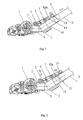
Fig. 1 shows an embodiment of the construction of a floor suction head for a vacuum cleaner in accordance with the present invention. -
Fig. 2 is a schematic diagram showing the joint status of the construction of the floor suction head shown inFig. 1 . -
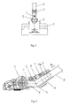
Fig. 3 is a top view showing the assembly of the floor suction head for the vacuum cleaner and the extension tube in accordance with the present invention. -
Fig. 4 is a schematic diagram showing the disassembly process of the floor suction head for the vacuum cleaner and the extension tube in accordance with the present invention. -
Fig. 5 is an integer perspective view of the vacuum cleaner in accordance with the present invention. - Hereinafter, the embodiment of the present invention will be described in details in reference to the drawings.
-
Fig. 1 shows an embodiment of the construction of a floor suction head for a vacuum cleaner in accordance with the present invention. In the present embodiment, the joint construction of the suction head for the vacuum cleaner comprises a floor suction head for collecting dusts on the floor, aconnecting tube 10 connected to the rear side of the floor suction head, and anextension tube 8 connected to the rear side of theconnecting tube 10. The floor suction head comprises asuction head body 1 provided at the foreside thereof and afloor suction arm 2 movably connected with thesuction head body 1, and the floor suction head is connected with the connectingtube 10 by the floorsuction head arm 2. Theextension tube 8 is connected to the rear side of the connectingtube 10, which is held by a user and moves the floor suction head on the floor surface for cleaning. - As shown in
Fig. 1 , theconnecting tube 10 is provided with a through hole 11 (a first joint section) at the joint portion of theconnecting tube 10 and theextension tube 8, and theextension tube 8 is provided with ajoint pin 9 at the joint of theextension tube 8 and the connecting tube; thejoint pin 9 is pressed outwards by an elastic force of a spring, a spring leaf or the like on the inner wall of the connectingtube 10. When theextension tube 8 is inserted into the connectingtube 10, thejoint pin 9 is pressed by the tube wall of the connectingtube 10, and thus theextension tube 8 is inserted. When thejoint pin 9 reaches the throughhole 11, it will bounce due to the elastic force; thus, the connectingtube 10 and theextension tube 8 are connected and fixed with each other by the interlocking of thejoint pin 9 and the throughhole 11. - In addition, in the present embodiment, there is a
joint release section 12 above the through hole 11 (and thejoint pin 9 interlocked with it) ; thejoint pin 9 can be press downwards by the use of therelease section 12 such that theextension tube 8 can be pulled out from theconnecting tube 10, thereby releasing the connection and the fix of theextension tube 8 and theconnecting tube 10.Fig. 2 shows a sectional view of the joint state. As long as the respective positions of thethrough hole 11 and thejoint pin 9 in theconnecting tube 10 and theextension tube 8 are properly arranged, an inserting length of theextension tube 8 into the connectingtube 10 can be determined. Further, the inner diameter of the connectingtube 10 and the outer diameter of theextension tube 8 can be properly set, such that the connectingtube 10 and theextension tube 8 can be firmly fixed by the interlocking of thejoint pin 9 and the throughhole 11. - The suction head for the vacuum cleaner needs to be cleaned and stored after use, and thus the connecting
tube 10 and theextension tube 8 need to be disconnected. Therefore, in order to improve the convenience of the disassembly operation, the vacuum cleaner of the present embodiment also comprises ajoint release section 12. Hereinafter, the construction of thejoint release section 12 is described in detail. - In the present embodiment, the
joint release section 12 is arranged substantially along with the longitudinal direction of the connectingtube 10 and covers the through hole 11 (and thejoint pin 9 connected with it). In addition, a supportingsection 13 is provided at one end of the longitudinal direction of the connectingtube 10, which is shaft supported at the external surface of the connectingtube 10, and anoperating section 5 is provided at the other end; aknock pin 12a, which protrudes towards the direction of the throughhole 11, is provided on the position corresponding to the throughhole 11. In accordance with the above embodiment, as shown inFig. 2 , theoperating section 5 is pressed downwards along the direction of arrow A, such that thejoint release section 12 rotates around the supportingsection 13 provided at the end thereof, thereby theknock pin 12a is inserted into the throughhole 11 towards the direction of the throughhole 11, which presses thejoint pin 9 downwards and releases the interlocking of the throughhole 11 and thejoint pin 9, and thus theextension tube 8 is pulled out from the connectingtube 10. - Further, the
joint release section 12 is provided with a spring 6 (an elastic device) for operational convenience. In the present embodiment, thespring 6 is arranged between the release section and theconnection tube 10, and which applies an elastic force between thejoint release section 12 and the connectingtube 10 to disconnect them. Under the elastic force of thespring 6, thejoint release section 12 lifts theknock pin 12a and theoperating section 5 with the supportingsection 13 being a pivot. In this status, theknock pin 12a leaves the throughhole 11 without applying any force to thejoint pin 9. The structure for limiting the lifting height of theoperating section 5 of thejoint release section 12 can be of any construction. For example, in the present embodiment, therelease section 12 is provided with a hole, and anut 7 which is fixed by penetrating the hole and screwing vertically into the side wall of the connectingtube 10; the lifting height of thejoint release section 12 can be limited by the tail flange of thenut 7 and the edge of the hole. Nevertheless, opposite hooks can be provided on thejoint release section 12 and the connectingtube 10, respectively; when thejoint release section 12 is lifted by thespring 6, the lifting height can be limited by the hitch of the terminal ends of said two hooks. - In the present embodiment,
Fig. 3 is a top view of the suction head for the vacuum cleaner of the present embodiment. In order to conveniently disassemble theextension tube 8 and theconnecting tube 10, theoperating section 5 is a footplate (hereinafter refer to as the footplate 5) arranged in the horizontal direction with increased width on both sides. As the width of thefootplate 5 exceeds the diameter of the connectingtube 10, the user can step downwards on thefootplate 5 with his foot after cleaning of floor, such that the knock pin of thejoint release section 12 presses against thejoint pin 9 to release the connection and the fix between theextension tube 8 and the connectingtube 10. As shown inFig. 4 , theextension tube 8 is pulled out along the direction of arrow B. - Further, in the present embodiment, as shown in
Figs. 1 and 2 , thefootplate 5 extends above the floor suction head, i.e., reaches the upside of the floorsuction head arm 2. Since the connectingtube 10 and the floor suction head arm are connected and fixed with each other, the angle between thefootplate 5 and the floorsuction head arm 2 is very small, and thereby the angle of thefootplate 5 in the horizontal direction can be reduced, which may facilitate the downward operation of thefootplate 5. - In addition, when a user steps on the
footplate 5 and theknock pin 12a releases the interlocking of the throughhole 11 and thejoint pin 9, the underside of thefootplate 5 is supported by the upper surface of the floor suction head (the floorsuction head arm 2 in the present embodiment). It can stabilize the operation of the user and avoid damage of thejoint pin 9 caused by over-insertion of theknock pin 12a into the through hole. - Further, when a user steps on the
footplate 5 and theknock pin 12a releases the interlocking of the throughhole 11 and thejoint pin 9, the underside of thefootplate 5 and the upper surface of the floor suction head (the floorsuction head arm 2 in the present embodiment) form arc-shapes which adapt with each other. Thus, the stress supporting range between thefootplate 5 and the floor suction head are increased during the disassembly operation, which can stabilize the operation of the user and avoid damage of thejoint release section 12 caused by concentrated stress. - In addition, the present invention also provides a vacuum cleaner using the joint construction of the suction head for the vacuum cleaner of the above invention. As shown in
Fig. 5 , the vacuum cleaner comprises a floor suction head, the above mentioned joint construction, ahose 20 connected with the extension tube, and acleaner body 30 connected to the end of thehose 20 for driving the vacuum cleaner. In accordance with above vacuum cleaner of the present invention, a user can disassemble the extension tube and the connecting tube of the floor suction head by simple operation, and thus enhance convenience.
Claims (7)
- A joint construction of a suction head for a vacuum cleaner, comprising:- a suction head body (1), a connecting tube (10) and an extension tube (8);- said connecting tube (10) connects in between the suction head body and the extension tube,- said connecting tube (10) is provided with a first joint section (11) at the joint of said connecting tube and said extension tube, for connecting and fixing said extension tube;- said extension tube (8) is provided with a second joint section (9) at the joint of said extension tube and said connecting tube, for interlocking with said first joint section to connect and fix said extension tube and said connecting tube;- a joint release section (12) for releasing the interlocking between said first and second joint sections is provided above said connecting tube and covers said first joint section; and- said joint release section (12) is arranged substantially along with the longitudinal direction of said connecting tube, with one end thereof provided with a supporting section which is shaft supported at the external surface of said connecting tube, and the other end thereof provided with an operating section (5) for operating the motion of said joint release section;characterized in that- said operating section (5) is arranged above said floor suction head arm (2), and when said operating section is operated downwards to release the interlocking of said first and second joint sections, said operating section is supported by said floor suction head arm.
- The joint construction of the suction head for the vacuum cleaner according to claim 1, characterized in that:said first joint section (11) is configured as a through hole provided on the upper tube wall of said connecting tube;said second joint section (9) is configured as a joint pin elastically protruding from the surface of said extension tube (8) and interlocked with said through hole;said joint release section (12) has a knock pin protruding towards said through hole of said first joint section and pressing said second joint section inward along the radial direction of said connecting tube (10).
- The joint construction of the suction head for the vacuum cleaner according to claim 1, characterized in that:said joint release section (12) has an elastic device (6) which can apply an elastic force between the tube wall of said connecting tube andsaid joint release section for disconnecting said joint release section from said first joint section (11).
- The joint construction of the suction head for the vacuum cleaner according to claim 1, characterized in that:the width of said operating section (5) on the horizontal direction is wider than the diameter of said connecting tube (10).
- The joint construction of the suction head for the vacuum cleaner according to claim 1, characterized in that:when said operating section (5) is operated downwards and is supported by said suction head body (1), contacting portions between the underside of said operating section and the upper surface of said suction head body are arc-shape corresponding with each other.
- The joint construction of the suction head for the vacuum cleaner according to any one of claims 1 to 4, characterized in that:said operating section (5) is preferably bilaterally symmetrical along the direction of said connecting tube (10).
- A vacuum cleaner, characterized by:having the joint construction of the suction head for the vacuum cleaner according to any one of claim 1 to 6.
Applications Claiming Priority (1)
| Application Number | Priority Date | Filing Date | Title |
|---|---|---|---|
| CNA2008101098177A CN101589932A (en) | 2008-05-30 | 2008-05-30 | Vacuum cleaner suction head connection structure and vacuum cleaner with the same structure |
Publications (3)
| Publication Number | Publication Date |
|---|---|
| EP2127583A2 EP2127583A2 (en) | 2009-12-02 |
| EP2127583A3 EP2127583A3 (en) | 2011-08-17 |
| EP2127583B1 true EP2127583B1 (en) | 2014-01-22 |
Family
ID=41011841
Family Applications (1)
| Application Number | Title | Priority Date | Filing Date |
|---|---|---|---|
| EP20090007024 Not-in-force EP2127583B1 (en) | 2008-05-30 | 2009-05-26 | Joint construction of suction head for vacuum cleaner and vacuum cleaner having the construction |
Country Status (2)
| Country | Link |
|---|---|
| EP (1) | EP2127583B1 (en) |
| CN (1) | CN101589932A (en) |
Families Citing this family (2)
| Publication number | Priority date | Publication date | Assignee | Title |
|---|---|---|---|---|
| USD1105672S1 (en) * | 2023-08-30 | 2025-12-09 | Sharkninja Operating Llc | Vacuum cleaner and vacuum nozzle |
| USD1068190S1 (en) * | 2024-07-05 | 2025-03-25 | Xiamen Nano Technology Co., Ltd | Cleaning head of vacuum cleaner |
Family Cites Families (4)
| Publication number | Priority date | Publication date | Assignee | Title |
|---|---|---|---|---|
| JPS60236191A (en) | 1984-05-08 | 1985-11-22 | Matsushita Electric Ind Co Ltd | semiconductor storage device |
| US4700429A (en) * | 1986-10-23 | 1987-10-20 | Whirlpool Corporation | Quick release wand for cannister vacuum cleaner |
| DE3942267C1 (en) * | 1989-12-21 | 1991-01-03 | Vorwerk & Co Interholding Gmbh, 5600 Wuppertal, De | |
| US7386917B2 (en) * | 2006-07-28 | 2008-06-17 | Panasonic Corporation Of North America | Vacuum cleaner with quick release wand |
-
2008
- 2008-05-30 CN CNA2008101098177A patent/CN101589932A/en active Pending
-
2009
- 2009-05-26 EP EP20090007024 patent/EP2127583B1/en not_active Not-in-force
Also Published As
| Publication number | Publication date |
|---|---|
| EP2127583A2 (en) | 2009-12-02 |
| CN101589932A (en) | 2009-12-02 |
| EP2127583A3 (en) | 2011-08-17 |
Similar Documents
| Publication | Publication Date | Title |
|---|---|---|
| US8438697B2 (en) | Vacuum cleaner | |
| US8720002B2 (en) | Handle assembly for a cleaning appliance | |
| AU2007283503B2 (en) | Handle assembly for a cleaning appliance | |
| US6079718A (en) | Golf club cart collapsing device | |
| CN102131428B (en) | Connector for coupling adjacent members | |
| US8292330B2 (en) | Insertable tube system for a vacuum cleaner | |
| EP2042403A3 (en) | Linkable dolly | |
| EP2127583A2 (en) | Joint construction of suction head for vacuum cleaner and vacuum cleaner having the construction | |
| KR20200012357A (en) | Apparatus for walking assistance | |
| JP2003069256A (en) | Eject mechanism for riser card | |
| US7676885B2 (en) | Carpet cleaner with pressed-down suction | |
| US7275279B2 (en) | Vacuum cleaner wand adapters and handle assemblies including the same | |
| CN204909309U (en) | Vacuum cleaner | |
| KR101493453B1 (en) | bidet possible of elevating and separating | |
| WO2013171618A1 (en) | Robotic vacuum cleaner with removable dust container | |
| JP2011136209A (en) | Vacuum cleaner | |
| KR101532682B1 (en) | Moving vehicle capable of mounting a dustcloth for cleaning | |
| CN223946373U (en) | Split type ultrasonic cleaner | |
| CN218907511U (en) | Push handle height adjusting device and scooter and jump rod with same | |
| CN213465322U (en) | Operation vehicle | |
| CN220423854U (en) | Multifunctional water squeezing mop | |
| JP2011024840A (en) | Suction nozzle of vacuum cleaner and vacuum cleaner using the same | |
| KR101043840B1 (en) | Vacuum cleaner | |
| CN207590609U (en) | A kind of connection structure and dust catcher | |
| US20140082870A1 (en) | Mop head retainer |
Legal Events
| Date | Code | Title | Description |
|---|---|---|---|
| PUAI | Public reference made under article 153(3) epc to a published international application that has entered the european phase |
Free format text: ORIGINAL CODE: 0009012 |
|
| AK | Designated contracting states |
Kind code of ref document: A2 Designated state(s): AT BE BG CH CY CZ DE DK EE ES FI FR GB GR HR HU IE IS IT LI LT LU LV MC MK MT NL NO PL PT RO SE SI SK TR |
|
| PUAL | Search report despatched |
Free format text: ORIGINAL CODE: 0009013 |
|
| AK | Designated contracting states |
Kind code of ref document: A3 Designated state(s): AT BE BG CH CY CZ DE DK EE ES FI FR GB GR HR HU IE IS IT LI LT LU LV MC MK MT NL NO PL PT RO SE SI SK TR |
|
| AX | Request for extension of the european patent |
Extension state: AL BA RS |
|
| RIC1 | Information provided on ipc code assigned before grant |
Ipc: A47L 9/24 20060101AFI20110711BHEP |
|
| 17P | Request for examination filed |
Effective date: 20120217 |
|
| 17Q | First examination report despatched |
Effective date: 20130416 |
|
| GRAP | Despatch of communication of intention to grant a patent |
Free format text: ORIGINAL CODE: EPIDOSNIGR1 |
|
| INTG | Intention to grant announced |
Effective date: 20130806 |
|
| GRAS | Grant fee paid |
Free format text: ORIGINAL CODE: EPIDOSNIGR3 |
|
| GRAA | (expected) grant |
Free format text: ORIGINAL CODE: 0009210 |
|
| AK | Designated contracting states |
Kind code of ref document: B1 Designated state(s): AT BE BG CH CY CZ DE DK EE ES FI FR GB GR HR HU IE IS IT LI LT LU LV MC MK MT NL NO PL PT RO SE SI SK TR |
|
| REG | Reference to a national code |
Ref country code: GB Ref legal event code: FG4D |
|
| REG | Reference to a national code |
Ref country code: CH Ref legal event code: EP |
|
| REG | Reference to a national code |
Ref country code: AT Ref legal event code: REF Ref document number: 650368 Country of ref document: AT Kind code of ref document: T Effective date: 20140215 |
|
| REG | Reference to a national code |
Ref country code: IE Ref legal event code: FG4D |
|
| REG | Reference to a national code |
Ref country code: DE Ref legal event code: R096 Ref document number: 602009021528 Country of ref document: DE Effective date: 20140306 |
|
| REG | Reference to a national code |
Ref country code: NL Ref legal event code: VDEP Effective date: 20140122 |
|
| REG | Reference to a national code |
Ref country code: AT Ref legal event code: MK05 Ref document number: 650368 Country of ref document: AT Kind code of ref document: T Effective date: 20140122 |
|
| REG | Reference to a national code |
Ref country code: LT Ref legal event code: MG4D |
|
| PG25 | Lapsed in a contracting state [announced via postgrant information from national office to epo] |
Ref country code: IS Free format text: LAPSE BECAUSE OF FAILURE TO SUBMIT A TRANSLATION OF THE DESCRIPTION OR TO PAY THE FEE WITHIN THE PRESCRIBED TIME-LIMIT Effective date: 20140522 Ref country code: NO Free format text: LAPSE BECAUSE OF FAILURE TO SUBMIT A TRANSLATION OF THE DESCRIPTION OR TO PAY THE FEE WITHIN THE PRESCRIBED TIME-LIMIT Effective date: 20140422 Ref country code: LT Free format text: LAPSE BECAUSE OF FAILURE TO SUBMIT A TRANSLATION OF THE DESCRIPTION OR TO PAY THE FEE WITHIN THE PRESCRIBED TIME-LIMIT Effective date: 20140122 |
|
| PG25 | Lapsed in a contracting state [announced via postgrant information from national office to epo] |
Ref country code: CY Free format text: LAPSE BECAUSE OF FAILURE TO SUBMIT A TRANSLATION OF THE DESCRIPTION OR TO PAY THE FEE WITHIN THE PRESCRIBED TIME-LIMIT Effective date: 20140122 Ref country code: SE Free format text: LAPSE BECAUSE OF FAILURE TO SUBMIT A TRANSLATION OF THE DESCRIPTION OR TO PAY THE FEE WITHIN THE PRESCRIBED TIME-LIMIT Effective date: 20140122 Ref country code: PT Free format text: LAPSE BECAUSE OF FAILURE TO SUBMIT A TRANSLATION OF THE DESCRIPTION OR TO PAY THE FEE WITHIN THE PRESCRIBED TIME-LIMIT Effective date: 20140522 Ref country code: NL Free format text: LAPSE BECAUSE OF FAILURE TO SUBMIT A TRANSLATION OF THE DESCRIPTION OR TO PAY THE FEE WITHIN THE PRESCRIBED TIME-LIMIT Effective date: 20140122 Ref country code: ES Free format text: LAPSE BECAUSE OF FAILURE TO SUBMIT A TRANSLATION OF THE DESCRIPTION OR TO PAY THE FEE WITHIN THE PRESCRIBED TIME-LIMIT Effective date: 20140122 Ref country code: FI Free format text: LAPSE BECAUSE OF FAILURE TO SUBMIT A TRANSLATION OF THE DESCRIPTION OR TO PAY THE FEE WITHIN THE PRESCRIBED TIME-LIMIT Effective date: 20140122 Ref country code: AT Free format text: LAPSE BECAUSE OF FAILURE TO SUBMIT A TRANSLATION OF THE DESCRIPTION OR TO PAY THE FEE WITHIN THE PRESCRIBED TIME-LIMIT Effective date: 20140122 |
|
| PG25 | Lapsed in a contracting state [announced via postgrant information from national office to epo] |
Ref country code: HR Free format text: LAPSE BECAUSE OF FAILURE TO SUBMIT A TRANSLATION OF THE DESCRIPTION OR TO PAY THE FEE WITHIN THE PRESCRIBED TIME-LIMIT Effective date: 20140122 Ref country code: LV Free format text: LAPSE BECAUSE OF FAILURE TO SUBMIT A TRANSLATION OF THE DESCRIPTION OR TO PAY THE FEE WITHIN THE PRESCRIBED TIME-LIMIT Effective date: 20140122 Ref country code: BE Free format text: LAPSE BECAUSE OF FAILURE TO SUBMIT A TRANSLATION OF THE DESCRIPTION OR TO PAY THE FEE WITHIN THE PRESCRIBED TIME-LIMIT Effective date: 20140122 |
|
| REG | Reference to a national code |
Ref country code: DE Ref legal event code: R097 Ref document number: 602009021528 Country of ref document: DE |
|
| PG25 | Lapsed in a contracting state [announced via postgrant information from national office to epo] |
Ref country code: CZ Free format text: LAPSE BECAUSE OF FAILURE TO SUBMIT A TRANSLATION OF THE DESCRIPTION OR TO PAY THE FEE WITHIN THE PRESCRIBED TIME-LIMIT Effective date: 20140122 Ref country code: RO Free format text: LAPSE BECAUSE OF FAILURE TO SUBMIT A TRANSLATION OF THE DESCRIPTION OR TO PAY THE FEE WITHIN THE PRESCRIBED TIME-LIMIT Effective date: 20140122 Ref country code: DK Free format text: LAPSE BECAUSE OF FAILURE TO SUBMIT A TRANSLATION OF THE DESCRIPTION OR TO PAY THE FEE WITHIN THE PRESCRIBED TIME-LIMIT Effective date: 20140122 Ref country code: EE Free format text: LAPSE BECAUSE OF FAILURE TO SUBMIT A TRANSLATION OF THE DESCRIPTION OR TO PAY THE FEE WITHIN THE PRESCRIBED TIME-LIMIT Effective date: 20140122 |
|
| PG25 | Lapsed in a contracting state [announced via postgrant information from national office to epo] |
Ref country code: PL Free format text: LAPSE BECAUSE OF FAILURE TO SUBMIT A TRANSLATION OF THE DESCRIPTION OR TO PAY THE FEE WITHIN THE PRESCRIBED TIME-LIMIT Effective date: 20140122 Ref country code: SK Free format text: LAPSE BECAUSE OF FAILURE TO SUBMIT A TRANSLATION OF THE DESCRIPTION OR TO PAY THE FEE WITHIN THE PRESCRIBED TIME-LIMIT Effective date: 20140122 |
|
| PLBE | No opposition filed within time limit |
Free format text: ORIGINAL CODE: 0009261 |
|
| STAA | Information on the status of an ep patent application or granted ep patent |
Free format text: STATUS: NO OPPOSITION FILED WITHIN TIME LIMIT |
|
| 26N | No opposition filed |
Effective date: 20141023 |
|
| PG25 | Lapsed in a contracting state [announced via postgrant information from national office to epo] |
Ref country code: LU Free format text: LAPSE BECAUSE OF FAILURE TO SUBMIT A TRANSLATION OF THE DESCRIPTION OR TO PAY THE FEE WITHIN THE PRESCRIBED TIME-LIMIT Effective date: 20140526 |
|
| REG | Reference to a national code |
Ref country code: CH Ref legal event code: PL |
|
| PG25 | Lapsed in a contracting state [announced via postgrant information from national office to epo] |
Ref country code: MC Free format text: LAPSE BECAUSE OF FAILURE TO SUBMIT A TRANSLATION OF THE DESCRIPTION OR TO PAY THE FEE WITHIN THE PRESCRIBED TIME-LIMIT Effective date: 20140122 Ref country code: LI Free format text: LAPSE BECAUSE OF NON-PAYMENT OF DUE FEES Effective date: 20140531 Ref country code: CH Free format text: LAPSE BECAUSE OF NON-PAYMENT OF DUE FEES Effective date: 20140531 |
|
| REG | Reference to a national code |
Ref country code: DE Ref legal event code: R097 Ref document number: 602009021528 Country of ref document: DE Effective date: 20141023 |
|
| REG | Reference to a national code |
Ref country code: IE Ref legal event code: MM4A |
|
| REG | Reference to a national code |
Ref country code: FR Ref legal event code: ST Effective date: 20150130 |
|
| PG25 | Lapsed in a contracting state [announced via postgrant information from national office to epo] |
Ref country code: IE Free format text: LAPSE BECAUSE OF NON-PAYMENT OF DUE FEES Effective date: 20140526 |
|
| PG25 | Lapsed in a contracting state [announced via postgrant information from national office to epo] |
Ref country code: FR Free format text: LAPSE BECAUSE OF NON-PAYMENT OF DUE FEES Effective date: 20140602 Ref country code: SI Free format text: LAPSE BECAUSE OF FAILURE TO SUBMIT A TRANSLATION OF THE DESCRIPTION OR TO PAY THE FEE WITHIN THE PRESCRIBED TIME-LIMIT Effective date: 20140122 |
|
| PG25 | Lapsed in a contracting state [announced via postgrant information from national office to epo] |
Ref country code: MT Free format text: LAPSE BECAUSE OF FAILURE TO SUBMIT A TRANSLATION OF THE DESCRIPTION OR TO PAY THE FEE WITHIN THE PRESCRIBED TIME-LIMIT Effective date: 20140122 |
|
| PG25 | Lapsed in a contracting state [announced via postgrant information from national office to epo] |
Ref country code: GR Free format text: LAPSE BECAUSE OF FAILURE TO SUBMIT A TRANSLATION OF THE DESCRIPTION OR TO PAY THE FEE WITHIN THE PRESCRIBED TIME-LIMIT Effective date: 20140423 Ref country code: IT Free format text: LAPSE BECAUSE OF FAILURE TO SUBMIT A TRANSLATION OF THE DESCRIPTION OR TO PAY THE FEE WITHIN THE PRESCRIBED TIME-LIMIT Effective date: 20140122 Ref country code: BG Free format text: LAPSE BECAUSE OF FAILURE TO SUBMIT A TRANSLATION OF THE DESCRIPTION OR TO PAY THE FEE WITHIN THE PRESCRIBED TIME-LIMIT Effective date: 20140122 |
|
| PG25 | Lapsed in a contracting state [announced via postgrant information from national office to epo] |
Ref country code: HU Free format text: LAPSE BECAUSE OF FAILURE TO SUBMIT A TRANSLATION OF THE DESCRIPTION OR TO PAY THE FEE WITHIN THE PRESCRIBED TIME-LIMIT; INVALID AB INITIO Effective date: 20090526 Ref country code: TR Free format text: LAPSE BECAUSE OF FAILURE TO SUBMIT A TRANSLATION OF THE DESCRIPTION OR TO PAY THE FEE WITHIN THE PRESCRIBED TIME-LIMIT Effective date: 20140122 |
|
| PG25 | Lapsed in a contracting state [announced via postgrant information from national office to epo] |
Ref country code: MK Free format text: LAPSE BECAUSE OF FAILURE TO SUBMIT A TRANSLATION OF THE DESCRIPTION OR TO PAY THE FEE WITHIN THE PRESCRIBED TIME-LIMIT Effective date: 20140122 |
|
| PGFP | Annual fee paid to national office [announced via postgrant information from national office to epo] |
Ref country code: GB Payment date: 20220425 Year of fee payment: 14 Ref country code: DE Payment date: 20220420 Year of fee payment: 14 |
|
| REG | Reference to a national code |
Ref country code: DE Ref legal event code: R119 Ref document number: 602009021528 Country of ref document: DE |
|
| GBPC | Gb: european patent ceased through non-payment of renewal fee |
Effective date: 20230526 |
|
| PG25 | Lapsed in a contracting state [announced via postgrant information from national office to epo] |
Ref country code: DE Free format text: LAPSE BECAUSE OF NON-PAYMENT OF DUE FEES Effective date: 20231201 Ref country code: GB Free format text: LAPSE BECAUSE OF NON-PAYMENT OF DUE FEES Effective date: 20230526 |