EP2126546B1 - Corrosion simulator and the corresponding method - Google Patents
Corrosion simulator and the corresponding method Download PDFInfo
- Publication number
- EP2126546B1 EP2126546B1 EP08723856.4A EP08723856A EP2126546B1 EP 2126546 B1 EP2126546 B1 EP 2126546B1 EP 08723856 A EP08723856 A EP 08723856A EP 2126546 B1 EP2126546 B1 EP 2126546B1
- Authority
- EP
- European Patent Office
- Prior art keywords
- test
- reactor vessel
- reactor
- fluid
- specimen
- Prior art date
- Legal status (The legal status is an assumption and is not a legal conclusion. Google has not performed a legal analysis and makes no representation as to the accuracy of the status listed.)
- Not-in-force
Links
- 238000005260 corrosion Methods 0.000 title claims description 30
- 230000007797 corrosion Effects 0.000 title claims description 30
- 238000000034 method Methods 0.000 title claims description 16
- 238000012360 testing method Methods 0.000 claims description 263
- 239000012530 fluid Substances 0.000 claims description 103
- 230000015556 catabolic process Effects 0.000 claims description 38
- 238000006731 degradation reaction Methods 0.000 claims description 38
- 238000006243 chemical reaction Methods 0.000 claims description 20
- 238000010438 heat treatment Methods 0.000 claims description 12
- 239000011521 glass Substances 0.000 claims description 5
- 238000003780 insertion Methods 0.000 claims description 5
- 230000037431 insertion Effects 0.000 claims description 5
- 239000010453 quartz Substances 0.000 claims description 5
- VYPSYNLAJGMNEJ-UHFFFAOYSA-N silicon dioxide Inorganic materials O=[Si]=O VYPSYNLAJGMNEJ-UHFFFAOYSA-N 0.000 claims description 5
- 238000005303 weighing Methods 0.000 claims description 3
- 238000001514 detection method Methods 0.000 claims description 2
- 239000007769 metal material Substances 0.000 claims description 2
- 239000007795 chemical reaction product Substances 0.000 claims 1
- 239000000463 material Substances 0.000 description 8
- 239000002184 metal Substances 0.000 description 8
- 229910052751 metal Inorganic materials 0.000 description 8
- 239000003921 oil Substances 0.000 description 8
- 238000001816 cooling Methods 0.000 description 7
- 239000010779 crude oil Substances 0.000 description 7
- 238000009533 lab test Methods 0.000 description 6
- 239000000203 mixture Substances 0.000 description 5
- IJGRMHOSHXDMSA-UHFFFAOYSA-N Atomic nitrogen Chemical compound N#N IJGRMHOSHXDMSA-UHFFFAOYSA-N 0.000 description 4
- XLYOFNOQVPJJNP-UHFFFAOYSA-N water Substances O XLYOFNOQVPJJNP-UHFFFAOYSA-N 0.000 description 4
- 239000003112 inhibitor Substances 0.000 description 3
- 150000003839 salts Chemical class 0.000 description 3
- 238000005336 cracking Methods 0.000 description 2
- 230000000694 effects Effects 0.000 description 2
- VNWKTOKETHGBQD-UHFFFAOYSA-N methane Chemical compound C VNWKTOKETHGBQD-UHFFFAOYSA-N 0.000 description 2
- 229910052757 nitrogen Inorganic materials 0.000 description 2
- 239000002699 waste material Substances 0.000 description 2
- CWYNVVGOOAEACU-UHFFFAOYSA-N Fe2+ Chemical compound [Fe+2] CWYNVVGOOAEACU-UHFFFAOYSA-N 0.000 description 1
- 238000013459 approach Methods 0.000 description 1
- 230000000712 assembly Effects 0.000 description 1
- 238000000429 assembly Methods 0.000 description 1
- 238000005452 bending Methods 0.000 description 1
- 238000004090 dissolution Methods 0.000 description 1
- 238000004821 distillation Methods 0.000 description 1
- 230000004907 flux Effects 0.000 description 1
- 239000007788 liquid Substances 0.000 description 1
- 238000012423 maintenance Methods 0.000 description 1
- 238000005259 measurement Methods 0.000 description 1
- 150000002739 metals Chemical class 0.000 description 1
- 239000003345 natural gas Substances 0.000 description 1
- 229920000642 polymer Polymers 0.000 description 1
- 238000010926 purge Methods 0.000 description 1
- 239000000523 sample Substances 0.000 description 1
- 239000002689 soil Substances 0.000 description 1
- 239000000758 substrate Substances 0.000 description 1
- 230000008961 swelling Effects 0.000 description 1
Images



Classifications
-
- G—PHYSICS
- G01—MEASURING; TESTING
- G01N—INVESTIGATING OR ANALYSING MATERIALS BY DETERMINING THEIR CHEMICAL OR PHYSICAL PROPERTIES
- G01N17/00—Investigating resistance of materials to the weather, to corrosion, or to light
- G01N17/002—Test chambers
Definitions
- the invention relates to a laboratory degradation test system according to the preamble of claim 1 and to a method for degradation testing.
- US 5,503,006 discloses a high temperature corrosion simulator.
- This known corrosion simulator comprises a reactor vessel or an array of reactor vessels which can be arranged in series. In such a reactor vessel, a corrosion coupon or a different kind of corrosion probe can be introduced. Through the reactor vessel or reactor vessels, a high temperature test fluid, which is at least suspected to induce corrosion, is circulated.
- the simulator further comprises a plug for influencing the flow pattern of the test fluid through the reactor vessel.
- a plug can be provided with a heat exchanger.
- US2005/076707 pertains to devices for the testing of the effect of liquids on one or more flat materials.
- the device comprises a first plate having a plurality of recesses; a second plate for engaging the first alate, wherein the first and second plates are adapted to receive at least one substrate for testing therebetween, the plates defining a plurality of chambers: a drive for moving the first and second plates: and heating means, for increasing the temperature in the chambers.
- the test fluid remains heated and remains in the recess for the entire duration of the test.
- test fluid is kept at a high temperature throughout the entire execution of the test.
- Many relevant test fluids such as crude oil or fractions thereof, tend to respond to this by a change in properties, which change has an undesired effect on the test results.
- the object of the invention is to provide an improved laboratory degradation test system and an improved method for degradation testing.
- the test system according to the invention is characterised in that the volume available to the test fluid in the reaction space after insertion of the degradation test specimen is less than or equal to 10 ml.
- a small volume of test fluid responds faster to heating than a larger volume of test fluid.
- the test fluid When the test fluid leaves the reactor vessel, it re-enters the circulation line at a temperature that is more or less equal to the reaction temperature. Due to the small volume of the heated test fluid, the temperature of the test fluid that was heated by the reactor vessel drops relatively quickly to the circulation temperature without the need for additional active cooling. So, in general no additional technical provisions for cooling the test fluid after it has left the reactor vessel, such as providing a cooling unit, have to be made. Due to the small heated volume and the rapid cooling, the circulation temperature will be substantially equal to the volume based average temperature of the test fluid in the circulation system, if no further heating or cooling takes place in the circulation system.
- the volume available to the test fluid inside the reaction space after insertion of the degradation test specimen is less than or equal to 10%, more preferably less than or equal to 5%, of the total the volume available to the test fluid in the reactor vessel assembly and the circulation system together.
- the flow rate of the test fluid in the circulation line is kept low, preferably less than 10 ml/min, more preferably less than or equal to 1 ml/min.
- the residence time of the test fluid in the reactor vessel can be relatively long. This allows effective heating of the test fluid by the reactor vessel.
- a small cross sectional area of the space inside the reaction space that is available to the test fluid can provide a suitable mass transport over the test specimen.
- the total volume available for the test fluid in the test system, more in particular in the reactor assembly and in the fluid circulation system together, is limited, preferably to 500 ml, more preferably to 50 ml.
- Such a small scale test system makes that a limited quantity of test fluid suffices for carrying out a degradation test. This is particularly advantageous when only a small quantity of test fluid is available, for example when the test fluid has to be obtained by a time consuming and/or energy consuming process. This is for example the case when the test fluid is a fraction of crude oil that has to be obtained by distillation.
- small scale test assemblies allow fast performance of many tests.
- the test system comprises a plurality of reactor vessels.
- a plurality of reactor vessels is arranged in parallel.
- the circulation line comprises an inlet manifold for distributing the total test fluid flow over the individual reactor vessels.
- a manifold may comprise a flow splitter, which for example comprises a plurality of capillary tubes or orifices.
- the circulation line also comprises an outlet manifold, which collects the test fluid leaving the individual reactor vessels in the circulation line.
- This embodiment allows parallel degradation tests to be carried out in a single test system. All reactor vessels will usually be fed with the same test fluid, but the test conditions in the individual reactor vessels may be varied. For example, different temperatures or pressures may exist in the different reactor vessels, or test specimens of different materials may be arranged in the different reactor vessels.
- an embodiment is envisaged in which a plurality of reactor vessels is arranged in series.
- an embodiment is envisaged in which not only a plurality of reactor vessels is provided, but also a plurality of circulation lines.
- Each circulation line can be associated with a single reactor vessel, but it is also envisaged that multiple reactor vessels are connected to a single circulation line.
- the use of a plurality of circulation lines allows the parallel use of different test fluids.
- the test system also comprises at least one reactor block, in which at least one reactor vessel can be arranged.
- the reactor block is a temperature controlled reactor block. In that case, the reactor block can be used to heat the reactor vessel or the reactor vessels that are present in the reactor block.
- the reactor vessel is made from a non-metallic material, for example quartz or glass. This is particularly advantageous in corrosion testing, because it avoids contact of the -often metallic- test specimen with an other metal object. Such metal-to-metal contact between two different metals may induce galvanic corrosion, which would influence the test results in an undesired way.
- a reactor block with glass or quartz reactor vessels according to WO02/092219 is used.
- a pressure control system according to WO2006/1071187 is used for controlling the pressure in de reactor vessel or reactor vessels.
- the specimen holder is adapted to hold a cylindrical test specimen, such as a test specimen in the form of a rod or wire or a hollow cylinder.
- a cylindrical test specimen such as a test specimen in the form of a rod or wire or a hollow cylinder.
- test specimens allow the use of small scale reactor vessels.
- the test fluid can be made to flow through the test specimen, around the test specimen or both.
- the specimen holder allows to impose a mechanical stress, for example a shear stress or tensile stress, on the test specimen.
- a shear stress can for example be imposed by twisting the one end of the test specimen relative to the other end.
- the specimen holder can then be adapted to maintain this twisted position of the test specimen during testing. This way, the occurrence stress corrosion cracking can be tested. This is particularly advantageous because it is hardly possible to predict the occurrence of stress corrosion cracking on the basis of a theoretical approach.
- the test system according to the invention can be used for corrosion testing.
- the corrosion resistance of a specific metal against a specific test fluid can be tested, if desired under specific process conditions.
- an embodiment is used that comprises a plurality of reactor vessels, in a short period of time much data can be gathered, for example by applying different process conditions in the different reactor vessels, by using test specimens of different materials and/or by applying different test fluids.
- the test system can also be used for testing the effectiveness of corrosion inhibitors.
- the test system can also be used for testing the degradation of non-metallic test specimens in relation to a specific environment. For example, the swelling of polymer test specimens in a specific test fluid can be tested. Also, the dissolution of components of materials is a specific environment can be tested.
- degradation analysis is performed.
- Such analysis can involve any known kind of relevant analysis.
- such degradation analysis can for example involve weighing of the test specimen before and after the test, measuring the electrical conductivity of the test specimen and/or of the test fluid, measuring the thermal conductivity of the test specimen, radiological testing, and/or measuring the concentration of corrosion products in the test fluid.
- crack detection such as eddy current analysis or magnaflux
- magnaflux can be used as an appropriate degradation analysis
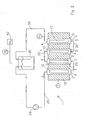
- Fig. 1 shows a first embodiment of a laboratory test system 1 according to the invention.
- Fig. 1 shows a reactor vessel 2, which has an inlet 3, an outlet 4 and a reaction space 5.
- the reactor vessel can be heated by heater 7.
- Heater 7 can be any kind of known heater for this purpose, like a heat exchanger or an electrical resistance wire, which is wound around the reactor vessel 2.
- the reactor vessel 2 can be heated by means of a temperature controlled reactor block, in which the reactor vessel 2 is arranged.
- the reactor vessel 2 is further provided with a test specimen holder 6 for retaining a degradation test specimen 10 in the reaction space.
- the test specimen holder can be any structure that retains a test specimen 10 in the reaction space.
- the test specimen holder can be for example a clamp that holds the test specimen, but also a filter or frit that prevents the test specimen from being dragged along by the test fluid.
- the test specimen holder can be a magnetic holder, being arranged either inside or outside the reactor vessel.
- the test system 1 further comprises a fluid circulation system that comprises a circulation line 20.
- a mechanical pump 25, driven by motor M is provided in the circulation line 20.
- an other type of pump can be provided, such as a thermosifon.
- a thermosifon has the advantage that it does not comprise moving parts so that it is less susceptible to wear and therefore needs less maintenance.
- the test system 1 also comprises a temperature controller T1 and a pressure controller P1.
- a degradation test specimen 10 is arranged in the test specimen holder 6.
- the test specimen can for example be a corrosion coupon.
- the test specimen 10 can in principle have any suitable shape. Corrosion coupons are usually flat, rectangular pieces of metal, but they can take any other suitable form as well, for example cylindrical.
- Reactor vessels generally have a cylindrical shape.
- the diameter of the test specimen can be chosen such that just a narrow space around the test specimen is present through which the test fluid can flow through the reaction space during testing.
- a combination of a cylindrical reactor vessel with an internal diameter of 2 mm with a test specimen having an outer diameter of 1.6 mm has in practice proven to be suitable.
- An other proven suitable combination is a cylindrical reactor vessel with an internal diameter of 4 mm with a cylindrical test specimen having and outer diameter of 3.4 mm.
- the required surface size can be obtained by choosing the length of the specimen. In practice, lengths of 5 cm (resulting in a surface size of 251 mm 2 for the 1.6 mm diameter specimen and of 534 mm 2 for the 3.4 mm diameter specimen) and 20 cm (resulting in a surface size of 1005 mm 2 for the 1.6 mm diameter specimen and of 2135 mm 2 for the 3.4 mm diameter specimen) have proven suitable.
- test fluid is introduced in the circulation line 20. This can be done in any suitable way. On introduction of the test fluid, the system is de-aerated.
- the test system is provided with a heater 7 for heating the reactor vessel 2. After filling the test system with the test fluid, the reactor vessel 2 is heated until it achieves the desired temperature. If it is desired to carry out the degradation test at an elevated pressure, a suitable pressurisation of the test system is carried out, for example using a source of nitrogen under pressure.
- Energising the pump 25 results in a circulation of test fluid through the circulation line 20 and the reactor vessel 2.
- the test fluid flows over the test specimen 10 in the longitudinal direction of the test specimen, so it is ensured that the entire surface of the test specimen 10 is in contact with the test fluid.
- the volume inside the reactor vessel 2 that is available to the test fluid is far smaller than the total volume available for the test fluid inside the test system.
- the total volume available to the test fluid can be about 20 to 25 ml, while the volume available to the test fluid in the reactor vessel 2 is 0.2 to 0.5 ml.
- the test fluid is heated by the reactor vessel 2 on passing through it. Because of the small volume of the test fluid inside the reactor vessel 2, a relatively small heat flux is sufficient to obtain a relatively large increase in temperature of the test fluid in the reactor vessel 2. With the parameters mentioned in the previous paragraph and in this paragraph, a temperature increase of a test fluid being crude oil or a fraction from 80°C in the circulation line to 300°C in the reactor vessel 2 has been obtained.
- test system 1 can be used at both elevated temperatures (up to 1050°C) and/or elevated pressures (up to 400 barg).
- test fluid As soon as the test fluid leaves the reactor vessel 2 via the outlet 4, the test fluid rapidly cools from the reaction temperature to the circulation temperature.
- the rapid cooling is due to the small volume of the test fluid that is heated by the reactor vessel. In general, additional means for forced cooling are not necessary.
- the test fluid can be any suitable medium such as H 2 , H 2 S, air, NH 3 , crude oil or fractions thereof, a mixture of oil and water, a mixture of oil and natural gas, a mixture of oil and steam, steam, salt steam, sour steam, HCl, salt water, a mixture of oil and salt water, condensate, an mixture of water and condensate and so on.
- suitable medium such as H 2 , H 2 S, air, NH 3 , crude oil or fractions thereof, a mixture of oil and water, a mixture of oil and natural gas, a mixture of oil and steam, steam, salt steam, sour steam, HCl, salt water, a mixture of oil and salt water, condensate, an mixture of water and condensate and so on.
- the test system 1 according to the invention can also be used to test the effectiveness of corrosion inhibitors. In that case, an appropriate quantity of corrosion inhibitor is added to the test fluid.
- test specimen 10 After contacting the test specimen 10 with the test fluid for the duration of the test, the test specimen can be subjected to further analysis, such as weighing or (electron)microscopic examination. During the test itself, analysis can be carried out too, for example by means of concentration measurements.
- test fluid is not circulated though the circulation line 20, but transferred from a source, via the reaction space to a waste vessel.
- Fig. 2 shows a second embodiment of the test system 1 according to the invention. This second embodiment is largely based on the embodiment of fig. 1 .
- a plurality of reactor vessels 2 is present.
- four reactor vessels 2 are provided.
- the reactor vessels 2 are arranged in a reactor block 15.
- the reactor block 15 is provided with temperature control T, so that by means of the reactor block 15, the temperature of the reactor vessels can be controlled.
- a reservoir 30 is present in the circulation system.
- a pressurised nitrogen source N2 provides a desired pressure in the reservoir.
- a pressure gauge P2 is provided.
- a reservoir of the type shown in the embodiment of fig. 2 can also be applied in the other described embodiments.
- the reactor vessels 2 are arranged in series. This way, several tests can be carried out simultaneously.
- a practical case in which it is advantageous to arrange the reactor vessels 2 in series is when a situation in a plant such as a refinery in which different types or materials are used for the equipment is to be simulated. In that case, test specimens of those different materials, in the order in which they are present in the plant as seem in the direction of the product flow, can be arranged in the reactor vessels 2.
- the circulation line 20 is divided into several parts: one part extending from the reservoir 30, via the pump 25 to the inlet 3 of the first reactor vessel 2, the parts between the outlet 4 of one reactor vessel 2 and the inlet 3 of the adjacent reactor vessel 2, and the part between the outlet 4 of the last reactor vessel 2 (as seen in the direction of the fluid flow).
- Pressure controller P1 is provide to control the pressure in the reactor vessels 2.
- Fig. 3 shows a third embodiment of the test system 1 according to the invention. This third embodiment is largely based on the embodiment of fig. 1 .
- a plurality of reactor vessels 2 is present.
- four reactor vessels 2 are provided.
- the reactor vessels 2 are arranged in parallel.
- each reactor vessel 2 is arranged in a separate reactor block 15.
- Each reactor block 15 is provided with a heater, for example in the form of channels through the reactor block through which a heating medium such as hot air or thermic oil can flow.
- the advantage of this set up is that each reactor vessel 2 can be given a different temperature, without influencing the temperature in the other reactor vessels.
- the temperature in the different reactor blocks 15 is controlled by separate temperature controllers T1, T2, T3, T4.
- a plurality of reactor vessels 2 is arranged in each reactor block 15.
- the circulation line 20 is provided with an inlet manifold 21.
- Outlet manifold 22 collects the test fluid form the reactor vessels 2 in the circulation line 20.
- a pressure control system P according to WO2006/107187 is used for controlling the pressure in the reactor vessels.
- connection point 35 the circulation line 20 is provided with a connection point 35.
- test fluid can be introduced into and/or evacuated from the test system 1.
- connection point is further provided with means for de-aerating and/or purging the test system 1.
- This connection point 35 can be of any suitable type, and can for example include a septum or a weldolet with a valve.
- a connection point of the type shown in the embodiment of fig. 3 can also be applied in the other described embodiments.
- an additional heater 23 is provided in the circulation line 20.
- This heater 23 can be used for maintaining a desired temperature of the test fluid in the circulation line. This is especially useful in case the test fluid has a high viscosity at room temperature, such as crude oil. When using crude oil as a test fluid, using heater 23 to maintain a circulation temperature of about 80°C in the circulation line has proven a suitable compromise between the viscosity and the risk of degradation of the oil.
- a heater 23 of the type shown in the embodiment of fig. 3 can also be applied in the other described embodiments.
- Fig. 4 shows a fourth embodiment of the test system 1 according to the invention.
- This fourth embodiment is largely based on the embodiment of fig. 1 and comprises a combination of embodiments similar to those of fig. 2 and fig. 3 .
- Fig. 5 shows a part of a fifth embodiment of a test system 1 according to the invention.
- a reactor block 15 with glass or quartz reactor vessels 2 according to WO02/092219 is used.
- the reactor block 15 has a cover 16 and seals 17, 18.
- additional channels 19 are provided in the reactor block 15 as shown in fig. 5 . These channels can be used to provide a pressure in the annular space between the wall of the reactor vessel and the wall of the recess of the reactor block that contains the reactor vessel 2, in order to prevent test fluid from entering this annular space. For example if crude oil is used as a test fluid, the oil in this annular space soils the system and can make the reactor vessel hard to remove from the reactor block. Also, such oil will degenerate due to the extended stay at high temperature.
- the additional channels can be used to dilute the reactor effluent, for example in order to speed up the removal of the reactor effluent from the reaction space.
- the wall of the reactor vessels 2 are arranged at a distance from the wall of the recess in the reactor block 15 in which the particular reactor vessel 2 is accommodated. Due to this distance, the pressure outside the reactor vessel 2 is the same as the pressure inside the reactor vessel 2. This allows the use of reactor vessels 2 of a relatively brittle material such as glass or quartz even for high pressure tests.
- Fig. 6 shows two exemplary embodiments of a specimen holder suitable for stress corrosion testing.
- a plug 60 with channels 61 is provided in the specimen holder 6 according to fig. 6A .
- the plug 60 can be arranged in a reactor vessel 2. The plug 60 is then kept in place by the friction between the wall of the reactor vessel 2 and the plug 60 itself. Channels 61 are provided to allow test fluid to pass by the plug 60.
- test specimen 10 in the form of a bend wire is arranged. By bending the test specimen 10, a tensile stress is induced upon the test specimen 10. Also non-wire shaped test specimens 10 can be bend and used in the specimen holder 6 of fig. 6A .
- two plugs 60, 62 are provided.
- the plugs 60,62 are provided with channels 61,63 for allowing the test fluid to pass by the plugs.
- test specimen 10 is twisted in order to introduce shear stress into the test specimen 10.
- Test specimens 10 of any shape, including rod-shaped or wire-shaped test specimens 10 can be twisted in order to obtain shear stress.
- test specimen holders 6 of the kind shown in fig. 6 is not limited to stress corrosion testing. Such specimen holders 6 can be used in any case wherein it is suspected that material stresses in the test specimen 10 are a factor of influence in the degradation behaviour.
Landscapes
- Life Sciences & Earth Sciences (AREA)
- Biodiversity & Conservation Biology (AREA)
- Ecology (AREA)
- Environmental & Geological Engineering (AREA)
- Environmental Sciences (AREA)
- Physics & Mathematics (AREA)
- Health & Medical Sciences (AREA)
- Chemical & Material Sciences (AREA)
- Analytical Chemistry (AREA)
- Biochemistry (AREA)
- General Health & Medical Sciences (AREA)
- General Physics & Mathematics (AREA)
- Immunology (AREA)
- Pathology (AREA)
- Testing Resistance To Weather, Investigating Materials By Mechanical Methods (AREA)
Description
- The invention relates to a laboratory degradation test system according to the preamble of
claim 1 and to a method for degradation testing. -
US 5,503,006 discloses a high temperature corrosion simulator. This known corrosion simulator comprises a reactor vessel or an array of reactor vessels which can be arranged in series. In such a reactor vessel, a corrosion coupon or a different kind of corrosion probe can be introduced. Through the reactor vessel or reactor vessels, a high temperature test fluid, which is at least suspected to induce corrosion, is circulated. The simulator further comprises a plug for influencing the flow pattern of the test fluid through the reactor vessel. Such a plug can be provided with a heat exchanger. -
US2005/076707 pertains to devices for the testing of the effect of liquids on one or more flat materials. In one embodiment, the device comprises a first plate having a plurality of recesses; a second plate for engaging the first alate, wherein the first and second plates are adapted to receive at least one substrate for testing therebetween, the plates defining a plurality of chambers: a drive for moving the first and second plates: and heating means, for increasing the temperature in the chambers. In these known devices, the test fluid remains heated and remains in the recess for the entire duration of the test. - The known corrosion simulator and method has the disadvantage that the test fluid is kept at a high temperature throughout the entire execution of the test. Many relevant test fluids, such as crude oil or fractions thereof, tend to respond to this by a change in properties, which change has an undesired effect on the test results.
- The object of the invention is to provide an improved laboratory degradation test system and an improved method for degradation testing.
- This object is achieved by the laboratory degradation test system according to
claim 1 and by the method for degradation testing of claim 8. - The test system according to the invention is characterised in that the volume available to the test fluid in the reaction space after insertion of the degradation test specimen is less than or equal to 10 ml. A small volume of test fluid responds faster to heating than a larger volume of test fluid. By limiting the volume of test fluid that can be contained in the reactor vessel, more in particular in the reaction space of the reactor vessel, heating the reactor vessel results in an effective heating of the test fluid that is present in the reactor vessel. This way, the general temperature in the circulation system at some distance from the outlet of the reactor vessel ("the circulation temperature") can be kept relatively low, while still a high temperature of the test fluid in the reactor vessel can be reached. The circulation temperature generally is about equal to the temperature at which the test fluid enters the reactor vessel, unless additional heating is applied in the circulation line.
- When the test fluid leaves the reactor vessel, it re-enters the circulation line at a temperature that is more or less equal to the reaction temperature. Due to the small volume of the heated test fluid, the temperature of the test fluid that was heated by the reactor vessel drops relatively quickly to the circulation temperature without the need for additional active cooling. So, in general no additional technical provisions for cooling the test fluid after it has left the reactor vessel, such as providing a cooling unit, have to be made. Due to the small heated volume and the rapid cooling, the circulation temperature will be substantially equal to the volume based average temperature of the test fluid in the circulation system, if no further heating or cooling takes place in the circulation system.
- In order to make use of this effectively, the volume available to the test fluid inside the reaction space after insertion of the degradation test specimen is less than or equal to 10%, more preferably less than or equal to 5%, of the total the volume available to the test fluid in the reactor vessel assembly and the circulation system together.
- In a possible embodiment, the flow rate of the test fluid in the circulation line is kept low, preferably less than 10 ml/min, more preferably less than or equal to 1 ml/min. By applying such a low flow rate of the test fluid, the residence time of the test fluid in the reactor vessel can be relatively long. This allows effective heating of the test fluid by the reactor vessel. A small cross sectional area of the space inside the reaction space that is available to the test fluid can provide a suitable mass transport over the test specimen.
- The total volume available for the test fluid in the test system, more in particular in the reactor assembly and in the fluid circulation system together, is limited, preferably to 500 ml, more preferably to 50 ml. Such a small scale test system makes that a limited quantity of test fluid suffices for carrying out a degradation test. This is particularly advantageous when only a small quantity of test fluid is available, for example when the test fluid has to be obtained by a time consuming and/or energy consuming process. This is for example the case when the test fluid is a fraction of crude oil that has to be obtained by distillation. Moreover, small scale test assemblies allow fast performance of many tests.
- It is envisaged that the test system comprises a plurality of reactor vessels. A number of possible embodiments is possible with this option. First, an embodiment is envisaged in which a plurality of reactor vessels is arranged in parallel. In that case, the circulation line comprises an inlet manifold for distributing the total test fluid flow over the individual reactor vessels. Such a manifold may comprise a flow splitter, which for example comprises a plurality of capillary tubes or orifices. In this embodiment, the circulation line also comprises an outlet manifold, which collects the test fluid leaving the individual reactor vessels in the circulation line. This embodiment allows parallel degradation tests to be carried out in a single test system. All reactor vessels will usually be fed with the same test fluid, but the test conditions in the individual reactor vessels may be varied. For example, different temperatures or pressures may exist in the different reactor vessels, or test specimens of different materials may be arranged in the different reactor vessels.
- Second, an embodiment is envisaged in which a plurality of reactor vessels is arranged in series.
- Third, an embodiment is envisaged in which not only a plurality of reactor vessels is provided, but also a plurality of circulation lines. Each circulation line can be associated with a single reactor vessel, but it is also envisaged that multiple reactor vessels are connected to a single circulation line. The use of a plurality of circulation lines allows the parallel use of different test fluids.
- In an advantageous embodiment, the test system also comprises at least one reactor block, in which at least one reactor vessel can be arranged. In a preferred embodiment, the reactor block is a temperature controlled reactor block. In that case, the reactor block can be used to heat the reactor vessel or the reactor vessels that are present in the reactor block.
- In an advantageous embodiment, the reactor vessel is made from a non-metallic material, for example quartz or glass. This is particularly advantageous in corrosion testing, because it avoids contact of the -often metallic- test specimen with an other metal object. Such metal-to-metal contact between two different metals may induce galvanic corrosion, which would influence the test results in an undesired way.
- In an advantageous embodiment, a reactor block with glass or quartz reactor vessels according to
WO02/092219 - In a further advantageous embodiment, a pressure control system according to
WO2006/1071187 - In an advantageous embodiment, the specimen holder is adapted to hold a cylindrical test specimen, such as a test specimen in the form of a rod or wire or a hollow cylinder. Such test specimens allow the use of small scale reactor vessels. In case of a hollow test specimen, the test fluid can be made to flow through the test specimen, around the test specimen or both.
- In a further possible embodiment, the specimen holder allows to impose a mechanical stress, for example a shear stress or tensile stress, on the test specimen. A shear stress can for example be imposed by twisting the one end of the test specimen relative to the other end. The specimen holder can then be adapted to maintain this twisted position of the test specimen during testing. This way, the occurrence stress corrosion cracking can be tested. This is particularly advantageous because it is hardly possible to predict the occurrence of stress corrosion cracking on the basis of a theoretical approach.
- The test system according to the invention can be used for corrosion testing. The corrosion resistance of a specific metal against a specific test fluid can be tested, if desired under specific process conditions. When an embodiment is used that comprises a plurality of reactor vessels, in a short period of time much data can be gathered, for example by applying different process conditions in the different reactor vessels, by using test specimens of different materials and/or by applying different test fluids.
- The test system can also be used for testing the effectiveness of corrosion inhibitors.
- The test system can also be used for testing the degradation of non-metallic test specimens in relation to a specific environment. For example, the swelling of polymer test specimens in a specific test fluid can be tested. Also, the dissolution of components of materials is a specific environment can be tested.
- After or during the contacting of the test specimen by the test fluid, degradation analysis is performed. Such analysis can involve any known kind of relevant analysis. In the case of testing for corrosion, such degradation analysis can for example involve weighing of the test specimen before and after the test, measuring the electrical conductivity of the test specimen and/or of the test fluid, measuring the thermal conductivity of the test specimen, radiological testing, and/or measuring the concentration of corrosion products in the test fluid.
- In the case of stress corrosion testing, crack detection, such as eddy current analysis or magnaflux, can be used as an appropriate degradation analysis,
- The invention will be described in more detail below under reference to the drawing, in which in a non-limiting manner exemplary embodiments of the invention will be shown.
- The drawing shows in:
- fig. 1
- - a first embodiment of a laboratory test system according to the invention,
- fig. 2
- - a second embodiment of a laboratory test system according to the invention,
- fig. 3
- - a third embodiment of a laboratory test system according to the invention,
- fig. 4
- - a fourth embodiment of a laboratory test system according to the invention,
- fig. 5
- - a part of a fifth embodiment of a laboratory test system according to the invention,
- fig. 6
- - exemplary embodiments of a specimen holder for stress corrosion testing.
-
Fig. 1 shows a first embodiment of alaboratory test system 1 according to the invention. -
Fig. 1 shows areactor vessel 2, which has aninlet 3, anoutlet 4 and areaction space 5. The reactor vessel can be heated byheater 7.Heater 7 can be any kind of known heater for this purpose, like a heat exchanger or an electrical resistance wire, which is wound around thereactor vessel 2. Alternatively, thereactor vessel 2 can be heated by means of a temperature controlled reactor block, in which thereactor vessel 2 is arranged. - The
reactor vessel 2 is further provided with atest specimen holder 6 for retaining adegradation test specimen 10 in the reaction space. The test specimen holder can be any structure that retains atest specimen 10 in the reaction space. The test specimen holder can be for example a clamp that holds the test specimen, but also a filter or frit that prevents the test specimen from being dragged along by the test fluid. In addition or as an alternative for retaining ferrous metal test specimens, the test specimen holder can be a magnetic holder, being arranged either inside or outside the reactor vessel. - The
test system 1 further comprises a fluid circulation system that comprises acirculation line 20. In this example, amechanical pump 25, driven by motor M, is provided in thecirculation line 20. Instead of a mechanical pump, also an other type of pump can be provided, such as a thermosifon. A thermosifon has the advantage that it does not comprise moving parts so that it is less susceptible to wear and therefore needs less maintenance. - The
test system 1 also comprises a temperature controller T1 and a pressure controller P1. - When using the embodiment of
fig. 1 for degradation testing, first adegradation test specimen 10 is arranged in thetest specimen holder 6. The test specimen can for example be a corrosion coupon. Thetest specimen 10 can in principle have any suitable shape. Corrosion coupons are usually flat, rectangular pieces of metal, but they can take any other suitable form as well, for example cylindrical. - In the test system according to the invention, it is advantageous to use elongated, slender cylindrical test specimens, for example rod-shaped or wire-shaped test specimens. Reactor vessels generally have a cylindrical shape. When a cylindrical test specimen is placed in the reactor vessel, the diameter of the test specimen can be chosen such that just a narrow space around the test specimen is present through which the test fluid can flow through the reaction space during testing.
- For example a combination of a cylindrical reactor vessel with an internal diameter of 2 mm with a test specimen having an outer diameter of 1.6 mm has in practice proven to be suitable. An other proven suitable combination is a cylindrical reactor vessel with an internal diameter of 4 mm with a cylindrical test specimen having and outer diameter of 3.4 mm.
- Degradation testing in general, and corrosion testing in particular, requires a certain size of the surface to be exposed to the test medium. With the sizes of the cylindrical test specimens as mentioned in the previous paragraph, the required surface size can be obtained by choosing the length of the specimen. In practice, lengths of 5 cm (resulting in a surface size of 251 mm2 for the 1.6 mm diameter specimen and of 534 mm2 for the 3.4 mm diameter specimen) and 20 cm (resulting in a surface size of 1005 mm2 for the 1.6 mm diameter specimen and of 2135 mm2 for the 3.4 mm diameter specimen) have proven suitable.
- When the
test specimen 10 has been inserted in thereactor vessel 2, the test fluid is introduced in thecirculation line 20. This can be done in any suitable way. On introduction of the test fluid, the system is de-aerated. - Usually, it will be necessary to carry out the degradation test at an elevated temperature. To that end, the test system is provided with a
heater 7 for heating thereactor vessel 2. After filling the test system with the test fluid, thereactor vessel 2 is heated until it achieves the desired temperature. If it is desired to carry out the degradation test at an elevated pressure, a suitable pressurisation of the test system is carried out, for example using a source of nitrogen under pressure. - Energising the
pump 25 results in a circulation of test fluid through thecirculation line 20 and thereactor vessel 2. The test fluid flows over thetest specimen 10 in the longitudinal direction of the test specimen, so it is ensured that the entire surface of thetest specimen 10 is in contact with the test fluid. - The volume inside the
reactor vessel 2 that is available to the test fluid is far smaller than the total volume available for the test fluid inside the test system. In a typical embodiment that has proven to be suitable in practice, the total volume available to the test fluid can be about 20 to 25 ml, while the volume available to the test fluid in thereactor vessel 2 is 0.2 to 0.5 ml. - Especially in combination with an small overall flow rate of for example 1 ml per minute, the test fluid is heated by the
reactor vessel 2 on passing through it. Because of the small volume of the test fluid inside thereactor vessel 2, a relatively small heat flux is sufficient to obtain a relatively large increase in temperature of the test fluid in thereactor vessel 2. With the parameters mentioned in the previous paragraph and in this paragraph, a temperature increase of a test fluid being crude oil or a fraction from 80°C in the circulation line to 300°C in thereactor vessel 2 has been obtained. - The
test system 1 according to the invention can be used at both elevated temperatures (up to 1050°C) and/or elevated pressures (up to 400 barg). - As soon as the test fluid leaves the
reactor vessel 2 via theoutlet 4, the test fluid rapidly cools from the reaction temperature to the circulation temperature. The rapid cooling is due to the small volume of the test fluid that is heated by the reactor vessel. In general, additional means for forced cooling are not necessary. - When the
test system 1 is used for corrosion testing, the test fluid can be any suitable medium such as H2, H2S, air, NH3, crude oil or fractions thereof, a mixture of oil and water, a mixture of oil and natural gas, a mixture of oil and steam, steam, salt steam, sour steam, HCl, salt water, a mixture of oil and salt water, condensate, an mixture of water and condensate and so on. - The
test system 1 according to the invention can also be used to test the effectiveness of corrosion inhibitors. In that case, an appropriate quantity of corrosion inhibitor is added to the test fluid. - After contacting the
test specimen 10 with the test fluid for the duration of the test, the test specimen can be subjected to further analysis, such as weighing or (electron)microscopic examination. During the test itself, analysis can be carried out too, for example by means of concentration measurements. - In a non-shown variant to
fig. 1 , the test fluid is not circulated though thecirculation line 20, but transferred from a source, via the reaction space to a waste vessel. -
Fig. 2 shows a second embodiment of thetest system 1 according to the invention. This second embodiment is largely based on the embodiment offig. 1 . - In the embodiment of
fig. 2 , a plurality ofreactor vessels 2 is present. In the example offig. 2 , fourreactor vessels 2 are provided. Thereactor vessels 2 are arranged in areactor block 15. In the embodiment offig. 2 , thereactor block 15 is provided with temperature control T, so that by means of thereactor block 15, the temperature of the reactor vessels can be controlled. - In the example of
fig. 2 , areservoir 30 is present in the circulation system. A pressurised nitrogen source N2 provides a desired pressure in the reservoir. To this end, a pressure gauge P2 is provided. A reservoir of the type shown in the embodiment offig. 2 can also be applied in the other described embodiments. - In the embodiment of
fig. 2 , thereactor vessels 2 are arranged in series. This way, several tests can be carried out simultaneously. A practical case in which it is advantageous to arrange thereactor vessels 2 in series is when a situation in a plant such as a refinery in which different types or materials are used for the equipment is to be simulated. In that case, test specimens of those different materials, in the order in which they are present in the plant as seem in the direction of the product flow, can be arranged in thereactor vessels 2. - In the embodiment of
fig. 2 , thecirculation line 20 is divided into several parts: one part extending from thereservoir 30, via thepump 25 to theinlet 3 of thefirst reactor vessel 2, the parts between theoutlet 4 of onereactor vessel 2 and theinlet 3 of theadjacent reactor vessel 2, and the part between theoutlet 4 of the last reactor vessel 2 (as seen in the direction of the fluid flow). - Pressure controller P1 is provide to control the pressure in the
reactor vessels 2. -
Fig. 3 shows a third embodiment of thetest system 1 according to the invention. This third embodiment is largely based on the embodiment offig. 1 . - In the embodiment of
fig. 3 , a plurality ofreactor vessels 2 is present. In the example offig. 3 , fourreactor vessels 2 are provided. In the embodiment offig. 3 , thereactor vessels 2 are arranged in parallel. - In the example of
fig. 3 , eachreactor vessel 2 is arranged in aseparate reactor block 15. Eachreactor block 15 is provided with a heater, for example in the form of channels through the reactor block through which a heating medium such as hot air or thermic oil can flow. The advantage of this set up is that eachreactor vessel 2 can be given a different temperature, without influencing the temperature in the other reactor vessels. The temperature in the different reactor blocks 15 is controlled by separate temperature controllers T1, T2, T3, T4. In a variant of this embodiment, a plurality ofreactor vessels 2 is arranged in eachreactor block 15. - In order to provide all
reactor vessels 2 with test fluid, thecirculation line 20 is provided with aninlet manifold 21.Outlet manifold 22 collects the test fluid form thereactor vessels 2 in thecirculation line 20. - In the embodiment of
fig. 3 , a pressure control system P according toWO2006/107187 is used for controlling the pressure in the reactor vessels. - In this example, the
circulation line 20 is provided with aconnection point 35. Through thisconnection point 35, test fluid can be introduced into and/or evacuated from thetest system 1. Preferably, the connection point is further provided with means for de-aerating and/or purging thetest system 1. Thisconnection point 35 can be of any suitable type, and can for example include a septum or a weldolet with a valve. A connection point of the type shown in the embodiment offig. 3 can also be applied in the other described embodiments. - In the example of
fig. 3 optionally anadditional heater 23 is provided in thecirculation line 20. Thisheater 23 can be used for maintaining a desired temperature of the test fluid in the circulation line. This is especially useful in case the test fluid has a high viscosity at room temperature, such as crude oil. When using crude oil as a test fluid, usingheater 23 to maintain a circulation temperature of about 80°C in the circulation line has proven a suitable compromise between the viscosity and the risk of degradation of the oil. Aheater 23 of the type shown in the embodiment offig. 3 can also be applied in the other described embodiments. -
Fig. 4 shows a fourth embodiment of thetest system 1 according to the invention. This fourth embodiment is largely based on the embodiment offig. 1 and comprises a combination of embodiments similar to those offig. 2 andfig. 3 . -
Fig. 5 shows a part of a fifth embodiment of atest system 1 according to the invention. - In the embodiment of
fig. 5 , areactor block 15 with glass orquartz reactor vessels 2 according toWO02/092219 reactor block 15 has acover 16 and seals 17, 18. As an optional feature,additional channels 19 are provided in thereactor block 15 as shown infig. 5 . These channels can be used to provide a pressure in the annular space between the wall of the reactor vessel and the wall of the recess of the reactor block that contains thereactor vessel 2, in order to prevent test fluid from entering this annular space. For example if crude oil is used as a test fluid, the oil in this annular space soils the system and can make the reactor vessel hard to remove from the reactor block. Also, such oil will degenerate due to the extended stay at high temperature. In a system without circulation, in which the test fluid flows from a source via the reactor vessel to a waste collector, the additional channels can be used to dilute the reactor effluent, for example in order to speed up the removal of the reactor effluent from the reaction space. - In the embodiment of
fig. 5 , the wall of thereactor vessels 2 are arranged at a distance from the wall of the recess in thereactor block 15 in which theparticular reactor vessel 2 is accommodated. Due to this distance, the pressure outside thereactor vessel 2 is the same as the pressure inside thereactor vessel 2. This allows the use ofreactor vessels 2 of a relatively brittle material such as glass or quartz even for high pressure tests. - For corrosion testing, it is advantageous to use
non-metallic reactor vessels 2, because this way metal-to-metal contact between thetest specimen 10 and thereactor vessel 2 is avoided. Such metal-to-metal contact could be the source of galvanic corrosion, which would influence the outcome of the corrosion tests in an undesirable way. -
Fig. 6 shows two exemplary embodiments of a specimen holder suitable for stress corrosion testing. - In the
specimen holder 6 according tofig. 6A , aplug 60 withchannels 61 is provided. Theplug 60 can be arranged in areactor vessel 2. Theplug 60 is then kept in place by the friction between the wall of thereactor vessel 2 and theplug 60 itself.Channels 61 are provided to allow test fluid to pass by theplug 60. - In the
specimen holder 6 according tofig. 6A atest specimen 10 in the form of a bend wire is arranged. By bending thetest specimen 10, a tensile stress is induced upon thetest specimen 10. Also non-wireshaped test specimens 10 can be bend and used in thespecimen holder 6 offig. 6A . - In the example of
fig. 6B , twoplugs plugs channels - In the
specimen holder 6 according tofig. 6B , thetest specimen 10 is twisted in order to introduce shear stress into thetest specimen 10.Test specimens 10 of any shape, including rod-shaped or wire-shapedtest specimens 10 can be twisted in order to obtain shear stress. - The use of
test specimen holders 6 of the kind shown infig. 6 is not limited to stress corrosion testing.Such specimen holders 6 can be used in any case wherein it is suspected that material stresses in thetest specimen 10 are a factor of influence in the degradation behaviour.
Claims (14)
- Laboratory degradation test system for testing degradation of a test specimen in a test fluid flow,
the test system comprising:- a reactor assembly, which reactor assembly comprises:- a reactor vessel (2), the reactor vessel (2) having a reaction space (5), an inlet (3) and an outlet (4) and a specimen holder (6) for retaining a test specimen (10) in the reaction space (5),- a heater (7) for heating the reactor vessel (2),- a fluid circulation system for generating a test fluid flow through the reactor vessel (2), to which flow the test specimen (10) is exposed, which fluid circulation system comprises:- a circulation line (20) which extends between the outlet of the reactor vessel (2) and the inlet of the reactor vessel (2), which circulation line (20) is arranged outside the reactor vessel (2),- a pump (25) for providing fluid circulation through the circulation line (20) and the reactor vessel (2), which pump (25) is arranged in the circulation line (20),- and a test specimen (10),characterised in that the volume available to the test fluid inside the reaction space (5) after insertion of the degradation test specimen (10) is less than or equal to 10 ml,
and in that the volume available to the test fluid inside the reaction space after insertion of the degradation test specimen (10) is less than or equal to 10% of the total volume available to the test fluid in the reactor vessel assembly and the circulation system together. - Degradation test system according to claim 1,
wherein the volume available to the test fluid inside the reaction space (5) after insertion of the degradation test specimen (10) is less than or equal to 5 ml, preferably less than or equal to 1 ml, and/or
wherein the volume available to the test fluid in the reactor vessel assembly and the circulation system together is less than or equal to 500 ml, preferably less than or equal to 50 ml. - Degradation test system according to any of the preceding claims,
wherein the test system comprises a plurality of reactor vessels (2) that are arranged in parallel, or,
wherein the test system comprises a plurality of reactor vessels (2) that are arranged in series. - Degradation test system according to any of the claims 1- 2,
wherein the test system comprises a plurality of reactor vessels (2), a plurality of circulation lines (20) and a plurality of pumps (25), each reactor vessel (2) being associated with a particular circulation line (20) and a particular pump (25), preferably the volume available to the test fluid inside a specific combination of a reactor vessel (2), its associated circulation line (20) and its associated pump (25) being less than or equal to 500 ml, said volume more preferably being less then or equal to 50 ml. - Degradation test system according to any of the preceding claims,
wherein the pump (25) is adapted to generate a flow rate of the test fluid of less than 10 ml/min, preferably a flow rate of less than or equal to 1 ml/min, and/or,
wherein the fluid circulation system further comprises a reservoir for holding a quantity of test fluid, and/or
wherein the test system further comprises a reactor block for accommodating at least one reactor vessel (2), wherein the reactor block preferably accommodates the heater (7) for heating the reactor vessel (2), and/or
wherein the reactor vessel (2) is made of a non-metallic material, preferably quartz or glass. - Degradation test system according to any of the preceding claims,
wherein the specimen holder (6) is adapted to retain an elongated cylindrical test specimen, preferably a slender, rod-shaped or wire-shaped test specimen, and/or
wherein the specimen holder (6) is adapted to hold the test specimen (10) under a mechanical stress, for example a shear stress or tensile stress, and/or
wherein the reaction space (5) is cylindrical and wherein the inlet of the reactor vessel (2) and the outlet of the reactor vessel (2) are arranged at opposed axial ends of the reaction space (5) and wherein a slender elongated test specimen is arranged axially in said reaction space (5). - Use of a test system according to any of the preceding claims for corrosion testing.
- Method for assessing degradation properties of a degradation test specimen in a test fluid flow, which method comprises the following steps:- providing a test system according to any of the claims 1-6,- arranging a degradation test specimen (10) in a specimen holder (6) and arranging said test specimen (10) inside the reactor vessel (2),- introducing a quantity of test fluid into the test system, the volume of the test fluid preferably being less than or equal to 500 ml,- heating the reactor vessel (2) to the test temperature,- energising the pump (25) during a period of time such that a test fluid flow is generated such that the test fluid flows over the surface of the test specimen (10),- performing a degradation analysis.
- Method according to claim 8,
wherein the degradation analysis includes at least one of weighing of the test specimen (10), measuring the concentration of reaction products in the test fluid, measuring the conductivity of the test fluid and/or the test specimen (10). - Method according to any of the claims 8-10,
wherein an apparatus is provided according to claim 1 wherein the test system further comprises a plurality of reactor vessels (2) that are arranged in parallel, or wherein the test system further comprises a plurality of reactor vessels (2), a plurality of circulation lines (20) and a plurality of pumps (25), each reactor vessel (2) being associated with a particular circulation line (20) and a particular pump (25), preferably the volume available to the test fluid inside a specific combination of a reactor vessel (2), its associated circulation line (20) and its associated pump (25) being less than or equal to 500 ml, said volume more preferably being less then or equal to 50 ml, and wherein at least one reactor vessel (2) is provided with a different temperature than an other reactor vessel (2). - Method according to any of the claims 8-10,
wherein an apparatus is provided according to claim 4, and wherein in at least one specific combination of a reactor vessel (2), its associated circulation line (20) and its associated pump (25) a different test fluid is introduced than in an other combination of a reactor vessel (2), its associated circulation line (20) and its associated pump (25). - Method according to any of the claims 8-11,
wherein the test fluid is preheated before entering the reactor vessel (2), and/or
wherein the flow rate of the test fluid is less than 10 ml/min, preferably less than or equal to 1 ml/min. - Method according to any of the claims 8-12.
wherein the circulation temperature of the test fluid is less than or equal to 200°C, preferably less than or equal to 100°C, more preferably less than or equal to 85°C, and/or,
wherein the temperature of the reactor vessel (2) is at least 250°C, and/or,
wherein the difference between the circulation temperature and the temperature of the reactor vessel (2) is at least 150°C, preferably at least 200°C. - Method according to any of the claims 8-13,
wherein a test system according to claim 1 is used wherein the specimen holder (6) is adapted to hold the test specimen (10) under a mechanical stress, for example a shear stress or tensile stress, and wherein the degradation analysis includes crack detection.
Priority Applications (1)
| Application Number | Priority Date | Filing Date | Title |
|---|---|---|---|
| EP08723856.4A EP2126546B1 (en) | 2007-03-19 | 2008-03-19 | Corrosion simulator and the corresponding method |
Applications Claiming Priority (3)
| Application Number | Priority Date | Filing Date | Title |
|---|---|---|---|
| EP07075209 | 2007-03-19 | ||
| PCT/NL2008/000084 WO2008115050A1 (en) | 2007-03-19 | 2008-03-19 | Corrosion simulator and the correspondence method |
| EP08723856.4A EP2126546B1 (en) | 2007-03-19 | 2008-03-19 | Corrosion simulator and the corresponding method |
Publications (2)
| Publication Number | Publication Date |
|---|---|
| EP2126546A1 EP2126546A1 (en) | 2009-12-02 |
| EP2126546B1 true EP2126546B1 (en) | 2014-12-24 |
Family
ID=38328962
Family Applications (1)
| Application Number | Title | Priority Date | Filing Date |
|---|---|---|---|
| EP08723856.4A Not-in-force EP2126546B1 (en) | 2007-03-19 | 2008-03-19 | Corrosion simulator and the corresponding method |
Country Status (4)
| Country | Link |
|---|---|
| US (1) | US8084267B2 (en) |
| EP (1) | EP2126546B1 (en) |
| BR (1) | BRPI0808218A2 (en) |
| WO (1) | WO2008115050A1 (en) |
Families Citing this family (7)
| Publication number | Priority date | Publication date | Assignee | Title |
|---|---|---|---|---|
| US8261601B2 (en) | 2008-12-12 | 2012-09-11 | Exxonmobil Upstream Research Company | Top of the line corrosion apparatus |
| WO2013107941A1 (en) * | 2012-01-20 | 2013-07-25 | Kemira Oyj | Device and method for monitoring biocide dosing in a machine |
| US10184869B2 (en) | 2013-10-15 | 2019-01-22 | Virtus Precision Tube, Llc | Apparatus and method for material testing |
| FR3014559B1 (en) * | 2013-12-05 | 2021-11-12 | Centre Detudes Et De Rech De Lindustrie Du Beton | SYSTEM AND METHOD FOR THE CHARACTERIZATION OF THE DEGRADATION OF A MATERIAL BY WASTEWATER |
| EP3032240B1 (en) * | 2014-12-11 | 2020-01-22 | Shell International Research Maatschappij B.V. | System and method for testing corrosive effect of a hydrocarbon on a component |
| WO2016123502A1 (en) * | 2015-01-30 | 2016-08-04 | Hydril USA Distribution LLC | Condition-based monitoring for materials in wellbore applications |
| EP3761005A1 (en) * | 2019-07-03 | 2021-01-06 | Cockerill Maintenance & Ingenierie S.A. | Dynamic test loop for determining molten salt corrosion |
Family Cites Families (6)
| Publication number | Priority date | Publication date | Assignee | Title |
|---|---|---|---|---|
| US4599217A (en) * | 1985-01-22 | 1986-07-08 | Exxon Chemical Patents Inc. | Corrosion simulator useful for heat exchangers condensing vapors containing water and method for using same |
| US4711131A (en) * | 1986-01-03 | 1987-12-08 | Mobil Oil Corporation | Method and apparatus for determining crack initiation and propagation in metals |
| US5503006A (en) * | 1993-08-31 | 1996-04-02 | Nalco Chemical Company | High temperature corrosion simulator |
| EP1256377A1 (en) | 2001-05-11 | 2002-11-13 | Avantium International B.V. | Apparatus, suitable for high throughput experimentation |
| DE10206620B4 (en) | 2002-02-15 | 2005-08-18 | Henkel Kgaa | Apparatus and method for simultaneous testing of the action of liquids on fabrics and use of the apparatus |
| BRPI0520513B1 (en) | 2005-04-04 | 2015-12-08 | Avantium Int Bv | system and method for conducting parallel chemical experiments |
-
2008
- 2008-03-19 WO PCT/NL2008/000084 patent/WO2008115050A1/en not_active Ceased
- 2008-03-19 EP EP08723856.4A patent/EP2126546B1/en not_active Not-in-force
- 2008-03-19 US US12/531,528 patent/US8084267B2/en not_active Expired - Fee Related
- 2008-03-19 BR BRPI0808218A patent/BRPI0808218A2/en not_active IP Right Cessation
Also Published As
| Publication number | Publication date |
|---|---|
| US20100105147A1 (en) | 2010-04-29 |
| US8084267B2 (en) | 2011-12-27 |
| EP2126546A1 (en) | 2009-12-02 |
| WO2008115050A1 (en) | 2008-09-25 |
| BRPI0808218A2 (en) | 2019-09-24 |
Similar Documents
| Publication | Publication Date | Title |
|---|---|---|
| US8084267B2 (en) | Corrosion simulator and corresponding method | |
| Singer et al. | Sour top-of-the-line corrosion in the presence of acetic acid | |
| US20070295099A1 (en) | Apparatus for forming thermal fatigue cracks | |
| Shetty et al. | Improved threshold fouling models for crude oils | |
| EP1789771B1 (en) | Process for simulating the corrosive effects of refinery feedstocks on refinery metallurgy | |
| CA1103953A (en) | Deposition test coupon | |
| CN102262020B (en) | Machine for testing tensile stress under high temperature & high pressure environments | |
| US20120074969A1 (en) | Coupon holder for corrosion measurement | |
| KR20220044729A (en) | Dynamic test loop to determine molten salt corrosion | |
| Kim et al. | Effects of mechanical vibration on critical heat flux in vertical annulus tube | |
| JP2008513760A5 (en) | ||
| US11378512B2 (en) | Corrosion process simulator | |
| GB1584377A (en) | Process and laboratory equipment for determining the thermal cracking behaviour of hydrocarbon feeds for cracking furnaces | |
| De Bruyn | Current corrosion monitoring trends in the petrochemical industry | |
| Frerichs et al. | Prediction of distortion of cylinders without phase transformations | |
| RU2433389C1 (en) | Method of determining thermal strains in cooled parts | |
| US6978663B1 (en) | Fouling test apparatus and process for evaluation of anti-foulants | |
| CN114279734A (en) | Pipe scale generation simulation device and pipe scale generation simulation method | |
| CN105181569A (en) | Ammonium salt under-scale corrosion experiment device and experiment method thereof | |
| Wold et al. | Solutions for corrosion monitoring in refineries | |
| CN2612946Y (en) | Probe for detecting phase transformation of pearlite type | |
| Turnbull et al. | Finite element analysis of the stress and strain associated with a corrosion pit in a cylindrical specimen under applied tensile loading. | |
| Azodi et al. | On the integrity of steam generator tubes and plugging assessment | |
| Velin | The effect of temperature on the zeta potential of magnetite particles in ammonia, morpholine and ethanolamine solutions | |
| Kapusňák et al. | Application of Metallography for the Slovak Nuclear Power Plants |
Legal Events
| Date | Code | Title | Description |
|---|---|---|---|
| PUAI | Public reference made under article 153(3) epc to a published international application that has entered the european phase |
Free format text: ORIGINAL CODE: 0009012 |
|
| 17P | Request for examination filed |
Effective date: 20090910 |
|
| AK | Designated contracting states |
Kind code of ref document: A1 Designated state(s): AT BE BG CH CY CZ DE DK EE ES FI FR GB GR HR HU IE IS IT LI LT LU LV MC MT NL NO PL PT RO SE SI SK TR |
|
| RIN1 | Information on inventor provided before grant (corrected) |
Inventor name: GRUTER, GERARDUS, JOHANNES, MARIA Inventor name: MOONEN, ROELANDUS, HENDRIKUS, WILHELMUS Inventor name: DE JONG, JAN, PETER Inventor name: KNOWLES, DAVID, MICHAEL |
|
| DAX | Request for extension of the european patent (deleted) | ||
| 17Q | First examination report despatched |
Effective date: 20131220 |
|
| GRAP | Despatch of communication of intention to grant a patent |
Free format text: ORIGINAL CODE: EPIDOSNIGR1 |
|
| INTG | Intention to grant announced |
Effective date: 20140626 |
|
| GRAP | Despatch of communication of intention to grant a patent |
Free format text: ORIGINAL CODE: EPIDOSNIGR1 |
|
| INTG | Intention to grant announced |
Effective date: 20140912 |
|
| GRAS | Grant fee paid |
Free format text: ORIGINAL CODE: EPIDOSNIGR3 |
|
| GRAA | (expected) grant |
Free format text: ORIGINAL CODE: 0009210 |
|
| AK | Designated contracting states |
Kind code of ref document: B1 Designated state(s): AT BE BG CH CY CZ DE DK EE ES FI FR GB GR HR HU IE IS IT LI LT LU LV MC MT NL NO PL PT RO SE SI SK TR |
|
| REG | Reference to a national code |
Ref country code: GB Ref legal event code: FG4D |
|
| REG | Reference to a national code |
Ref country code: CH Ref legal event code: EP |
|
| REG | Reference to a national code |
Ref country code: IE Ref legal event code: FG4D |
|
| REG | Reference to a national code |
Ref country code: AT Ref legal event code: REF Ref document number: 703396 Country of ref document: AT Kind code of ref document: T Effective date: 20150115 |
|
| REG | Reference to a national code |
Ref country code: DE Ref legal event code: R096 Ref document number: 602008036006 Country of ref document: DE Effective date: 20150212 |
|
| REG | Reference to a national code |
Ref country code: NL Ref legal event code: VDEP Effective date: 20141224 |
|
| PG25 | Lapsed in a contracting state [announced via postgrant information from national office to epo] |
Ref country code: FI Free format text: LAPSE BECAUSE OF FAILURE TO SUBMIT A TRANSLATION OF THE DESCRIPTION OR TO PAY THE FEE WITHIN THE PRESCRIBED TIME-LIMIT Effective date: 20141224 Ref country code: NO Free format text: LAPSE BECAUSE OF FAILURE TO SUBMIT A TRANSLATION OF THE DESCRIPTION OR TO PAY THE FEE WITHIN THE PRESCRIBED TIME-LIMIT Effective date: 20150324 Ref country code: LT Free format text: LAPSE BECAUSE OF FAILURE TO SUBMIT A TRANSLATION OF THE DESCRIPTION OR TO PAY THE FEE WITHIN THE PRESCRIBED TIME-LIMIT Effective date: 20141224 |
|
| REG | Reference to a national code |
Ref country code: LT Ref legal event code: MG4D |
|
| PG25 | Lapsed in a contracting state [announced via postgrant information from national office to epo] |
Ref country code: SE Free format text: LAPSE BECAUSE OF FAILURE TO SUBMIT A TRANSLATION OF THE DESCRIPTION OR TO PAY THE FEE WITHIN THE PRESCRIBED TIME-LIMIT Effective date: 20141224 Ref country code: LV Free format text: LAPSE BECAUSE OF FAILURE TO SUBMIT A TRANSLATION OF THE DESCRIPTION OR TO PAY THE FEE WITHIN THE PRESCRIBED TIME-LIMIT Effective date: 20141224 Ref country code: HR Free format text: LAPSE BECAUSE OF FAILURE TO SUBMIT A TRANSLATION OF THE DESCRIPTION OR TO PAY THE FEE WITHIN THE PRESCRIBED TIME-LIMIT Effective date: 20141224 Ref country code: GR Free format text: LAPSE BECAUSE OF FAILURE TO SUBMIT A TRANSLATION OF THE DESCRIPTION OR TO PAY THE FEE WITHIN THE PRESCRIBED TIME-LIMIT Effective date: 20150325 |
|
| REG | Reference to a national code |
Ref country code: AT Ref legal event code: MK05 Ref document number: 703396 Country of ref document: AT Kind code of ref document: T Effective date: 20141224 |
|
| PG25 | Lapsed in a contracting state [announced via postgrant information from national office to epo] |
Ref country code: NL Free format text: LAPSE BECAUSE OF FAILURE TO SUBMIT A TRANSLATION OF THE DESCRIPTION OR TO PAY THE FEE WITHIN THE PRESCRIBED TIME-LIMIT Effective date: 20141224 |
|
| PG25 | Lapsed in a contracting state [announced via postgrant information from national office to epo] |
Ref country code: RO Free format text: LAPSE BECAUSE OF FAILURE TO SUBMIT A TRANSLATION OF THE DESCRIPTION OR TO PAY THE FEE WITHIN THE PRESCRIBED TIME-LIMIT Effective date: 20141224 Ref country code: SK Free format text: LAPSE BECAUSE OF FAILURE TO SUBMIT A TRANSLATION OF THE DESCRIPTION OR TO PAY THE FEE WITHIN THE PRESCRIBED TIME-LIMIT Effective date: 20141224 Ref country code: EE Free format text: LAPSE BECAUSE OF FAILURE TO SUBMIT A TRANSLATION OF THE DESCRIPTION OR TO PAY THE FEE WITHIN THE PRESCRIBED TIME-LIMIT Effective date: 20141224 Ref country code: CZ Free format text: LAPSE BECAUSE OF FAILURE TO SUBMIT A TRANSLATION OF THE DESCRIPTION OR TO PAY THE FEE WITHIN THE PRESCRIBED TIME-LIMIT Effective date: 20141224 Ref country code: ES Free format text: LAPSE BECAUSE OF FAILURE TO SUBMIT A TRANSLATION OF THE DESCRIPTION OR TO PAY THE FEE WITHIN THE PRESCRIBED TIME-LIMIT Effective date: 20141224 |
|
| PG25 | Lapsed in a contracting state [announced via postgrant information from national office to epo] |
Ref country code: AT Free format text: LAPSE BECAUSE OF FAILURE TO SUBMIT A TRANSLATION OF THE DESCRIPTION OR TO PAY THE FEE WITHIN THE PRESCRIBED TIME-LIMIT Effective date: 20141224 Ref country code: IS Free format text: LAPSE BECAUSE OF FAILURE TO SUBMIT A TRANSLATION OF THE DESCRIPTION OR TO PAY THE FEE WITHIN THE PRESCRIBED TIME-LIMIT Effective date: 20150424 Ref country code: PL Free format text: LAPSE BECAUSE OF FAILURE TO SUBMIT A TRANSLATION OF THE DESCRIPTION OR TO PAY THE FEE WITHIN THE PRESCRIBED TIME-LIMIT Effective date: 20141224 |
|
| REG | Reference to a national code |
Ref country code: DE Ref legal event code: R097 Ref document number: 602008036006 Country of ref document: DE |
|
| REG | Reference to a national code |
Ref country code: DE Ref legal event code: R119 Ref document number: 602008036006 Country of ref document: DE |
|
| PG25 | Lapsed in a contracting state [announced via postgrant information from national office to epo] |
Ref country code: MC Free format text: LAPSE BECAUSE OF FAILURE TO SUBMIT A TRANSLATION OF THE DESCRIPTION OR TO PAY THE FEE WITHIN THE PRESCRIBED TIME-LIMIT Effective date: 20141224 Ref country code: LU Free format text: LAPSE BECAUSE OF FAILURE TO SUBMIT A TRANSLATION OF THE DESCRIPTION OR TO PAY THE FEE WITHIN THE PRESCRIBED TIME-LIMIT Effective date: 20150319 Ref country code: DK Free format text: LAPSE BECAUSE OF FAILURE TO SUBMIT A TRANSLATION OF THE DESCRIPTION OR TO PAY THE FEE WITHIN THE PRESCRIBED TIME-LIMIT Effective date: 20141224 |
|
| REG | Reference to a national code |
Ref country code: CH Ref legal event code: PL |
|
| PLBE | No opposition filed within time limit |
Free format text: ORIGINAL CODE: 0009261 |
|
| STAA | Information on the status of an ep patent application or granted ep patent |
Free format text: STATUS: NO OPPOSITION FILED WITHIN TIME LIMIT |
|
| GBPC | Gb: european patent ceased through non-payment of renewal fee |
Effective date: 20150324 |
|
| 26N | No opposition filed |
Effective date: 20150925 |
|
| PG25 | Lapsed in a contracting state [announced via postgrant information from national office to epo] |
Ref country code: IT Free format text: LAPSE BECAUSE OF FAILURE TO SUBMIT A TRANSLATION OF THE DESCRIPTION OR TO PAY THE FEE WITHIN THE PRESCRIBED TIME-LIMIT Effective date: 20141224 |
|
| REG | Reference to a national code |
Ref country code: FR Ref legal event code: ST Effective date: 20151130 |
|
| REG | Reference to a national code |
Ref country code: IE Ref legal event code: MM4A |
|
| PG25 | Lapsed in a contracting state [announced via postgrant information from national office to epo] |
Ref country code: GB Free format text: LAPSE BECAUSE OF NON-PAYMENT OF DUE FEES Effective date: 20150324 Ref country code: CH Free format text: LAPSE BECAUSE OF NON-PAYMENT OF DUE FEES Effective date: 20150331 Ref country code: IE Free format text: LAPSE BECAUSE OF NON-PAYMENT OF DUE FEES Effective date: 20150319 Ref country code: DE Free format text: LAPSE BECAUSE OF NON-PAYMENT OF DUE FEES Effective date: 20151001 Ref country code: LI Free format text: LAPSE BECAUSE OF NON-PAYMENT OF DUE FEES Effective date: 20150331 |
|
| PG25 | Lapsed in a contracting state [announced via postgrant information from national office to epo] |
Ref country code: SI Free format text: LAPSE BECAUSE OF FAILURE TO SUBMIT A TRANSLATION OF THE DESCRIPTION OR TO PAY THE FEE WITHIN THE PRESCRIBED TIME-LIMIT Effective date: 20141224 Ref country code: FR Free format text: LAPSE BECAUSE OF NON-PAYMENT OF DUE FEES Effective date: 20150331 |
|
| PG25 | Lapsed in a contracting state [announced via postgrant information from national office to epo] |
Ref country code: BE Free format text: LAPSE BECAUSE OF FAILURE TO SUBMIT A TRANSLATION OF THE DESCRIPTION OR TO PAY THE FEE WITHIN THE PRESCRIBED TIME-LIMIT Effective date: 20141224 |
|
| PG25 | Lapsed in a contracting state [announced via postgrant information from national office to epo] |
Ref country code: MT Free format text: LAPSE BECAUSE OF FAILURE TO SUBMIT A TRANSLATION OF THE DESCRIPTION OR TO PAY THE FEE WITHIN THE PRESCRIBED TIME-LIMIT Effective date: 20141224 |
|
| PG25 | Lapsed in a contracting state [announced via postgrant information from national office to epo] |
Ref country code: HU Free format text: LAPSE BECAUSE OF FAILURE TO SUBMIT A TRANSLATION OF THE DESCRIPTION OR TO PAY THE FEE WITHIN THE PRESCRIBED TIME-LIMIT; INVALID AB INITIO Effective date: 20080319 Ref country code: BG Free format text: LAPSE BECAUSE OF FAILURE TO SUBMIT A TRANSLATION OF THE DESCRIPTION OR TO PAY THE FEE WITHIN THE PRESCRIBED TIME-LIMIT Effective date: 20141224 |
|
| PG25 | Lapsed in a contracting state [announced via postgrant information from national office to epo] |
Ref country code: CY Free format text: LAPSE BECAUSE OF FAILURE TO SUBMIT A TRANSLATION OF THE DESCRIPTION OR TO PAY THE FEE WITHIN THE PRESCRIBED TIME-LIMIT Effective date: 20141224 |
|
| PG25 | Lapsed in a contracting state [announced via postgrant information from national office to epo] |
Ref country code: PT Free format text: LAPSE BECAUSE OF FAILURE TO SUBMIT A TRANSLATION OF THE DESCRIPTION OR TO PAY THE FEE WITHIN THE PRESCRIBED TIME-LIMIT Effective date: 20150424 |
|
| PG25 | Lapsed in a contracting state [announced via postgrant information from national office to epo] |
Ref country code: TR Free format text: LAPSE BECAUSE OF FAILURE TO SUBMIT A TRANSLATION OF THE DESCRIPTION OR TO PAY THE FEE WITHIN THE PRESCRIBED TIME-LIMIT Effective date: 20141224 |