EP2125520B1 - System for on-ground simulation of the ambient lighting conditions in the cockpit of an aircraft during flight - Google Patents
System for on-ground simulation of the ambient lighting conditions in the cockpit of an aircraft during flight Download PDFInfo
- Publication number
- EP2125520B1 EP2125520B1 EP07849384A EP07849384A EP2125520B1 EP 2125520 B1 EP2125520 B1 EP 2125520B1 EP 07849384 A EP07849384 A EP 07849384A EP 07849384 A EP07849384 A EP 07849384A EP 2125520 B1 EP2125520 B1 EP 2125520B1
- Authority
- EP
- European Patent Office
- Prior art keywords
- dome
- cockpit
- light
- aircraft
- panels
- Prior art date
- Legal status (The legal status is an assumption and is not a legal conclusion. Google has not performed a legal analysis and makes no representation as to the accuracy of the status listed.)
- Not-in-force
Links
Images


Classifications
-
- F—MECHANICAL ENGINEERING; LIGHTING; HEATING; WEAPONS; BLASTING
- F21—LIGHTING
- F21S—NON-PORTABLE LIGHTING DEVICES; SYSTEMS THEREOF; VEHICLE LIGHTING DEVICES SPECIALLY ADAPTED FOR VEHICLE EXTERIORS
- F21S8/00—Lighting devices intended for fixed installation
- F21S8/006—Solar simulators, e.g. for testing photovoltaic panels
-
- B—PERFORMING OPERATIONS; TRANSPORTING
- B64—AIRCRAFT; AVIATION; COSMONAUTICS
- B64F—GROUND OR AIRCRAFT-CARRIER-DECK INSTALLATIONS SPECIALLY ADAPTED FOR USE IN CONNECTION WITH AIRCRAFT; DESIGNING, MANUFACTURING, ASSEMBLING, CLEANING, MAINTAINING OR REPAIRING AIRCRAFT, NOT OTHERWISE PROVIDED FOR; HANDLING, TRANSPORTING, TESTING OR INSPECTING AIRCRAFT COMPONENTS, NOT OTHERWISE PROVIDED FOR
- B64F5/00—Designing, manufacturing, assembling, cleaning, maintaining or repairing aircraft, not otherwise provided for; Handling, transporting, testing or inspecting aircraft components, not otherwise provided for
- B64F5/60—Testing or inspecting aircraft components or systems
-
- F—MECHANICAL ENGINEERING; LIGHTING; HEATING; WEAPONS; BLASTING
- F21—LIGHTING
- F21V—FUNCTIONAL FEATURES OR DETAILS OF LIGHTING DEVICES OR SYSTEMS THEREOF; STRUCTURAL COMBINATIONS OF LIGHTING DEVICES WITH OTHER ARTICLES, NOT OTHERWISE PROVIDED FOR
- F21V14/00—Controlling the distribution of the light emitted by adjustment of elements
- F21V14/02—Controlling the distribution of the light emitted by adjustment of elements by movement of light sources
Definitions
- the present invention relates to an on-ground simulation system able to recreate artificially, in a special environment which is capable of housing an entire aircraft or at least its cockpit, the natural lighting conditions which this aircraft may encounter during its operational use.
- the cockpit of a modem aircraft has a plurality of instruments and displays which provide the pilot with all the necessary information.
- unfavourable static or dynamic light conditions may occur and create critical situations associated with the poor visibility in particular of the displays (for example of the LCD and CRT type) which are greatly influenced by the direction of the light and the contrast conditions.
- Difficult lighting conditions occur, for example, in the following cases: direct sunlight or sunlight which is reflected on the displays as a result of the sun being situated at the rear or on the side of the cockpit; very bright dazzling light reflected by the clouds; changing lighting conditions at dawn or sunset, when the sun is situated close to the horizon and cockpit which is illuminated with night-time lighting.
- Night-time flying may also give rise to critical conditions if image intensifiers ("night vision goggles”) are in use, since they require a suitable emission spectrum and a given brightness level of the lighting inside the cockpit.
- the pilot must always have a good visibility of the on-board instruments in any external lighting conditions and must also be able to see outside without interference from the light sources inside the cockpit which could dazzle the pilot directly or as a result of reflection on the transparent canopy.
- US-A-3 321 620 discloses a solar simulator where compliance with radiation and not lighting levels is tested - comprising such a dome and a light emitting panel.
- DE 100 45 028 A1 discloses a light emitting panel disposed above a motor vehicle.
- the intermediate document FR-A-2 898 586 discloses a device for assisting in the design of an aircraft flight deck compatible with a night vision system, whereby a mockup of an aircraft cockpit is placed in a darkroom and a single light source can be moved around in the darkroom.
- the object of the invention is to overcome the drawbacks mentioned above and in particular to simulate on the ground in a repeatable, reliable, certain and economical manner the lighting environment to which the equipment inside the cockpit is exposed during flying, in order to optimise the choice as to the type and position of light sources present therein (displays, luminous panels and luminous sources in general).
- a system according to the invention comprises a mesh-like metallic structure 12 with a hemispherical dome, the inner vault or covering of which consists of an ordered arrangement of light-emitting panels 10 and reflective panels 11 which have the function of reproducing artificially a diffused light condition in the sky, as described more clearly below.
- the sky is not regarded as a continuous surface, but is reproduced discretely by a given number of polygonal panels.
- the dome has an internal diameter of 12 m so as to be able to house the front part of the fuselage of a small-size aircraft A or a medium-size transportation aircraft.
- the dome may be equally well formed as a hemisphere which extends underneath the horizon line through at least 24° or (as in the embodiment shown in the drawings) as a hemisphere mounted on top of a vertical cylindrical drum 13 having the same radius as the dome and being lined internally with light-emitting panels 10 and/or reflective panels 11.
- the surface of the dome is interrupted by an opening 14 for allowing the entry of the front part of the fuselage of the aircraft being tested.
- a rail-type movement system (not shown) allows the aircraft to be towed inside the dome, positioning the cockpit in the centre thereof.
- the opening 14 is then sealed by curtains or screens 15 which isolate the internal lit environment from the external environment.
- the lighting conditions inside the dome must be able to be completely controlled artificially and not be affected by (chinks of) light entering from outside.
- the light-emitting panels 10 are lit with the possibility of adjusting their intensity, or switched off, depending on the lighting conditions which are to be created and for which it is required to verify the "readability" of the on-board instrumentation and the simultaneous possibility of the pilot being able to see outside.
- the light-emitting panels 10 are preferably concentrated in the front and rear zone of the dome in an arrangement distributed in the manner of lunes. This configuration ensures that the panels 10, when lit, give rise to one of the visibility conditions considered to be most critical for the pilot: dazzling effect due to a lot of light from the front; and mirror-like reflection on the instrument displays of the light from behind. This condition is, for example, useful for evaluating the use of certain types of display, the information on which is poorly visible when the surrounding light is particularly strong. As an alternative to the example shown, the light-emitting panels 10 may line the whole of the inside of the dome.
- the light-emitting panels 10 may contain equally well fluorescent tubes, or LED arrays, or light sources of another kind, the luminous intensity of which may be modulated with different voltage levels so as to emit more or less light with a view to recreating artificially, in a selective manner, lighting conditions representing some particularly critical conditions which the pilot may encounter whilst flying.
- the fluorescent tubes are covered by a diffusing screen which ensures the uniformity of the light emitted by each panel.
- the switching-on and modulation of each light-emitting panel or each subassembly of light sources forming a panel is controlled individually by software which allows suitable mapping of various sky illumination models.
- the light-emitting or reflective panels which line the cylindrical drum 13 at the base of the dome have the function of recreating another critical visibility situation, where the aircraft is situated above a blanket of clouds while the sky above is clear with radiant sunshine. This is a "saturation" light condition where the panels in the base drum simulate the layer of clouds which reflect the sunlight.
- a powerful directable floodlight 16 (for example with a power of 12 kW) has the function of simulating the direct light from the sun.
- the floodlight 16 is designed to have the same apparent size as the round ball of sun viewed from the cockpit which is situated in the centre of the dome and is able to concentrate the light onto the cockpit and provide a lighting strength of at least 150,000 lux in the centre of the dome.
- the floodlight 16 is mounted on an articulated curved arm 17, the base of which is able to travel along a curved rail 18 situated at the bottom of the dome.
- the azimuth and height of the articulated arm 17 are adjustable so as to arrange the floodlight or "sun" 16 virtually in any position around or above the cockpit and in any case in the most critical positions as regards visibility.
- the "sun" 16 is situated directly in front on the horizon; in Figure 7 it is inclined at 30° at the rear of the aircraft and in Figure 8 it is situated at its highest point.
- the position of the floodlight 16 which can be directed so as to project onto the cockpit a beam of light which simulates the direct sunlight and, if necessary, by adjusting the light-emitting panels 10 depending on the conditions which are to be recreated, it is possible to verify the visibility of the on-board instruments virtually in any condition.
- the system may envisage a pair of floodlights (not shown) which illuminate a reflective panel (not shown) situated in front of the pilot.
- This has the function of simulating a dazzling condition due to the diffused light of surrounding clouds, with particular attention to the field of vision of the pilot during reading of the symbols which appear on the display, for example on the HUD.
- the system according to the present invention is moreover equipped with:
- the present invention provides the possibility of performing test activities, without having to take into account the weather conditions (which may instead hinder execution of in-flight tests). Moreover, with the system it is possible to reproduce, on the ground, lighting conditions which are required by the regulations for certification of the aircraft and which are difficult to achieve during flights.
- the simulation system By simulating on the ground in a repeatable and reliable manner the lighting environment to which the equipment is operationally exposed during flying, the simulation system allows the on-ground design and testing of the visual interface, reducing the costs and the risks associated with in-flight testing activities.
- the system is able to house internally not only simulated cockpits of almost any size (therefore constituting a valid tool during design and testing of the visual interface of any new aircraft), but also the fuselage part containing the cockpit of aircraft of varying sizes, including those with medium-size bodies (such as the B737), therefore also providing a valid tool for testing and validating, on the ground, modifications made to already existing aircraft or aircraft in the advanced stage of design.
- system according to the present invention may be used for test activities in connection with the following:
Landscapes
- Engineering & Computer Science (AREA)
- General Engineering & Computer Science (AREA)
- Aviation & Aerospace Engineering (AREA)
- Sustainable Development (AREA)
- Manufacturing & Machinery (AREA)
- Transportation (AREA)
- Life Sciences & Earth Sciences (AREA)
- Traffic Control Systems (AREA)
- Illuminated Signs And Luminous Advertising (AREA)
- Non-Portable Lighting Devices Or Systems Thereof (AREA)
- Circuit Arrangement For Electric Light Sources In General (AREA)
- Management, Administration, Business Operations System, And Electronic Commerce (AREA)
- Ventilation (AREA)
- Testing And Monitoring For Control Systems (AREA)
Abstract
Description
- The present invention relates to an on-ground simulation system able to recreate artificially, in a special environment which is capable of housing an entire aircraft or at least its cockpit, the natural lighting conditions which this aircraft may encounter during its operational use.
- The cockpit of a modem aircraft has a plurality of instruments and displays which provide the pilot with all the necessary information. During daytime flying, unfavourable static or dynamic light conditions may occur and create critical situations associated with the poor visibility in particular of the displays (for example of the LCD and CRT type) which are greatly influenced by the direction of the light and the contrast conditions. Difficult lighting conditions occur, for example, in the following cases: direct sunlight or sunlight which is reflected on the displays as a result of the sun being situated at the rear or on the side of the cockpit; very bright dazzling light reflected by the clouds; changing lighting conditions at dawn or sunset, when the sun is situated close to the horizon and cockpit which is illuminated with night-time lighting. Night-time flying may also give rise to critical conditions if image intensifiers ("night vision goggles") are in use, since they require a suitable emission spectrum and a given brightness level of the lighting inside the cockpit.
- The pilot must always have a good visibility of the on-board instruments in any external lighting conditions and must also be able to see outside without interference from the light sources inside the cockpit which could dazzle the pilot directly or as a result of reflection on the transparent canopy.
- It is therefore necessary to develop techniques and systems which allow the designer to optimise and harmonise the configuration of the cockpit in terms of the position and nature of the various displays (needle, CRT or LCD type), brightness and colour quality of the displays, amount of information displayed, arrangement of the internal and external light sources, and also in terms of colour and reflecting capacity of the surface as well as the priorities to be signalled to the pilot.
- Hitherto the validity of the lighting system was checked only by conducting test flights, involving high costs and a certain degree of risk due to the in-flight testing activities performed, with variable results owing to the difficult repeatability of the conditions tested.
-
US-A-3 321 620 discloses a solar simulator where compliance with radiation and not lighting levels is tested - comprising such a dome and a light emitting panel. -
DE 100 45 028 A1 discloses a light emitting panel disposed above a motor vehicle. - The intermediate document
FR-A-2 898 586 - The object of the invention is to overcome the drawbacks mentioned above and in particular to simulate on the ground in a repeatable, reliable, certain and economical manner the lighting environment to which the equipment inside the cockpit is exposed during flying, in order to optimise the choice as to the type and position of light sources present therein (displays, luminous panels and luminous sources in general).
- It is desired to propose a system which allows studies and checks to be carried out both during design of a new aircraft and during upgrading of an existing aircraft, where the installation of new or different on-board instruments is envisaged.
- These and other objects and advantages, which will be better understood below, are achieved according to the invention by a system which has the characteristic features defined in Claim 1. Preferred embodiments of the invention are defined in the dependent claims.
- A preferred, but non-limiting embodiment of the invention will now be described. Reference is made to the accompanying drawings in which:
-
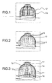
Figure 1 is a schematic perspective view which shows the structure supporting the dome of a system according to the invention; -
Figure 2 is a schematic perspective view which shows the panels supported by the structure according toFigure 1 ; -
Figure 3 is a view similar toFigure 2 and showing also a sun simulation lamp; -
Figures 4 and 5 are vertically sectioned schematic views along respective planes which are transverse and longitudinal relative to the longitudinal axis of the fuselage of an aircraft, the cockpit of which is arranged at the centre of the dome according toFigures 1-3 ; -
Figure 6 is a plan view of the configuration shown inFigures 4 and 5 ; -
Figures 7 and 8 are views similar toFigure 5 , but with the sun simulation lamp in two further positions; -
Figure 9 is a schematic plan view which shows distribution of the light-emitting panels and the reflective panels on the inner vault of the dome; -
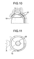
Figures 10 and 11 are, respectively, a vertically sectioned view and a plan view which show schematically a series of curtains for recreating total darkness conditions around the cockpit. - Referring initially to
Figures 1-3 , a system according to the invention comprises a mesh-likemetallic structure 12 with a hemispherical dome, the inner vault or covering of which consists of an ordered arrangement of light-emittingpanels 10 andreflective panels 11 which have the function of reproducing artificially a diffused light condition in the sky, as described more clearly below. In the simulation system according to the invention, the sky is not regarded as a continuous surface, but is reproduced discretely by a given number of polygonal panels. - By way of a non-limiting example, the dome has an internal diameter of 12 m so as to be able to house the front part of the fuselage of a small-size aircraft A or a medium-size transportation aircraft. The dome may be equally well formed as a hemisphere which extends underneath the horizon line through at least 24° or (as in the embodiment shown in the drawings) as a hemisphere mounted on top of a vertical
cylindrical drum 13 having the same radius as the dome and being lined internally with light-emitting panels 10 and/orreflective panels 11. The surface of the dome is interrupted by anopening 14 for allowing the entry of the front part of the fuselage of the aircraft being tested. A rail-type movement system (not shown) allows the aircraft to be towed inside the dome, positioning the cockpit in the centre thereof. The possibility of installing in the system a raisable platform (not shown) for positioning the cockpit, and therefore the pilot's head, in the centre of the dome, is also envisaged. - With the aircraft arranged as shown in
Figure 5 , theopening 14 is then sealed by curtains orscreens 15 which isolate the internal lit environment from the external environment. - The lighting conditions inside the dome must be able to be completely controlled artificially and not be affected by (chinks of) light entering from outside.
- The light-emitting
panels 10 are lit with the possibility of adjusting their intensity, or switched off, depending on the lighting conditions which are to be created and for which it is required to verify the "readability" of the on-board instrumentation and the simultaneous possibility of the pilot being able to see outside. - As shown schematically in
Figure 9 , the light-emitting panels 10 are preferably concentrated in the front and rear zone of the dome in an arrangement distributed in the manner of lunes. This configuration ensures that thepanels 10, when lit, give rise to one of the visibility conditions considered to be most critical for the pilot: dazzling effect due to a lot of light from the front; and mirror-like reflection on the instrument displays of the light from behind. This condition is, for example, useful for evaluating the use of certain types of display, the information on which is poorly visible when the surrounding light is particularly strong. As an alternative to the example shown, the light-emitting panels 10 may line the whole of the inside of the dome. - The light-emitting
panels 10 may contain equally well fluorescent tubes, or LED arrays, or light sources of another kind, the luminous intensity of which may be modulated with different voltage levels so as to emit more or less light with a view to recreating artificially, in a selective manner, lighting conditions representing some particularly critical conditions which the pilot may encounter whilst flying. The fluorescent tubes are covered by a diffusing screen which ensures the uniformity of the light emitted by each panel. The switching-on and modulation of each light-emitting panel or each subassembly of light sources forming a panel is controlled individually by software which allows suitable mapping of various sky illumination models. - The light-emitting or reflective panels which line the
cylindrical drum 13 at the base of the dome have the function of recreating another critical visibility situation, where the aircraft is situated above a blanket of clouds while the sky above is clear with radiant sunshine. This is a "saturation" light condition where the panels in the base drum simulate the layer of clouds which reflect the sunlight. - A powerful directable floodlight 16 (for example with a power of 12 kW) has the function of simulating the direct light from the sun. The
floodlight 16 is designed to have the same apparent size as the round ball of sun viewed from the cockpit which is situated in the centre of the dome and is able to concentrate the light onto the cockpit and provide a lighting strength of at least 150,000 lux in the centre of the dome. Thefloodlight 16 is mounted on an articulatedcurved arm 17, the base of which is able to travel along acurved rail 18 situated at the bottom of the dome. The azimuth and height of the articulatedarm 17 are adjustable so as to arrange the floodlight or "sun" 16 virtually in any position around or above the cockpit and in any case in the most critical positions as regards visibility. For example, inFigures 4 to 6 , the "sun" 16 is situated directly in front on the horizon; inFigure 7 it is inclined at 30° at the rear of the aircraft and inFigure 8 it is situated at its highest point. By varying the position of thefloodlight 16, which can be directed so as to project onto the cockpit a beam of light which simulates the direct sunlight and, if necessary, by adjusting the light-emittingpanels 10 depending on the conditions which are to be recreated, it is possible to verify the visibility of the on-board instruments virtually in any condition. - With the system according to the invention it is possible to create darkness conditions in order to simulate night time flights, for example so as to check the suitability of the cockpit for use with image intensifiers ("night vision goggles"). As shown schematically in
Figures 10 and 11 , a series of blackopaque curtains 19 supported onmetal rings 20 can be raised by means of winches so as to obscure completely the zone surrounding the aircraft cockpit. A suitable light source (not shown) simulates different night-time lighting conditions, for example a full moon, quarter moon, star light, etc. - In order to verify the effectiveness, in particular, of the so-called "Head-Up Display" (HUD), the system may envisage a pair of floodlights (not shown) which illuminate a reflective panel (not shown) situated in front of the pilot. This has the function of simulating a dazzling condition due to the diffused light of surrounding clouds, with particular attention to the field of vision of the pilot during reading of the symbols which appear on the display, for example on the HUD.
- The system according to the present invention is moreover equipped with:
- a cooling and conditioning plant which performs ventilation of each individual panel, ensuring not only cooling thereof during operational use, but also elimination of any inflammable vapours and conservation of the chromatic properties of the light;
- a subassembly designed to perform cooling of the solar floodlight;
- a subassembly for detecting/signalling inflammable vapours, smoke and fire and for extinguishing fires; and
- a TV intercommunication and monitoring system which allows communication between the personnel operating the system and the personnel in the aircraft cockpit who are recording the luminosity and visibility conditions created by the system. The illumination of the various light sources of the system and the movement of the associated support means is performed by means of software and/or commands which are emitted by an electronic control and processing unit 21 - typically a PLC (Programmable Logic Controller) or a PC (Personal Computer) - which supervises operation of the system overall and therefore also operation of all the driving/actuating members described here. The electronic control and processing unit 21 therefore performs:
- monitoring of the main systems and subsystems of the installation (lighting, electrical, fire detection and cooling systems);
- control of the lighting system (vault panels, sun simulator, moon/star simulator), electrical and alarm system;
- data processing (test reports, panel performance and warning diagrams).
- It is envisaged providing the possibility of controlling the various light sources of the system in order to perform both "static" and "dynamic" light tests, with a continuous or sudden variation of the light.
- As can be understood, the present invention provides the possibility of performing test activities, without having to take into account the weather conditions (which may instead hinder execution of in-flight tests). Moreover, with the system it is possible to reproduce, on the ground, lighting conditions which are required by the regulations for certification of the aircraft and which are difficult to achieve during flights.
- Experts in the aeronautical sector will note that the system according to the invention overcomes the limitations of other lighting facilities which at present exist throughout the world, namely:
- limited dimensions: the invention, instead, is able to cover a range of -24° to +90° in the vertical plane and 360° in the azimuthal plane;
- the limited lighting levels which can be achieved: with the invention, instead, it is possible to create at least 150,000 lux in the vault centre for the sun and at least 10,000 cd/m2 for the light-emitting panels.
- the poor uniformity and distribution of the light: in the system according to the invention, the standard deviation as regards uniformity is 10%;
- the unrealistic size of the "sun": in the system according to the invention, instead, the size of the
floodlight 16 is such as to reproduce the apparent size of the sun; - the impossibility of using real aircraft during the cockpit lighting tests.
- By simulating on the ground in a repeatable and reliable manner the lighting environment to which the equipment is operationally exposed during flying, the simulation system allows the on-ground design and testing of the visual interface, reducing the costs and the risks associated with in-flight testing activities.
- Owing to its modular design and the light-emitting panels, the system is able to house internally not only simulated cockpits of almost any size (therefore constituting a valid tool during design and testing of the visual interface of any new aircraft), but also the fuselage part containing the cockpit of aircraft of varying sizes, including those with medium-size bodies (such as the B737), therefore also providing a valid tool for testing and validating, on the ground, modifications made to already existing aircraft or aircraft in the advanced stage of design.
- Besides being used for the tests relating to the lighting system of aircraft, the system according to the present invention may be used for test activities in connection with the following:
- evaluation of the lighting system of helicopters;
- evaluation of the lighting system of vehicles (land vehicles, motorcars, lorries, etc.);
- evaluation of architectural designs, to be applied to models or to real structures/components;
- any evaluation of a man/machine interface which involves the surrounding lighting.
Claims (12)
- System for on-ground simulation of lighting conditions in the cockpit of an aircraft (A), comprising:a dome structure sized such as to house at least the cockpit of an aircraft;an ordered arrangement of light-emitting panels (10) forming at least a part of the inner vault of the dome, able to be lit or switched off selectively;a floodlight (16) mounted on movable support means (17) such that it can be selectively positioned around or above the cockpit and directed so as to project a beam of light onto the cockpit.
- A system according to Claim 1, further comprising an ordered arrangement of reflective panels (11) forming at least a part of the inner vault of the dome.
- A system according to Claim 2, further comprising a vertical cylindrical drum structure (13) on which said dome structure is mounted and having an inner surface lined with reflective panels (11).
- A system according to any one of the preceding claims, having an opening (14) at the base of the structure for allowing the entry of the front part of the aircraft fuselage.
- A system according to Claim 4, comprising opaque screen means (15) associated with the opening (14) for sealing off the space between the said opening and the aircraft which passes through it.
- A system according to any one of the preceding claims, wherein the light-emitting panels (10) are individually adjustable so as to emit light of variable intensity.
- A system according to Claim 1, wherein the floodlight (16) is designed so as to have the same apparent size as the round ball of sun viewed from a cockpit situated in the centre of the dome.
- A system according to Claim 1, wherein the floodlight (16) is mounted on an articulated arm (17), the height and azimuth of which can be adjusted.
- A system according to Claim 8, wherein the articulated arm (17) is slidable along a curved rail (18) situated at the bottom of the dome.
- A system according to Claim 1, wherein the articulated arm (17) comprises a curved part.
- A system according to Claim 1 or 2, wherein the light-emitting panels (10) are concentrated in two opposite zones relative to the top of the dome, so as to illuminate zones of the dome arranged at the front and rear of a cockpit situated approximately in the centre of the dome.
- System according to any one of the preceding claims, further comprising opaque screen means (19) mounted movably inside the dome so as to obscure the zone surrounding the cockpit.
Applications Claiming Priority (2)
| Application Number | Priority Date | Filing Date | Title |
|---|---|---|---|
| IT000923A ITTO20060923A1 (en) | 2006-12-27 | 2006-12-27 | SYSTEM FOR THE GROUND SIMULATION OF ENVIRONMENTAL LIGHTING CONDITIONS IN THE PILOT BOOTH OF AN AIRWAY IN AIRCRAFT. |
| PCT/IB2007/054978 WO2008081367A2 (en) | 2006-12-27 | 2007-12-10 | System for on-ground simulation of the ambient lighting conditions in the cockpit of an aircraft during flight |
Publications (2)
| Publication Number | Publication Date |
|---|---|
| EP2125520A2 EP2125520A2 (en) | 2009-12-02 |
| EP2125520B1 true EP2125520B1 (en) | 2010-05-19 |
Family
ID=39481212
Family Applications (1)
| Application Number | Title | Priority Date | Filing Date |
|---|---|---|---|
| EP07849384A Not-in-force EP2125520B1 (en) | 2006-12-27 | 2007-12-10 | System for on-ground simulation of the ambient lighting conditions in the cockpit of an aircraft during flight |
Country Status (7)
| Country | Link |
|---|---|
| US (1) | US8186860B2 (en) |
| EP (1) | EP2125520B1 (en) |
| AT (1) | ATE468267T1 (en) |
| DE (1) | DE602007006695D1 (en) |
| ES (1) | ES2346162T3 (en) |
| IT (1) | ITTO20060923A1 (en) |
| WO (1) | WO2008081367A2 (en) |
Families Citing this family (12)
| Publication number | Priority date | Publication date | Assignee | Title |
|---|---|---|---|---|
| ITTO20060923A1 (en) | 2006-12-27 | 2008-06-28 | Alenia Aeronautica Spa | SYSTEM FOR THE GROUND SIMULATION OF ENVIRONMENTAL LIGHTING CONDITIONS IN THE PILOT BOOTH OF AN AIRWAY IN AIRCRAFT. |
| US9916768B2 (en) * | 2016-01-15 | 2018-03-13 | The Boeing Company | Systems and methods for providing sunlight simulation in a vehicle simulator |
| US10091497B2 (en) * | 2016-02-04 | 2018-10-02 | The Boeing Company | Night vision imagining system acuity verification test fixture |
| FR3063488B1 (en) * | 2017-03-06 | 2019-08-23 | Nexeya France | DEVICE FOR LIGHTING THE INTERIOR OF AN AIRCRAFT |
| CN109896045B (en) * | 2017-12-11 | 2023-06-09 | 上海航空电器有限公司 | Device and method for testing optical environment of cockpit |
| CN110360483B (en) * | 2019-06-13 | 2022-01-28 | 上海复瞻智能科技有限公司 | Partitioning method for simulating natural light |
| CN111678066A (en) * | 2020-06-10 | 2020-09-18 | 深圳紫泓光学技术有限公司 | Lighting system for simulating sunlight irradiation skylight |
| CN113120261B (en) * | 2021-04-30 | 2023-01-10 | 北京吾天科技有限公司 | Auxiliary device for simulating control of instrument and equipment by astronaut on ground |
| CN114537708B (en) * | 2022-04-26 | 2022-07-29 | 中国飞机强度研究所 | Solar irradiation simulation test device for airplane test and simulation test method thereof |
| CN115223422A (en) * | 2022-08-12 | 2022-10-21 | 中国商用飞机有限责任公司 | Sky light environment simulation system |
| CN116013131B (en) * | 2023-02-02 | 2026-04-28 | 北京东方瑞丰航空技术有限公司 | A visual system and control method for a flight simulator based on direct projection |
| CN115985164A (en) * | 2023-02-07 | 2023-04-18 | 北京东方瑞丰航空技术有限公司 | A flight simulator vision system and control method based on diffuse reflection |
Family Cites Families (7)
| Publication number | Priority date | Publication date | Assignee | Title |
|---|---|---|---|---|
| US3321620A (en) * | 1963-08-05 | 1967-05-23 | Linear Inc | Solar simulator |
| US5158497A (en) * | 1991-02-07 | 1992-10-27 | The State Of Oregon Acting By And Through The Oregon State Board Of Higher Education On Behalf Of Oregon State University | Mating chamber for honey bees |
| DE10045028B8 (en) * | 2000-09-12 | 2006-08-24 | Mitronic P. Miller Gmbh | Lighting system for the simulation of sunlight and a method for illuminating a lighting object by simulation of the sunlight |
| DE202004006432U1 (en) * | 2004-04-23 | 2004-07-22 | Zweibrüder Optoelectronics GmbH | reflector lamp |
| US7178947B2 (en) * | 2004-06-04 | 2007-02-20 | Dale Marks | Lighting device with elliptical fresnel mirror |
| FR2898586B1 (en) * | 2006-03-15 | 2008-04-18 | Airbus France Sas | TOOL FOR DESIGNING AN AIRCRAFT AIRCRAFT COMPATIBLE WITH A NIGHT VISION SYSTEM |
| ITTO20060923A1 (en) | 2006-12-27 | 2008-06-28 | Alenia Aeronautica Spa | SYSTEM FOR THE GROUND SIMULATION OF ENVIRONMENTAL LIGHTING CONDITIONS IN THE PILOT BOOTH OF AN AIRWAY IN AIRCRAFT. |
-
2006
- 2006-12-27 IT IT000923A patent/ITTO20060923A1/en unknown
-
2007
- 2007-12-10 DE DE602007006695T patent/DE602007006695D1/en active Active
- 2007-12-10 ES ES07849384T patent/ES2346162T3/en active Active
- 2007-12-10 EP EP07849384A patent/EP2125520B1/en not_active Not-in-force
- 2007-12-10 WO PCT/IB2007/054978 patent/WO2008081367A2/en not_active Ceased
- 2007-12-10 US US12/519,875 patent/US8186860B2/en active Active
- 2007-12-10 AT AT07849384T patent/ATE468267T1/en not_active IP Right Cessation
Also Published As
| Publication number | Publication date |
|---|---|
| WO2008081367A2 (en) | 2008-07-10 |
| WO2008081367A3 (en) | 2008-08-28 |
| US8186860B2 (en) | 2012-05-29 |
| EP2125520A2 (en) | 2009-12-02 |
| ATE468267T1 (en) | 2010-06-15 |
| US20100033979A1 (en) | 2010-02-11 |
| ITTO20060923A1 (en) | 2008-06-28 |
| ES2346162T3 (en) | 2010-10-11 |
| DE602007006695D1 (en) | 2010-07-01 |
Similar Documents
| Publication | Publication Date | Title |
|---|---|---|
| US8186860B2 (en) | System for on-ground simulation of the ambient lighting conditions in the cockpit of an aircraft during flight | |
| US9916768B2 (en) | Systems and methods for providing sunlight simulation in a vehicle simulator | |
| EP3039336B1 (en) | Lighting system | |
| Allerton | The impact of flight simulation in aerospace | |
| US8337206B2 (en) | Tool for assisting in the design of an aircraft flight deck compatible with a night vision system | |
| CN104627384B (en) | Large aircraft flight deck lighting environmental simulation evaluation system and its assessment method | |
| US20170320593A1 (en) | Helipad and helipad illumination system | |
| CN102152859B (en) | Airplane cockpit luminous environment simulation assessment system and method | |
| EP3202308B1 (en) | Night vision imaging system acuity verification test fixture | |
| CN110360483B (en) | Partitioning method for simulating natural light | |
| US12529950B2 (en) | Simulator projection system | |
| BATSON et al. | Design, development and testing of an ambient lighting simulator forexternal illumination of a transport simulator cockpit | |
| Guo et al. | Equipment for Simulating the External Light Environment of Aircraft Cockpit | |
| Clark et al. | Spacecraft Lighting Systems Challenges & Potential for Innovation | |
| US3818612A (en) | Visual system for rotary-wing aircraft | |
| US20260002658A1 (en) | Dynamic light for a driving simulator | |
| JP2005157234A (en) | Exterior character display device | |
| Guo et al. | Design and Research of Advanced Test Equipment for Simulating the External Light Environment of Aircraft Cockpit | |
| Ellersick | Boeing Technical Journal A History of Boeing Commercial Transport Flight Deck Lighting and Display Optics Innovation | |
| Urmer et al. | The visual sub-system concept and spacecraft illumination | |
| Wheelwright | Apollo experience report: crew station integration. Volume 5: Lighting considerations | |
| CN111473278A (en) | Device for flat-plate type simulation of low-light-level light source in natural night sky and application method thereof | |
| WO2023220769A1 (en) | Synthetic training device cockpit panel | |
| Reynolds | The visual effects of exposure to electroluminescent instrument lighting | |
| Squair | Human engineering for Australia’s F/A-18 night vision capability |
Legal Events
| Date | Code | Title | Description |
|---|---|---|---|
| PUAI | Public reference made under article 153(3) epc to a published international application that has entered the european phase |
Free format text: ORIGINAL CODE: 0009012 |
|
| GRAP | Despatch of communication of intention to grant a patent |
Free format text: ORIGINAL CODE: EPIDOSNIGR1 |
|
| 17P | Request for examination filed |
Effective date: 20090709 |
|
| AK | Designated contracting states |
Kind code of ref document: A2 Designated state(s): AT BE BG CH CY CZ DE DK EE ES FI FR GB GR HU IE IS IT LI LT LU LV MC MT NL PL PT RO SE SI SK TR |
|
| DAX | Request for extension of the european patent (deleted) | ||
| GRAS | Grant fee paid |
Free format text: ORIGINAL CODE: EPIDOSNIGR3 |
|
| GRAA | (expected) grant |
Free format text: ORIGINAL CODE: 0009210 |
|
| AK | Designated contracting states |
Kind code of ref document: B1 Designated state(s): AT BE BG CH CY CZ DE DK EE ES FI FR GB GR HU IE IS IT LI LT LU LV MC MT NL PL PT RO SE SI SK TR |
|
| REG | Reference to a national code |
Ref country code: GB Ref legal event code: FG4D |
|
| REG | Reference to a national code |
Ref country code: CH Ref legal event code: EP |
|
| REG | Reference to a national code |
Ref country code: IE Ref legal event code: FG4D |
|
| REF | Corresponds to: |
Ref document number: 602007006695 Country of ref document: DE Date of ref document: 20100701 Kind code of ref document: P |
|
| REG | Reference to a national code |
Ref country code: SE Ref legal event code: TRGR |
|
| REG | Reference to a national code |
Ref country code: NL Ref legal event code: VDEP Effective date: 20100519 |
|
| REG | Reference to a national code |
Ref country code: ES Ref legal event code: FG2A Ref document number: 2346162 Country of ref document: ES Kind code of ref document: T3 |
|
| LTIE | Lt: invalidation of european patent or patent extension |
Effective date: 20100519 |
|
| PG25 | Lapsed in a contracting state [announced via postgrant information from national office to epo] |
Ref country code: LT Free format text: LAPSE BECAUSE OF FAILURE TO SUBMIT A TRANSLATION OF THE DESCRIPTION OR TO PAY THE FEE WITHIN THE PRESCRIBED TIME-LIMIT Effective date: 20100519 |
|
| PG25 | Lapsed in a contracting state [announced via postgrant information from national office to epo] |
Ref country code: AT Free format text: LAPSE BECAUSE OF FAILURE TO SUBMIT A TRANSLATION OF THE DESCRIPTION OR TO PAY THE FEE WITHIN THE PRESCRIBED TIME-LIMIT Effective date: 20100519 Ref country code: FI Free format text: LAPSE BECAUSE OF FAILURE TO SUBMIT A TRANSLATION OF THE DESCRIPTION OR TO PAY THE FEE WITHIN THE PRESCRIBED TIME-LIMIT Effective date: 20100519 Ref country code: IS Free format text: LAPSE BECAUSE OF FAILURE TO SUBMIT A TRANSLATION OF THE DESCRIPTION OR TO PAY THE FEE WITHIN THE PRESCRIBED TIME-LIMIT Effective date: 20100919 Ref country code: LV Free format text: LAPSE BECAUSE OF FAILURE TO SUBMIT A TRANSLATION OF THE DESCRIPTION OR TO PAY THE FEE WITHIN THE PRESCRIBED TIME-LIMIT Effective date: 20100519 Ref country code: SI Free format text: LAPSE BECAUSE OF FAILURE TO SUBMIT A TRANSLATION OF THE DESCRIPTION OR TO PAY THE FEE WITHIN THE PRESCRIBED TIME-LIMIT Effective date: 20100519 |
|
| PG25 | Lapsed in a contracting state [announced via postgrant information from national office to epo] |
Ref country code: CY Free format text: LAPSE BECAUSE OF FAILURE TO SUBMIT A TRANSLATION OF THE DESCRIPTION OR TO PAY THE FEE WITHIN THE PRESCRIBED TIME-LIMIT Effective date: 20100616 Ref country code: PL Free format text: LAPSE BECAUSE OF FAILURE TO SUBMIT A TRANSLATION OF THE DESCRIPTION OR TO PAY THE FEE WITHIN THE PRESCRIBED TIME-LIMIT Effective date: 20100519 |
|
| PG25 | Lapsed in a contracting state [announced via postgrant information from national office to epo] |
Ref country code: DK Free format text: LAPSE BECAUSE OF FAILURE TO SUBMIT A TRANSLATION OF THE DESCRIPTION OR TO PAY THE FEE WITHIN THE PRESCRIBED TIME-LIMIT Effective date: 20100519 Ref country code: EE Free format text: LAPSE BECAUSE OF FAILURE TO SUBMIT A TRANSLATION OF THE DESCRIPTION OR TO PAY THE FEE WITHIN THE PRESCRIBED TIME-LIMIT Effective date: 20100519 Ref country code: NL Free format text: LAPSE BECAUSE OF FAILURE TO SUBMIT A TRANSLATION OF THE DESCRIPTION OR TO PAY THE FEE WITHIN THE PRESCRIBED TIME-LIMIT Effective date: 20100519 Ref country code: PT Free format text: LAPSE BECAUSE OF FAILURE TO SUBMIT A TRANSLATION OF THE DESCRIPTION OR TO PAY THE FEE WITHIN THE PRESCRIBED TIME-LIMIT Effective date: 20100920 |
|
| PG25 | Lapsed in a contracting state [announced via postgrant information from national office to epo] |
Ref country code: CZ Free format text: LAPSE BECAUSE OF FAILURE TO SUBMIT A TRANSLATION OF THE DESCRIPTION OR TO PAY THE FEE WITHIN THE PRESCRIBED TIME-LIMIT Effective date: 20100519 Ref country code: SK Free format text: LAPSE BECAUSE OF FAILURE TO SUBMIT A TRANSLATION OF THE DESCRIPTION OR TO PAY THE FEE WITHIN THE PRESCRIBED TIME-LIMIT Effective date: 20100519 Ref country code: BE Free format text: LAPSE BECAUSE OF FAILURE TO SUBMIT A TRANSLATION OF THE DESCRIPTION OR TO PAY THE FEE WITHIN THE PRESCRIBED TIME-LIMIT Effective date: 20100519 Ref country code: RO Free format text: LAPSE BECAUSE OF FAILURE TO SUBMIT A TRANSLATION OF THE DESCRIPTION OR TO PAY THE FEE WITHIN THE PRESCRIBED TIME-LIMIT Effective date: 20100519 |
|
| PLBE | No opposition filed within time limit |
Free format text: ORIGINAL CODE: 0009261 |
|
| STAA | Information on the status of an ep patent application or granted ep patent |
Free format text: STATUS: NO OPPOSITION FILED WITHIN TIME LIMIT |
|
| PG25 | Lapsed in a contracting state [announced via postgrant information from national office to epo] |
Ref country code: IT Free format text: LAPSE BECAUSE OF FAILURE TO SUBMIT A TRANSLATION OF THE DESCRIPTION OR TO PAY THE FEE WITHIN THE PRESCRIBED TIME-LIMIT Effective date: 20100519 |
|
| 26N | No opposition filed |
Effective date: 20110222 |
|
| PG25 | Lapsed in a contracting state [announced via postgrant information from national office to epo] |
Ref country code: GR Free format text: LAPSE BECAUSE OF FAILURE TO SUBMIT A TRANSLATION OF THE DESCRIPTION OR TO PAY THE FEE WITHIN THE PRESCRIBED TIME-LIMIT Effective date: 20100820 |
|
| REG | Reference to a national code |
Ref country code: DE Ref legal event code: R097 Ref document number: 602007006695 Country of ref document: DE Effective date: 20110221 |
|
| PG25 | Lapsed in a contracting state [announced via postgrant information from national office to epo] |
Ref country code: MC Free format text: LAPSE BECAUSE OF NON-PAYMENT OF DUE FEES Effective date: 20101231 |
|
| PG25 | Lapsed in a contracting state [announced via postgrant information from national office to epo] |
Ref country code: IE Free format text: LAPSE BECAUSE OF NON-PAYMENT OF DUE FEES Effective date: 20101210 |
|
| PG25 | Lapsed in a contracting state [announced via postgrant information from national office to epo] |
Ref country code: MT Free format text: LAPSE BECAUSE OF FAILURE TO SUBMIT A TRANSLATION OF THE DESCRIPTION OR TO PAY THE FEE WITHIN THE PRESCRIBED TIME-LIMIT Effective date: 20100519 |
|
| REG | Reference to a national code |
Ref country code: CH Ref legal event code: PL |
|
| PG25 | Lapsed in a contracting state [announced via postgrant information from national office to epo] |
Ref country code: LU Free format text: LAPSE BECAUSE OF NON-PAYMENT OF DUE FEES Effective date: 20101210 Ref country code: BG Free format text: LAPSE BECAUSE OF FAILURE TO SUBMIT A TRANSLATION OF THE DESCRIPTION OR TO PAY THE FEE WITHIN THE PRESCRIBED TIME-LIMIT Effective date: 20100519 Ref country code: HU Free format text: LAPSE BECAUSE OF FAILURE TO SUBMIT A TRANSLATION OF THE DESCRIPTION OR TO PAY THE FEE WITHIN THE PRESCRIBED TIME-LIMIT Effective date: 20101120 |
|
| PG25 | Lapsed in a contracting state [announced via postgrant information from national office to epo] |
Ref country code: CH Free format text: LAPSE BECAUSE OF NON-PAYMENT OF DUE FEES Effective date: 20111231 Ref country code: LI Free format text: LAPSE BECAUSE OF NON-PAYMENT OF DUE FEES Effective date: 20111231 Ref country code: TR Free format text: LAPSE BECAUSE OF FAILURE TO SUBMIT A TRANSLATION OF THE DESCRIPTION OR TO PAY THE FEE WITHIN THE PRESCRIBED TIME-LIMIT Effective date: 20100519 |
|
| PG25 | Lapsed in a contracting state [announced via postgrant information from national office to epo] |
Ref country code: BG Free format text: LAPSE BECAUSE OF FAILURE TO SUBMIT A TRANSLATION OF THE DESCRIPTION OR TO PAY THE FEE WITHIN THE PRESCRIBED TIME-LIMIT Effective date: 20100819 |
|
| REG | Reference to a national code |
Ref country code: FR Ref legal event code: PLFP Year of fee payment: 9 |
|
| REG | Reference to a national code |
Ref country code: FR Ref legal event code: PLFP Year of fee payment: 10 |
|
| PGFP | Annual fee paid to national office [announced via postgrant information from national office to epo] |
Ref country code: SE Payment date: 20161221 Year of fee payment: 10 |
|
| REG | Reference to a national code |
Ref country code: FR Ref legal event code: PLFP Year of fee payment: 11 |
|
| PG25 | Lapsed in a contracting state [announced via postgrant information from national office to epo] |
Ref country code: SE Free format text: LAPSE BECAUSE OF NON-PAYMENT OF DUE FEES Effective date: 20171211 |
|
| PGFP | Annual fee paid to national office [announced via postgrant information from national office to epo] |
Ref country code: GB Payment date: 20231220 Year of fee payment: 17 |
|
| PGFP | Annual fee paid to national office [announced via postgrant information from national office to epo] |
Ref country code: FR Payment date: 20231220 Year of fee payment: 17 Ref country code: DE Payment date: 20231214 Year of fee payment: 17 |
|
| PGFP | Annual fee paid to national office [announced via postgrant information from national office to epo] |
Ref country code: ES Payment date: 20240102 Year of fee payment: 17 |
|
| REG | Reference to a national code |
Ref country code: DE Ref legal event code: R119 Ref document number: 602007006695 Country of ref document: DE |
|
| GBPC | Gb: european patent ceased through non-payment of renewal fee |
Effective date: 20241210 |
|
| PG25 | Lapsed in a contracting state [announced via postgrant information from national office to epo] |
Ref country code: DE Free format text: LAPSE BECAUSE OF NON-PAYMENT OF DUE FEES Effective date: 20250701 |
|
| PG25 | Lapsed in a contracting state [announced via postgrant information from national office to epo] |
Ref country code: GB Free format text: LAPSE BECAUSE OF NON-PAYMENT OF DUE FEES Effective date: 20241210 |
|
| PG25 | Lapsed in a contracting state [announced via postgrant information from national office to epo] |
Ref country code: FR Free format text: LAPSE BECAUSE OF NON-PAYMENT OF DUE FEES Effective date: 20241231 |
|
| REG | Reference to a national code |
Ref country code: ES Ref legal event code: FD2A Effective date: 20260128 |
|
| PG25 | Lapsed in a contracting state [announced via postgrant information from national office to epo] |
Ref country code: ES Free format text: LAPSE BECAUSE OF NON-PAYMENT OF DUE FEES Effective date: 20241211 |