EP2124367A1 - Multi-carrier communication apparatus - Google Patents
Multi-carrier communication apparatus Download PDFInfo
- Publication number
- EP2124367A1 EP2124367A1 EP07736877A EP07736877A EP2124367A1 EP 2124367 A1 EP2124367 A1 EP 2124367A1 EP 07736877 A EP07736877 A EP 07736877A EP 07736877 A EP07736877 A EP 07736877A EP 2124367 A1 EP2124367 A1 EP 2124367A1
- Authority
- EP
- European Patent Office
- Prior art keywords
- signal
- carrier
- frequency
- offset
- sub
- Prior art date
- Legal status (The legal status is an assumption and is not a legal conclusion. Google has not performed a legal analysis and makes no representation as to the accuracy of the status listed.)
- Granted
Links
Images





Classifications
-
- H—ELECTRICITY
- H04—ELECTRIC COMMUNICATION TECHNIQUE
- H04L—TRANSMISSION OF DIGITAL INFORMATION, e.g. TELEGRAPHIC COMMUNICATION
- H04L27/00—Modulated-carrier systems
- H04L27/26—Systems using multi-frequency codes
- H04L27/2601—Multicarrier modulation systems
- H04L27/2647—Arrangements specific to the receiver only
- H04L27/2655—Synchronisation arrangements
- H04L27/2657—Carrier synchronisation
- H04L27/2659—Coarse or integer frequency offset determination and synchronisation
-
- H—ELECTRICITY
- H04—ELECTRIC COMMUNICATION TECHNIQUE
- H04L—TRANSMISSION OF DIGITAL INFORMATION, e.g. TELEGRAPHIC COMMUNICATION
- H04L27/00—Modulated-carrier systems
- H04L27/26—Systems using multi-frequency codes
- H04L27/2601—Multicarrier modulation systems
- H04L27/2602—Signal structure
- H04L27/261—Details of reference signals
-
- H—ELECTRICITY
- H04—ELECTRIC COMMUNICATION TECHNIQUE
- H04L—TRANSMISSION OF DIGITAL INFORMATION, e.g. TELEGRAPHIC COMMUNICATION
- H04L27/00—Modulated-carrier systems
- H04L27/26—Systems using multi-frequency codes
- H04L27/2601—Multicarrier modulation systems
- H04L27/2647—Arrangements specific to the receiver only
Definitions
- the present invention relates to a multi-carrier communication apparatus that improves communication performance degradation caused by a frequency characteristic specific to a communication device, which cannot be easily avoided in design, in a multi-carrier communication system using a broad communication band.
- a broad and stable frequency characteristic including a DC component is demanded for a transmitter/receiver.
- the demand for a broad effective band and a narrow sub-carrier interval has been increasing in recent systems in order to implement a high data throughput.
- a filter, an RF element, etc. which are included in a signal system, must be implemented at a stable frequency characteristic.
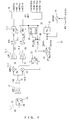
- Fig. 1 illustrates a receiver for a multi-carrier communication according to conventional technology.
- a carrier wave band reception signal that is received by an antenna 10 passes through a transmission/reception switch 11, a carrier wave bandpass filter 12, and a low noise amplifier 13.
- the frequency of the reception signal is converted by being multiplied in quadrature demodulators 14-1 and 14-2 by local carrier waves that are generated by adjusting the frequency of the output of a local oscillator 19 with a synthesizer 21 and are implemented as a 0° phase wave and a 90° phase wave with a phase shifter 22.
- the output of the local oscillator 19 is generated as a clock signal that is frequency-adjusted by a PLL (Phase Locked Loop) 20, and given to AD converters 17-1 and 17-2.
- the clock signal is used as a sampling signal in the AD converters 17-1 and 17-2.
- As the frequency of the clock signal a frequency double the band of a baseband signal is used.
- the signals pass through lowpass filters 15-1 and 15-2, and baseband signals are extracted. Their relations are expressed with the following equations. Alphabets enclosed with parentheses respectively indicate a signal passing through a corresponding portion.
- I-Branch local carrier wave B cos 2 ⁇ ⁇ f c ⁇ t
- Fig. 2 illustrates the spectrum of the multi-carrier communication reception signal received by the antenna 10.
- the sub-carriers are allocated at the frequency interval of fo [Hz], centering on the frequency of the carrier wave fc[Hz]. If N sub-carriers are used, the frequency band of the entire multi-carrier signal is Nfo[Hz].
- d(0) to d(N-1) of Fig. 2 correspond to those of Fig. 1 , and represent the symbols of the respective sub-carriers.
- d(0) and d(N-1) are unused sub-carriers called guard tones, and provided to prevent adjacent channels from being impeded.
- the number of sub-carriers of the guard tones on both sides is two.
- guard tones the number of which is approximately two-tenth of the total number of sub-carriers are used in an actual system. For example, if there are 100 sub-carriers, the total of 20 sub-carriers are defined as being unused on both sides of the signal band.
- d(2), d(N/2-1), d(N-3), etc. are known reference signals that are called pilot symbols and intended to detect synchronization.
- pilot symbols a sub-carrier the frequency of which is the same as the carrier wave frequency fc[Hz] is not used in normal cases. The reason is as follows: when being converted into a baseband signal, the carrier wave frequency fc becomes a DC component, on which 1/f noise is superimposed, an SNR therefore becomes small, and a signal error tends to occur despite the existence of a pilot symbol.
- Fig. 3 illustrates the spectrum of the reception signal when a frequency characteristic exists in the receiver.
- the example of Fig. 3 illustrates an influence exerted by 1/f noise existing in the vicinity of DC after the reception signal is frequency-converted into a baseband signal.
- the 1/F noise occurs in the quadrature demodulators 14-1, 14-2, etc. illustrated in Fig. 1 .
- a frequency characteristic, or the like which degrades the signal power, can possibly exist in the vicinity of a particular frequency.
- the symbols of d(N/2-1) and d(N/2+1) are degraded by the influence of the 1/f noise.
- a frequency interleaver For data sub-carriers and the frequency selective fading of a transmission channel, there are effective measures such as a frequency interleaver, etc.
- the frequency interleaver With the frequency interleaver, not sub-carriers of a fixed frequency but sub-carriers of different frequencies are used when the data symbols of one sequence are respectively transmitted.
- a synchronization detection method using a continuous pilot sub-carrier to which a particular frequency is allocated to transmit a pilot symbol there are no effective measures although a high SNR is demanded for the pilot symbol.
- a scattered pilot sub-carrier to which a temporally different frequency is allocated to transmit a pilot symbol, causes a similar problem if degradation is caused by a frequency characteristic in a range where the frequency of the pilot symbol changes.
- An object of the present invention is to provide a multi-carrier communication apparatus that can receive a pilot signal with less errors.
- a multi-carrier communication apparatus is a multi-carrier communication apparatus transmitting/receiving a signal composed of a plurality of sub-carriers, and comprises: a local carrier wave generating unit for generating a local carrier wave for demodulation; an offset adding unit for adding to the local carrier wave a frequency offset of a constant multiple of a frequency interval of a sub-carrier; and an offset varying unit for cyclically varying the constant of the offset.
- the signal is demodulated by using the local carrier wave to which the frequency offset is added.
- an SNR of a particular frequency component of an obtained baseband signal can be prevented from being constantly degraded by a frequency characteristic by adding an offset to a local carrier wave at the time of demodulation and by varying the offset, even if the SNR of the particular frequency component is degraded by the frequency characteristic of an element within a receiving device.
- the band of a baseband signal after being frequency-converted is shifted by cyclically varying the frequency of a local carrier wave used for down conversion performed in a mixer, etc. with an integer multiple of the frequency interval of a multi-carrier for each OFDM symbol, if an SNR is degraded by a particular frequency including DC (frequency 0) due to a circuit characteristic.
- the frequency of a signal which degrades the SNR, is converted to another frequency that does not degrade the SNR.
- the influence exerted by the degradation can be prevented from concentrating on a particular sub-carrier.
- both ends of an allocated frequency band are not used as guard tones.
- an unused band of 995 KHz of 91 sub-carriers exists at both ends of the band.
- the drift is cancelled by correcting a sub-carrier index, and the signal is received as if it were received at a fixed local frequency.
- Fig. 4 is a first configuration example of a multi-carrier receiver according to the embodiment of the present invention.
- This configuration is implemented by adding a divider 26, a multiplier 27 and a counter 25 to the conventional receiver illustrated in Fig. 1 .
- the signal is multiplied by an integer multiple a (namely, an offset) of a sub-carrier frequency (the local carrier wave that is the output of the synthesizer 21) (the signal after being multiplied by the offset is a signal of (J)).
- a is an offset control signal that cyclically vaires for each OFDM symbol, and can be obtained as the output of the counter 25.
- the counter 25 executes, for example, a process for cyclically counting up the value of a from 0 to 91.
- the output frequency Nfo (a signal of (H) in this figure) of a PLL 20 (cos (2 ⁇ Nf o t)) is used for the AD converters 17-1 and 17-2. Namely, this is a doubled frequency of the central frequency of the signal band to the frequency at the end of the signal band, and is the same frequency (Nf o ) as the band of the entire signal band.
- the frequency becomes an offset that shifts sub-carriers by the value of a (af o ).
- multiplying the output frequency of the PLL 20 by a/N generates a frequency offset (af o ) that shifts sub-carriers by the value of a.
- Figs. 5A and 5B illustrate a change in the spectrum of the reception signal, which is made by executing the above described process in the embodiment according to the present invention.
- the horizontal and the vertical axes represent a frequency and an SNR, respectively.
- one guard tone is respectively provided for one sub-carrier at both sides of the signal band (portions of d(0) and d(N-1)).
- the band is not shifted in Fig. 5A , 1 /f noise is superimposed on the DC portion. Therefore, the SNR decreases (the portion where the device frequency characteristic drops), and one SNR of the pilot signal at d (N/2-1) decreases.
- the amount of shift of the local carrier wave is sequentially varied, and the state where the local carrier wave is shifted, and the state where the local carrier wave is not shifted are cyclically repeated.
- I-Branch local carrier wave B cos 2 ⁇ ⁇ ⁇ f c + a ⁇ f 0 ⁇ t
- the pilot sub-carrier ⁇ d(N/2-1) ⁇ influenced by SNR degradation before being processed is not influenced any longer, and the data sub-carrier ⁇ d(N/2+1) ⁇ is influenced by the degradation in turn.
- the influence of the SNR degradation is scattered with the effects of frequency interleaving and an error correction according to conventional technology.
- Fig. 6 is a second configuration example of the multi-carrier receiver according to the embodiment of the present invention.
- the same components as those of Fig. 4 are denoted with the same reference numerals, and their descriptions are omitted.
- the output of the synthesizer 21 is multiplied by the output of the divider 26 in order to obtain an offset local carrier wave.
- the configuration illustrated in Fig. 6 is implemented by removing the divider 26 and the multiplier 27 from the configuration of Fig. 4 , and by adding the input of the offset control signal a to the synthesizer 21 instead.
- the value that the counter 25 gives to the synthesizer 21 is the same as the above described value.
- the synthesizer 21 multiplies a by the bandwidth (interval) of a sub-carrier preset within the synthesizer 21, and multiplies the local carrier wave by the offset.
- the offset local carrier wave represented below can be obtained as the output of the synthesizer 21.
- I-Branch local carrier wave B cos 2 ⁇ ⁇ ⁇ f c + a ⁇ f 0 ⁇ t
- the SNR can be improved as follows as a communication system without using a special process such as SiGe, etc. while using an element having a frequency characteristic that consumes less power and has an un satisfactory frequency characteristic.
- CNR n CNR A ⁇ 1 1 + 1 / SNR f ⁇ N subchan N subchan - N pilot + N pilot ⁇ SNR
- CNR A CNR in total band
- SNR f degradation ratio of frequency characteristic to pilot sub-carrier
- N subchan repetitive number of sub-carriers into which pilot symbol is inserted
- N pilot number of pilot sub-carriers per N subchan
- CNR n CNR A ⁇ 1 1 + 1 / SNR f / b ⁇ N subchan N subchan - N pilot + N pilot ⁇ SNR f / b
- SNR f is one-bth.
- a frequency offset may be directly added to a carrier wave of a transmission signal on the side of a transmitter, and the signal may be demodulated on the side of the receiver.
- a baseband signal after being demodulated is obtained with a frequency offset added. Therefore, the baseband signal is processed by being given an offset that cancels the offset on the transmission side to an extracted frequency component after being processed by the FFT unit.
- This method for canceling the offset may be the same as the method described with reference to Fig. 5 .
Landscapes
- Engineering & Computer Science (AREA)
- Computer Networks & Wireless Communication (AREA)
- Signal Processing (AREA)
- Digital Transmission Methods That Use Modulated Carrier Waves (AREA)
- Noise Elimination (AREA)
- Circuits Of Receivers In General (AREA)
Abstract
Description
- The present invention relates to a multi-carrier communication apparatus that improves communication performance degradation caused by a frequency characteristic specific to a communication device, which cannot be easily avoided in design, in a multi-carrier communication system using a broad communication band.
- In a multi-carrier communication using a plurality of carrier waves, a broad and stable frequency characteristic including a DC component is demanded for a transmitter/receiver. Additionally, the demand for a broad effective band and a narrow sub-carrier interval has been increasing in recent systems in order to implement a high data throughput. To meet such demands, a filter, an RF element, etc., which are included in a signal system, must be implemented at a stable frequency characteristic.
- If measures for suppressing frequency distortion in a filter, etc. are taken, power consumption generally increases. Moreover, an element must be manufactured with a semiconductor process using SiGe, etc., of a high unit price in order to suppress 1/f noise in the vicinity of DC, leading to an increase in the cost of the system.
-
Fig. 1 illustrates a receiver for a multi-carrier communication according to conventional technology.
A carrier wave band reception signal that is received by anantenna 10 passes through a transmission/reception switch 11, a carrierwave bandpass filter 12, and alow noise amplifier 13. Then, the frequency of the reception signal is converted by being multiplied in quadrature demodulators 14-1 and 14-2 by local carrier waves that are generated by adjusting the frequency of the output of alocal oscillator 19 with asynthesizer 21 and are implemented as a 0° phase wave and a 90° phase wave with aphase shifter 22. Moreover, the output of thelocal oscillator 19 is generated as a clock signal that is frequency-adjusted by a PLL (Phase Locked Loop) 20, and given to AD converters 17-1 and 17-2. The clock signal is used as a sampling signal in the AD converters 17-1 and 17-2. As the frequency of the clock signal, a frequency double the band of a baseband signal is used. Thereafter, the signals pass through lowpass filters 15-1 and 15-2, and baseband signals are extracted. Their relations are expressed with the following equations. Alphabets enclosed with parentheses respectively indicate a signal passing through a corresponding portion. - carrier wave band reception signal received by the antenna 10 (signal in a portion of (A))
-

where: - an=Ancosθn: InPhase component
- bn=Ansinθn: QuadraturePhase component
- N: Number of:MultiCariier
- local carrier waves generated by the
synthesizer 21 - [mathematical expression 2]
I-Branch local carrier wave
Q-Branch local carrier wave
- reception signals the frequency of which is converted by the quadrature demodulators 14-1 and 14-2
- [mathematical expression 3]
(D) I-Branch reception signal
(E)Q-Branch reception signal
- baseband signals after passing through the lowpass filters 15-1 and 15-2
- [mathematical expression 4]
(F)I-Branch baseband reception signal
where: - an = An cosθ n
- bn = An sinθ n
- an = An cosθ n
- bn = An sinθ n
-
Fig. 2 illustrates the spectrum of the multi-carrier communication reception signal received by theantenna 10.
The sub-carriers are allocated at the frequency interval of fo [Hz], centering on the frequency of the carrier wave fc[Hz]. If N sub-carriers are used, the frequency band of the entire multi-carrier signal is Nfo[Hz]. d(0) to d(N-1) ofFig. 2 correspond to those ofFig. 1 , and represent the symbols of the respective sub-carriers. d(0) and d(N-1) are unused sub-carriers called guard tones, and provided to prevent adjacent channels from being impeded. Here, the number of sub-carriers of the guard tones on both sides is two. However, guard tones the number of which is approximately two-tenth of the total number of sub-carriers are used in an actual system. For example, if there are 100 sub-carriers, the total of 20 sub-carriers are defined as being unused on both sides of the signal band. - In
Fig. 2 , d(2), d(N/2-1), d(N-3), etc. are known reference signals that are called pilot symbols and intended to detect synchronization. For the pilot symbols, a sub-carrier the frequency of which is the same as the carrier wave frequency fc[Hz] is not used in normal cases. The reason is as follows: when being converted into a baseband signal, the carrier wave frequency fc becomes a DC component, on which 1/f noise is superimposed, an SNR therefore becomes small, and a signal error tends to occur despite the existence of a pilot symbol. -
Fig. 3 illustrates the spectrum of the reception signal when a frequency characteristic exists in the receiver.
The example ofFig. 3 illustrates an influence exerted by 1/f noise existing in the vicinity of DC after the reception signal is frequency-converted into a baseband signal. The 1/F noise occurs in the quadrature demodulators 14-1, 14-2, etc. illustrated inFig. 1 . Additionally, a frequency characteristic, or the like, which degrades the signal power, can possibly exist in the vicinity of a particular frequency. In the case illustrated inFig. 3 , the symbols of d(N/2-1) and d(N/2+1) are degraded by the influence of the 1/f noise. - For data sub-carriers and the frequency selective fading of a transmission channel, there are effective measures such as a frequency interleaver, etc. With the frequency interleaver, not sub-carriers of a fixed frequency but sub-carriers of different frequencies are used when the data symbols of one sequence are respectively transmitted. However, for a synchronization detection method using a continuous pilot sub-carrier to which a particular frequency is allocated to transmit a pilot symbol, there are no effective measures although a high SNR is demanded for the pilot symbol. Also a scattered pilot sub-carrier, to which a temporally different frequency is allocated to transmit a pilot symbol, causes a similar problem if degradation is caused by a frequency characteristic in a range where the frequency of the pilot symbol changes.
- An object of the present invention is to provide a multi-carrier communication apparatus that can receive a pilot signal with less errors.
A multi-carrier communication apparatus according to the present invention is a multi-carrier communication apparatus transmitting/receiving a signal composed of a plurality of sub-carriers, and comprises: a local carrier wave generating unit for generating a local carrier wave for demodulation; an offset adding unit for adding to the local carrier wave a frequency offset of a constant multiple of a frequency interval of a sub-carrier; and an offset varying unit for cyclically varying the constant of the offset. In this apparatus, the signal is demodulated by using the local carrier wave to which the frequency offset is added. - According to the present invention, an SNR of a particular frequency component of an obtained baseband signal can be prevented from being constantly degraded by a frequency characteristic by adding an offset to a local carrier wave at the time of demodulation and by varying the offset, even if the SNR of the particular frequency component is degraded by the frequency characteristic of an element within a receiving device.
-
-
Fig. 1 illustrates a receiver for a multi-carrier communication in conventional technology; -
Fig. 2 illustrates the spectrum of a multi-carrier communication reception signal received by an antenna; -
Fig. 3 illustrates the spectrum of a reception signal when a frequency characteristic exists in a communication device; -
Fig. 4 is a first configuration example of a multi-carrier receiver according to an embodiment of the present invention; -
Fig. 5 illustrates a change in the spectrum of a reception signal, which is made by executing a process according to the embodiment of the present invention; and -
Fig. 6 is a second configuration example of the multi-carrier receiver according to the embodiment of the present invention. - In an embodiment according to the present invention, the band of a baseband signal after being frequency-converted is shifted by cyclically varying the frequency of a local carrier wave used for down conversion performed in a mixer, etc. with an integer multiple of the frequency interval of a multi-carrier for each OFDM symbol, if an SNR is degraded by a particular frequency including DC (frequency 0) due to a circuit characteristic. By shifting the band, the frequency of a signal, which degrades the SNR, is converted to another frequency that does not degrade the SNR. As a result, the influence exerted by the degradation can be prevented from concentrating on a particular sub-carrier.
- In a normal multi-carrier communication system, both ends of an allocated frequency band are not used as guard tones. For example, in the specifications of a WiMAX system, an effective band is 11.2 MHz× (841/1024)=9.19 MHz in the band of 11.2 MHz. In this case, an unused band of 995 KHz of 91 sub-carriers exists at both ends of the band.
- Accordingly, it is not difficult in the system to add an offset of the maximum of the guard tone band to the frequency of a local carrier wave. However, adding the offset drifts the allocation of sub-carriers in the baseband. This drift is an integer multiple of the frequency interval of the multi-carrier. Therefore, in the embodiment according to the present invention, the drift is cancelled by correcting a sub-carrier index, and the signal is received as if it were received at a fixed local frequency.
-
Fig. 4 is a first configuration example of a multi-carrier receiver according to the embodiment of the present invention.
InFig. 4 , the same components as those ofFig. 1 are denoted with the same reference numerals, and their descriptions are omitted. This configuration is implemented by adding adivider 26, amultiplier 27 and acounter 25 to the conventional receiver illustrated inFig. 1 . In this configuration, the signal is multiplied by an integer multiple a (namely, an offset) of a sub-carrier frequency (the local carrier wave that is the output of the synthesizer 21) (the signal after being multiplied by the offset is a signal of (J)). Here, a is an offset control signal that cyclically vaires for each OFDM symbol, and can be obtained as the output of thecounter 25. For example, if an unused portion of 91 sub-carriers exists, thecounter 25 executes, for example, a process for cyclically counting up the value of a from 0 to 91. Here, the output frequency Nfo (a signal of (H) in this figure) of a PLL 20 (cos (2πNfot)) is used for the AD converters 17-1 and 17-2. Namely, this is a doubled frequency of the central frequency of the signal band to the frequency at the end of the signal band, and is the same frequency (Nfo) as the band of the entire signal band. In the meantime, this becomes a frequency (fo) equivalent to the band width of one sub-carrier if it is divided by the number of sub-carriers N. Additionally, the frequency becomes an offset that shifts sub-carriers by the value of a (afo). Accordingly, multiplying the output frequency of thePLL 20 by a/N generates a frequency offset (afo) that shifts sub-carriers by the value of a. As a result, I=cos (2πafot) can be obtained, and the signal of (J) represented by a mathematical expression 7 can be obtained by being multiplied by cos (2πfct) of thesynthesizer 21. -
Figs. 5A and 5B illustrate a change in the spectrum of the reception signal, which is made by executing the above described process in the embodiment according to the present invention. In these figures, the horizontal and the vertical axes represent a frequency and an SNR, respectively. InFigs. 5A and 5B , one guard tone is respectively provided for one sub-carrier at both sides of the signal band (portions of d(0) and d(N-1)). Moreover, since the band is not shifted inFig. 5A ,1 /f noise is superimposed on the DC portion. Therefore, the SNR decreases (the portion where the device frequency characteristic drops), and one SNR of the pilot signal at d (N/2-1) decreases. In the embodiment according to the present invention, the baseband is shifted by shifting the frequency of a local carrier wave by afo (a=1 here) as illustrated inFig. 5B . Therefore, the entire signal band moves by fo, and the SNR of the pilot signal at d(N/2-1) is not degraded any more. In the meantime, the portion of the signal degradation becomes closer to the sub-carrier signal at d(N/2+1) by the shift of the signal band. Therefore, the SNR of the signal at d(N/2+1) decreases, and is degraded. In the case ofFig. 5B , the pilot signal is prevented from being degraded if it is left unchanged. Actually, however, a pilot signal of a smaller SNR can newly occur due to the existence of the frequency characteristic in another portion in the state where the local carrier wave is shifted. Accordingly, in the embodiment according to the present invention, the amount of shift of the local carrier wave is sequentially varied, and the state where the local carrier wave is shifted, and the state where the local carrier wave is not shifted are cyclically repeated. In the case ofFig. 5B , a=1. Therefore, cyclically repeating the amount of shift means that the case where the amount of shift is 0, and the case where the amount of shift is fo are alternately repeated. Accordingly, the state where the local carrier wave is not shifted as illustrated inFig. 5A and the pilot signal at d(N/2-1) is degraded, and the state where the local carrier wave is shifted by fo as illustrated inFig. 5B are repeated. Relations of the signals are represented with the following equations.
Alphabets enclosed with parentheses respectively represent a signal passing through a corresponding portion in a similar manner as inFig. 1 . - the output of the
PLL 20 - [mathematical expression 5]

where: - N: number of multi-carriers
- f0: frequency interval of multi-carrier
- the output of the
divider 26 - [mathematical expression 6]

where : - a = {0,1,2,... (Max absolute value = number of Guard Tone)}: SubCarrier offset
- the output of the
multiplier 27 - [mathematical expression 7]

- offset local carrier wave
- [mathematical expression 8]
I-Branch local carrier wave
Q-Branch local carrier wave
- reception signals the frequency of which is converted by the quadrature demodulators 14-1 and 14-2
- [mathematical expression 9]
(D)I-Branch reception signal
(E)Q-Branch reception signal
- baseband signals after passing through the lowpass filters 15-1 and 15-2
- [mathematical expression 10]
(F)I-Branch baseband reception signal
where: - an = An cosθ n
- bn = An sinθ n
- an = An cosθ n
- bn = An sinθ n
In the example ofFig. 5 , the maximum value of the sub-carrier offset a is the number ofguard tones 1 at one side. As a result, a cyclically takes the value of 0 to 1 to 0 to 1... every OFDM symbol. The basband signals after passing through the lowpass filters 15-1 and 15-2 in the case of a=1 inFig. 5 are represented with the following equations. - baseband signals after passing through the lowpass filters 15-1 and 15-2
- [mathematical expression 11]
(F)I-Branch baseband reception signal
where: - an = An cosθ n
- bn = An sinθ n
- an = An cosθ n
- bn = An sinθ n
- In the case of a=1 illustrated in
Fig. 5 , the pilot sub-carrier {d(N/2-1)} influenced by SNR degradation before being processed is not influenced any longer, and the data sub-carrier {d(N/2+1)} is influenced by the degradation in turn. However, the influence of the SNR degradation is scattered with the effects of frequency interleaving and an error correction according to conventional technology. -
Fig. 6 is a second configuration example of the multi-carrier receiver according to the embodiment of the present invention.
InFig. 6 , the same components as those ofFig. 4 are denoted with the same reference numerals, and their descriptions are omitted.
In the above described example ofFig. 4 , the output of thesynthesizer 21 is multiplied by the output of thedivider 26 in order to obtain an offset local carrier wave. There is also a method for adding an offset by controlling the output frequency itself of thesynthesizer 21. The configuration illustrated inFig. 6 is implemented by removing thedivider 26 and themultiplier 27 from the configuration ofFig. 4 , and by adding the input of the offset control signal a to thesynthesizer 21 instead. Here, the value that thecounter 25 gives to thesynthesizer 21 is the same as the above described value. Thesynthesizer 21 multiplies a by the bandwidth (interval) of a sub-carrier preset within thesynthesizer 21, and multiplies the local carrier wave by the offset. In this case, the offset local carrier wave represented below can be obtained as the output of thesynthesizer 21. - offset local carrier wave
- [mathematical expression 12]
I-Branch local carrier wave
Q-Branch local carrier wave
According to the above described embodiment of the present invention, an influence of degradation caused by a frequency characteristic specific to a communication device on a pilot sub-carrier, the position of which cannot be changed on a frequency axis, can be reduced with an offset cyclically added to a local carrier wave. At this time, the probability that the pilot sub-carrier allocated at a particular frequency is influenced by the degradation depends on the cycle of the offset added. - Accordingly, the SNR can be improved as follows as a communication system without using a special process such as SiGe, etc. while using an element having a frequency characteristic that consumes less power and has an un satisfactory frequency characteristic.
- To which extent the SNR is improved according to the embodiment of the present invention is described below.
As is known, a conventional relation between a frequency characteristic and the CNRn (Carrier to Noise Ratio) of each sub-carrier is given by the following equation. -

Where
CNRA : CNR in total band
SNRf : degradation ratio of frequency characteristic to pilot sub-carrier
Nsubchan : repetitive number of sub-carriers into which pilot symbol is inserted
Npilot : number of pilot sub-carriers per Nsubchan
The relation after the CNR is improved according to the embodiment of the present invention is given by the following equation. -

where
b: repetitive cycle of L0 frequency offset of a/N
Here, SNRf is one-bth. This results from the findings that the SNR is degraded only once among b offset changes in the repetitive cycle of the offset since degradation is not caused by shifting the frequency of a pilot signal. - The above described embodiment refers to the configurations where a frequency offset is added to a local carrier wave on the side of the receiver. However, a frequency offset may be directly added to a carrier wave of a transmission signal on the side of a transmitter, and the signal may be demodulated on the side of the receiver. In this case, a baseband signal after being demodulated is obtained with a frequency offset added. Therefore, the baseband signal is processed by being given an offset that cancels the offset on the transmission side to an extracted frequency component after being processed by the FFT unit. This method for canceling the offset may be the same as the method described with reference to
Fig. 5 .


where:

where:

where:
Claims (9)
- A multi-carrier communication apparatus transmitting/receiving a signal including a plurality of sub-carriers, comprising:a local carrier wave generating unit for generating a local carrier wave for demodulation;an offset adding unit for adding to the local carrier wave a frequency offset of a constant multiple of a frequency interval of a sub-carrier; andan offset varying unit for cyclically varying the constant of the offset, whereinthe signal is demodulated by using the local carrier wave to which the frequency offset is added.
- The multi-carrier communication apparatus according to claim 1, wherein
the offset varying unit cyclically counts up from 0 to a maximum value by using the number of unused sub-carriers as the maximum value in a signal band of a multi-carrier signal. - The multi-carrier communication apparatus according to claim 1, wherein
the offset adding unit obtains the frequency interval of the sub-carrier by dividing a frequency of a clock signal used to digitize a baseband signal by the number of sub-carriers included in a signal band of a multi-carrier signal, and generates the frequency offset by multiplying the frequency interval of the sub-carrier by a constant multiple. - The multi-carrier communication apparatus according to claim 3, wherein
the frequency of the clock signal is the similar to the signal band of the multi-carrier signal. - The multi-carrier communication apparatus according to claim 1, wherein
the offset adding unit adds the frequency offset to the local carrier wave by multiplying the local carrier wave by a cyclical wave having a frequency of the frequency offset. - The multi-carrier communication apparatus according to claim 1, wherein
a pilot signal is transmitted with a fixed sub-carrier in the multi-carrier communication. - The multi-carrier communication apparatus according to claim 1, wherein
a sub-carrier used to transmit a pilot signal is a sub-carrier that varies with time in a multi-carrier communication. - A multi-carrier communication system transmitting/receiving a signal including a plurality of sub-carriers, wherein:a transmitter comprises
a transmission signal offset adding unit for adding a frequency offset to a carrier wave of a transmission signal composed of a plurality of sub-carriers; anda receiver comprises
a demodulating unit for demodulating a signal from the transmitter, and
an offset canceling unit for converting the demodulated signal into frequency components, for adding an offset, which cancels the frequency offset added by the transmitter, to each of the frequency components, and for outputting the signal. - A multi-carrier communication method transmitting/receiving a signal including a plurality of sub-carriers, comprising:generating a local carrier wave for demodulation;adding a frequency offset of a constant multiple of a frequency interval of a sub-carrier to the local carrier wave; andcyclically varying the constant of the offset.
Applications Claiming Priority (1)
| Application Number | Priority Date | Filing Date | Title |
|---|---|---|---|
| PCT/JP2007/000218 WO2008111126A1 (en) | 2007-03-13 | 2007-03-13 | Multi-carrier communication apparatus |
Publications (3)
| Publication Number | Publication Date |
|---|---|
| EP2124367A1 true EP2124367A1 (en) | 2009-11-25 |
| EP2124367A4 EP2124367A4 (en) | 2014-02-26 |
| EP2124367B1 EP2124367B1 (en) | 2017-08-30 |
Family
ID=39759077
Family Applications (1)
| Application Number | Title | Priority Date | Filing Date |
|---|---|---|---|
| EP07736877.7A Active EP2124367B1 (en) | 2007-03-13 | 2007-03-13 | Multi-carrier communication apparatus |
Country Status (6)
| Country | Link |
|---|---|
| US (2) | US8442147B2 (en) |
| EP (1) | EP2124367B1 (en) |
| JP (1) | JP5099118B2 (en) |
| KR (1) | KR101158173B1 (en) |
| CN (1) | CN101617488B (en) |
| WO (1) | WO2008111126A1 (en) |
Families Citing this family (3)
| Publication number | Priority date | Publication date | Assignee | Title |
|---|---|---|---|---|
| US20110032838A1 (en) * | 2009-08-04 | 2011-02-10 | Qualcomm Incorporated | Mitigation of crs misalignment in coordinated multipoint communications |
| US8837559B2 (en) | 2012-08-16 | 2014-09-16 | Andrew Wireless Systems Gmbh | Reducing distortion in repeaters for OFDM signals |
| US20150063496A1 (en) * | 2013-08-27 | 2015-03-05 | Broadcom Corporation | Receiver with noise compensation and methods for use therewith |
Family Cites Families (13)
| Publication number | Priority date | Publication date | Assignee | Title |
|---|---|---|---|---|
| JP2689739B2 (en) * | 1990-03-01 | 1997-12-10 | 日本電気株式会社 | Secret device |
| JP3726857B2 (en) * | 1997-05-02 | 2005-12-14 | ソニー株式会社 | Receiving apparatus and receiving method |
| JP2000278237A (en) * | 1999-03-25 | 2000-10-06 | Toshiba Corp | Relay device for OFDM |
| EP1039715B1 (en) | 1999-03-25 | 2002-08-28 | Kabushiki Kaisha Toshiba | OFDM transmission signal repeater |
| JP3457622B2 (en) * | 2000-03-31 | 2003-10-20 | 株式会社東芝 | Digital broadcast receiver |
| EP1162803A1 (en) * | 2000-06-05 | 2001-12-12 | Telefonaktiebolaget L M Ericsson (Publ) | Frequency tracking device and method for a receiver of a multi-carrier communication system |
| US20020016807A1 (en) * | 2000-06-30 | 2002-02-07 | Katsumi Takaoka | Recursive discrete fourier transformation method and recursive inverse discrete fourier transformation method |
| JP3860556B2 (en) * | 2003-04-04 | 2006-12-20 | 松下電器産業株式会社 | Base station apparatus and communication method |
| JP4235043B2 (en) * | 2003-06-16 | 2009-03-04 | アンリツ株式会社 | Signal analyzer |
| JP2005150945A (en) * | 2003-11-12 | 2005-06-09 | Kawasaki Microelectronics Kk | Communication system and transmitter |
| JP3793534B2 (en) * | 2003-12-24 | 2006-07-05 | 株式会社メガチップス | OFDM receiving apparatus and OFDM signal receiving method |
| CN1652492A (en) * | 2004-02-02 | 2005-08-10 | 中国科学技术大学 | Method of implementing time-frequency synchro of OFDM communicaiton system based on frequency domain related test |
| DE102005013497B4 (en) * | 2005-03-23 | 2007-07-12 | Infineon Technologies Ag | Controllable frequency divider circuit, transceiver with controllable frequency divider circuit and method for performing a loop-back test |
-
2007
- 2007-03-13 WO PCT/JP2007/000218 patent/WO2008111126A1/en not_active Ceased
- 2007-03-13 KR KR1020097018679A patent/KR101158173B1/en active Active
- 2007-03-13 EP EP07736877.7A patent/EP2124367B1/en active Active
- 2007-03-13 JP JP2009503758A patent/JP5099118B2/en active Active
- 2007-03-13 CN CN200780051831XA patent/CN101617488B/en active Active
-
2009
- 2009-09-04 US US12/554,201 patent/US8442147B2/en active Active
-
2013
- 2013-04-10 US US13/860,372 patent/US8731084B2/en not_active Expired - Fee Related
Also Published As
| Publication number | Publication date |
|---|---|
| CN101617488B (en) | 2013-10-23 |
| WO2008111126A1 (en) | 2008-09-18 |
| US8442147B2 (en) | 2013-05-14 |
| JPWO2008111126A1 (en) | 2010-06-24 |
| EP2124367A4 (en) | 2014-02-26 |
| US8731084B2 (en) | 2014-05-20 |
| US20090323834A1 (en) | 2009-12-31 |
| EP2124367B1 (en) | 2017-08-30 |
| US20130223546A1 (en) | 2013-08-29 |
| KR20100005004A (en) | 2010-01-13 |
| CN101617488A (en) | 2009-12-30 |
| KR101158173B1 (en) | 2012-06-20 |
| JP5099118B2 (en) | 2012-12-12 |
Similar Documents
| Publication | Publication Date | Title |
|---|---|---|
| EP0982908B1 (en) | Reference subcarrier setting for multicarrier transission | |
| EP0869648B1 (en) | Carrier synchronisation in a multicarrier receiver | |
| EP1245104B1 (en) | Correction of a sampling frequency offset in an orthogonal frequency division multiplexing system by sidelobe analysis of pilot subcarriers | |
| US6185257B1 (en) | Method for simplifying the demodulation in multiple carrier transmission system | |
| US6459679B1 (en) | Method and apparatus for synchronizing orthogonal frequency division multiplexing (OFDM) receiver | |
| US7324601B2 (en) | Coarse frequency synchronization method and apparatus in OFDM system | |
| US6961393B1 (en) | In-band-on-channel (IBOC) system and methods of operation using orthogonal frequency division multiplexing (OFDM) with timing and frequency offset correction | |
| EP2720427A1 (en) | Estimation of CFO based on relative values of frequency bins corresponding to used subcarriers of received preamble symbols for OFDM systems | |
| EP0991238B1 (en) | Generation and decoding of multi-carrier signal | |
| US7158475B1 (en) | Transmitting apparatus and method and provision medium | |
| US8731084B2 (en) | Multi-carrier communication apparatus | |
| US7583770B2 (en) | Multiplex signal error correction method and device | |
| EP1175056A1 (en) | Many-carrier signal and transmission and reception thereof | |
| US7894540B2 (en) | Method and apparatus for reducing phase noise in orthogonal frequency division multiplexing systems | |
| JP3757144B2 (en) | OFDM receiving apparatus and OFDM signal receiving method | |
| US7664186B2 (en) | Channel decoding for multicarrier signal transmission by means of DC-offset and carrier-frequency offset-dependent weighting of reliability information | |
| JP3541653B2 (en) | Received signal correction system and orthogonal frequency division multiplexed signal transmission device | |
| JP3793534B2 (en) | OFDM receiving apparatus and OFDM signal receiving method | |
| JP3579982B2 (en) | Frequency division multiplex signal transmission method, transmission apparatus and reception apparatus | |
| US7978775B2 (en) | Frequency offset detector |
Legal Events
| Date | Code | Title | Description |
|---|---|---|---|
| PUAI | Public reference made under article 153(3) epc to a published international application that has entered the european phase |
Free format text: ORIGINAL CODE: 0009012 |
|
| 17P | Request for examination filed |
Effective date: 20091005 |
|
| AK | Designated contracting states |
Kind code of ref document: A1 Designated state(s): AT BE BG CH CY CZ DE DK EE ES FI FR GB GR HU IE IS IT LI LT LU LV MC MT NL PL PT RO SE SI SK TR |
|
| DAX | Request for extension of the european patent (deleted) | ||
| RAP1 | Party data changed (applicant data changed or rights of an application transferred) |
Owner name: FUJITSU SEMICONDUCTOR LIMITED |
|
| A4 | Supplementary search report drawn up and despatched |
Effective date: 20140128 |
|
| RIC1 | Information provided on ipc code assigned before grant |
Ipc: H04L 27/26 20060101ALI20140123BHEP Ipc: H04J 11/00 20060101AFI20140123BHEP |
|
| RAP1 | Party data changed (applicant data changed or rights of an application transferred) |
Owner name: SOCIONEXT INC. |
|
| GRAP | Despatch of communication of intention to grant a patent |
Free format text: ORIGINAL CODE: EPIDOSNIGR1 |
|
| INTG | Intention to grant announced |
Effective date: 20170411 |
|
| GRAS | Grant fee paid |
Free format text: ORIGINAL CODE: EPIDOSNIGR3 |
|
| GRAA | (expected) grant |
Free format text: ORIGINAL CODE: 0009210 |
|
| AK | Designated contracting states |
Kind code of ref document: B1 Designated state(s): AT BE BG CH CY CZ DE DK EE ES FI FR GB GR HU IE IS IT LI LT LU LV MC MT NL PL PT RO SE SI SK TR |
|
| REG | Reference to a national code |
Ref country code: GB Ref legal event code: FG4D |
|
| REG | Reference to a national code |
Ref country code: CH Ref legal event code: EP |
|
| REG | Reference to a national code |
Ref country code: AT Ref legal event code: REF Ref document number: 924574 Country of ref document: AT Kind code of ref document: T Effective date: 20170915 |
|
| REG | Reference to a national code |
Ref country code: IE Ref legal event code: FG4D |
|
| REG | Reference to a national code |
Ref country code: DE Ref legal event code: R096 Ref document number: 602007052181 Country of ref document: DE |
|
| REG | Reference to a national code |
Ref country code: NL Ref legal event code: MP Effective date: 20170830 |
|
| REG | Reference to a national code |
Ref country code: LT Ref legal event code: MG4D |
|
| REG | Reference to a national code |
Ref country code: AT Ref legal event code: MK05 Ref document number: 924574 Country of ref document: AT Kind code of ref document: T Effective date: 20170830 |
|
| PG25 | Lapsed in a contracting state [announced via postgrant information from national office to epo] |
Ref country code: AT Free format text: LAPSE BECAUSE OF FAILURE TO SUBMIT A TRANSLATION OF THE DESCRIPTION OR TO PAY THE FEE WITHIN THE PRESCRIBED TIME-LIMIT Effective date: 20170830 Ref country code: FI Free format text: LAPSE BECAUSE OF FAILURE TO SUBMIT A TRANSLATION OF THE DESCRIPTION OR TO PAY THE FEE WITHIN THE PRESCRIBED TIME-LIMIT Effective date: 20170830 Ref country code: SE Free format text: LAPSE BECAUSE OF FAILURE TO SUBMIT A TRANSLATION OF THE DESCRIPTION OR TO PAY THE FEE WITHIN THE PRESCRIBED TIME-LIMIT Effective date: 20170830 Ref country code: LT Free format text: LAPSE BECAUSE OF FAILURE TO SUBMIT A TRANSLATION OF THE DESCRIPTION OR TO PAY THE FEE WITHIN THE PRESCRIBED TIME-LIMIT Effective date: 20170830 |
|
| PG25 | Lapsed in a contracting state [announced via postgrant information from national office to epo] |
Ref country code: GR Free format text: LAPSE BECAUSE OF FAILURE TO SUBMIT A TRANSLATION OF THE DESCRIPTION OR TO PAY THE FEE WITHIN THE PRESCRIBED TIME-LIMIT Effective date: 20171201 Ref country code: ES Free format text: LAPSE BECAUSE OF FAILURE TO SUBMIT A TRANSLATION OF THE DESCRIPTION OR TO PAY THE FEE WITHIN THE PRESCRIBED TIME-LIMIT Effective date: 20170830 Ref country code: LV Free format text: LAPSE BECAUSE OF FAILURE TO SUBMIT A TRANSLATION OF THE DESCRIPTION OR TO PAY THE FEE WITHIN THE PRESCRIBED TIME-LIMIT Effective date: 20170830 Ref country code: IS Free format text: LAPSE BECAUSE OF FAILURE TO SUBMIT A TRANSLATION OF THE DESCRIPTION OR TO PAY THE FEE WITHIN THE PRESCRIBED TIME-LIMIT Effective date: 20171230 Ref country code: BG Free format text: LAPSE BECAUSE OF FAILURE TO SUBMIT A TRANSLATION OF THE DESCRIPTION OR TO PAY THE FEE WITHIN THE PRESCRIBED TIME-LIMIT Effective date: 20171130 |
|
| PG25 | Lapsed in a contracting state [announced via postgrant information from national office to epo] |
Ref country code: NL Free format text: LAPSE BECAUSE OF FAILURE TO SUBMIT A TRANSLATION OF THE DESCRIPTION OR TO PAY THE FEE WITHIN THE PRESCRIBED TIME-LIMIT Effective date: 20170830 |
|
| PG25 | Lapsed in a contracting state [announced via postgrant information from national office to epo] |
Ref country code: PL Free format text: LAPSE BECAUSE OF FAILURE TO SUBMIT A TRANSLATION OF THE DESCRIPTION OR TO PAY THE FEE WITHIN THE PRESCRIBED TIME-LIMIT Effective date: 20170830 Ref country code: CZ Free format text: LAPSE BECAUSE OF FAILURE TO SUBMIT A TRANSLATION OF THE DESCRIPTION OR TO PAY THE FEE WITHIN THE PRESCRIBED TIME-LIMIT Effective date: 20170830 Ref country code: RO Free format text: LAPSE BECAUSE OF FAILURE TO SUBMIT A TRANSLATION OF THE DESCRIPTION OR TO PAY THE FEE WITHIN THE PRESCRIBED TIME-LIMIT Effective date: 20170830 Ref country code: DK Free format text: LAPSE BECAUSE OF FAILURE TO SUBMIT A TRANSLATION OF THE DESCRIPTION OR TO PAY THE FEE WITHIN THE PRESCRIBED TIME-LIMIT Effective date: 20170830 |
|
| PG25 | Lapsed in a contracting state [announced via postgrant information from national office to epo] |
Ref country code: EE Free format text: LAPSE BECAUSE OF FAILURE TO SUBMIT A TRANSLATION OF THE DESCRIPTION OR TO PAY THE FEE WITHIN THE PRESCRIBED TIME-LIMIT Effective date: 20170830 Ref country code: SK Free format text: LAPSE BECAUSE OF FAILURE TO SUBMIT A TRANSLATION OF THE DESCRIPTION OR TO PAY THE FEE WITHIN THE PRESCRIBED TIME-LIMIT Effective date: 20170830 Ref country code: IT Free format text: LAPSE BECAUSE OF FAILURE TO SUBMIT A TRANSLATION OF THE DESCRIPTION OR TO PAY THE FEE WITHIN THE PRESCRIBED TIME-LIMIT Effective date: 20170830 |
|
| REG | Reference to a national code |
Ref country code: DE Ref legal event code: R097 Ref document number: 602007052181 Country of ref document: DE |
|
| PLBE | No opposition filed within time limit |
Free format text: ORIGINAL CODE: 0009261 |
|
| STAA | Information on the status of an ep patent application or granted ep patent |
Free format text: STATUS: NO OPPOSITION FILED WITHIN TIME LIMIT |
|
| 26N | No opposition filed |
Effective date: 20180531 |
|
| PG25 | Lapsed in a contracting state [announced via postgrant information from national office to epo] |
Ref country code: SI Free format text: LAPSE BECAUSE OF FAILURE TO SUBMIT A TRANSLATION OF THE DESCRIPTION OR TO PAY THE FEE WITHIN THE PRESCRIBED TIME-LIMIT Effective date: 20170830 |
|
| REG | Reference to a national code |
Ref country code: CH Ref legal event code: PL |
|
| GBPC | Gb: european patent ceased through non-payment of renewal fee |
Effective date: 20180313 |
|
| PG25 | Lapsed in a contracting state [announced via postgrant information from national office to epo] |
Ref country code: MC Free format text: LAPSE BECAUSE OF FAILURE TO SUBMIT A TRANSLATION OF THE DESCRIPTION OR TO PAY THE FEE WITHIN THE PRESCRIBED TIME-LIMIT Effective date: 20170830 |
|
| REG | Reference to a national code |
Ref country code: BE Ref legal event code: MM Effective date: 20180331 |
|
| REG | Reference to a national code |
Ref country code: IE Ref legal event code: MM4A |
|
| PG25 | Lapsed in a contracting state [announced via postgrant information from national office to epo] |
Ref country code: LU Free format text: LAPSE BECAUSE OF NON-PAYMENT OF DUE FEES Effective date: 20180313 |
|
| PG25 | Lapsed in a contracting state [announced via postgrant information from national office to epo] |
Ref country code: IE Free format text: LAPSE BECAUSE OF NON-PAYMENT OF DUE FEES Effective date: 20180313 |
|
| PG25 | Lapsed in a contracting state [announced via postgrant information from national office to epo] |
Ref country code: LI Free format text: LAPSE BECAUSE OF NON-PAYMENT OF DUE FEES Effective date: 20180331 Ref country code: GB Free format text: LAPSE BECAUSE OF NON-PAYMENT OF DUE FEES Effective date: 20180313 Ref country code: CH Free format text: LAPSE BECAUSE OF NON-PAYMENT OF DUE FEES Effective date: 20180331 Ref country code: BE Free format text: LAPSE BECAUSE OF NON-PAYMENT OF DUE FEES Effective date: 20180331 |
|
| PG25 | Lapsed in a contracting state [announced via postgrant information from national office to epo] |
Ref country code: FR Free format text: LAPSE BECAUSE OF NON-PAYMENT OF DUE FEES Effective date: 20180331 |
|
| PG25 | Lapsed in a contracting state [announced via postgrant information from national office to epo] |
Ref country code: MT Free format text: LAPSE BECAUSE OF NON-PAYMENT OF DUE FEES Effective date: 20180313 |
|
| PG25 | Lapsed in a contracting state [announced via postgrant information from national office to epo] |
Ref country code: TR Free format text: LAPSE BECAUSE OF FAILURE TO SUBMIT A TRANSLATION OF THE DESCRIPTION OR TO PAY THE FEE WITHIN THE PRESCRIBED TIME-LIMIT Effective date: 20170830 |
|
| PG25 | Lapsed in a contracting state [announced via postgrant information from national office to epo] |
Ref country code: PT Free format text: LAPSE BECAUSE OF FAILURE TO SUBMIT A TRANSLATION OF THE DESCRIPTION OR TO PAY THE FEE WITHIN THE PRESCRIBED TIME-LIMIT Effective date: 20170830 Ref country code: HU Free format text: LAPSE BECAUSE OF FAILURE TO SUBMIT A TRANSLATION OF THE DESCRIPTION OR TO PAY THE FEE WITHIN THE PRESCRIBED TIME-LIMIT; INVALID AB INITIO Effective date: 20070313 |
|
| PG25 | Lapsed in a contracting state [announced via postgrant information from national office to epo] |
Ref country code: CY Free format text: LAPSE BECAUSE OF FAILURE TO SUBMIT A TRANSLATION OF THE DESCRIPTION OR TO PAY THE FEE WITHIN THE PRESCRIBED TIME-LIMIT Effective date: 20170830 |
|
| REG | Reference to a national code |
Ref country code: DE Ref legal event code: R082 Ref document number: 602007052181 Country of ref document: DE Representative=s name: HL KEMPNER PATENTANWAELTE, SOLICITORS (ENGLAND, DE Ref country code: DE Ref legal event code: R082 Ref document number: 602007052181 Country of ref document: DE Representative=s name: HL KEMPNER PATENTANWALT, RECHTSANWALT, SOLICIT, DE Ref country code: DE Ref legal event code: R082 Ref document number: 602007052181 Country of ref document: DE Representative=s name: HL KEMPNER PARTG MBB, DE |
|
| PGFP | Annual fee paid to national office [announced via postgrant information from national office to epo] |
Ref country code: DE Payment date: 20250319 Year of fee payment: 19 |