EP2124344A1 - Coded modulation with parallel concatenated Gallager codes - Google Patents
Coded modulation with parallel concatenated Gallager codes Download PDFInfo
- Publication number
- EP2124344A1 EP2124344A1 EP08305147A EP08305147A EP2124344A1 EP 2124344 A1 EP2124344 A1 EP 2124344A1 EP 08305147 A EP08305147 A EP 08305147A EP 08305147 A EP08305147 A EP 08305147A EP 2124344 A1 EP2124344 A1 EP 2124344A1
- Authority
- EP
- European Patent Office
- Prior art keywords
- bit
- symbol
- parity
- bits
- symbol constellation
- Prior art date
- Legal status (The legal status is an assumption and is not a legal conclusion. Google has not performed a legal analysis and makes no representation as to the accuracy of the status listed.)
- Withdrawn
Links
- 238000013507 mapping Methods 0.000 claims description 17
- 238000000034 method Methods 0.000 claims description 13
- 238000004891 communication Methods 0.000 description 11
- 230000009885 systemic effect Effects 0.000 description 11
- 230000009897 systematic effect Effects 0.000 description 8
- 230000006870 function Effects 0.000 description 6
- 230000008569 process Effects 0.000 description 6
- 238000001228 spectrum Methods 0.000 description 4
- 230000005540 biological transmission Effects 0.000 description 3
- 230000000295 complement effect Effects 0.000 description 2
- 238000004590 computer program Methods 0.000 description 2
- 238000013461 design Methods 0.000 description 2
- 238000010586 diagram Methods 0.000 description 2
- 239000011159 matrix material Substances 0.000 description 2
- 230000010363 phase shift Effects 0.000 description 2
- 239000000654 additive Substances 0.000 description 1
- 230000000996 additive effect Effects 0.000 description 1
- 230000008901 benefit Effects 0.000 description 1
- 230000001413 cellular effect Effects 0.000 description 1
- 239000000470 constituent Substances 0.000 description 1
- 238000009432 framing Methods 0.000 description 1
- 230000006872 improvement Effects 0.000 description 1
- 238000012986 modification Methods 0.000 description 1
- 230000004048 modification Effects 0.000 description 1
- 238000012545 processing Methods 0.000 description 1
- 230000003595 spectral effect Effects 0.000 description 1
Images







Classifications
-
- H—ELECTRICITY
- H03—ELECTRONIC CIRCUITRY
- H03M—CODING; DECODING; CODE CONVERSION IN GENERAL
- H03M13/00—Coding, decoding or code conversion, for error detection or error correction; Coding theory basic assumptions; Coding bounds; Error probability evaluation methods; Channel models; Simulation or testing of codes
- H03M13/29—Coding, decoding or code conversion, for error detection or error correction; Coding theory basic assumptions; Coding bounds; Error probability evaluation methods; Channel models; Simulation or testing of codes combining two or more codes or code structures, e.g. product codes, generalised product codes, concatenated codes, inner and outer codes
- H03M13/2957—Turbo codes and decoding
- H03M13/296—Particular turbo code structure
- H03M13/2963—Turbo-block codes, i.e. turbo codes based on block codes, e.g. turbo decoding of product codes
-
- H—ELECTRICITY
- H03—ELECTRONIC CIRCUITRY
- H03M—CODING; DECODING; CODE CONVERSION IN GENERAL
- H03M13/00—Coding, decoding or code conversion, for error detection or error correction; Coding theory basic assumptions; Coding bounds; Error probability evaluation methods; Channel models; Simulation or testing of codes
- H03M13/03—Error detection or forward error correction by redundancy in data representation, i.e. code words containing more digits than the source words
- H03M13/05—Error detection or forward error correction by redundancy in data representation, i.e. code words containing more digits than the source words using block codes, i.e. a predetermined number of check bits joined to a predetermined number of information bits
- H03M13/11—Error detection or forward error correction by redundancy in data representation, i.e. code words containing more digits than the source words using block codes, i.e. a predetermined number of check bits joined to a predetermined number of information bits using multiple parity bits
- H03M13/1102—Codes on graphs and decoding on graphs, e.g. low-density parity check [LDPC] codes
-
- H—ELECTRICITY
- H03—ELECTRONIC CIRCUITRY
- H03M—CODING; DECODING; CODE CONVERSION IN GENERAL
- H03M13/00—Coding, decoding or code conversion, for error detection or error correction; Coding theory basic assumptions; Coding bounds; Error probability evaluation methods; Channel models; Simulation or testing of codes
- H03M13/03—Error detection or forward error correction by redundancy in data representation, i.e. code words containing more digits than the source words
- H03M13/05—Error detection or forward error correction by redundancy in data representation, i.e. code words containing more digits than the source words using block codes, i.e. a predetermined number of check bits joined to a predetermined number of information bits
- H03M13/11—Error detection or forward error correction by redundancy in data representation, i.e. code words containing more digits than the source words using block codes, i.e. a predetermined number of check bits joined to a predetermined number of information bits using multiple parity bits
- H03M13/1102—Codes on graphs and decoding on graphs, e.g. low-density parity check [LDPC] codes
- H03M13/1105—Decoding
- H03M13/1131—Scheduling of bit node or check node processing
- H03M13/114—Shuffled, staggered, layered or turbo decoding schedules
-
- H—ELECTRICITY
- H03—ELECTRONIC CIRCUITRY
- H03M—CODING; DECODING; CODE CONVERSION IN GENERAL
- H03M13/00—Coding, decoding or code conversion, for error detection or error correction; Coding theory basic assumptions; Coding bounds; Error probability evaluation methods; Channel models; Simulation or testing of codes
- H03M13/25—Error detection or forward error correction by signal space coding, i.e. adding redundancy in the signal constellation, e.g. Trellis Coded Modulation [TCM]
- H03M13/255—Error detection or forward error correction by signal space coding, i.e. adding redundancy in the signal constellation, e.g. Trellis Coded Modulation [TCM] with Low Density Parity Check [LDPC] codes
-
- H—ELECTRICITY
- H03—ELECTRONIC CIRCUITRY
- H03M—CODING; DECODING; CODE CONVERSION IN GENERAL
- H03M13/00—Coding, decoding or code conversion, for error detection or error correction; Coding theory basic assumptions; Coding bounds; Error probability evaluation methods; Channel models; Simulation or testing of codes
- H03M13/35—Unequal or adaptive error protection, e.g. by providing a different level of protection according to significance of source information or by adapting the coding according to the change of transmission channel characteristics
- H03M13/356—Unequal error protection [UEP]
-
- H—ELECTRICITY
- H04—ELECTRIC COMMUNICATION TECHNIQUE
- H04L—TRANSMISSION OF DIGITAL INFORMATION, e.g. TELEGRAPHIC COMMUNICATION
- H04L1/00—Arrangements for detecting or preventing errors in the information received
- H04L1/004—Arrangements for detecting or preventing errors in the information received by using forward error control
- H04L1/0045—Arrangements at the receiver end
-
- H—ELECTRICITY
- H04—ELECTRIC COMMUNICATION TECHNIQUE
- H04L—TRANSMISSION OF DIGITAL INFORMATION, e.g. TELEGRAPHIC COMMUNICATION
- H04L1/00—Arrangements for detecting or preventing errors in the information received
- H04L1/004—Arrangements for detecting or preventing errors in the information received by using forward error control
- H04L1/0056—Systems characterized by the type of code used
- H04L1/0057—Block codes
- H04L1/0058—Block-coded modulation
-
- H—ELECTRICITY
- H04—ELECTRIC COMMUNICATION TECHNIQUE
- H04L—TRANSMISSION OF DIGITAL INFORMATION, e.g. TELEGRAPHIC COMMUNICATION
- H04L1/00—Arrangements for detecting or preventing errors in the information received
- H04L1/004—Arrangements for detecting or preventing errors in the information received by using forward error control
- H04L1/0056—Systems characterized by the type of code used
- H04L1/0064—Concatenated codes
- H04L1/0066—Parallel concatenated codes
-
- H—ELECTRICITY
- H04—ELECTRIC COMMUNICATION TECHNIQUE
- H04L—TRANSMISSION OF DIGITAL INFORMATION, e.g. TELEGRAPHIC COMMUNICATION
- H04L27/00—Modulated-carrier systems
- H04L27/18—Phase-modulated carrier systems, i.e. using phase-shift keying
- H04L27/183—Multiresolution systems
-
- H—ELECTRICITY
- H04—ELECTRIC COMMUNICATION TECHNIQUE
- H04L—TRANSMISSION OF DIGITAL INFORMATION, e.g. TELEGRAPHIC COMMUNICATION
- H04L27/00—Modulated-carrier systems
- H04L27/32—Carrier systems characterised by combinations of two or more of the types covered by groups H04L27/02, H04L27/10, H04L27/18 or H04L27/26
- H04L27/34—Amplitude- and phase-modulated carrier systems, e.g. quadrature-amplitude modulated carrier systems
- H04L27/3488—Multiresolution systems
Definitions
- the present invention generally relates to communications systems and, more particularly, to a receiver.
- Low-density parity-check (LDPC) codes were first introduced by R. G. Gallager (e.g., see Gallager, R. G., Low Density Parity Check Codes, Monograph, M.I.T. Press, 1963 ) as a family of block codes characterized by a sparse parity-check matrix, with each row in the matrix representing a coefficient in a parity-check equation.
- R. G. Gallager showed that random LDPC codes are asymptotically good for binary symmetric channels (BSC) and that they achieve small error probabilities for rates bounded away from zero as the block length increases.
- BSC binary symmetric channels
- LDPC codes Compared to Turbo codes, which have a high error floor, LDPC codes usually have a low error floor, i.e., for an increase in the number of iterations there is a relatively low bit error rate (BER). As such, many communication standards adopt LDPC for channel coding. However, good performance of LDPC codes usually requires a long code length, which leads to long data delay and increased decoding complexity.
- PCGC Parallel Concatenated Gallager Codes
- the parameter X (14) represents the systemic information bits, i.e., the data to be LDPC encoded.
- This data is applied to PCGC encoder 15, which comprises a number of LDPC encoders arranged in parallel, as represented by a first LDPC encoder 35 and a second LDPC encoder 40.
- the first LDPC encoder 35 generates parity bits V 1 (17)
- the second LDPC encoder 40 generates parity bits V 2 (18).
- the output of PCGC encoder 15 is the systemic information bits X (16), and parity bits V 1 (17) and V 2 (18).
- an interleaver is not used between the two LDPC encoders.
- the two LDPC encoders implement different LDPC codes having different error performance.
- the LDPC code implemented by the first LDPC encoder 35 has better error performance than that of the LDPC coded implemented by the second LDPC encoder 40 at a low Energy per bit to noise power spectral density ratio ( Eb / N0 ).
- the Eb / N0 is a normalized signal-to-noise ratio (SNR), also known as the SNR per bit.
- the LDPC code implemented by the second LDPC encoder 40 has better decoding convergence and performs better than the LDPC code of LDPC encoder 35 due to the smaller undetected errors.
- each component LDPC code of PCGC encoder 15 has a different Mean Column Weight (MCW) to get different channel coding gains.
- PCGC decoder 60 comprises a first LDPC decoder 75 and a second LDPC decoder 80. Also shown in FIG. 2 is demapper 55, which processes a received signal 54 to provide received versions of X, V 1 and V 2 as represented by LLR (log likelihood ratios) L CH 0 , L CH 1 and L CH 2 , respectively. As known in the art, demapper 55 makes hard decisions as to the received symbol, i.e., selecting that constellation symbol that is closest in Euclidean distance to the received signal point.
- LLR log likelihood ratios
- First LDPC decoder 75 processes L CH 0 and L CH 1 and the second LDPC decoder 80 processes L CH 0 and L CH 2 .
- a super iteration is defined as the process of exchanging information between the two LDPC decoders. In each super iteration, each component decoder performs a number of local iterations before passing any information to the other component decoder.
- LDPC decoder 75 computes the a posteriori LLR (log likelihood ratio) value L e 1 of the corresponding coded bits using received sequences L CH 0 and L CH 1 with no a priori information since the information bits are equally likely to be a -1 or a 1. This is represented in FIG.
- the second LDPC decoder 80 then computes the a posteriori probability LLR value L e 2 using the received sequences L CH 0 and L CH 2 along with the extrinsic information L e 1 available from the first decoder, as a priori information.
- the first LDPC decoder 75 uses the extrinsic information generated by the second LDPC decoder 8 0, i.e., L e 2 (via switch 70), as a priori information to compute the a posteriori LLR value L e 1 .
- LDPC decoder 75 provides output signals L o 0 and L o 1 , representative of error corrected received versions of systematic information bits, X R and parity bit V R 1 , respectively; and LDPC decoder 80 provides output signals L o 0 and L o 2 , representative of error corrected received versions of systematic information bits, X R and parity bit V R 2 , respectively.
- the two component LDPC decoders both provide the systematic information bits, X R .
- LDPC decoder 80 should the value for X R provided by LDPC decoder 80 be different from the value for X R provided by LDPC decoder 75, the value for X R from LDPC decoder 75 is only used since LDPC decoder 75 is associated with the LDPC code having more error-correcting capability.
- FIGs. 3 and 4 show prior art arrangements of a PCGC encoder and a PCGC decoder using interleavers.
- the arrangement shown in FIG. 3 is similar to the arrangement shown in FIG. 1 , except that interleavers 20, 25 and 30 now interleave the respective output signals of PCGC encoder 15 as shown before providing the output signals: systemic information bits X (16), and parity bits V 1 (17) and V 2 (18).
- the arrangement shown in FIG. 4 is similar to the arrangement shown in FIG. 2 except that deinterleavers 85 and 90 now deinterleave the respective LLR signals from demapper 55 as shown during the decoding process.
- a parallel concatenated gallager code encoder provides at least one data bit, a first parity bit and a second parity bit, where the first parity bit is associated with a low density parity check code having a higher error correcting capability than a low density parity check code associated with the second parity bit;
- a modulator provides a modulated signal using a symbol constellation having at least eight symbols, each symbol associated with at least three bits, where at least one of the three bits has less reliability than the remaining bits; and a mapper maps the at least one data bit to those bit positions of a symbol having higher reliability than the at least one bit position having less reliability and maps the second parity bit to the at least one bit position having less reliability.
- the parallel concatenated gallager code encoder comprises a parallel arrangement of at least two low density parity check encoders, where at least one low density parity encoder provides the first parity bit and the other low density parity check encoders provides the second parity bit and the symbol constellation is an 8-phase shift keying symbol constellation.
- the parallel concatenated gallager code encoder comprises a parallel arrangement of at least two low density parity check encoders, where at least one low density parity encoder provides the first parity bit and the other low density parity check encoders provides the second parity bit and the symbol constellation is a 16-quadrature amplitude modulation symbol constellation.
- the parallel concatenated gallager code encoder comprises a parallel arrangement of at least two low density parity check encoders, where at least one low density parity encoder provides the first parity bit and the other low density parity check encoders provides the second parity bit and the symbol constellation is a 64-quadrature amplitude modulation symbol constellation.
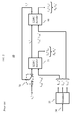
- FIG. 1 shows a prior art Parallel Concatenated Gallager Codes (PCGC) encoder
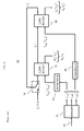
- FIG. 2 shows a prior art Parallel Concatenated Gallager Codes (PCGC) decoder
- FIG. 3 shows another prior art Parallel Concatenated Gallager Codes (PCGC) encoder
- FIG. 4 shows another prior art Parallel Concatenated Gallager Codes (PCGC) decoder
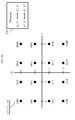
- FIG. 5 shows a prior art 8-PSK Gray mapped symbol constellation
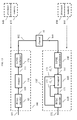
- FIG. 6 shows an illustrative high-level block diagram of an apparatus embodying the principles of the invention
- FIG. 7 shows an illustrative symbol mapper in accordance with the principles of the invention.
- FIG. 8 shows another illustrative symbol mapper in accordance with the principles of the invention.
- FIG. 9 shows a simulated Bit Error Rate (BER) performance for the mappers of FIGs. 7 and 8 ;
- FIG. 10 shows an illustrative 16 QAM Gray mapped symbol constellation and a mapping in accordance with the principles of the invention
- FIG. 11 shows an illustrative 64 QAM Gray mapped symbol constellation and a mapping in accordance with the principles of the invention
- FIG. 12 shows an illustrative flow chart in accordance with the principles of the invention.
- FIGs. 13-16 show other illustrative embodiments of a receiver in accordance with the principles of the invention.
- DMT Discrete Multitone
- OFDM Orthogonal Frequency Division Multiplexing
- COFDM Coded Orthogonal Frequency Division Multiplexing
- NTSC National Television Systems Committee
- PAL Phase Alternation Lines
- SECAM SEquential Couleur Avec Memoire
- ATSC Advanced Television Systems Committee
- DMB-T Digital Video Broadcasting-Terrestrial
- DV8 Framing structure, channel coding and modulation for digital terrestrial television and the Chinese Digital Television System (GB) 20600-2006 (Digital Multimedia Broadcasting - Terrestrial / Handheld (DMB-T/H))
- RF radio-frequency
- FFT fast fourier transform
- CSI channel state information estimators
- equalizers demodulators
- correlators correlators
- leak integrators squarers
- FIG. 5 a prior art 8-PSK (Phase Shift Keying) Gray mapped symbol constellation is shown, the x-axis representing the in-phase (I) values and the y-axis representing the quadrature (Q) values.
- the symbol constellation comprises 8 symbols, each symbol representing three bits, shown as Y 2 Y 1 Y 0 in FIG. 5 .
- adjacent symbols differ in only one bit position.
- Y 0 is the least reliable, while Y 1 and Y 2 have the same reliability and are more reliable that Y 0 (e.g., see " Reliability-Based Coded Modulation with Low-Density Parity-Check Codes", by Robert D. Maddock and Amir H. Banihashemi; IEEE Transactions on Communications, Vol. 54, No. 3, March 2006 ).
- FIG. 6 a high-level block diagram of a system in accordance with the principles of the invention is shown comprising a transmitter 100 and a receiver 150.
- the transmitter 100 transmits (or broadcasts) a signal 102 over a communications channel 10 to receiver 150.
- communications channel 10 affects the transmitted signal, e.g., noise, etc., this results in a signal 149 being received by receiver 150.
- Communications channel 10 represents wireless or wired communications channels.
- channel 10 represents an AWGN (Additive White Gaussian Noise) channel, though the invention is not so limited.
- AWGN Additional White Gaussian Noise
- Transmitter 100 comprises PCGC encoder 15 (as described above with respect to FIG. 1 ), a mapper 110 and 8-PSK modulator 120.
- Transmitter 100 is a processor-based system and includes one, or more, processors and associated memory as represented by processor 140 and memory 145 shown in the form of dashed boxes in FIG. 6 .
- computer programs, or software are stored in memory 145 for execution by processor 140 and, e.g., implement PCGC encoder 15.
- Processor 140 is representative of one, or more, stored-program control processors and these do not have to be dedicated to the transmitter function, e.g., processor 140 may also control other functions of transmitter 100.
- Memory 145 is representative of any storage device, e.g., random-access memory (RAM), read-only memory (ROM), etc.; may be internal and/or external to transmitter 100; and is volatile and/or non-volatile as necessary.
- Receiver 150 comprises 8-PSK demodulator 160, demapper 170 and PCGC decoder 60 (as described above with respect to FIG. 2 ). Like transmitter 100, receiver 150 is also a processor-based system and includes one, or more, processors and associated memory as represented by processor 190 and memory 195 shown in the form of dashed boxes in FIG. 6 . In this context, computer programs, or software, are stored in memory 195 for execution by processor 190 and, e.g., implement PCGC decoder 60. Processor 190 is representative of one, or more, stored-program control processors and these do not have to be dedicated to the receiver function, e.g., processor 190 may also control other functions of receiver 150. Memory 195 is representative of any storage device, e.g., random-access memory (RAM), read-only memory (ROM), etc.; may be internal and/or external to receiver 150; and is volatile and/or non-volatile as necessary.
- RAM random-access memory
- ROM read-only memory
- data as represented by input signal 101 (e.g., "X" from FIG. 1 ), is applied to PCGC encoder 15, which provides three bits representing a PCGC encoded signal 109.
- mapper 110 maps the PCGC encoded signal 109 to symbols of an 8-PSK symbol constellation (as shown in FIG. 5 ) such that 8-PSK modulator 120 selects the appropriate symbols for providing an 8-PSK modulated signal for transmission via signal 102.
- mapper 110 for mapping PCGC encoded bits to an 8-PSK symbol constellation (such as that shown in FIG. 5 ) in accordance with the principles of the invention is shown.
- the output of PCGC encoder 15 is the systemic information bits X (16), and parity bits V 1 (17) and V 2 (18).
- Mapper 110 maps the PCGC LDPC encoded signal 109 taking into account the different bit reliabilities in the associated 8-PSK symbol constellation of FIG. 5 .
- FIG. 7 shows that can be observed from FIG. 7 (with reference back to FIG.
- mapper 110 maps the systemic information bit X (16) and parity bit V 1 (17) to the more reliable positions in the 8-PSK symbol constellation, i.e., Y 2 (153) and Y 1 (152), respectively.
- the parity bit V 2 (18) is mapped to the less reliable bit position Y 0 (151).
- Signals 151, 152 and 153 comprise mapper output signal 111, which is applied to 8-PSK modulator 120 for use in selecting the symbols from the symbol constellation.
- the systemic information, X, and the parity bits V 1 are matched to the more reliable bit position of the symbol constellation.
- mapper 110 maps the systemic information bit X (16) to the less reliable bit position Y 0 (151).
- the parity bits V 1 (17) and V 2 (18) are mapped to the more reliable positions - Y 2 (153) and Y 1 (152), respectively.
- FIG. 9 a performance comparison of the simulated bit error rates (BERs) for communications systems using mapper 110 and mapper 110' is shown. It can be observed from FIG. 9 that by taking into account the bit reliabilities of the symbol constellation a further improvement in BER performance can be achieved as shown by the use of mapper 110 of FIG. 7 .
- BERs bit error rates
- signal 149 is received by 8-PSK demodulator 160 of receiver 150.
- 8-PSK demodulator 160 provides corresponding received bits Y R 2 Y R 1 Y R 0 to demapper 170 (via signal 161).
- Demapper 170 performs a complementary function to that of mapper 110 to provide received versions of PCGC encoded bits X, V1 and V2, i.e., X R , V R 1 and V R 2 to PCGC decoder 60 (via signal 171).
- demapper 170 provides the received versions of transmitted bits X, V 1 and V 2 as represented by LLR (log likelihood ratios) L CH 0 , L CH 1 and L CH 2 , respectively.
- LLR log likelihood ratios
- demapper 170 makes hard decisions as to the received symbol, i.e., selecting that constellation symbol that is closest in Euclidean distance to the received signal point.
- PCGC decoder 60 functions as described earlier and provides received error corrected systemic data 151.
- FIG. 10 shows an illustrative 16 Quadrature Amplitude Modulation (QAM) symbol constellation, Gray mapped, and a mapping 210 in accordance with the principles of the invention.
- QAM Quadrature Amplitude Modulation
- Y 0 and Y 1 are the least reliable bit positions
- the bit positions Y 2 and Y 3 have the same higher reliability as compared to bit positions Y 0 and Y 1 .
- mapping 210 the parity bits generated by the second component V 2 and a part of V 1 are mapped into the least reliable position Y 0 and Y 1 .
- mapping 210 ensures that all the systematic information bits are mapped to the higher reliability bit position in one constellation symbol and a number of the parity bits V 1 are also mapped to the high reliability bit position.
- the overall coderate is 1/3 and all the bits are mapped into 300 constellation symbols.
- the first 300 bits of X are mapped into Y 3 , then another 100 bits of X are mapped into Y 2 .
- the first 200 bits of V 1 are mapped into Y 2 and another 200 bits of V 1 are mapped into Y 1 .
- the first 100 bits of V 2 are mapped into Y 1 , and the rest of the bits of V 2 are mapped into Y 0 .
- this figure shows an illustrative 64 Quadrature Amplitude Modulation (QAM) symbol constellation, Gray mapped, and a mapping 310 in accordance with the principles of the invention.
- QAM Quadrature Amplitude Modulation
- Y 0 and Y 1 are the least reliable bit positions, and the bit positions Y 4 and Y 5 have the same higher reliability as compared to bit positions Y 0 and Y 1 .
- mapping 310 the parity bits generated by the second component V 2 are mapped into the least reliable position Y 0 and Y 1 .
- the parity bits generated by the first component V 1 are mapped into Y 2 and Y 3 .
- the systemic information, X is mapped into Y 4 and Y 5 .
- mapping 310 ensures that all the systematic information bits are mapped to the higher reliability bit position in one constellation symbol.
- a symbol constellation is identified, e.g., the 8-PSK symbol constellation of FIG. 5 or the 16-QAM symbol constellation of FIG. 10 .
- the bit reliabilities for the identified symbol constellation is determined for at least identifying those bits that are least reliable and those bits that are more reliable.
- the systemic data and at least a portion of the LDPC parity bits having better error performance are mapped to the more reliable bit positions of the identified symbol constellation.
- the systematic information bits and the parity bits generated by those component LDPC codes that have more strong correcting capability are mapped to the higher reliability bit positions in one constellation symbol.
- the decoding of received systematic information bits will have higher reliability and this also helps the convergence of PCGC decoding.
- the inventive concept was described in the context of 8-PSK, 16-QAM and 64-QAM, the invention is not so limited and can be easily extended to other higher order modulations where at least some of the constituent bits of the symbol constellation have different reliability. Further, although the inventive concept was described in the context of two LDPC encoders and two LDPC decoders, the inventive concept is not so limited an more LDPC encoders and decoders can be used.
- Receiver 150' is similar to receiver 150 described above except for demapper 605 and PCGC decoder 610.
- Demapper 605 uses LLR information from a previously decoded symbol to improve the selection of the next received symbol by demapper 605.
- Receiver 150' provides better performance than receiver 150 of FIG. 6 .
- demapper 605 receives LLR values associated with the previously decoded symbol.
- demapper 605 receives LLR values L e 1 (172) and L e 2 (173).
- demapper 605 now also takes into account information about the reliability of the previously decoded symbol from PCGC decoder 610.
- the following example illustrates the operation of demapper 605 with respect to Le 1 .
- the operation of demapper 605 with respect to Le 2 is similar and, as such, is not described herein.
- the magnitude of an LLR value represents the confidence in the decoded bits. The larger the LLR magnitude, the higher the confidence in the decoded bit.
- demapper 605 compares the value of Le 1 to a threshold value, M . If Le 1 is greater than M , then Le 1 represents a binary "1" value. If Le 1 is less than - M , then Le 1 represents a binary "0" value. Otherwise, the hard bit decision is uncertain and demapper 605 ignores the value of Le 1 and selects the received symbol based on Euclidean distance. The value for M is determined experientially. As noted earlier, in traditional demapping, the constellation symbol closest in Euclidean distance to the received signal point is selected as the received symbol. Referring now to FIG.
- demapper 605 uses the value of Le 1 to improve its decision. For example, if the result of the decision by PCGC decoder 610 shows that the value of Y 2 Y 1 has a high probability to be "1 0", then demapper 605 selects either symbol 101, or symbol 100 as illustrated by bracket 84 of FIG. 14 . It should be noted that the above description also applies to the use of interleaving in the PCGC signal.
- demapper 605 comprises demappers 605-1 and 605-2.
- Demapper 605-1 uses information (L e 1 ) from a previously decoded symbol (as described above) for providing L CH 0 and L CH 1 .
- demapper 605-2 uses information (L e 2 ) from a previously decoded symbol for providing L CH 0' and L CH 2 , as shown.
- demapper 605-2 may provide a different L CH 0 value as represented by L CH 0' .
- FIG. 16 illustrates an arrangement for a system that utilizes interleaving. It should be observed that interleavers 620 and 625 are required to take into account that signal 161 is interleaved.
Landscapes
- Engineering & Computer Science (AREA)
- Physics & Mathematics (AREA)
- Probability & Statistics with Applications (AREA)
- Theoretical Computer Science (AREA)
- Computer Networks & Wireless Communication (AREA)
- Signal Processing (AREA)
- Digital Transmission Methods That Use Modulated Carrier Waves (AREA)
Abstract
Description
- The present invention generally relates to communications systems and, more particularly, to a receiver.
- Low-density parity-check (LDPC) codes were first introduced by R. G. Gallager (e.g., see Gallager, R. G., Low Density Parity Check Codes, Monograph, M.I.T. Press, 1963) as a family of block codes characterized by a sparse parity-check matrix, with each row in the matrix representing a coefficient in a parity-check equation. R. G. Gallager showed that random LDPC codes are asymptotically good for binary symmetric channels (BSC) and that they achieve small error probabilities for rates bounded away from zero as the block length increases. Compared to Turbo codes, which have a high error floor, LDPC codes usually have a low error floor, i.e., for an increase in the number of iterations there is a relatively low bit error rate (BER). As such, many communication standards adopt LDPC for channel coding. However, good performance of LDPC codes usually requires a long code length, which leads to long data delay and increased decoding complexity.
- In this regard, the use of Parallel Concatenated Gallager Codes (PCGC) in LDPC coding has been proposed in order to reduce the data delay and decoding complexity of LDPC codes. This sort of LDPC coding uses good LDPC codes in the well known turbo code structure to break the fairly complex encoding and decoding of a long code into steps.
- An example of a prior
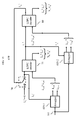
art PCGC encoder 15 is shown inFIG. 1 . The parameter X (14) represents the systemic information bits, i.e., the data to be LDPC encoded. This data is applied toPCGC encoder 15, which comprises a number of LDPC encoders arranged in parallel, as represented by afirst LDPC encoder 35 and asecond LDPC encoder 40. Thefirst LDPC encoder 35 generates parity bits V1 (17) and thesecond LDPC encoder 40 generates parity bits V2 (18). As such, the output ofPCGC encoder 15 is the systemic information bits X (16), and parity bits V1 (17) and V2 (18). - In the arrangement shown in
FIG. 1 , an interleaver is not used between the two LDPC encoders. The two LDPC encoders implement different LDPC codes having different error performance. The LDPC code implemented by thefirst LDPC encoder 35 has better error performance than that of the LDPC coded implemented by thesecond LDPC encoder 40 at a low Energy per bit to noise power spectral density ratio (Eb/N0). The Eb/N0 is a normalized signal-to-noise ratio (SNR), also known as the SNR per bit. However, at a high Eb/N0, the LDPC code implemented by thesecond LDPC encoder 40 has better decoding convergence and performs better than the LDPC code ofLDPC encoder 35 due to the smaller undetected errors. In other words, each component LDPC code ofPCGC encoder 15 has a different Mean Column Weight (MCW) to get different channel coding gains. - A prior
art PCGC decoder 60 is shown inFIG. 2 . In a complementary fashion to PCGCencoder 15 ofFIG. 1 , PCGCdecoder 60 comprises afirst LDPC decoder 75 and asecond LDPC decoder 80. Also shown inFIG. 2 isdemapper 55, which processes a receivedsignal 54 to provide received versions of X, V1 and V2 as represented by LLR (log likelihood ratios) LCH 0, LCH 1 and LCH 2, respectively. As known in the art,demapper 55 makes hard decisions as to the received symbol, i.e., selecting that constellation symbol that is closest in Euclidean distance to the received signal point.First LDPC decoder 75 processes LCH 0 and LCH 1 and thesecond LDPC decoder 80 processes LCH 0 and LCH 2. A super iteration is defined as the process of exchanging information between the two LDPC decoders. In each super iteration, each component decoder performs a number of local iterations before passing any information to the other component decoder. In the first super iteration,LDPC decoder 75 computes the a posteriori LLR (log likelihood ratio) value Le 1 of the corresponding coded bits using received sequences LCH 0 and LCH 1 with no a priori information since the information bits are equally likely to be a -1 or a 1. This is represented inFIG. 2 byswitch 70 being set to a value of Le 2=0. Thesecond LDPC decoder 80 then computes the a posteriori probability LLR value Le 2 using the received sequences LCH 0 and LCH 2 along with the extrinsic information Le 1 available from the first decoder, as a priori information. On subsequent iterations, thefirst LDPC decoder 75 uses the extrinsic information generated by thesecond LDPC decoder 8 0, i.e., Le 2 (via switch 70), as a priori information to compute the a posteriori LLR value Le 1. The process of exchanging information between the component decoders continues until both decoders converge to valid codewords, or a maximum number of super iterations is reached.LDPC decoder 75 provides output signals Lo 0 and Lo 1, representative of error corrected received versions of systematic information bits, XR and parity bit VR 1, respectively; andLDPC decoder 80 provides output signals Lo 0 and Lo 2, representative of error corrected received versions of systematic information bits, XR and parity bit VR 2, respectively. As is known in the art, the two component LDPC decoders both provide the systematic information bits, XR. However, should the value for XR provided byLDPC decoder 80 be different from the value for XR provided byLDPC decoder 75, the value for XR fromLDPC decoder 75 is only used sinceLDPC decoder 75 is associated with the LDPC code having more error-correcting capability. - Turning briefly to
FIGs. 3 and4 , these figures show prior art arrangements of a PCGC encoder and a PCGC decoder using interleavers. The arrangement shown inFIG. 3 is similar to the arrangement shown inFIG. 1 , except thatinterleavers PCGC encoder 15 as shown before providing the output signals: systemic information bits X (16), and parity bits V1 (17) and V2 (18). Likewise, the arrangement shown inFIG. 4 is similar to the arrangement shown inFIG. 2 except thatdeinterleavers demapper 55 as shown during the decoding process. - Since the need for more and more channel capacity is increasing in today's communications systems, the design of a channel code is often required to use a high order modulation. We have observed that one can match PCGC LDPC coding to a higher order modulation and get very good performance along with high spectrum efficiency.
- Therefore, and in accordance with the principles of the invention, a parallel concatenated gallager code encoder provides at least one data bit, a first parity bit and a second parity bit, where the first parity bit is associated with a low density parity check code having a higher error correcting capability than a low density parity check code associated with the second parity bit; a modulator provides a modulated signal using a symbol constellation having at least eight symbols, each symbol associated with at least three bits, where at least one of the three bits has less reliability than the remaining bits; and a mapper maps the at least one data bit to those bit positions of a symbol having higher reliability than the at least one bit position having less reliability and maps the second parity bit to the at least one bit position having less reliability.
- In an illustrative embodiment of the invention, the parallel concatenated gallager code encoder comprises a parallel arrangement of at least two low density parity check encoders, where at least one low density parity encoder provides the first parity bit and the other low density parity check encoders provides the second parity bit and the symbol constellation is an 8-phase shift keying symbol constellation.
- In another illustrative embodiment of the invention, the parallel concatenated gallager code encoder comprises a parallel arrangement of at least two low density parity check encoders, where at least one low density parity encoder provides the first parity bit and the other low density parity check encoders provides the second parity bit and the symbol constellation is a 16-quadrature amplitude modulation symbol constellation.
- In another illustrative embodiment of the invention, the parallel concatenated gallager code encoder comprises a parallel arrangement of at least two low density parity check encoders, where at least one low density parity encoder provides the first parity bit and the other low density parity check encoders provides the second parity bit and the symbol constellation is a 64-quadrature amplitude modulation symbol constellation.
- In view of the above, and as will be apparent from reading the detailed description, other embodiments and features are also possible and fall within the principles of the invention.
-
FIG. 1 shows a prior art Parallel Concatenated Gallager Codes (PCGC) encoder; -
FIG. 2 shows a prior art Parallel Concatenated Gallager Codes (PCGC) decoder; -
FIG. 3 shows another prior art Parallel Concatenated Gallager Codes (PCGC) encoder; -
FIG. 4 shows another prior art Parallel Concatenated Gallager Codes (PCGC) decoder; -
FIG. 5 shows a prior art 8-PSK Gray mapped symbol constellation; -
FIG. 6 shows an illustrative high-level block diagram of an apparatus embodying the principles of the invention; -
FIG. 7 shows an illustrative symbol mapper in accordance with the principles of the invention; -
FIG. 8 shows another illustrative symbol mapper in accordance with the principles of the invention; -
FIG. 9 shows a simulated Bit Error Rate (BER) performance for the mappers ofFIGs. 7 and8 ; -
FIG. 10 shows an illustrative 16 QAM Gray mapped symbol constellation and a mapping in accordance with the principles of the invention; -
FIG. 11 shows an illustrative 64 QAM Gray mapped symbol constellation and a mapping in accordance with the principles of the invention; -
FIG. 12 shows an illustrative flow chart in accordance with the principles of the invention; and -
FIGs. 13-16 show other illustrative embodiments of a receiver in accordance with the principles of the invention. - Other than the inventive concept, the elements shown in the figures are well known and will not be described in detail. For example, other than the inventive concept, familiarity with Discrete Multitone (DMT) transmission (also referred to as Orthogonal Frequency Division Multiplexing (OFDM) or Coded Orthogonal Frequency Division Multiplexing (COFDM)) is assumed and not described herein. Also, familiarity with television broadcasting, receivers and video encoding is assumed and is not described in detail herein. For example, other than the inventive concept, familiarity with current and proposed recommendations for TV standards such as NTSC (National Television Systems Committee), PAL (Phase Alternation Lines), SECAM (SEquential Couleur Avec Memoire), ATSC (Advanced Television Systems Committee) (ATSC), Digital Video Broadcasting (DVB), Digital Video Broadcasting-Terrestrial (DVB-T) (e.g., see ETSI EN 300 744 V1.4.1 (2001-01), Digital Video Broadcasting (DV8); Framing structure, channel coding and modulation for digital terrestrial television and the Chinese Digital Television System (GB) 20600-2006 (Digital Multimedia Broadcasting - Terrestrial / Handheld (DMB-T/H)) is assumed. Likewise, other than the inventive concept, other transmission concepts such as eight-level vestigial sideband (8-VSB), Phase-Shift Keying (PSK), Quadrature Amplitude Modulation (QAM), and receiver components such as a radio-frequency (RF) front-end, or receiver section, such as a low noise block, tuners, and down converters; along with fast fourier transform (FFT) elements, spectrum shifters, channel state information (CSI) estimators, equalizers, demodulators, correlators, leak integrators and squarers is assumed. Further, other than the inventive concept, familiarity with processing signals, such as forming channel state information, is assumed and not described herein. Similarly, other than the inventive concept, formatting and encoding methods (such as Moving Picture Expert Group (MPEG)-2 Systems Standard (ISO/IEC 13818-1)) for generating transport bit streams are well-known and not described herein. It should also be noted that the inventive concept may be implemented using conventional programming techniques, which, as such, will not be described herein. In this regard, the embodiments described herein may be implemented in the analog or digital domains. Finally, like-numbers on the figures represent similar elements.
- Turning now to
FIG. 5 , a prior art 8-PSK (Phase Shift Keying) Gray mapped symbol constellation is shown, the x-axis representing the in-phase (I) values and the y-axis representing the quadrature (Q) values. In 8-PSK, the symbol constellation comprises 8 symbols, each symbol representing three bits, shown as Y2Y1Y0 inFIG. 5 . For example, as illustrated by the dotted line, thesymbol 21 represents thebits pattern 010, where Y2=0, Y1=1, and Y0=0, with Y0 being the least significant bit position. As known in the art, in a Gray mapped symbol constellation, adjacent symbols differ in only one bit position. It is also known that different bits positions in a symbol have different reliabilities. For the 8-PSK symbol constellation ofFIG. 5 , Y0 is the least reliable, while Y1 and Y2 have the same reliability and are more reliable that Y0 (e.g., see "Reliability-Based Coded Modulation with Low-Density Parity-Check Codes", by Robert D. Maddock and Amir H. Banihashemi; IEEE Transactions on Communications, Vol. 54, No. 3, March 2006). - Since the need for more and more channel capacity is increasing in today's communications systems, the design of a channel code is often required to use a high order modulation. In this regard, we have observed that one can match PCGC LDPC coding to a higher order modulation by taking into account the different bit reliabilities in the associated symbol constellation and get very good performance along with high spectrum efficiency.
- Referring now to
FIG. 6 , a high-level block diagram of a system in accordance with the principles of the invention is shown comprising atransmitter 100 and areceiver 150. Thetransmitter 100 transmits (or broadcasts) asignal 102 over acommunications channel 10 toreceiver 150. Sincecommunications channel 10 affects the transmitted signal, e.g., noise, etc., this results in asignal 149 being received byreceiver 150.Communications channel 10 represents wireless or wired communications channels. For purposes of this description,channel 10 represents an AWGN (Additive White Gaussian Noise) channel, though the invention is not so limited. -
Transmitter 100 comprises PCGC encoder 15 (as described above with respect toFIG. 1 ), amapper 110 and 8-PSK modulator 120.Transmitter 100 is a processor-based system and includes one, or more, processors and associated memory as represented byprocessor 140 andmemory 145 shown in the form of dashed boxes inFIG. 6 . In this context, computer programs, or software, are stored inmemory 145 for execution byprocessor 140 and, e.g., implementPCGC encoder 15.Processor 140 is representative of one, or more, stored-program control processors and these do not have to be dedicated to the transmitter function, e.g.,processor 140 may also control other functions oftransmitter 100.Memory 145 is representative of any storage device, e.g., random-access memory (RAM), read-only memory (ROM), etc.; may be internal and/or external totransmitter 100; and is volatile and/or non-volatile as necessary. -
Receiver 150 comprises 8-PSK demodulator 160,demapper 170 and PCGC decoder 60 (as described above with respect toFIG. 2 ). Liketransmitter 100,receiver 150 is also a processor-based system and includes one, or more, processors and associated memory as represented byprocessor 190 andmemory 195 shown in the form of dashed boxes inFIG. 6 . In this context, computer programs, or software, are stored inmemory 195 for execution byprocessor 190 and, e.g., implementPCGC decoder 60.Processor 190 is representative of one, or more, stored-program control processors and these do not have to be dedicated to the receiver function, e.g.,processor 190 may also control other functions ofreceiver 150.Memory 195 is representative of any storage device, e.g., random-access memory (RAM), read-only memory (ROM), etc.; may be internal and/or external toreceiver 150; and is volatile and/or non-volatile as necessary. - Returning to
transmitter 100, data, as represented by input signal 101 (e.g., "X" fromFIG. 1 ), is applied toPCGC encoder 15, which provides three bits representing a PCGC encodedsignal 109. In accordance with the principles of the invention,mapper 110 maps the PCGC encodedsignal 109 to symbols of an 8-PSK symbol constellation (as shown inFIG. 5 ) such that 8-PSK modulator 120 selects the appropriate symbols for providing an 8-PSK modulated signal for transmission viasignal 102. - Referring now to
FIG. 7 , anillustrative mapper 110 for mapping PCGC encoded bits to an 8-PSK symbol constellation (such as that shown inFIG. 5 ) in accordance with the principles of the invention is shown. As described earlier, the output ofPCGC encoder 15 is the systemic information bits X (16), and parity bits V1 (17) and V2 (18).Mapper 110 maps the PCGC LDPC encodedsignal 109 taking into account the different bit reliabilities in the associated 8-PSK symbol constellation ofFIG. 5 . In particular, and as can be observed fromFIG. 7 (with reference back toFIG. 5 ),mapper 110 maps the systemic information bit X (16) and parity bit V1 (17) to the more reliable positions in the 8-PSK symbol constellation, i.e., Y2 (153) and Y1 (152), respectively. The parity bit V2 (18) is mapped to the less reliable bit position Y0 (151).Signals mapper output signal 111, which is applied to 8-PSK modulator 120 for use in selecting the symbols from the symbol constellation. Thus, the systemic information, X, and the parity bits V1 (representing the error code with better error performance) are matched to the more reliable bit position of the symbol constellation. - As described above, a PCGC encoder is mapped to a symbol constellation in such a way as to take advantage of the different bit reliabilities of a symbol constellation. This is further illustrated in a different embodiment of
mapper 110 shown inFIG. 8 as mapper 110'. Here, mapper 110' maps the systemic information bit X (16) to the less reliable bit position Y0 (151). The parity bits V1 (17) and V2 (18) are mapped to the more reliable positions - Y2 (153) and Y1 (152), respectively. - Referring now to
FIG. 9 , a performance comparison of the simulated bit error rates (BERs) for communicationssystems using mapper 110 and mapper 110' is shown. It can be observed fromFIG. 9 that by taking into account the bit reliabilities of the symbol constellation a further improvement in BER performance can be achieved as shown by the use ofmapper 110 ofFIG. 7 . - It should be noted that the above description of the inventive concept applies also to the case where interleaving is used, i.e., the systemic information bit X (16), and parity bit V1 (17) and V2 (18) are first interleaved as shown in
FIG. 3 . - Turning back now to
FIG. 6 , signal 149 is received by 8-PSK demodulator 160 ofreceiver 150. 8-PSK demodulator 160 provides corresponding received bits YR 2YR 1YR 0 to demapper 170 (via signal 161).Demapper 170 performs a complementary function to that ofmapper 110 to provide received versions of PCGC encoded bits X, V1 and V2, i.e., XR, VR 1 and VR 2 to PCGC decoder 60 (via signal 171). In particular,demapper 170 provides the received versions of transmitted bits X, V1 and V2 as represented by LLR (log likelihood ratios) LCH 0, LCH 1 and LCH 2, respectively. As known in the art,demapper 170 makes hard decisions as to the received symbol, i.e., selecting that constellation symbol that is closest in Euclidean distance to the received signal point.PCGC decoder 60 functions as described earlier and provides received error correctedsystemic data 151. - It should be noted that the inventive concept is applicable to other types of higher order modulations.
FIG. 10 shows an illustrative 16 Quadrature Amplitude Modulation (QAM) symbol constellation, Gray mapped, and amapping 210 in accordance with the principles of the invention. In a 16-QAM symbol constellation as shown inFIG. 10 , Y0 and Y1 are the least reliable bit positions, and the bit positions Y2 and Y3 have the same higher reliability as compared to bit positions Y0 and Y1. Inmapping 210, the parity bits generated by the second component V2 and a part of V1 are mapped into the least reliable position Y0 and Y1. The remaining part of V1 and all of the systematic information bits X are mapped into Y2, Y3. Thus, similar to the 8-PSK mapping described above, mapping 210 ensures that all the systematic information bits are mapped to the higher reliability bit position in one constellation symbol and a number of the parity bits V1 are also mapped to the high reliability bit position. In particular, when bits X, V1 and V2 are mapped into the symbol constellation, consecutive bit-mapping is used. For example, ifLDPC encoder 35 iscode rate 1/2, (n.k)=(800,400), then X=400, V1=400; and ifLDPC encoder 40 is alsocode rate 1/2, (n.k)=(800,400), then V2=400. As a result, the overall coderate is 1/3 and all the bits are mapped into 300 constellation symbols. The first 300 bits of X are mapped into Y3, then another 100 bits of X are mapped into Y2. Then, the first 200 bits of V1 are mapped into Y2 and another 200 bits of V1 are mapped into Y1. Finally, the first 100 bits of V2 are mapped into Y1, and the rest of the bits of V2 are mapped into Y0. - Referring briefly to
FIG. 11 , this figure shows an illustrative 64 Quadrature Amplitude Modulation (QAM) symbol constellation, Gray mapped, and amapping 310 in accordance with the principles of the invention. In a 64-QAM symbol constellation as shown inFIG. 10 , Y0 and Y1 are the least reliable bit positions, and the bit positions Y4 and Y5 have the same higher reliability as compared to bit positions Y0 and Y1. Inmapping 310, the parity bits generated by the second component V2 are mapped into the least reliable position Y0 and Y1. The parity bits generated by the first component V1 are mapped into Y2 and Y3. Finally, the systemic information, X, is mapped into Y4 and Y5. Thus, similar to the 8-PSK mapping described above, mapping 310 ensures that all the systematic information bits are mapped to the higher reliability bit position in one constellation symbol. - Turning now to
FIG. 12 , an illustrative flow chart in accordance with the principles of the invention is shown. Instep 505, a symbol constellation is identified, e.g., the 8-PSK symbol constellation ofFIG. 5 or the 16-QAM symbol constellation ofFIG. 10 . Instep 515, the bit reliabilities for the identified symbol constellation is determined for at least identifying those bits that are least reliable and those bits that are more reliable. Instep 520, the systemic data and at least a portion of the LDPC parity bits having better error performance are mapped to the more reliable bit positions of the identified symbol constellation. Thus, the systematic information bits and the parity bits generated by those component LDPC codes that have more strong correcting capability are mapped to the higher reliability bit positions in one constellation symbol. As such, in a corresponding receiver, the decoding of received systematic information bits will have higher reliability and this also helps the convergence of PCGC decoding. - As described above, and in accordance with the principles of the invention, by carefully choosing the mapping strategy between PCGC encoded bits and constellation symbols the combination between PCGC coding and multilevel modulation can be matched to get very good performance along with high spectrum efficiency and yet have low decoding complexity. Although the inventive concept was described in the context of 8-PSK, 16-QAM and 64-QAM, the invention is not so limited and can be easily extended to other higher order modulations where at least some of the constituent bits of the symbol constellation have different reliability. Further, although the inventive concept was described in the context of two LDPC encoders and two LDPC decoders, the inventive concept is not so limited an more LDPC encoders and decoders can be used.
- Referring now to
FIG. 13 another illustrative receiver in accordance with the principles of the invention is shown. Receiver 150' is similar toreceiver 150 described above except fordemapper 605 andPCGC decoder 610.Demapper 605 uses LLR information from a previously decoded symbol to improve the selection of the next received symbol bydemapper 605. Receiver 150' provides better performance thanreceiver 150 ofFIG. 6 . In particular, after the first iteration ofPCGC decoder 610,demapper 605 receives LLR values associated with the previously decoded symbol. In this example,demapper 605 receives LLR values Le 1 (172) and Le 2 (173). Thus, in making hard decisions as to the actual received symbol,demapper 605 now also takes into account information about the reliability of the previously decoded symbol fromPCGC decoder 610. The following example illustrates the operation ofdemapper 605 with respect to Le1. The operation ofdemapper 605 with respect to Le2 is similar and, as such, is not described herein. - The magnitude of an LLR value represents the confidence in the decoded bits. The larger the LLR magnitude, the higher the confidence in the decoded bit. In this regard,
demapper 605 compares the value of Le1 to a threshold value, M. If Le1 is greater than M, then Le1 represents a binary "1" value. If Le1 is less than -M, then Le1 represents a binary "0" value. Otherwise, the hard bit decision is uncertain anddemapper 605 ignores the value of Le1 and selects the received symbol based on Euclidean distance. The value for M is determined experientially. As noted earlier, in traditional demapping, the constellation symbol closest in Euclidean distance to the received signal point is selected as the received symbol. Referring now toFIG. 14 , assume that a received signal point, x (81) is received by receiver 150'. In traditional demapping, either symbol 001 (82) or symbol 000 (83) would be selected by the demapper. However, now,demapper 605 uses the value of Le1 to improve its decision. For example, if the result of the decision byPCGC decoder 610 shows that the value of Y2 Y1 has a high probability to be "1 0", then demapper 605 selects eithersymbol 101, orsymbol 100 as illustrated bybracket 84 ofFIG. 14 . It should be noted that the above description also applies to the use of interleaving in the PCGC signal. - Additional illustrations of the arrangement of
decoder 605 andPCGC decoder 610 are shown inFIGs. 15 and16 .FIG. 15 illustrates an arrangement without interleaving; whileFIG. 16 illustrates an arrangement with interleaving. As can be observed inFIG. 15 ,demapper 605 comprises demappers 605-1 and 605-2. Demapper 605-1 uses information (Le 1) from a previously decoded symbol (as described above) for providing LCH 0 and LCH 1. Likewise, demapper 605-2 uses information (Le 2) from a previously decoded symbol for providing LCH 0' and LCH 2, as shown. It should be noted that demapper 605-2 may provide a different LCH 0 value as represented by LCH 0'.FIG. 16 illustrates an arrangement for a system that utilizes interleaving. It should be observed that interleavers 620 and 625 are required to take into account that signal 161 is interleaved. - In view of the above, the foregoing merely illustrates the principles of the invention and it will thus be appreciated that those skilled in the art will be able to devise numerous alternative arrangements which, although not explicitly described herein, embody the principles of the invention and are within its spirit and scope. For example, although illustrated in the context of separate functional elements, these functional elements may be embodied in one, or more, integrated circuits (ICs). Similarly, although shown as separate elements, any or all of the elements (e.g., of
FIG. 6 ) may be implemented in a stored-program-controlled processor, e.g., a digital signal processor, which executes associated software. Further, the principles of the invention are applicable to other types of communications systems, e.g., satellite, Wireless-Fidelity (Wi-Fi), cellular, etc. Indeed, the inventive concept is also applicable to stationary or mobile receivers. It is therefore to be understood that numerous modifications may be made to the illustrative embodiments and that other arrangements may be devised without departing from the spirit and scope of the present invention as defined by the appended claims.
Claims (11)
- Apparatus comprising:a parallel concatenated gallager code encoder for providing at least one data bit, a first parity bit and a second parity bit, where the first parity bit is associated with a low density parity check code having a higher error correcting capability than a low density parity check code associated with the second parity bit;a modulator for providing a modulated signal using a symbol constellation having at least eight symbols, each symbol associated with at least three bits, where at least one of the three bits has less reliability than the remaining bits; anda mapper for mapping the at least one data bit to those bit positions of a symbol having higher reliability than the at least one bit position having less reliability and mapping the second parity bit to the at least one bit position having less reliability.
- The apparatus of claim 1, wherein the mapper maps the first parity bit to those bit positions of a symbol having higher reliability than the at least one bit position having less reliability.
- The apparatus of claim 1, wherein the parallel concatenated gallager code encoder comprises:a parallel arrangement of at least two low density parity check encoders, where at least one low density parity encoder provides the first parity bit and the other low density parity check encoders provides the second parity bit.
- The apparatus of claim 1, wherein the symbol constellation is an 8-phase shift keying symbol constellation.
- The apparatus of claim 1, wherein the symbol constellation is a 16-quadrature amplitude modulation symbol constellation.
- The apparatus of claim 1, wherein the symbol constellation is a 64-quadrature amplitude modulation symbol constellation.
- A method comprising:encoding data using a parallel concatenated gallager code for providing at least one data bit, a first parity bit and a second parity bit, where the first parity bit is associated with a low density parity check code having a higher error correcting capability than a low density parity check code associated with the second parity bit;providing a modulated signal using a symbol constellation having at least eight symbols, each symbol associated with at least three bits, where at least one of the three bits has less reliability than the remaining bits; andmapping (a) the at least one data bit to those bit positions of a symbol having higher reliability than the at least one bit position having less reliability and (b) the second parity bit to the at least one bit position having less reliability.
- The method of claim 7, wherein the mapping step maps the first parity bit to those bit positions of a symbol having higher reliability than the at least one bit position having less reliability.
- The method of claim 7, wherein the symbol constellation is an 8-phase shift keying symbol constellation.
- The method of claim 7, wherein the symbol constellation is a 16-quadrature amplitude modulation symbol constellation.
- The method of claim 7, wherein the symbol constellation is a 64-quadrature amplitude modulation symbol constellation.
Priority Applications (2)
| Application Number | Priority Date | Filing Date | Title |
|---|---|---|---|
| EP08305147A EP2124344A1 (en) | 2008-05-05 | 2008-05-05 | Coded modulation with parallel concatenated Gallager codes |
| PCT/IB2009/005433 WO2009136247A1 (en) | 2008-05-05 | 2009-04-29 | Coded modulation with parallel concatenated gallager codes |
Applications Claiming Priority (1)
| Application Number | Priority Date | Filing Date | Title |
|---|---|---|---|
| EP08305147A EP2124344A1 (en) | 2008-05-05 | 2008-05-05 | Coded modulation with parallel concatenated Gallager codes |
Publications (1)
| Publication Number | Publication Date |
|---|---|
| EP2124344A1 true EP2124344A1 (en) | 2009-11-25 |
Family
ID=40042786
Family Applications (1)
| Application Number | Title | Priority Date | Filing Date |
|---|---|---|---|
| EP08305147A Withdrawn EP2124344A1 (en) | 2008-05-05 | 2008-05-05 | Coded modulation with parallel concatenated Gallager codes |
Country Status (2)
| Country | Link |
|---|---|
| EP (1) | EP2124344A1 (en) |
| WO (1) | WO2009136247A1 (en) |
Cited By (5)
| Publication number | Priority date | Publication date | Assignee | Title |
|---|---|---|---|---|
| US20130173982A1 (en) * | 2011-12-29 | 2013-07-04 | Korea Advanced Institute Of Science And Technology (Kaist) | Method of decoding ldpc code for producing several different decoders using parity-check matrix of ldpc code and ldpc code system including the same |
| CN103560798A (en) * | 2013-08-16 | 2014-02-05 | 北京邮电大学 | Encoding and decoding method of new type LDPC-based hybrid Turbo structure code |
| WO2015088872A1 (en) * | 2013-12-11 | 2015-06-18 | Tyco Electronics Subsea Communications Llc | System and method for cycle slip correction |
| EP3188451A4 (en) * | 2014-09-25 | 2017-09-06 | Huawei Technologies Co., Ltd. | Coding and modulation method and device which support robust channel (rc) |
| EP3682570A1 (en) * | 2017-09-13 | 2020-07-22 | Ciena Corporation | Forward error correction with compression coding |
Families Citing this family (2)
| Publication number | Priority date | Publication date | Assignee | Title |
|---|---|---|---|---|
| CN108809522B (en) * | 2018-07-09 | 2021-09-14 | 上海大学 | Method for realizing multi-code deep learning decoder |
| CN115664431B (en) * | 2022-11-03 | 2026-02-10 | 哈尔滨工业大学 | A system for constructing globally coupled low-density parity check codes based on nested structures. |
Citations (2)
| Publication number | Priority date | Publication date | Assignee | Title |
|---|---|---|---|---|
| EP1531552A1 (en) * | 2003-11-14 | 2005-05-18 | Samsung Electronics Co., Ltd. | Channel encoding/decoding apparatus and method using a parallel concatenated low density parity check code |
| US20050149841A1 (en) * | 2003-11-14 | 2005-07-07 | Samsung Electronics Co., Ltd. | Channel coding/decoding apparatus and method using a parallel concatenated low density parity check code |
-
2008
- 2008-05-05 EP EP08305147A patent/EP2124344A1/en not_active Withdrawn
-
2009
- 2009-04-29 WO PCT/IB2009/005433 patent/WO2009136247A1/en not_active Ceased
Patent Citations (2)
| Publication number | Priority date | Publication date | Assignee | Title |
|---|---|---|---|---|
| EP1531552A1 (en) * | 2003-11-14 | 2005-05-18 | Samsung Electronics Co., Ltd. | Channel encoding/decoding apparatus and method using a parallel concatenated low density parity check code |
| US20050149841A1 (en) * | 2003-11-14 | 2005-07-07 | Samsung Electronics Co., Ltd. | Channel coding/decoding apparatus and method using a parallel concatenated low density parity check code |
Non-Patent Citations (8)
| Title |
|---|
| BEHAIRY H ET AL: "Parallel concatenated Gallager codes for CDMA applications", PROC., IEEE GLOBAL TELECOMMUNICATIONS CONFERENCE, GLOBECOM 2001, SAN ANTONIO, TX, 25 November 2001 (2001-11-25) - 29 November 2001 (2001-11-29), pages 1002 - 1006, XP001099255, ISBN: 978-0-7803-7206-1 * |
| BEHAIRY H ET AL: "Parallel concatenated Gallager codes", ELECTRONICS LETTERS, IEE STEVENAGE, GB, vol. 36, no. 24, 23 November 2000 (2000-11-23), pages 2025 - 2026, XP006015951, ISSN: 0013-5194 * |
| FANG WANG ET AL.: "Design and code optimization of parallel concatenated Gallager codes", PROC., IEEE 18TH INTERNATIONAL SYMPOSIUM ON PERSONAL, INDOOR AND MOBILE RADIO COMMUNICATIONS, ATHENS, GREECE, 3 September 2007 (2007-09-03) - 7 September 2009 (2009-09-07), pages 1312 - 1316, XP002507316, ISBN: 978-1-4244-1143-6 * |
| GALLAGER, R. G.: "Low Density Parity Check Codes, Monograph", 1963, M.I.T. PRESS |
| GOUNAI S ET AL: "Mapping for Iterative MMSE-SIC with Belief Propagation", PROC., IEEE INTERNATIONAL CONFERENCE ON COMMUNICATION, ICC'07, GLASGOW, SCOTLAND, 24 June 2007 (2007-06-24) - 28 June 2007 (2007-06-28), pages 4885 - 4890, XP031126439, ISBN: 978-1-4244-0353-0 * |
| HYEONG-GUN JOO ET AL.: "Adaptive bit-reliability mapping for LDPC-coded high-order modulation systems", PROC., IEEE 65TH VEHICULAR TECHNOLOGY CONFERENCE, DUBLIN, IRELAND, 22 April 2007 (2007-04-22) - 25 April 2007 (2007-04-25), pages 1539 - 1543, XP002507317, ISBN: 1-4244-0265-4 * |
| LI Y ET AL: "Bit-reliability mapping in LDPC-coded modulation systems", IEEE COMMUNICATIONS LETTERS, IEEE SERVICE CENTER, PISCATAWAY, NJ, US, vol. 9, no. 1, 1 January 2005 (2005-01-01), pages 1 - 03, XP001211457, ISSN: 1089-7798 * |
| ROBERT D. MADDOCK; AMIR H. BANIHASHEMI: "Reliability-Based Coded Modulation with Low-Density Parity-Check Codes", IEEE TRANSACTIONS ON COMMUNICATIONS, vol. 54, no. 3, March 2006 (2006-03-01), XP002507532, DOI: doi:10.1109/TCOMM.2006.869865 |
Cited By (12)
| Publication number | Priority date | Publication date | Assignee | Title |
|---|---|---|---|---|
| US20130173982A1 (en) * | 2011-12-29 | 2013-07-04 | Korea Advanced Institute Of Science And Technology (Kaist) | Method of decoding ldpc code for producing several different decoders using parity-check matrix of ldpc code and ldpc code system including the same |
| US8826096B2 (en) * | 2011-12-29 | 2014-09-02 | Korea Advanced Institute Of Science And Technology | Method of decoding LDPC code for producing several different decoders using parity-check matrix of LDPC code and LDPC code system including the same |
| CN103560798A (en) * | 2013-08-16 | 2014-02-05 | 北京邮电大学 | Encoding and decoding method of new type LDPC-based hybrid Turbo structure code |
| CN103560798B (en) * | 2013-08-16 | 2016-12-28 | 北京邮电大学 | A kind of novel volume of mixed type Turbo constructive code based on LDPC, interpretation method |
| WO2015088872A1 (en) * | 2013-12-11 | 2015-06-18 | Tyco Electronics Subsea Communications Llc | System and method for cycle slip correction |
| US9336079B2 (en) | 2013-12-11 | 2016-05-10 | Tyco Electronics Subsea Communications Llc | System and method for cycle slip correction |
| CN105794133A (en) * | 2013-12-11 | 2016-07-20 | 泰科电子海底通信有限责任公司 | System and Method for Cycle Slip Correction |
| CN105794133B (en) * | 2013-12-11 | 2020-01-10 | 萨伯康姆有限责任公司 | System and method for cycle slip correction |
| EP3188451A4 (en) * | 2014-09-25 | 2017-09-06 | Huawei Technologies Co., Ltd. | Coding and modulation method and device which support robust channel (rc) |
| US10263751B2 (en) | 2014-09-25 | 2019-04-16 | Huawei Technologies Co., Ltd. | Robust channel RC-supporting coding and modulation method and apparatus |
| EP3614648A1 (en) * | 2014-09-25 | 2020-02-26 | Huawei Technologies Co., Ltd. | Robust channel rc-supporting coding and modulation method and apparatus |
| EP3682570A1 (en) * | 2017-09-13 | 2020-07-22 | Ciena Corporation | Forward error correction with compression coding |
Also Published As
| Publication number | Publication date |
|---|---|
| WO2009136247A1 (en) | 2009-11-12 |
Similar Documents
| Publication | Publication Date | Title |
|---|---|---|
| US9036694B2 (en) | Adaptive QAM transmission scheme to improve performance on an AWGN channel | |
| US10574390B2 (en) | Systems and methods for advanced iterative decoding and channel estimation of concatenated coding systems | |
| US7609787B2 (en) | Reception of a signal modulated according to a multilevel coding technique | |
| KR100247373B1 (en) | Means and method of improving multiplexed transmission and reception by coding and modulating divided digital signals | |
| US9252813B2 (en) | Iterative decoding of LDPC codes with iteration scheduling | |
| US8660199B2 (en) | Method of demodulating a quadrature amplitude modulation signal and method of data communication | |
| EP2124344A1 (en) | Coded modulation with parallel concatenated Gallager codes | |
| EP2134052A1 (en) | An improved QAM transmission scheme for AWGN channels | |
| US9350489B2 (en) | FEC frame header design for cable television signals | |
| EP2690813A1 (en) | Transparent component interleaving for rotated constellations | |
| WO2011010180A1 (en) | Method and apparatus for non-binary low density party check coding | |
| Yoda et al. | Multilevel coded modulation with reduced latency decoding based on novel set partitioning for APSK | |
| EP2139139A1 (en) | Method and apparatus for non binary low density parity check coding | |
| Ng et al. | Jointly optimised iterative source-coding, channel-coding and modulation for transmission over wireless channels | |
| Yang et al. | A novel scheme of coding and modulation for digital television terrestrial broadcasting | |
| Ng et al. | A turbo-detection aided serially concatenated MPEG-4/TCM videophone transceiver | |
| CN106656417B (en) | A search device for solving dtmb single carrier positive and negative spectrum | |
| Yoda | Design and analysis of channel coding for APSK-based communication systems |
Legal Events
| Date | Code | Title | Description |
|---|---|---|---|
| PUAI | Public reference made under article 153(3) epc to a published international application that has entered the european phase |
Free format text: ORIGINAL CODE: 0009012 |
|
| AK | Designated contracting states |
Kind code of ref document: A1 Designated state(s): AT BE BG CH CY CZ DE DK EE ES FI FR GB GR HR HU IE IS IT LI LT LU LV MC MT NL NO PL PT RO SE SI SK TR |
|
| AX | Request for extension of the european patent |
Extension state: AL BA MK RS |
|
| RAP1 | Party data changed (applicant data changed or rights of an application transferred) |
Owner name: THOMSON LICENSING |
|
| AKX | Designation fees paid | ||
| REG | Reference to a national code |
Ref country code: DE Ref legal event code: 8566 |
|
| STAA | Information on the status of an ep patent application or granted ep patent |
Free format text: STATUS: THE APPLICATION IS DEEMED TO BE WITHDRAWN |
|
| 18D | Application deemed to be withdrawn |
Effective date: 20100526 |