EP2124200A2 - Coin sorting apparatus - Google Patents
Coin sorting apparatus Download PDFInfo
- Publication number
- EP2124200A2 EP2124200A2 EP09168097A EP09168097A EP2124200A2 EP 2124200 A2 EP2124200 A2 EP 2124200A2 EP 09168097 A EP09168097 A EP 09168097A EP 09168097 A EP09168097 A EP 09168097A EP 2124200 A2 EP2124200 A2 EP 2124200A2
- Authority
- EP
- European Patent Office
- Prior art keywords
- coin
- coins
- passage
- stationary member
- coin passage
- Prior art date
- Legal status (The legal status is an assumption and is not a legal conclusion. Google has not performed a legal analysis and makes no representation as to the accuracy of the status listed.)
- Withdrawn
Links
Images




Classifications
-
- G—PHYSICS
- G07—CHECKING-DEVICES
- G07D—HANDLING OF COINS OR VALUABLE PAPERS, e.g. TESTING, SORTING BY DENOMINATIONS, COUNTING, DISPENSING, CHANGING OR DEPOSITING
- G07D3/00—Sorting a mixed bulk of coins into denominations
-
- G—PHYSICS
- G07—CHECKING-DEVICES
- G07D—HANDLING OF COINS OR VALUABLE PAPERS, e.g. TESTING, SORTING BY DENOMINATIONS, COUNTING, DISPENSING, CHANGING OR DEPOSITING
- G07D3/00—Sorting a mixed bulk of coins into denominations
- G07D3/12—Sorting coins by means of stepped deflectors
- G07D3/128—Rotary devices
Definitions
- the present invention relates to a coin sorting apparatus comprising a stationary member and a rotary disk disposed under the stationary member contiguously with a lower surface thereof.
- the coin sorting apparatus is constructed such that coins sliding along the lower surface of the stationary member are sorted according to the diameters thereof as the rotary disk rotates.
- Fig. 13 shows a coin sorting apparatus disclosed in the applicant's Japanese patent application No. 2001-79206 filed on March 19, 2001 .
- the coin sorting apparatus comprises a stationary disk (stationary member) 101 and a rotary disk 2 disposed under the stationary disk 101 contiguously with a lower surface thereof.
- the rotary disk 2 comprises a disk body 22 supported for rotation on a shaft 20, a resilient member 24 attached to an upper surface of the disk body 22.
- An inlet opening 1a is formed in a central part of the stationary disk 101.
- the coin sorting apparatus is formed such that a coin fed through the inlet opening 1a of the stationary disk 101 slides along the lower surface 1b ( Fig. 14 ) of the stationary disk 101 as the rotary disk 2 rotates.
- a guide structure is formed in the stationary disk 101 for selectively guiding coins sliding along the lower surface 1b of the stationary disk 101, according to the diameters of the coins.
- the guide structure comprises a coin passage 110 formed concavely in the lower surface 1b of the stationary disk 101.
- the coin passage 110 extends counterclockwise as viewed in Fig. 14 in a meandering spiral from the inlet opening 1a toward the periphery of the stationary disk 101.
- the coin passage 110 has, arranged from the inlet opening 1a toward the periphery of the stationary disk 101, a large-coin passage section 110a, a medium-coin passage section 110b and a small-coin passage section 110c.
- the large-coin passage section 110a has a width that permit the passage of large, medium and small coins.
- the medium-coin passage section 110b has a width L1 that permits the passage of only medium and small coins.
- the small-coin passage section 110c has a width L2 that permits the passage of only small coins.
- the large-coin passage section 110a has a coin entrance 11 facing the inlet opening 1a, and stairs 112a and 112b formed at an interval on the downstream side with respect to the coin entrance 11.
- the stairs 112a and 112b are formed to reduce the thickness of the gap between the resilient member 24 of the rotary disk 2 ( Fig. 13 ) and the large-coin passage section 110a stepwise toward the downstream side thereof.
- overlapping coins are separated from each other to ensure that coins do not overlap each other and move in a single file in the coin passage 110.
- a coin returning part 113 is formed contiguously with an inlet opening 1a on the downstream side with respect to the stairs 112a and 112b. There is a possibility that a pair of overlapping coins pass the stairs 112a and 112b without being separated from each other.
- the overlapping coins include an "upper coin” that is contiguous with the stationary disk 101 and a “lower coin” that is contiguous with the rotary disk 2.
- the coin returning part 113 is configured to return the "lower coin” toward the inlet opening 1a.
- a large-coin sorting guide 115a is disposed radially outside the medium-coin passage section 110b to guide only the large coins selectively and to eject the large coins in a substantially tangential direction.
- the large-coin sorting guide 115a has a step 116a and an ejecting passage 117a.
- the step 116a is formed at a boundary between the large-coin passage section 110a and the medium-coin passage section 110b.
- the step 116a is formed such that only a peripheral part of each of the large coins of diameters greater than the width L1 of the medium-coin passage section 110b runs onto the step 116a.
- the ejecting passage 117a has a guide edge 118a for guiding a coin that has run onto the step 116a for movement in a substantially tangential direction, and an outlet 119a through which the coin guided by the guide edge 118a is ejected outside. Since all the coins engage the radial inner edge portion 110i-a, the medium coins and the small coins respectively having diameters smaller than the width L1 do not run onto the step 116a and move into the medium-coin passage section 110b.
- a medium-coin sorting guide 115b is disposed radially outside the small-coin passage section 110c to guide only the medium coins selectively and to eject the medium coins in a substantially tangential direction.
- the medium-coin sorting guide 115b similarly to the large-coin sorting guide 115a, has a step 116b and an ejecting passage 117b.
- the small-coin passage section 110c extends downstream toward the inner circumference and then toward the outer circumference of the stationary disk 101, and terminates in a small-coin sorting guide 115c having an outlet 119c.
- Another aim of the present invention is to provide a coin sorting apparatus capable of allowing coins that have passed into an ejecting passage through a stepped portion to return to an upstream side with respect to the stepped portion when the rotary disk is reversely rotated so as to resume a normal coin sorting operation when the rotary disk is rotated forward again.
- the recessed-profile of the coin passage may include a stepped-profile configured to prop the peripheral part of each of the coins to be guided, on the opposite side of the coin passage to the edge portion.
- the rotary disk 2 is driven for rotation by a motor 25 through a pulley 26 attached to the output shaft of the motor 25 and a drive belt 28 extended between the pulley 26 and the disk body 22 ( Fig. 5 )of the rotary disk 2.
- a conical member 27 is disposed on a central part of the rotary disk 2 to prevent coins from staying on the central part of the rotary disk 2.
- the recessed-profile of the large-coin passage section 10a includes a stepped-profile configured to prop the peripheral part of each of the coins to be guided, on a radial outer side of the passage section 10a.
- the stepped-profile of the passage section 10a includes an outer circumferential step 30 for the large coins and an outer circumferential step 32 for the medium and small coins to form two-stepped-profile corresponding to two ranges of the diameters of the coins.
- Stepped portions 31 and 33 ( Fig. 3 ) are formed at an upstream end and a downstream end of the outer circumferential step 30, respectively.
- the stepped portions 31 and 33 have sloped configurations for allowing the coins to pass easily.
- a large-coin sorting guide 15a is disposed radially outside the medium-coin passage section 10b to guide only the large coins C1 selectively and to eject the large coins C1 in a substantially tangential direction.
- the large-coin sorting guide 15a has a step 16a and an ejecting passage 17a.
- the step 16a is formed at a boundary between the large-coin passage section 10a and the medium-coin passage section 10b.
- the step 16a is formed such that only a peripheral part of each of the large coins C1 (including the deformed coins C1') of diameters greater than the width L1 of the medium-coin passage section 10b, runs onto the step 16a (see Figs. 4 and 7 ).
- the ejecting passage 17a has a guide edge 18a for guiding a coin that has run onto the step 16a for movement in a substantially tangential direction, and an outlet 19a through which the coin guided by the guide edge 18a is ejected outside.
- the sorting guide 15a further has a stepped portion 18a' formed transversely of a coin-passing direction between the step 16a and the ejecting passage 17a.
- the stepped portion 18a' has a sloped configuration for allowing the coins to pass easily.
- the coin passage 10 extends downstream from the steps 16a and 16b to approach the center of the stationary disk 1, respectively. That is to say, two sections of the coin passage 10 downstream from the steps 16a and 16b have radial inner edge portions 10i-a' and 10i-b' approaching the center of the stationary disk 1, respectively. Therefore, when the rotary disk 2 is reversely rotated, the inner edge portions 10i-a' and 10i-b' urge coins radial outward to ensure the engagement of the coins with the edge portions 10i-a' and 10i-b'.
- each of the passage sections 10a' and 10a" ( Figs. 12A and 12B ) has a more simple recessed-profile than the stepped-profile shown in Fig. 6 . That is to say, each of the recessed-profiles of the passage sections 10a' and 10a" is the simple profile merely corresponding to the convex side of the deformed coin C1'.
Landscapes
- Physics & Mathematics (AREA)
- General Physics & Mathematics (AREA)
- Testing Of Coins (AREA)
- Adjustment And Processing Of Grains (AREA)
- Combined Means For Separation Of Solids (AREA)
Abstract
Description
- The present invention relates to a coin sorting apparatus comprising a stationary member and a rotary disk disposed under the stationary member contiguously with a lower surface thereof. The coin sorting apparatus is constructed such that coins sliding along the lower surface of the stationary member are sorted according to the diameters thereof as the rotary disk rotates.
-
Fig. 13 shows a coin sorting apparatus disclosed in the applicant's Japanese patent application No.2001-79206 filed on March 19, 2001 Fig. 13 , the coin sorting apparatus comprises a stationary disk (stationary member) 101 and arotary disk 2 disposed under thestationary disk 101 contiguously with a lower surface thereof. Therotary disk 2 comprises adisk body 22 supported for rotation on ashaft 20, aresilient member 24 attached to an upper surface of thedisk body 22. - An
inlet opening 1a is formed in a central part of thestationary disk 101. The coin sorting apparatus is formed such that a coin fed through theinlet opening 1a of thestationary disk 101 slides along thelower surface 1b (Fig. 14 ) of thestationary disk 101 as therotary disk 2 rotates. A guide structure is formed in thestationary disk 101 for selectively guiding coins sliding along thelower surface 1b of thestationary disk 101, according to the diameters of the coins. - As shown in
Fig. 14 , the guide structure comprises acoin passage 110 formed concavely in thelower surface 1b of thestationary disk 101. Thecoin passage 110 extends counterclockwise as viewed inFig. 14 in a meandering spiral from the inlet opening 1a toward the periphery of thestationary disk 101. Thecoin passage 110 has, arranged from the inlet opening 1a toward the periphery of thestationary disk 101, a large-coin passage section 110a, a medium-coin passage section 110b and a small-coin passage section 110c. The large-coin passage section 110a has a width that permit the passage of large, medium and small coins. The medium-coin passage section 110b has a width L1 that permits the passage of only medium and small coins. The small-coin passage section 110c has a width L2 that permits the passage of only small coins. - The large-
coin passage section 110a has acoin entrance 11 facing the inlet opening 1a, andstairs coin entrance 11. Thestairs resilient member 24 of the rotary disk 2 (Fig. 13 ) and the large-coin passage section 110a stepwise toward the downstream side thereof. By virtue of thestairs coin passage 110. - A
coin returning part 113 is formed contiguously with an inlet opening 1a on the downstream side with respect to thestairs stairs stationary disk 101 and a "lower coin" that is contiguous with therotary disk 2. Thus, thecoin returning part 113 is configured to return the "lower coin" toward the inlet opening 1a. - Since the large-
coin passage section 110a extends spirally away from the center toward the circumference of thestationary disk 101, it is intended that the outer edges of all the coins moving therein should engage a radialinner edge portion 110i-a thereof. - A large-
coin sorting guide 115a is disposed radially outside the medium-coin passage section 110b to guide only the large coins selectively and to eject the large coins in a substantially tangential direction. The large-coin sorting guide 115a has astep 116a and an ejectingpassage 117a. Thestep 116a is formed at a boundary between the large-coin passage section 110a and the medium-coin passage section 110b. Thestep 116a is formed such that only a peripheral part of each of the large coins of diameters greater than the width L1 of the medium-coin passage section 110b runs onto thestep 116a. - The ejecting
passage 117a has aguide edge 118a for guiding a coin that has run onto thestep 116a for movement in a substantially tangential direction, and anoutlet 119a through which the coin guided by theguide edge 118a is ejected outside. Since all the coins engage the radialinner edge portion 110i-a, the medium coins and the small coins respectively having diameters smaller than the width L1 do not run onto thestep 116a and move into the medium-coin passage section 110b. - A medium-
coin sorting guide 115b is disposed radially outside the small-coin passage section 110c to guide only the medium coins selectively and to eject the medium coins in a substantially tangential direction. The medium-coin sorting guide 115b, similarly to the large-coin sorting guide 115a, has astep 116b and an ejectingpassage 117b. - The
step 116b is formed at a boundary between the medium-coin passage section 110b and the small-coin passage section 110c. Thestep 116b is formed such that only a peripheral part of each of the medium coins of diameters greater than the width L2 of the small-coin passage section 110c runs onto thestep 116b. Thestep 116b is formed by an adjustable step plate S2'. The ejectingpassage 117b, similarly to the ejectingpassage 117a of the large-coin sorting guide 115a, has aguide edge 118b and anoutlet 119b. - Since a downstream part of the medium-
coin passage section 110b extends away from the center toward the outer circumference of thestationary disk 101, it is intended that the outer edges of all the coins moving therein should engage a radialinner edge portion 110i-b thereof. Thus, small coins of a diameter smaller than the width L2 move into the small-coin passage section 110c without running onto thestep 116b. - The small-
coin passage section 110c extends downstream toward the inner circumference and then toward the outer circumference of thestationary disk 101, and terminates in a small-coin sorting guide 115c having anoutlet 119c. - Foreign matter sorting means 108 is arranged on the
stationary disk 101. The foreign matter sorting means 108 has aforeign matter passage 180 branched off from the small-coin passage section 110c, and astepped gate 182 formed at the junction of the small-coin passage section 110c and theforeign matter passage 180. The foreign matter sorting means 108 selectively ejects foreign matters, such as paper clips, thinner than the thinnest coin. - This coin sorting apparatus has the following problems. The radial
inner edge portion 110i-a (110i-b), which is configured to engage the outer edges of all the coins, defines a shoulder formed in a height less than a thickness of a thinnest coin so as not to prevent the "lower coin" from returning, e.g. through thecoin returning part 113, toward theinlet opening 1a. On the other hand, as shown inFig. 15 , there is a possibility that coins to be sorted include a deformed coin C' bent such that a convex side thereof faces thelower surface 1b of thestationary disk 101. If the deformed coin C' is fed into thecoin passage 110 with its bending axis in a substantially tangential direction with respect to thecoin passage 110, there is a possibility that the outer edge of the deformed coin C' does not engage the radialinner edge portion 110i-a (110i-b). In this case, the coin sorting apparatus is likely to fail of an intended coin sorting operation and cause a miss-sorting and/or a hold-up of the coins therein. - In addition, considering a case of a coin jam between the
stationary disk 101 and therotary disk 2, it is advantageous if the sorting process can be continued by rotating therotary disk 2 in reverse temporarily, and then continuing to rotating therotary disk 2 forward in normal operation. However, in the above coin sorting apparatus, theguide edges ejecting passages stepped portions 118a' and 118b'. Thestepped portions 118a' and 118b' define vertical walls formed transversely of coin-passing directions between thesteps passages - Therefore, once coins have passed into the ejecting
passage stepped portions 118a' and 118b', the coins cannot return to the upstream side with respect to thestepped portions 118a' and 118b even if the rotary disk is reversely rotated. In this case, when therotary disk 2 is rotated forward again, the coin sorting apparatus is likely to cause the miss-sorting and/or the hold-up of the coins therein and fail to resume a normal coin sorting operation. - Accordingly, it is an aim of the present invention to provide a coin sorting apparatus capable of ensuring an engagement of an outer edge of a deformed coin with an edge portion of a coin passage to always carry out a normal coin sorting operation.
- Another aim of the present invention is to provide a coin sorting apparatus capable of allowing coins that have passed into an ejecting passage through a stepped portion to return to an upstream side with respect to the stepped portion when the rotary disk is reversely rotated so as to resume a normal coin sorting operation when the rotary disk is rotated forward again.
- According to the present invention, there is provided a coin sorting apparatus comprising: (a) a stationary member provided with a central coin-feed opening; and (b) a rotary disk supported for rotation and disposed under the stationary member contiguously with a lower surface of the stationary member, the coin sorting apparatus being constructed such that coins fed into the coin-feed opening of the stationary member slide along the lower surface of the stationary member as the rotary disk rotates, and the coin sorting apparatus being adapted to receive coins including a deformed coin bent such that a convex side thereof faces the lower surface of the stationary member, the stationary member being provided with a guide structure for selectively guiding coins sliding along the lower surface thereof, according to the diameters of the coins, the guide structure having a coin passage formed in the lower surface of the stationary member, characterised by the coin passage having an edge portion configured to engage outer edges of all the coins to be guided, the edge portion defining a shoulder formed in a height smaller than a thickness of a thinnest coin, and a coin-sorting guide disposed radially outside the coin passage, the coin-sorting guide having an ejecting passage for guiding a to-be-selected coin whose outer edge has been engaged by the edge portion of the coin passage and ejecting the same coin outside the stationary member, the coin passage having, at least in a section corresponding to the edge portion thereof, a recessed-profile configured to accommodate the convex side of the deformed coin to ensure an engagement of an outer edge of the deformed coin with the edge portion.
- Thus, it is possible to ensure the engagement of the outer edge of the deformed coin with the edge portion of the coin passage having the recessed-profile. Accordingly, even if the coins to be sorted include the deformed coin, it is possible to always carry out a normal coin sorting operation.
- In the coin sorting apparatus, the recessed-profile of the coin passage may include a stepped-profile configured to prop the peripheral part of each of the coins to be guided, on the opposite side of the coin passage to the edge portion.
- In the coin sorting apparatus, the recessed-profile of the coin passage preferably includes a plurality of stepped-profiles corresponding to a plurality of ranges of the diameters of the coins.
- Thus, it is possible to form the recessed-profile having an optimum configuration for each of the ranges of the diameters of the coins.
- Embodiments of the present invention will now be described by way of example only, with reference to the accompanying drawings, in which:-
-
Fig. 1 is a plan view of a coin sorting apparatus in a preferred embodiment according to the present invention; -
Fig. 2 is a longitudinal sectional view of disks of the coin sorting apparatus shown inFig. 1 ; -
Fig. 3 is a bottom view of a stationary disk of the coin sorting apparatus shown inFig. 1 ; -
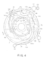
Fig. 4 is a plan view of the disks for explaining the movement of coins in the coin sorting apparatus shown inFig. 1 ; -
Fig. 5 is a sectional view taken on line X-X inFig. 4 , in states where (a) a normal coin, (b) overlapping coins and (c) a deformed coin are moving in the coin passage, respectively; -
Fig. 6 is an enlarged sectional view of a large-coin passage section corresponding to a part ofFig. 5 (c) ; -
Fig. 7 is a sectional view taken on line Y-Y inFig. 4 , in a state where a normal coin is moving in the coin passage; -
Fig. 8 is a sectional view taken on line Z-Z inFig. 4 , in a state where a deformed coin is moving in the coin passage; -
Fig. 9 is an enlarged view of a part ofFig. 4 corresponding to a section including a small-coin sorting guide; -
Fig. 10 is a sectional view taken on line P-P inFig. 9 ; -
Fig. 11 is a view similar toFig. 4 , showing a state where the rotary disk is reversely rotated; -
Fig. 12A is a sectional view showing a modification of the large-coin passage shown inFig. 6 ; -
Fig. 12B is a sectional view showing another modification of the large-coin passage shown inFig. 6 ; -
Fig. 13 is a longitudinal sectional view of a coin sorting apparatus of a related art; -
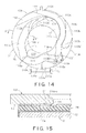
Fig. 14 is a bottom view of a stationary disk of the coin sorting apparatus shown inFig. 13 ; -
Fig. 15 is a sectional view of disks of the coin sorting apparatus shown inFig. 13 , corresponding to a section taken on line X'-X' inFig. 14 , in a state where a deformed coin is moving in the coin passage. - Preferred embodiments of the present invention will be described with reference to
Figs. 1 to 11 of the accompanying drawings. - Referring to
Figs. 1 and 2 , a coin sorting apparatus of the preferred embodiment comprises a stationary disk (stationary member) 1 and arotary disk 2 disposed under thestationary disk 1 contiguously with a lower surface thereof. Thestationary disk 1 and therotary disk 2 are joined by a hinge a1 (Fig. 1 ) so that thestationary disk 1 can be turned on the hinge a1 relative to therotary disk 2. A locking device a2 (Fig. 1 ) connected to a part diametrically opposite to the hinge a1 of thestationary disk 1 locks thestationary disk 1 in place over therotary disk 2. - An inlet opening (coin-feed opening) 1a is formed in a central part of the
stationary disk 1. The coin sorting apparatus is formed such that a coin fed through the inlet opening 1a of thestationary disk 1 slides along thelower surface 1b (Fig. 2 ) of thestationary disk 1 as therotary disk 2 rotates. A guide structure (described later) is formed in thestationary disk 1 for selectively guiding coins sliding along thelower surface 1b of thestationary disk 1, according to the diameters of the coins. - The
rotary disk 2 comprises adisk body 22 supported for rotation on ashaft 20, a disk-shapedresilient member 24 attached to an upper surface of thedisk body 22. As shown inFig. 5 , theresilient member 24 has a thinurethane rubber layer 24a and a porousresilient layer 24b underlying theurethane rubber layer 24a. Preferably, the porousresilient layer 24b is formed of rubber sponge (foam rubber) having a comparatively high impact resilience. Acircular metal plate 23 is attached to the lower surface of theresilient member 24. Themetal plate 23 is fastened to thedisk body 22 withscrews 29 to attach theresilient member 24 detachably to thedisk body 22. - The
resilient member 24 attached to thedisk body 22 holds coins together with thestationary disk 1 and moves the coins as therotary disk 2 rotates. In addition, theresilient member 24 absorbs the variation of the thickness of the gap between theresilient member 24 and thestationary disk 1, and differences in thickness between coins of different denominations (Figs. 5 ,7 and 8 ). - As shown in
Fig. 1 , therotary disk 2 is driven for rotation by amotor 25 through apulley 26 attached to the output shaft of themotor 25 and adrive belt 28 extended between thepulley 26 and the disk body 22 (Fig. 5 )of therotary disk 2. Aconical member 27 is disposed on a central part of therotary disk 2 to prevent coins from staying on the central part of therotary disk 2. - The specific construction of the
stationary disk 1, especially the guide structure formed on thelower surface 1b thereof, will be described with reference toFigs. 3 to 11 . In the following descriptions, reference symbols C1, C2 and C3 denote normal (flat) coins. On the other hand, reference symbols C1', C2' and C3' denote deformed coins bent such that a convex side thereof faces thelower surface 1b of thestationary disk 1, especially the deformed coins fed into a coin passage 10 (described later) with bending axes A (Fig. 6 ) thereof in a substantially tangential direction with respect to thecoin passage 10 as shown inFig. 6 . The bending axis A of each deformed coin C1', C2'or C3' extends in the substantially diametral direction thereof. - As shown in
Fig. 3 , the guide structure comprises acoin passage 10 formed concavely in thelower surface 1b of thestationary disk 1. Thecoin passage 10 extends counterclockwise as viewed inFig. 3 in a meandering spiral from the inlet opening 1a toward the periphery of thestationary disk 1. Thecoin passage 10 has, arranged from the inlet opening 1a toward the periphery of thestationary disk 1, a large-coin passage section 10a, a medium-coin passage section 10b and a small-coin passage section 10c. The large-coin passage section 10a is configured to permit the passage of large, medium and small coins C1, C2 and C3. The medium-coin passage section 10b has a width L1 that permits the passage of only medium and small coins C2 and C3. The small-coin passage section 10c has a width L2 that permits the passage of only small coins C3 in an upstream section thereof. - The large-
coin passage section 10a has acoin entrance 11 facing theinlet opening 1a, andstairs coin entrance 11. Thecoin entrance 11 is formed such that the thickness of a gap between thecoin entrance 11 and theresilient member 24 of the rotary disk 2 (Fig. 2 ) is greater than that of the thickest coins. Thus, all the coins fed into theinlet opening 1a can be moved into thecoin entrance 11 by centrifugal force as therotary disk 2 rotates. - There is a possibility that a pair of overlapping coins are moved into the
coin entrance 11. The overlapping coins include an "upper coin" that is contiguous with thestationary disk 1 and a "lower coin" that is contiguous with the rotary disk 2 (seeFig. 5 (b) ). Thus, thecoin entrance 11 is provided with asemicircular protrusion 100 in a radial outer side thereof. Theprotrusion 100 pushes the "upper coin" back toward theinlet opening 1a. - The
stairs resilient member 24 of the rotary disk 2 (Fig. 2 ) and the large-coin passage section 10a stepwise toward the downstream side thereof. By virtue of thestairs coin passage 10.Fig. 5 (a) shows the state where large coins C1 are moving in a single file in the large-coin passage section 10a. - As shown in
Fig. 3 , acoin returning part 13 is formed contiguously with theinlet opening 1a in a region corresponding to the boundary between the large-coin passage section 10a and the medium-coin passage section 10b. Thecoin returning part 13 deals with overlapping coins passedstairs coin returning part 13 are limited by ansloped step portion 13a and a verticalguiding step portion 13b, respectively. - Since the large-
coin passage section 10a extends spirally away from the center toward the circumference of thestationary disk 1, it is intended that the outer edges of all the coins moving therein should engage a radialinner edge portion 10i-a thereof (seeFig. 4 ). The radialinner edge portion 10i-a defines a shoulder formed in a height smaller than a thickness of a thinnest coin so as not to prevent the "lower coin" from returning toward theinlet opening 1a (seeFig. 5 ). Thecoin returning part 13 is configured to receive the "lower coin" passing over theedge portion 10i-a through thestep portion 13a and return the same coin toward theinlet opening 1a by means of the guidingstep portion 13b. - As shown in
Figs. 3 ,5 and6 , the large-coin passage section 10a has, at least in a section corresponding to theinner edge portion 10i-a, a recessed-profile configured to accommodate the convex sides of the deformed coins C1', C2'and C3' to ensure an engagement of the outer edges of the deformed coins with theedge portion 10i-a.Fig. 6 shows that the large-coin passage section 10a is recessed more deeply than an imaginary reference plane D for the normal coins so as to have the recessed-profile. - The recessed-profile of the large-
coin passage section 10a includes a stepped-profile configured to prop the peripheral part of each of the coins to be guided, on a radial outer side of thepassage section 10a. The stepped-profile of thepassage section 10a includes an outercircumferential step 30 for the large coins and an outercircumferential step 32 for the medium and small coins to form two-stepped-profile corresponding to two ranges of the diameters of the coins. Steppedportions 31 and 33 (Fig. 3 ) are formed at an upstream end and a downstream end of the outercircumferential step 30, respectively. The steppedportions - Referring to
Figs. 3 and4 , a large-coin sorting guide 15a is disposed radially outside the medium-coin passage section 10b to guide only the large coins C1 selectively and to eject the large coins C1 in a substantially tangential direction. The large-coin sorting guide 15a has astep 16a and anejecting passage 17a. Thestep 16a is formed at a boundary between the large-coin passage section 10a and the medium-coin passage section 10b. Thestep 16a is formed such that only a peripheral part of each of the large coins C1 (including the deformed coins C1') of diameters greater than the width L1 of the medium-coin passage section 10b, runs onto thestep 16a (seeFigs. 4 and7 ). - The ejecting
passage 17a has aguide edge 18a for guiding a coin that has run onto thestep 16a for movement in a substantially tangential direction, and anoutlet 19a through which the coin guided by theguide edge 18a is ejected outside. The sortingguide 15a further has a steppedportion 18a' formed transversely of a coin-passing direction between thestep 16a and theejecting passage 17a. The steppedportion 18a' has a sloped configuration for allowing the coins to pass easily. - Since all the coins engage the radial
inner edge portion 10i-a, the medium coins C2 and the small coins C3 respectively having diameters smaller than the width L1 do not run onto thestep 16a and move into the medium-coin passage section 10b. - On the other hand, an outer edge of each of the medium and small deformed coins C2'and C3' is difficult to engage a radial outer edge 10o of the
coin passage 10 between thestep 16a and theejecting passage 17a. Accordingly, there is a strong possibility that the deformed coins C2' and C3' pass over the edge 10o to enter theejecting passage 17a. Thus, almost all the deformed coins C2'and C3' are ejected outside from theoutlet 19a of theejecting passage 17a, in the same way as the large deformed coin C1'. - A medium-
coin sorting guide 15b is disposed radially outside the small-coin passage section 10c to guide only the medium coins C2 selectively and to eject the medium coins C2 in a substantially tangential direction. The medium-coin sorting guide 15b, similarly to the large-coin sorting guide 15a, has astep 16b and anejecting passage 17b. - The
step 16b is formed at a boundary between the medium-coin passage section 10b and the small-coin passage section 10c. Thestep 16b is formed such that only a peripheral part of each of the medium coins C2 of diameters greater than the width L2 of the small-coin passage section 10c runs onto thestep 16b. Aramp 16b' (Fig. 3 ) is formed on the upstream side of thestep 16b to facilitate coins running onto thestep 16b. - The ejecting
passage 17b, similarly to theejecting passage 17a of the large-coin sorting guide 15a, has aguide edge 18b and anoutlet 19b. The sortingguide 15b further has a steppedportion 18a' formed transversely of a coin-passing direction between thestep 16b and theejecting passage 17b. The steppedportion 18b' also has a sloped configuration for allowing the coins to pass easily. - Since a downstream part of the medium-
coin passage section 10b extends away from the center toward the outer circumference of thestationary disk 1, it is intended that the outer edges of all the coins moving therein should engage a radialinner edge portion 10i-b thereof (seeFig. 4 ). Thus, small coins C3 of a diameter smaller than the width L2 move into the small-coin passage section 10c without running onto thestep 16b. - The small-
coin passage section 10c extends downstream toward the inner circumference and then toward the outer circumference of thestationary disk 1, and terminates in a small-coin sorting guide 15c having anoutlet 19c. The small-coin sorting guide 15c is configured to guide only the small coins C3 selectively and to eject the small coins C3 in a substantially tangential direction. Since a downstream part of the small-coin passage section 10c also extends away from the center toward the outer circumference of thestationary disk 1, it is intended that the outer edges of all the coins moving therein should engage a radialinner edge portion 10i-c thereof (seeFig. 4 ). The radialinner edge portion 10i-c also defines a shoulder formed in a height smaller than the thickness of the thinnest coin so as not to prevent the "lower coin" from returning toward theinlet opening 1a (coin entrance 11). - As described above, almost all the deformed coins C2' and C3' are ejected outside from the
outlet 19a for the large coins. There is a possibility that some of the deformed coins C2'and C3' pass though the medium-coin passage section 10b and enter the small-coin passage section 10c. - Thus, as shown in
Figs. 3 and8 , the small-coin passage section 10c also has, at least in a section corresponding to theinner edge portion 10i-c, a recessed-profile configured to accommodate the convex sides of the deformed coins C2'and C3' to ensure an engagement of the outer edges of the deformed coins with theedge portion 10i-c. The recessed-profile of the small-coin passage section 10c includes a stepped-profile configured to prop the peripheral part of each of the coins to be guided, on a radial outer side of thepassage section 10c. The stepped-profile of thepassage section 10c includes an outercircumferential step 34 for the medium and small coins. Steppedportions 35 and 36 (Fig. 3 ) are formed at an upstream end and a downstream end of the outercircumferential step 34, respectively. The steppedportions - Referring to
Figs. 3 ,9 and 10 , in a downstream part of the small-coin passage section 10c, aprotrusion 40 is formed on a radial outer side thereof before theoutlet 19c. Theprotrusion 40 has abevel 41 for returning the medium coins. Aslope portion 42 is formed in an opposite side of the small-coin passage section 10c to thebevel 41 of theprotrusion 40. - Even if the medium coin C2 (including the deformed medium coin C2') enters the small-
coin passage section 10c for some reason, it is possible to return the medium coin C2 toward theinlet opening 1a (coin entrance 11) by means of thebevel 41 of theprotrusion 40 and theslope portion 42. That is to say, the medium coin C2 is pushed by thebevel 41 toward the radial inner side of thepassage section 10c so that the medium coin C2 runs onto theslope portion 42. Then, the medium coin C2 is returned toward theinlet opening 1a while passing over the radial inner side of thepassage section 10c, as therotary disk 2 rotates forward, i.e. in normal direction. - Referring to
Figs. 3 and11 , in a upstream part of the large-coin passage section 10a (whenrotary disk 2 rotates forward), a return guide 5 having areturn passage 50 and a guidingedge 52 is formed on a radial outer side thereof. The return guide 5 is configured to guide the coins that have moved to the radial outer side of thestationary disk 1 to return the same coins toward theinlet opening 1a (coin entrance 11) when therotary disk 2 is rotated in the reverse direction, as shown inFig. 11 . A steppedportion 51 is formed at an entrance ofreturn passage 50, i.e. an upstream end of thereturn passage 50 when therotary disk 2 is reversely rotated. The steppedportion 51 has a sloped configuration for allowing the coins to pass easily. - As shown in
Fig. 3 , thecoin passage 10 extends downstream from thesteps stationary disk 1, respectively. That is to say, two sections of thecoin passage 10 downstream from thesteps inner edge portions 10i-a' and 10i-b' approaching the center of thestationary disk 1, respectively. Therefore, when therotary disk 2 is reversely rotated, theinner edge portions 10i-a' and 10i-b' urge coins radial outward to ensure the engagement of the coins with theedge portions 10i-a' and 10i-b'. Thus, even if the return guide 5 fails to return some coins toward theinlet opening 1a when therotary disk 2 is reversely rotated, it is intended that the outer edges of those coins should engage theinner edge portions 10i-a and 10i-b opposite thesteps rotary disk 2 is rotated forward again. - As sown in
Fig. 3 , in this preferred embodiment, thesteps stationary disk 1 with screws. The step plates S1 and S2 may be horizontally adjustable on thestationary disk 1 with respect to the width of thecoin passage 10. In this case, the widths L1 and L2 of thecoin passage 10 corresponding to thesteps coin passage 10. The step plates S1 and S2 may be formed of an abrasion-resistant material separately from thestationary disk 1 and may be subjected to a hardening process. - The functions and effects of this embodiment thus constructed will be described. Some of the functions and effects will be omitted or simplified, if those functions and effects are apparent from the foregoing descriptions.
- According to this embodiment, it is possible to ensure the engagement of the outer edge of the deformed coins C1', C2' and C3' with the radial
inner edge portions 10i-a and 10i-c of thepassage sections - In addition, the stepped-profile of the
passage section 10a includes two outercircumferential steps passage section 10a having an optimum configuration for each of the ranges of the diameters of the coins. - In this embodiment, almost all the deformed coins C1', C2' and C3' are ejected outside from the
outlet 19a for large coins. Thus, it is possible to sort the deformed coins C1', C2' and C3' from the medium and small normal coins C2 and C3. Accordingly, it is advantageous that the large coins C1 are treated as reject coins, because the deformed coins C1', C2' and C3' can be treated as the reject coins together with the large coins C1. - By the way, there is a possibility that few medium and small deformed coins C2' and C3' are sorted out together with the medium and small normal coins C2and C3, respectively. There is also a possibility that the medium and small deformed coins C2'and C3' happen to be fed into the
coin passage 10 with their bending axes in substantially radial direction with respect to thecoin passage 10. In addition, there may be some medium and small coins bent such that convex sides thereof face the upper surface of therotary disk 2, as opposed to the deformed coins C2' and C3'. There is a strong possibility that those medium and small coins are sorted out together with the medium and small normal coins C2and C3, respectively. Thus, those coins may be separately rejected by using an optical discriminator and so forth, after they are sorted by the sorting apparatus of this embodiment, e.g. before the sorted coins are re-sorted by denominations. - The stepped
portions 18a' and 18b' (Fig. 3 ) between thesteps passages passages portions 18a' and 18b' to smoothly return to the opposite side from the ejectingpassages rotary disk 2 is reversely rotated. In thepassage sections portions 33 and 36 (Fig. 3 ) of the outercircumferential steps rotary disk 2 is rotated forward again. In addition, it is possible to ensure a reliability of a batch stopping operation, i.e. an operation in which the coin sorting operation is suspended and resumed by stopping therotary disk 2 and rotating therotary disk 2 forward as occasion demands. - Furthermore, when the
rotary disk 2 is reversely rotated, it is possible to reduce coins that are held-up between thestationary disk 1 and therotary disk 2 by means of the return guide 5. Accordingly, it is possible to more smoothly resume the normal coin sorting operation when therotary disk 2 is rotated forward again. - Some modifications of this embodiment will be described. In the present invention, the recessed-profile of the coin passage is not limited to that described above. The recessed-profile may be any kind of profile configured to accommodate the convex side of the deformed coin to ensure the engagement of the outer edge of the deformed coin with the radial inner edge portions.
- For example, in place of the recessed-profile of the large-
coin passage section 10a shown inFig. 6 , modified recessed-profiles are shown inFigs. 12A and 12B . In thepassage section 10a shown inFig. 6 , the imaginary reference plane D for the normal coins inclines downwardly from the radial inner side toward the outer side of thepassage section 10a (the example of the reference plane D for the large normal coin C1 is shown inFig. 6 ). On the other hand,Fig. 12A shows apassage section 10a' in which the reference plane D inclines oppositely, i.e. upwardly from the radial inner side toward the outer side thereof.Fig. 12B shows apassage section 10a" in which the reference plane D is substantially horizontal. Incidentally, for clearer comparison of the profiles, each of thepassage sections 10a' and 10a" (Figs. 12A and 12B ) has a more simple recessed-profile than the stepped-profile shown inFig. 6 . That is to say, each of the recessed-profiles of thepassage sections 10a' and 10a" is the simple profile merely corresponding to the convex side of the deformed coin C1'.
Claims (3)
- A coin sorting apparatus comprising:(a) a stationary member (1) provided with a central coin-feed opening (1a); and(b) a rotary disk (2) supported for rotation and disposed under the stationary member (1) contiguously with a lower surface (1b) of the stationary member (1),the coin sorting apparatus being constructed such that coins (C1,C2,C3) fed into the coin-feed opening (1a) of the stationary member (1) slide along the lower surface (1b) of the stationary member (1) as the rotary disk (2) rotates,
and the coin sorting apparatus being adapted to receive coins including a deformed coin (C1',C2',C3') bent such that a convex side thereof faces the lower surface (lb) of the stationary member (l),
the stationary member (1) being provided with a guide structure for selectively guiding coins (C1,C2,C3) sliding along the lower surface (1b) thereof, according to the diameters of the coins (C1,C2,C3),
the guide structure having
a coin passage (10) formed in the lower surface (1b) of the stationary member (1),
characterised by the coin passage (10) having an edge portion (10i-a) configured to engage outer edges of all the coins to be guided, the edge portion (10i-a) defining a shoulder formed in a height smaller than a thickness of a thinnest coin (3), and
a coin-sorting guide (15) disposed radially outside the coin passage (10),
the coin-sorting guide having
an ejecting passage (17a) for guiding a to-be-selected coin (C1) whose outer edge has been engaged by the edge portion (10i-a) of the coin passage (10) and ejecting the same coin (C1) outside the stationary member (1),
the coin passage (10) having, at least in a section corresponding to the edge portion (10i-a) thereof, a recessed-profile configured to accommodate the convex side of the deformed coin (C1',C2',C3') to ensure an engagement of an outer edge of the deformed coin (C1',C2',C3') with the edge portion (10i-a). - The coin sorting apparatus according to claim 1, wherein the recessed-profile of the coin passage (10) includes a stepped-profile (30,32) configured to prop the peripheral part of each of the coins (C1,C2,C3) to be guided, on the opposite side of the coin passage (10) to the edge portion (10i-a).
- The coin sorting apparatus according to claim 2, wherein the recessed-profile (30,32) of the coin passage (10) includes a plurality of stepped-profiles (30,32) corresponding to a plurality of ranges of the diameters of the coins (C1,C2,C3).
Applications Claiming Priority (2)
| Application Number | Priority Date | Filing Date | Title |
|---|---|---|---|
| JP2001397502A JP3989724B2 (en) | 2001-12-27 | 2001-12-27 | Coin sorting machine |
| EP02258828A EP1324277B1 (en) | 2001-12-27 | 2002-12-23 | Coin sorting apparatus |
Related Parent Applications (1)
| Application Number | Title | Priority Date | Filing Date |
|---|---|---|---|
| EP02258828A Division EP1324277B1 (en) | 2001-12-27 | 2002-12-23 | Coin sorting apparatus |
Publications (2)
| Publication Number | Publication Date |
|---|---|
| EP2124200A2 true EP2124200A2 (en) | 2009-11-25 |
| EP2124200A3 EP2124200A3 (en) | 2010-01-13 |
Family
ID=19189205
Family Applications (2)
| Application Number | Title | Priority Date | Filing Date |
|---|---|---|---|
| EP09168097A Withdrawn EP2124200A3 (en) | 2001-12-27 | 2002-12-23 | Coin sorting apparatus |
| EP02258828A Expired - Lifetime EP1324277B1 (en) | 2001-12-27 | 2002-12-23 | Coin sorting apparatus |
Family Applications After (1)
| Application Number | Title | Priority Date | Filing Date |
|---|---|---|---|
| EP02258828A Expired - Lifetime EP1324277B1 (en) | 2001-12-27 | 2002-12-23 | Coin sorting apparatus |
Country Status (5)
| Country | Link |
|---|---|
| US (1) | US6945864B2 (en) |
| EP (2) | EP2124200A3 (en) |
| JP (1) | JP3989724B2 (en) |
| AT (1) | ATE444542T1 (en) |
| DE (1) | DE60233857D1 (en) |
Families Citing this family (8)
| Publication number | Priority date | Publication date | Assignee | Title |
|---|---|---|---|---|
| JP4320673B2 (en) * | 2006-12-08 | 2009-08-26 | ソニー株式会社 | Information processing apparatus and method, and program |
| US8475242B2 (en) * | 2010-08-13 | 2013-07-02 | Gregory F. String | Coin sorting plate with recessed coin slots |
| ES2569863T3 (en) * | 2012-10-15 | 2016-05-12 | Wincor Nixdorf International Gmbh | Device for separating coins with a rotating drive disc |
| CN105809808A (en) * | 2016-03-17 | 2016-07-27 | 成都大学 | Mechanical coin classifier |
| US10181234B2 (en) | 2016-10-18 | 2019-01-15 | Cummins-Allison Corp. | Coin sorting head and coin processing system using the same |
| US10679449B2 (en) | 2016-10-18 | 2020-06-09 | Cummins-Allison Corp. | Coin sorting head and coin processing system using the same |
| GB2613488B (en) * | 2019-01-04 | 2023-08-23 | Cummins Allison Corp | Coin pad for coin processing system |
| US11847879B2 (en) | 2020-07-31 | 2023-12-19 | Cummins-Allison Corp. | Coin sorting disc with coin flow management features |
Citations (1)
| Publication number | Priority date | Publication date | Assignee | Title |
|---|---|---|---|---|
| JP2001079206A (en) | 2000-08-30 | 2001-03-27 | Sankyo Kk | Game machine |
Family Cites Families (7)
| Publication number | Priority date | Publication date | Assignee | Title |
|---|---|---|---|---|
| US4474197A (en) * | 1981-11-30 | 1984-10-02 | Glory Kogyo Kabushiki Kaisha | Coin transfer apparatus |
| US5022889A (en) * | 1986-06-23 | 1991-06-11 | Ristvedt Victor G | Coin sorter |
| US5299977A (en) * | 1990-05-14 | 1994-04-05 | Cummins-Allison Corp. | Coin handling system |
| US5372542A (en) * | 1993-07-09 | 1994-12-13 | Cummins-Allison Corp. | Disc coin sorter with improved exit channel |
| GB9515567D0 (en) * | 1995-07-28 | 1995-09-27 | Coin Control Limited | Coin control mechanism |
| US5782686A (en) * | 1995-12-04 | 1998-07-21 | Cummins-Allison Corp. | Disc coin sorter with slotted exit channels |
| US6609604B1 (en) * | 1998-03-18 | 2003-08-26 | Cummins-Allison Corp. | Coin processing system for discriminating and counting coins from multiple countries |
-
2001
- 2001-12-27 JP JP2001397502A patent/JP3989724B2/en not_active Expired - Fee Related
-
2002
- 2002-12-23 EP EP09168097A patent/EP2124200A3/en not_active Withdrawn
- 2002-12-23 AT AT02258828T patent/ATE444542T1/en not_active IP Right Cessation
- 2002-12-23 EP EP02258828A patent/EP1324277B1/en not_active Expired - Lifetime
- 2002-12-23 DE DE60233857T patent/DE60233857D1/en not_active Expired - Lifetime
- 2002-12-27 US US10/329,400 patent/US6945864B2/en not_active Expired - Fee Related
Patent Citations (1)
| Publication number | Priority date | Publication date | Assignee | Title |
|---|---|---|---|---|
| JP2001079206A (en) | 2000-08-30 | 2001-03-27 | Sankyo Kk | Game machine |
Also Published As
| Publication number | Publication date |
|---|---|
| EP1324277A3 (en) | 2004-05-26 |
| ATE444542T1 (en) | 2009-10-15 |
| EP1324277A2 (en) | 2003-07-02 |
| US6945864B2 (en) | 2005-09-20 |
| EP1324277B1 (en) | 2009-09-30 |
| US20030124966A1 (en) | 2003-07-03 |
| JP2003196697A (en) | 2003-07-11 |
| DE60233857D1 (en) | 2009-11-12 |
| JP3989724B2 (en) | 2007-10-10 |
| EP2124200A3 (en) | 2010-01-13 |
Similar Documents
| Publication | Publication Date | Title |
|---|---|---|
| US4775354A (en) | Coin sorting apparatus with rotating disc stationary guide plate for sorting coins by their different diameters | |
| JP2757970B2 (en) | Coin sorting device with a wall between exit passages | |
| EP0691015B1 (en) | Coin queuing device and power rail sorter | |
| US5542881A (en) | Coin sorting mechanism having dual recycle channels | |
| CA1335192C (en) | Coin sorting mechanism | |
| US5489237A (en) | Coin queuing and sorting arrangement | |
| JP3367103B2 (en) | Coin handling device having two disks | |
| AU676354B2 (en) | Disc coin sorter with improved exit channel | |
| EP0602045B1 (en) | Disc-type coin sorter with multiple-path queuing | |
| US5468182A (en) | Disc-type coin sorter with adjustable targeting inserts | |
| JPH0327490A (en) | Coin sorter | |
| US5782686A (en) | Disc coin sorter with slotted exit channels | |
| WO1987002492A1 (en) | Spiral coin-queueing head for high-speed coin-sorting and counting apparatus | |
| WO1993000660A1 (en) | Disc-type coin sorter with movable bearing surface | |
| US10964148B2 (en) | Coin sorting system coin chute | |
| CN103971442B (en) | Coin discharger | |
| EP1324277B1 (en) | Coin sorting apparatus | |
| US12437598B2 (en) | Coin sorting disc with coin flow management features | |
| JP2003187288A (en) | Coin delivery device | |
| JP2002190046A (en) | Coin sorter | |
| JP2002133486A (en) | Coin selector | |
| JPS5894083A (en) | Coin delivery unit | |
| JP2002279471A (en) | Coin-sorting machine | |
| JPH0223910B2 (en) |
Legal Events
| Date | Code | Title | Description |
|---|---|---|---|
| PUAI | Public reference made under article 153(3) epc to a published international application that has entered the european phase |
Free format text: ORIGINAL CODE: 0009012 |
|
| AC | Divisional application: reference to earlier application |
Ref document number: 1324277 Country of ref document: EP Kind code of ref document: P |
|
| AK | Designated contracting states |
Kind code of ref document: A2 Designated state(s): AT BE BG CH CY CZ DE DK EE ES FI FR GB GR IE IT LI LU MC NL PT SE SI SK TR |
|
| PUAL | Search report despatched |
Free format text: ORIGINAL CODE: 0009013 |
|
| AK | Designated contracting states |
Kind code of ref document: A3 Designated state(s): AT BE BG CH CY CZ DE DK EE ES FI FR GB GR IE IT LI LU MC NL PT SE SI SK TR |
|
| 17P | Request for examination filed |
Effective date: 20100709 |
|
| 17Q | First examination report despatched |
Effective date: 20100903 |
|
| STAA | Information on the status of an ep patent application or granted ep patent |
Free format text: STATUS: THE APPLICATION IS DEEMED TO BE WITHDRAWN |
|
| 18D | Application deemed to be withdrawn |
Effective date: 20160701 |