EP2123977A1 - Tube support plate of steam generator - Google Patents
Tube support plate of steam generator Download PDFInfo
- Publication number
- EP2123977A1 EP2123977A1 EP08704001A EP08704001A EP2123977A1 EP 2123977 A1 EP2123977 A1 EP 2123977A1 EP 08704001 A EP08704001 A EP 08704001A EP 08704001 A EP08704001 A EP 08704001A EP 2123977 A1 EP2123977 A1 EP 2123977A1
- Authority
- EP
- European Patent Office
- Prior art keywords
- holes
- support plate
- tube support
- hole
- tube
- Prior art date
- Legal status (The legal status is an assumption and is not a legal conclusion. Google has not performed a legal analysis and makes no representation as to the accuracy of the status listed.)
- Granted
Links
Images




Classifications
-
- F—MECHANICAL ENGINEERING; LIGHTING; HEATING; WEAPONS; BLASTING
- F22—STEAM GENERATION
- F22B—METHODS OF STEAM GENERATION; STEAM BOILERS
- F22B37/00—Component parts or details of steam boilers
- F22B37/02—Component parts or details of steam boilers applicable to more than one kind or type of steam boiler
- F22B37/10—Water tubes; Accessories therefor
- F22B37/20—Supporting arrangements, e.g. for securing water-tube sets
- F22B37/205—Supporting and spacing arrangements for tubes of a tube bundle
-
- G—PHYSICS
- G21—NUCLEAR PHYSICS; NUCLEAR ENGINEERING
- G21D—NUCLEAR POWER PLANT
- G21D1/00—Details of nuclear power plant
-
- Y—GENERAL TAGGING OF NEW TECHNOLOGICAL DEVELOPMENTS; GENERAL TAGGING OF CROSS-SECTIONAL TECHNOLOGIES SPANNING OVER SEVERAL SECTIONS OF THE IPC; TECHNICAL SUBJECTS COVERED BY FORMER USPC CROSS-REFERENCE ART COLLECTIONS [XRACs] AND DIGESTS
- Y02—TECHNOLOGIES OR APPLICATIONS FOR MITIGATION OR ADAPTATION AGAINST CLIMATE CHANGE
- Y02E—REDUCTION OF GREENHOUSE GAS [GHG] EMISSIONS, RELATED TO ENERGY GENERATION, TRANSMISSION OR DISTRIBUTION
- Y02E30/00—Energy generation of nuclear origin
Definitions
- This invention relates to a tube support plate of a steam generator, which is designed to be capable of decreasing a pressure loss and ensuring sufficient strength.
- a pressurized water nuclear power plant primary cooling water heated in a nuclear reactor (reactor) is supplied to a steam generator.
- secondary cooling water is heated by the heat of the primary cooling water to generate secondary steam.
- This secondary steam is supplied to a steam turbine to rotate the steam turbine, thereby driving an electric generator.
- a tube plate 12 is integrally connected to a lower portion of a vertical outer tube 11 of the steam generator 10.
- a main steam pipe 13 and a feed water pipe 14 are connected to an upper portion of the outer tube 11.
- the tube plate 12 is a plate-shaped member with a large wall thickness, and is disposed in such a state as to close the lower portion of the outer tube 11. Many holes are formed in the tube plate 12.
- the space below the tube plate 12 is separated into a high temperature side water chamber 16 and a low temperature side water chamber 17 by a partition plate 15.
- An inner tube 18 is disposed within the outer tube 11.
- a multiplicity of inverted U-shaped heat transfer tubes 19 are arranged within the inner tube 18. Although schematically shown in the drawing, the number of the heat transfer tubes 19 arranged is very large. These heat transfer tubes 19 are arranged in a vertically extending state, and the upper end of each heat transfer tube 19 is curved in an inverted U shape. Both ends, on the lower side, of each heat transfer tube 19 are inserted into many holes formed in the tube plate 12, fixed by being enlarged, and connected to the high temperature side water chamber 16 and the low temperature side water chamber 17, respectively.
- tube support plates 20 extending in a horizontal direction are arranged at a plurality of locations along the height direction of the inner tube 18. Through-holes, through which the many heat transfer tubes 19 pass, are formed in the tube support plate 20.
- the tube support plate 20 is used to prevent vibration of the heat transfer tube 19 and maintain spacing between the heat transfer tubes 19. That is, since the many heat transfer tubes 19 pass through the tube support plates 20, the spacing between the heat transfer tubes 19 can be maintained, and the vibration of the heat transfer tubes 19 can be prevented.
- a lateral load acts, for example, in an earthquake, this lateral load is supported by the tube support plates 20.
- a steam separator 21 and a steam dryer 22 are disposed in an upper portion of the outer tube 11.
- Primary cooling water W1 heated in a reactor is supplied to the high temperature side water chamber 16, flowed in the heat transfer tubes 19, passed through the low temperature side water chamber 17, and returned to the reactor.
- secondary cooling water W2 is supplied through the feed water pipe 14 into a space between the outer tube 11 and the inner tube 18 (the space is a downcomer), and then flowed downward within the downcomer.
- the secondary cooling water W2 enters the interior of the inner tube 18 from the lower end of the inner tube 18, and ascends within the inner tube 18. While ascending and flowing within the inner tube 18, the secondary cooling water W2 receives heat from the primary cooling water W1 via the heat transfer tubes 19 to undergo heating.
- steam S is produced, and this steam S passes through the steam separator 21, the steam dryer 22, and the main steampipe 13 for feeding to a steam turbine.
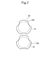
- Fig. 6 is a plan view of the tube support plate 20 viewed from above. Many (for example, several thousand) through-holes 20a are formed in a central portion of the tube support plate 20 (in the drawing, the central portion is a crosshatched portion). So far, the shape of the through-hole 20a has been a three-leaved shape (the shape of clover), as shown in Fig. 7 . In Fig. 7 , only two of the through-holes 20a are shown, but actually, the tube support plate 20 is laid with the through-holes 20a of such a three-leaved shape arranged longitudinally and transversely in a lattice pattern.
- the through-hole 20a performs the function of supporting the heat transfer tube 19, and the function of a flow path for flowing the secondary cooling water W and steam S ascending and passing within the inner tube 18.
- Patent Document 1 Japanese Unexamined Patent Publication No. 1991-255892
- the lateral load is imposed on the tube support plate 20 as well. If, on this occasion, the in-plane compressive strength of the tube support plate 20 is low, the through-hole 20a may collapse and its edge may touch the heat transfer tube 19, thereby deforming (damaging) the heat transfer tube 19. To prevent the occurrence of such an event, the tube support plate 2 0 needs to have a certain in-plane strength.
- the present invention has been accomplished in the light of the above-described prior art. It is an object of the invention to provide a tube support plate of a steam generator involving a small pressure loss and having sufficient strength. Means for Solving the Problems
- the present invention configured to solve the above problems, is a tube support plate of a steam generator, which is disposed within the steam generator and has many through-holes formed therein for passage of heat transfer tubes, characterized in that a hole shape of the through-hole is a hexagonal shape, and every other side of sides forming the hexagonal shape has a protrusion formed therein, the protrusion protruding toward a center of the through-hole, and an arrangement of the through-holes is such that many horizontal rows of the through-holes are arranged in parallel, each horizontal row including the through-holes arranged in a straight line with a constant pitch, and that positions of the through-holes arranged in each horizontal row of the through-holes are shifted by a half of the pitch from corresponding positions of the through-holes arranged in the adjacent horizontal row of the through-holes.
- the tube support plate is also characterized in that end portions of the sides are curved.
- the hole shape of the through-hole is a hexagonal shape, and the arrangement of the through-holes is a so-called honeycomb arrangement.
- the area of the through-hole can be increased to decrease the pressure loss, compared with the prior art, and the in-plane strength can be rendered equal to that of the prior art.
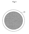
- Fig. 1 is a plan view of a tube support plate 200 according to the embodiment, which is viewed from above. Many (for example, several thousand) through-holes 100 are formed in a central portion of the tube support plate 200 (in Fig. 1 , the central portion is a crosshatched portion).
- the tube support plate 200 is disposed in a horizontal state within a steam generator having the same structure as that shown in Fig. 5 .
- Heat transfer tubes 210 pass through the through-holes 100 in a vertical direction.
- the numeral "100" is used to show the through-hole in a generic manner. When the respective through-holes are shown in a distinguished manner, numerical values in the hundreds, such as the numerals "110, 120, !, are used for explanation.
- the shape of the through-hole 100 is a hexagonal shape, as shown in Fig. 2 . That is, the hole shape of the through-hole 100 is a hexagonal shape surrounded by six sides, 101, 102, 103, 104, 105 and 106. In addition, opposite end portions of the respective sides, 101, 102, 103, 104, 105 and 106, are curved, and portions of the adjacent sides connected together are in a curved shape (a curved shape convex toward the outer periphery as viewed from the center of the hole).
- the alternate sides 102, 104 and 106 have protrusions 100a, 100b and 100c formed therein which protrude toward the center of the through-hole 100 (namely, toward the heat transfer tube 210).
- the respective protrusions 100a, 100b and 100c are formed in middle portions of the sides 102, 104 and 106, and perform the function of maintaining clearance with respect to the heat transfer tube 210, and the function of supporting the heat transfer tube 210.
- the space between the through-hole 100 and the outer peripheral surface of the heat transfer tube 210 defines a flow path for secondary cooling water and steam.
- through-holes 111, 112, 113, 114, 115 ... are arranged in a straight line with a constant pitch to constitute a longitudinal row 110 of the through-holes
- through-holes 121, 122, 123, 124, 125 ... are arranged in a straight line with a constant pitch to constitute a longitudinal row 120 of the through-holes
- through-holes 131, 132, 133, 134, 135 ... are arranged in a straight line with a constant pitch to constitute a longitudinal row 130 of the through-holes.
- a multiplicity of such longitudinal rows 110, 120, 130 ... of the through-holes are arranged in parallel.
- the positions of the through-holes arranged in each horizontal row of the through-holes are shifted, along the direction of the straight-line arrangement of the through-holes (i.e., ⁇ -direction), by a half of the pitch from the corresponding positions of the through-holes arranged in the adjacent horizontal row of the through-holes.
- the through-holes 111, 112, 113, 114, 115 ... of the longitudinal row 110 of the through-holes and the through-holes 121, 122, 123, 124, 125 ... of the longitudinal row 120 of the through-holes are arranged, shifted by a half of the pitch, with respect to the ⁇ -direction.
- the through-holes 100 are in a honeycomb arrangement (triangular arrangement).
- the triangular arrangement refers, for example, to an arrangement in which the hole centers of the through-holes 111, 112 and 121 are connected by lines to form a triangle.
- the positions of arrangement of the heat transfer tubes 210 are also set.
- the hole shape of the through-hole 100 is a hexagonal shape.
- the area of the hole is so wide that the pressure loss was successfully decreased by about 30% compared with the prior art (the three-leaved shape shown in Fig. 7 ).
- the state of arrangement of the through-holes 100 is the honeycomb arrangement (triangular arrangement).
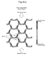
- Fig. 4(a) is a stress distribution view in which compressive load is imposed on the tube support plate having the through-holes of a three-leaved shape (clover shape) shown in Fig. 7 .
- Fig. 4(b) is a stress distribution view in which compressive load is imposed on the tube support plate having the through-holes of a hexagonal shape shown in Fig. 2 .
- Fig. 4(a) shows that with the through-holes of the three-leaved shape (clover shape), flexural deformation occurs in A portions in the drawing.
- Fig. 4(b) shows that with the through-holes of the hexagonal shape, flexural deformation occurs minimally.
- the through-holes of the hexagonal shape increased in the hole area as compared with the through-holes of the three-leaved shape (clover shape), were kept from flexural deformation. As a result, it was confirmed that even when the ligament L shown in Fig. 2 was rendered small, strength comparable to that of the conventional three-leaved type (clover type) was obtained successfully.
- the present invention can be applied not only to a tube support plate employed in a steam generator for use in a nuclear power plant, but also to tube support plates employed in various steam generators having many heat transfer tubes.
Landscapes
- Engineering & Computer Science (AREA)
- Physics & Mathematics (AREA)
- Thermal Sciences (AREA)
- Mechanical Engineering (AREA)
- General Engineering & Computer Science (AREA)
- Heat-Exchange Devices With Radiators And Conduit Assemblies (AREA)
- Hydrogen, Water And Hydrids (AREA)
- Fuel Cell (AREA)
Abstract
Description
- This invention relates to a tube support plate of a steam generator, which is designed to be capable of decreasing a pressure loss and ensuring sufficient strength.
- In a pressurized water nuclear power plant, primary cooling water heated in a nuclear reactor (reactor) is supplied to a steam generator. In the steam generator, secondary cooling water is heated by the heat of the primary cooling water to generate secondary steam. This secondary steam is supplied to a steam turbine to rotate the steam turbine, thereby driving an electric generator.
- The structure of a
steam generator 10 used in a pressurized water nuclear power plant will be explained by reference toFig. 5 . - As shown in
Fig. 5 , atube plate 12 is integrally connected to a lower portion of a verticalouter tube 11 of thesteam generator 10. Amain steam pipe 13 and afeed water pipe 14 are connected to an upper portion of theouter tube 11.
Thetube plate 12 is a plate-shaped member with a large wall thickness, and is disposed in such a state as to close the lower portion of theouter tube 11. Many holes are formed in thetube plate 12. - The space below the
tube plate 12 is separated into a high temperatureside water chamber 16 and a low temperatureside water chamber 17 by apartition plate 15. - An
inner tube 18 is disposed within theouter tube 11. A multiplicity of inverted U-shapedheat transfer tubes 19 are arranged within theinner tube 18. Although schematically shown in the drawing, the number of theheat transfer tubes 19 arranged is very large. Theseheat transfer tubes 19 are arranged in a vertically extending state, and the upper end of eachheat transfer tube 19 is curved in an inverted U shape. Both ends, on the lower side, of eachheat transfer tube 19 are inserted into many holes formed in thetube plate 12, fixed by being enlarged, and connected to the high temperatureside water chamber 16 and the low temperatureside water chamber 17, respectively. - Furthermore,
tube support plates 20 extending in a horizontal direction are arranged at a plurality of locations along the height direction of theinner tube 18. Through-holes, through which the manyheat transfer tubes 19 pass, are formed in thetube support plate 20. Thetube support plate 20 is used to prevent vibration of theheat transfer tube 19 and maintain spacing between theheat transfer tubes 19. That is, since the manyheat transfer tubes 19 pass through thetube support plates 20, the spacing between theheat transfer tubes 19 can be maintained, and the vibration of theheat transfer tubes 19 can be prevented.
Moreover, when a lateral load acts, for example, in an earthquake, this lateral load is supported by thetube support plates 20. - In an upper portion of the
outer tube 11, asteam separator 21 and asteam dryer 22 are disposed. - Primary cooling water W1 heated in a reactor is supplied to the high temperature
side water chamber 16, flowed in theheat transfer tubes 19, passed through the low temperatureside water chamber 17, and returned to the reactor.
On the other hand, secondary cooling water W2 is supplied through thefeed water pipe 14 into a space between theouter tube 11 and the inner tube 18 (the space is a downcomer), and then flowed downward within the downcomer. The secondary cooling water W2 enters the interior of theinner tube 18 from the lower end of theinner tube 18, and ascends within theinner tube 18. While ascending and flowing within theinner tube 18, the secondary cooling water W2 receives heat from the primary cooling water W1 via theheat transfer tubes 19 to undergo heating. Thus, steam S is produced, and this steam S passes through thesteam separator 21, thesteam dryer 22, and themain steampipe 13 for feeding to a steam turbine. - In the above-described manner, with the steam S being generated, the water level H within the downcomer is kept nearly constant.
-
Fig. 6 is a plan view of thetube support plate 20 viewed from above. Many (for example, several thousand) through-holes 20a are formed in a central portion of the tube support plate 20 (in the drawing, the central portion is a crosshatched portion).
So far, the shape of the through-hole 20a has been a three-leaved shape (the shape of clover), as shown inFig. 7 . InFig. 7 , only two of the through-holes 20a are shown, but actually, thetube support plate 20 is laid with the through-holes 20a of such a three-leaved shape arranged longitudinally and transversely in a lattice pattern. - The through-
hole 20a performs the function of supporting theheat transfer tube 19, and the function of a flow path for flowing the secondary cooling water W and steam S ascending and passing within theinner tube 18. - [Patent Document 1] Japanese Unexamined Patent Publication No.
1991-255892 - If a pressure loss, which occurs during passage of the secondary cooling water W2 and steam S through the through-
holes 20a of thetube support plate 20, is great, instability of the water level H in the downcomer portion increases.
If the water level H in the downcomer portion becomes so unstable that the height of the water level oscillates, water reaches thesteam separator 21, lowering the efficiency of thesteam generator 10. - Thus, there is need to decrease the pressure loss at the
tube support plate 20. If the hole area of the through-hole 20a is increased to decrease the pressure loss, however, the strength of thetube support plate 20 lowers. - If the
steam generator 10 is subjected to a heavy lateral load by an earthquake, for example, the lateral load is imposed on thetube support plate 20 as well. If, on this occasion, the in-plane compressive strength of thetube support plate 20 is low, the through-hole 20a may collapse and its edge may touch theheat transfer tube 19, thereby deforming (damaging) theheat transfer tube 19. To prevent the occurrence of such an event, the tube support plate 2 0 needs to have a certain in-plane strength. - The present invention has been accomplished in the light of the above-described prior art. It is an object of the invention to provide a tube support plate of a steam generator involving a small pressure loss and having sufficient strength. Means for Solving the Problems
- The present invention, configured to solve the above problems, is a tube support plate of a steam generator, which is disposed within the steam generator and has many through-holes formed therein for passage of heat transfer tubes, characterized in that
a hole shape of the through-hole is a hexagonal shape, and every other side of sides forming the hexagonal shape has a protrusion formed therein, the protrusion protruding toward a center of the through-hole, and
an arrangement of the through-holes is such that many horizontal rows of the through-holes are arranged in parallel, each horizontal row including the through-holes arranged in a straight line with a constant pitch, and that positions of the through-holes arranged in each horizontal row of the through-holes are shifted by a half of the pitch from corresponding positions of the through-holes arranged in the adjacent horizontal row of the through-holes. - The tube support plate is also characterized in that end portions of the sides are curved.
- According to the present invention, the hole shape of the through-hole is a hexagonal shape, and the arrangement of the through-holes is a so-called honeycomb arrangement. Thus, the area of the through-hole can be increased to decrease the pressure loss, compared with the prior art, and the in-plane strength can be rendered equal to that of the prior art.
-
- [
Fig. 1] Fig. 1 is a plan view showing a tube support plate according to an embodiment of the present invention. - [
Fig. 2] Fig. 2 is a plan view showing through-holes formed in the tube support plate of the present embodiment. - [
Fig. 3] Fig. 3 is a plan view showing the through-holes formed in the tube support plate of the present embodiment. - [
Fig. 4(a)] Fig. 4(a) is a stress distribution view in which compressive load is imposed on the tube support plate having the through-holes of a three-leaved shape (clover shape). - [
Fig. 4(b)] Fig. 4(b) is a stress distribution view in which compressive load is imposed on the tube support plate having the through-holes of a hexagonal shape. - [
Fig. 5] Fig. 5 is a configurational drawing showing a steam generator. - [
Fig. 6] Fig. 6 is a plan view showing a conventional tube support plate. - [
Fig. 7] Fig. 7 is a plan view showing through-holes formed in the conventional tube support plate. -
- 10 Steam generator
- 11 Outer tube
- 12 Tube plate
- 13 Main steam pipe
- 14 Feed water pipe
- 15 Partition plate
- 16 High temperature side water chamber
- 17 Low temperature side water chamber
- 18 Inner tube
- 19 Heat transfer tube
- 20 Tube support plate
- 20a Through-hole
- 21 Steam separator
- 22 Steam dryer
- W1 Primary cooling water
- W2 Secondary cooling water
- S Steam
- 100 Through-hole
- 101 to 106 Side
- 100a, 100b, 100c Protrusion
- 200 Tube support plate
- 210 Heat transfer tube
- L Ligament
- The best mode for carrying out the present invention will now be described in detail based on an embodiment.
-
Fig. 1 is a plan view of atube support plate 200 according to the embodiment, which is viewed from above. Many (for example, several thousand) through-holes 100 are formed in a central portion of the tube support plate 200 (inFig. 1 , the central portion is a crosshatched portion).
Thetube support plate 200 is disposed in a horizontal state within a steam generator having the same structure as that shown inFig. 5 .Heat transfer tubes 210 pass through the through-holes 100 in a vertical direction.
The numeral "100" is used to show the through-hole in a generic manner. When the respective through-holes are shown in a distinguished manner, numerical values in the hundreds, such as the numerals "110, 120, ...", are used for explanation. - The shape of the through-
hole 100 is a hexagonal shape, as shown inFig. 2 . That is, the hole shape of the through-hole 100 is a hexagonal shape surrounded by six sides, 101, 102, 103, 104, 105 and 106. In addition, opposite end portions of the respective sides, 101, 102, 103, 104, 105 and 106, are curved, and portions of the adjacent sides connected together are in a curved shape (a curved shape convex toward the outer periphery as viewed from the center of the hole). - Of the six
sides alternate sides protrusions respective protrusions sides heat transfer tube 210, and the function of supporting theheat transfer tube 210. - Furthermore, the space between the through-
hole 100 and the outer peripheral surface of theheat transfer tube 210 defines a flow path for secondary cooling water and steam. - Next, the arrangement of the through-
holes 100 will be explained by reference toFig. 3 .
As shown inFig. 3 , through-holes longitudinal row 110 of the through-holes, through-holes longitudinal row 120 of the through-holes, and through-holes longitudinal row 130 of the through-holes.
A multiplicity of suchlongitudinal rows - The positions of the through-holes arranged in each horizontal row of the through-holes are shifted, along the direction of the straight-line arrangement of the through-holes (i.e., α-direction), by a half of the pitch from the corresponding positions of the through-holes arranged in the adjacent horizontal row of the through-holes.
For example, the through-holes longitudinal row 110 of the through-holes and the through-holes longitudinal row 120 of the through-holes are arranged, shifted by a half of the pitch, with respect to the α-direction.
The same shifted arrangement is common to the other adjoining longitudinal rows of the through-holes.
So to speak, the through-holes 100 are in a honeycomb arrangement (triangular arrangement). The triangular arrangement refers, for example, to an arrangement in which the hole centers of the through-holes - In accordance with the honeycomb arrangement (triangular arrangement) of the through-
holes 100, the positions of arrangement of theheat transfer tubes 210 are also set. - In the present embodiment, the hole shape of the through-
hole 100 is a hexagonal shape. Thus, the area of the hole is so wide that the pressure loss was successfully decreased by about 30% compared with the prior art (the three-leaved shape shown inFig. 7 ). - Moreover, the state of arrangement of the through-
holes 100 is the honeycomb arrangement (triangular arrangement). Thus, it became possible to ensure the same in-plane strength of thetube support plate 200 as that of the prior art.
It was confirmed by analysis using the finite element method that the strength of thetube support plate 200 could be ensured as described above. - The results of confirmation of the strength by the finite element method will be described using
Figs. 4(a) and4(b) .
Fig. 4(a) is a stress distribution view in which compressive load is imposed on the tube support plate having the through-holes of a three-leaved shape (clover shape) shown inFig. 7 .Fig. 4(b) is a stress distribution view in which compressive load is imposed on the tube support plate having the through-holes of a hexagonal shape shown inFig. 2 . -
Fig. 4(a) shows that with the through-holes of the three-leaved shape (clover shape), flexural deformation occurs in A portions in the drawing.
Fig. 4(b) , on the other hand, shows that with the through-holes of the hexagonal shape, flexural deformation occurs minimally. - As noted above, the through-holes of the hexagonal shape, increased in the hole area as compared with the through-holes of the three-leaved shape (clover shape), were kept from flexural deformation. As a result, it was confirmed that even when the ligament L shown in
Fig. 2 was rendered small, strength comparable to that of the conventional three-leaved type (clover type) was obtained successfully. - The present invention can be applied not only to a tube support plate employed in a steam generator for use in a nuclear power plant, but also to tube support plates employed in various steam generators having many heat transfer tubes.
Claims (2)
- A tube support plate of a steam generator, which is disposed within the steam generator and has many through-holes formed therein for passage of heat transfer tubes, characterized in that
a hole shape of the through-hole is a hexagonal shape, and every other side of sides forming the hexagonal shape has a protrusion formed therein, the protrusion protruding toward a center of the through-hole, and
an arrangement of the through-holes is such that many horizontal rows of the through-holes are arranged in parallel, each horizontal row including the through-holes arranged in a straight line with a constant pitch, and that positions of the through-holes arranged in each horizontal row of the through-holes are shifted by a half of the pitch from corresponding positions of the through-holes arranged in the adj acent horizontal row of the through-holes. - The tube support plate of a steam generator according to claim 1, characterized in that endportions of the sides are curved.
Applications Claiming Priority (2)
| Application Number | Priority Date | Filing Date | Title |
|---|---|---|---|
| JP2007046532A JP5072388B2 (en) | 2007-02-27 | 2007-02-27 | Steam generator tube support plate |
| PCT/JP2008/051192 WO2008120487A1 (en) | 2007-02-27 | 2008-01-28 | Tube support plate of steam generator |
Publications (3)
| Publication Number | Publication Date |
|---|---|
| EP2123977A1 true EP2123977A1 (en) | 2009-11-25 |
| EP2123977A4 EP2123977A4 (en) | 2015-04-08 |
| EP2123977B1 EP2123977B1 (en) | 2017-04-05 |
Family
ID=39785512
Family Applications (1)
| Application Number | Title | Priority Date | Filing Date |
|---|---|---|---|
| EP08704001.0A Active EP2123977B1 (en) | 2007-02-27 | 2008-01-28 | Tube support plate of steam generator |
Country Status (9)
| Country | Link |
|---|---|
| US (1) | US20100018687A1 (en) |
| EP (1) | EP2123977B1 (en) |
| JP (1) | JP5072388B2 (en) |
| CN (1) | CN101622495A (en) |
| AR (1) | AR064892A1 (en) |
| BR (1) | BRPI0807624A2 (en) |
| CA (1) | CA2677871C (en) |
| TW (1) | TW200905138A (en) |
| WO (1) | WO2008120487A1 (en) |
Cited By (2)
| Publication number | Priority date | Publication date | Assignee | Title |
|---|---|---|---|---|
| US8301402B2 (en) | 2009-06-10 | 2012-10-30 | Mitsubishi Heavy Industries, Ltd. | In-plane compressive strength evaluation device and method therefor |
| FR3002316A1 (en) * | 2013-02-19 | 2014-08-22 | Dcns | Bulkhead plate for monophasic heat exchanger in nuclear installation, has portion including cutout forming opening to maintain drain that crosses cross-section of bulkhead tank on level of cross-sectional surface of tank |
Families Citing this family (11)
| Publication number | Priority date | Publication date | Assignee | Title |
|---|---|---|---|---|
| US20100276550A1 (en) * | 2009-04-29 | 2010-11-04 | Klarner Richard G | Tube support structure |
| CN102486436B (en) * | 2010-12-03 | 2014-01-01 | 核动力运行研究所 | Detection device for steam generator supporting plate |
| US9683732B2 (en) * | 2011-10-13 | 2017-06-20 | Westinghouse Electric Company | Anti-clogging steam generator tube bundle |
| CN103376018B (en) * | 2012-04-20 | 2015-09-02 | 约克(无锡)空调冷冻设备有限公司 | A kind of tube bank supporting member for shell-and-tube heat exchanger |
| CN103868049B (en) * | 2012-12-13 | 2016-06-01 | 中国核动力研究设计院 | A kind of novel setting-out core power plant steam producer heat transfer tube supporting device |
| CN103868050B (en) * | 2012-12-13 | 2015-09-30 | 中国核动力研究设计院 | A kind of steam generator heat-transfer pipe straight length support plate |
| CN104197307B (en) * | 2014-08-25 | 2015-12-30 | 华北电力大学 | A kind of steam generator supporting clapboard structure with efficient heat transfer performance |
| EP3364141A1 (en) * | 2017-02-15 | 2018-08-22 | Casale Sa | Shell-and-tube apparatus with baffles |
| CN208398051U (en) * | 2018-05-25 | 2019-01-18 | 深圳中广核工程设计有限公司 | The effective support plate of Steam Generators in NPP U-shaped heat transfer and its steam generator |
| CN109458609B (en) * | 2018-11-13 | 2019-11-12 | 中国核动力研究设计院 | A kind of pressurized water reactor nuclear power station steam generator water supply ring bearing structure and system |
| JP7624891B2 (en) | 2021-07-06 | 2025-01-31 | 三菱重工業株式会社 | Steam generator reinforcement method and steam generator |
Family Cites Families (19)
| Publication number | Priority date | Publication date | Assignee | Title |
|---|---|---|---|---|
| NL271986A (en) * | 1961-11-30 | |||
| BE635010A (en) * | 1962-07-17 | |||
| GB1167502A (en) * | 1965-11-23 | 1969-10-15 | Atomic Energy Authority Uk | Assemblies of Heat Exchange Elements |
| US3646994A (en) * | 1969-12-23 | 1972-03-07 | Reactor Centrum Nederland | Spacer grid respectively plate spring for a bunch of cylindrical elements taking part in a heat-exchanging process |
| US4204305A (en) * | 1971-08-27 | 1980-05-27 | The Babcock & Wilcox Company | Method of assembling a heat exchange apparatus |
| CA1013631A (en) * | 1971-08-27 | 1977-07-12 | Frank E. Norton | Heat exchanger tube support |
| BE788031A (en) * | 1971-08-27 | 1973-02-26 | Babcock & Wilcox Co | IMPROVEMENTS TO HEAT EXCHANGERS AND THEIR MANUFACTURING |
| FR2298162A1 (en) * | 1975-01-20 | 1976-08-13 | Commissariat Energie Atomique | PROVIDES |
| US4120350A (en) * | 1975-03-19 | 1978-10-17 | The Babcock & Wilcox Company | Tube support structure |
| CH613138A5 (en) * | 1976-09-06 | 1979-09-14 | Sulzer Ag | |
| CH629586A5 (en) * | 1977-09-14 | 1982-04-30 | Sulzer Ag | HEAT EXCHANGER. |
| US4359088A (en) * | 1980-11-21 | 1982-11-16 | The Babcock & Wilcox Company | Steam generator tube supports |
| JPS58203303A (en) * | 1982-05-22 | 1983-11-26 | 株式会社東芝 | Waste-heat recovery heat exchanger |
| US4709756A (en) * | 1984-11-13 | 1987-12-01 | Westinghouse Electric Corp. | Steam generator tube support |
| FR2616577B1 (en) * | 1987-06-09 | 1991-02-15 | Framatome Sa | SPACER GRILLE FOR A FUEL ASSEMBLY OF A LIGHT WATER NUCLEAR REACTOR |
| DE59205864D1 (en) * | 1992-05-05 | 1996-05-02 | Deggendorfer Werft Eisenbau | Support grid for tube bundles |
| US6498827B1 (en) * | 1999-11-01 | 2002-12-24 | Babcock & Wilcox Canada, Ltd. | Heat exchanger tube support structure |
| JP2003279287A (en) * | 2002-03-25 | 2003-10-02 | Central Res Inst Of Electric Power Ind | Heat transfer tube support structure for steam generator |
| KR100482825B1 (en) * | 2002-07-09 | 2005-04-14 | 삼성전자주식회사 | Heat exchanger |
-
2007
- 2007-02-27 JP JP2007046532A patent/JP5072388B2/en active Active
- 2007-12-31 TW TW096151497A patent/TW200905138A/en unknown
-
2008
- 2008-01-14 AR ARP080100158A patent/AR064892A1/en active IP Right Grant
- 2008-01-28 WO PCT/JP2008/051192 patent/WO2008120487A1/en not_active Ceased
- 2008-01-28 CA CA2677871A patent/CA2677871C/en active Active
- 2008-01-28 EP EP08704001.0A patent/EP2123977B1/en active Active
- 2008-01-28 US US12/526,597 patent/US20100018687A1/en not_active Abandoned
- 2008-01-28 BR BRPI0807624-3A patent/BRPI0807624A2/en not_active IP Right Cessation
- 2008-01-28 CN CN200880006300A patent/CN101622495A/en active Pending
Cited By (2)
| Publication number | Priority date | Publication date | Assignee | Title |
|---|---|---|---|---|
| US8301402B2 (en) | 2009-06-10 | 2012-10-30 | Mitsubishi Heavy Industries, Ltd. | In-plane compressive strength evaluation device and method therefor |
| FR3002316A1 (en) * | 2013-02-19 | 2014-08-22 | Dcns | Bulkhead plate for monophasic heat exchanger in nuclear installation, has portion including cutout forming opening to maintain drain that crosses cross-section of bulkhead tank on level of cross-sectional surface of tank |
Also Published As
| Publication number | Publication date |
|---|---|
| US20100018687A1 (en) | 2010-01-28 |
| CN101622495A (en) | 2010-01-06 |
| EP2123977A4 (en) | 2015-04-08 |
| JP5072388B2 (en) | 2012-11-14 |
| TW200905138A (en) | 2009-02-01 |
| CA2677871A1 (en) | 2008-10-09 |
| EP2123977B1 (en) | 2017-04-05 |
| WO2008120487A1 (en) | 2008-10-09 |
| AR064892A1 (en) | 2009-05-06 |
| BRPI0807624A2 (en) | 2014-05-27 |
| CA2677871C (en) | 2012-03-06 |
| JP2008209063A (en) | 2008-09-11 |
Similar Documents
| Publication | Publication Date | Title |
|---|---|---|
| CA2677871C (en) | Tube support plate of steam generator | |
| CA2637001C (en) | Nubbed u-bend tube support | |
| EP2834561B1 (en) | Tube arrangement in a once-through horizontal evaporator | |
| CN104204664B (en) | Method and apparatus for connecting sections of a single-pass horizontal evaporator | |
| US9182113B2 (en) | Steam generator | |
| WO2016093737A1 (en) | Steam generator with a horizontal bundle of heat exchange tubes and method for assembling same | |
| JPH0663712B2 (en) | Tube support plate | |
| US20090067566A1 (en) | Fuel assembly and plug-in distance element | |
| KR20240051934A (en) | Deflector and grid support assemblies for heat exchangers and heat exchangers having such assemblies | |
| KR20210002745A (en) | heat exchanger | |
| KR20100118937A (en) | Tube support structure | |
| KR20160027229A (en) | Particle separator assembly connectable to a fluidized bed reactor and a fluidized bed reactor | |
| KR100219742B1 (en) | Method for manufacturing filter plate for nuclear fuel base and fuel body with e-plate | |
| CA1202219A (en) | Moisture separator reheater with round tube bundle | |
| US5009852A (en) | Cooled fluidization grid | |
| JP2018500581A (en) | Horizontal steam generator for nuclear power generation facility and assembly method thereof | |
| KR101194107B1 (en) | Tube support plate of steam generator | |
| US20050109494A1 (en) | Heat exchanger tube support | |
| US20230100209A1 (en) | Impingement device for heat exchanger inlet tube protection | |
| US7152537B2 (en) | Fluidized bed boiler furnace comprising two hearths separated by an inside leg area | |
| EA032448B1 (en) | Nuclear reactor fuel assembly | |
| EP2728253A1 (en) | Steam generator | |
| KR20020090303A (en) | Cooled tubes arranged to form impact type particle separators | |
| GB2578965A (en) | A blowdown apparatus, a steam generator and a nuclear reactor arrangement | |
| CS263640B1 (en) | Tube bundle spacer grid |
Legal Events
| Date | Code | Title | Description |
|---|---|---|---|
| PUAI | Public reference made under article 153(3) epc to a published international application that has entered the european phase |
Free format text: ORIGINAL CODE: 0009012 |
|
| 17P | Request for examination filed |
Effective date: 20090820 |
|
| AK | Designated contracting states |
Kind code of ref document: A1 Designated state(s): AT BE BG CH CY CZ DE DK EE ES FI FR GB GR HR HU IE IS IT LI LT LU LV MC MT NL NO PL PT RO SE SI SK TR |
|
| DAX | Request for extension of the european patent (deleted) | ||
| RA4 | Supplementary search report drawn up and despatched (corrected) |
Effective date: 20150311 |
|
| RIC1 | Information provided on ipc code assigned before grant |
Ipc: G21D 1/00 20060101ALI20150305BHEP Ipc: F22B 37/20 20060101AFI20150305BHEP |
|
| GRAP | Despatch of communication of intention to grant a patent |
Free format text: ORIGINAL CODE: EPIDOSNIGR1 |
|
| INTG | Intention to grant announced |
Effective date: 20161110 |
|
| GRAS | Grant fee paid |
Free format text: ORIGINAL CODE: EPIDOSNIGR3 |
|
| GRAA | (expected) grant |
Free format text: ORIGINAL CODE: 0009210 |
|
| AK | Designated contracting states |
Kind code of ref document: B1 Designated state(s): AT BE BG CH CY CZ DE DK EE ES FI FR GB GR HR HU IE IS IT LI LT LU LV MC MT NL NO PL PT RO SE SI SK TR |
|
| REG | Reference to a national code |
Ref country code: GB Ref legal event code: FG4D |
|
| REG | Reference to a national code |
Ref country code: CH Ref legal event code: EP |
|
| REG | Reference to a national code |
Ref country code: AT Ref legal event code: REF Ref document number: 882174 Country of ref document: AT Kind code of ref document: T Effective date: 20170415 |
|
| REG | Reference to a national code |
Ref country code: IE Ref legal event code: FG4D |
|
| REG | Reference to a national code |
Ref country code: DE Ref legal event code: R096 Ref document number: 602008049579 Country of ref document: DE |
|
| REG | Reference to a national code |
Ref country code: NL Ref legal event code: MP Effective date: 20170405 |
|
| REG | Reference to a national code |
Ref country code: LT Ref legal event code: MG4D |
|
| REG | Reference to a national code |
Ref country code: AT Ref legal event code: MK05 Ref document number: 882174 Country of ref document: AT Kind code of ref document: T Effective date: 20170405 |
|
| PG25 | Lapsed in a contracting state [announced via postgrant information from national office to epo] |
Ref country code: NL Free format text: LAPSE BECAUSE OF FAILURE TO SUBMIT A TRANSLATION OF THE DESCRIPTION OR TO PAY THE FEE WITHIN THE PRESCRIBED TIME-LIMIT Effective date: 20170405 |
|
| PG25 | Lapsed in a contracting state [announced via postgrant information from national office to epo] |
Ref country code: LT Free format text: LAPSE BECAUSE OF FAILURE TO SUBMIT A TRANSLATION OF THE DESCRIPTION OR TO PAY THE FEE WITHIN THE PRESCRIBED TIME-LIMIT Effective date: 20170405 Ref country code: ES Free format text: LAPSE BECAUSE OF FAILURE TO SUBMIT A TRANSLATION OF THE DESCRIPTION OR TO PAY THE FEE WITHIN THE PRESCRIBED TIME-LIMIT Effective date: 20170405 Ref country code: FI Free format text: LAPSE BECAUSE OF FAILURE TO SUBMIT A TRANSLATION OF THE DESCRIPTION OR TO PAY THE FEE WITHIN THE PRESCRIBED TIME-LIMIT Effective date: 20170405 Ref country code: HR Free format text: LAPSE BECAUSE OF FAILURE TO SUBMIT A TRANSLATION OF THE DESCRIPTION OR TO PAY THE FEE WITHIN THE PRESCRIBED TIME-LIMIT Effective date: 20170405 Ref country code: AT Free format text: LAPSE BECAUSE OF FAILURE TO SUBMIT A TRANSLATION OF THE DESCRIPTION OR TO PAY THE FEE WITHIN THE PRESCRIBED TIME-LIMIT Effective date: 20170405 Ref country code: NO Free format text: LAPSE BECAUSE OF FAILURE TO SUBMIT A TRANSLATION OF THE DESCRIPTION OR TO PAY THE FEE WITHIN THE PRESCRIBED TIME-LIMIT Effective date: 20170705 Ref country code: GR Free format text: LAPSE BECAUSE OF FAILURE TO SUBMIT A TRANSLATION OF THE DESCRIPTION OR TO PAY THE FEE WITHIN THE PRESCRIBED TIME-LIMIT Effective date: 20170706 |
|
| PG25 | Lapsed in a contracting state [announced via postgrant information from national office to epo] |
Ref country code: SE Free format text: LAPSE BECAUSE OF FAILURE TO SUBMIT A TRANSLATION OF THE DESCRIPTION OR TO PAY THE FEE WITHIN THE PRESCRIBED TIME-LIMIT Effective date: 20170405 Ref country code: LV Free format text: LAPSE BECAUSE OF FAILURE TO SUBMIT A TRANSLATION OF THE DESCRIPTION OR TO PAY THE FEE WITHIN THE PRESCRIBED TIME-LIMIT Effective date: 20170405 Ref country code: PL Free format text: LAPSE BECAUSE OF FAILURE TO SUBMIT A TRANSLATION OF THE DESCRIPTION OR TO PAY THE FEE WITHIN THE PRESCRIBED TIME-LIMIT Effective date: 20170405 Ref country code: IS Free format text: LAPSE BECAUSE OF FAILURE TO SUBMIT A TRANSLATION OF THE DESCRIPTION OR TO PAY THE FEE WITHIN THE PRESCRIBED TIME-LIMIT Effective date: 20170805 Ref country code: BG Free format text: LAPSE BECAUSE OF FAILURE TO SUBMIT A TRANSLATION OF THE DESCRIPTION OR TO PAY THE FEE WITHIN THE PRESCRIBED TIME-LIMIT Effective date: 20170705 |
|
| REG | Reference to a national code |
Ref country code: DE Ref legal event code: R097 Ref document number: 602008049579 Country of ref document: DE |
|
| REG | Reference to a national code |
Ref country code: FR Ref legal event code: PLFP Year of fee payment: 11 |
|
| PG25 | Lapsed in a contracting state [announced via postgrant information from national office to epo] |
Ref country code: EE Free format text: LAPSE BECAUSE OF FAILURE TO SUBMIT A TRANSLATION OF THE DESCRIPTION OR TO PAY THE FEE WITHIN THE PRESCRIBED TIME-LIMIT Effective date: 20170405 Ref country code: SK Free format text: LAPSE BECAUSE OF FAILURE TO SUBMIT A TRANSLATION OF THE DESCRIPTION OR TO PAY THE FEE WITHIN THE PRESCRIBED TIME-LIMIT Effective date: 20170405 Ref country code: RO Free format text: LAPSE BECAUSE OF FAILURE TO SUBMIT A TRANSLATION OF THE DESCRIPTION OR TO PAY THE FEE WITHIN THE PRESCRIBED TIME-LIMIT Effective date: 20170405 Ref country code: DK Free format text: LAPSE BECAUSE OF FAILURE TO SUBMIT A TRANSLATION OF THE DESCRIPTION OR TO PAY THE FEE WITHIN THE PRESCRIBED TIME-LIMIT Effective date: 20170405 Ref country code: CZ Free format text: LAPSE BECAUSE OF FAILURE TO SUBMIT A TRANSLATION OF THE DESCRIPTION OR TO PAY THE FEE WITHIN THE PRESCRIBED TIME-LIMIT Effective date: 20170405 |
|
| PLBE | No opposition filed within time limit |
Free format text: ORIGINAL CODE: 0009261 |
|
| STAA | Information on the status of an ep patent application or granted ep patent |
Free format text: STATUS: NO OPPOSITION FILED WITHIN TIME LIMIT |
|
| PG25 | Lapsed in a contracting state [announced via postgrant information from national office to epo] |
Ref country code: IT Free format text: LAPSE BECAUSE OF FAILURE TO SUBMIT A TRANSLATION OF THE DESCRIPTION OR TO PAY THE FEE WITHIN THE PRESCRIBED TIME-LIMIT Effective date: 20170405 |
|
| 26N | No opposition filed |
Effective date: 20180108 |
|
| PG25 | Lapsed in a contracting state [announced via postgrant information from national office to epo] |
Ref country code: SI Free format text: LAPSE BECAUSE OF FAILURE TO SUBMIT A TRANSLATION OF THE DESCRIPTION OR TO PAY THE FEE WITHIN THE PRESCRIBED TIME-LIMIT Effective date: 20170405 |
|
| REG | Reference to a national code |
Ref country code: DE Ref legal event code: R119 Ref document number: 602008049579 Country of ref document: DE |
|
| REG | Reference to a national code |
Ref country code: CH Ref legal event code: PL |
|
| GBPC | Gb: european patent ceased through non-payment of renewal fee |
Effective date: 20180128 |
|
| PG25 | Lapsed in a contracting state [announced via postgrant information from national office to epo] |
Ref country code: LU Free format text: LAPSE BECAUSE OF NON-PAYMENT OF DUE FEES Effective date: 20180128 Ref country code: DE Free format text: LAPSE BECAUSE OF NON-PAYMENT OF DUE FEES Effective date: 20180801 |
|
| REG | Reference to a national code |
Ref country code: IE Ref legal event code: MM4A |
|
| REG | Reference to a national code |
Ref country code: BE Ref legal event code: MM Effective date: 20180131 |
|
| PG25 | Lapsed in a contracting state [announced via postgrant information from national office to epo] |
Ref country code: LI Free format text: LAPSE BECAUSE OF NON-PAYMENT OF DUE FEES Effective date: 20180131 Ref country code: GB Free format text: LAPSE BECAUSE OF NON-PAYMENT OF DUE FEES Effective date: 20180128 Ref country code: BE Free format text: LAPSE BECAUSE OF NON-PAYMENT OF DUE FEES Effective date: 20180131 Ref country code: CH Free format text: LAPSE BECAUSE OF NON-PAYMENT OF DUE FEES Effective date: 20180131 |
|
| PG25 | Lapsed in a contracting state [announced via postgrant information from national office to epo] |
Ref country code: IE Free format text: LAPSE BECAUSE OF NON-PAYMENT OF DUE FEES Effective date: 20180128 |
|
| PG25 | Lapsed in a contracting state [announced via postgrant information from national office to epo] |
Ref country code: MC Free format text: LAPSE BECAUSE OF FAILURE TO SUBMIT A TRANSLATION OF THE DESCRIPTION OR TO PAY THE FEE WITHIN THE PRESCRIBED TIME-LIMIT Effective date: 20170405 |
|
| PG25 | Lapsed in a contracting state [announced via postgrant information from national office to epo] |
Ref country code: MT Free format text: LAPSE BECAUSE OF NON-PAYMENT OF DUE FEES Effective date: 20180128 |
|
| PG25 | Lapsed in a contracting state [announced via postgrant information from national office to epo] |
Ref country code: TR Free format text: LAPSE BECAUSE OF FAILURE TO SUBMIT A TRANSLATION OF THE DESCRIPTION OR TO PAY THE FEE WITHIN THE PRESCRIBED TIME-LIMIT Effective date: 20170405 |
|
| PG25 | Lapsed in a contracting state [announced via postgrant information from national office to epo] |
Ref country code: HU Free format text: LAPSE BECAUSE OF FAILURE TO SUBMIT A TRANSLATION OF THE DESCRIPTION OR TO PAY THE FEE WITHIN THE PRESCRIBED TIME-LIMIT; INVALID AB INITIO Effective date: 20080128 Ref country code: PT Free format text: LAPSE BECAUSE OF FAILURE TO SUBMIT A TRANSLATION OF THE DESCRIPTION OR TO PAY THE FEE WITHIN THE PRESCRIBED TIME-LIMIT Effective date: 20170405 |
|
| PG25 | Lapsed in a contracting state [announced via postgrant information from national office to epo] |
Ref country code: CY Free format text: LAPSE BECAUSE OF FAILURE TO SUBMIT A TRANSLATION OF THE DESCRIPTION OR TO PAY THE FEE WITHIN THE PRESCRIBED TIME-LIMIT Effective date: 20170405 |
|
| P01 | Opt-out of the competence of the unified patent court (upc) registered |
Effective date: 20230522 |
|
| PGFP | Annual fee paid to national office [announced via postgrant information from national office to epo] |
Ref country code: FR Payment date: 20251128 Year of fee payment: 19 |