EP2123876A1 - Exhaust emission controll system for internal combustion engine - Google Patents
Exhaust emission controll system for internal combustion engine Download PDFInfo
- Publication number
- EP2123876A1 EP2123876A1 EP09160395A EP09160395A EP2123876A1 EP 2123876 A1 EP2123876 A1 EP 2123876A1 EP 09160395 A EP09160395 A EP 09160395A EP 09160395 A EP09160395 A EP 09160395A EP 2123876 A1 EP2123876 A1 EP 2123876A1
- Authority
- EP
- European Patent Office
- Prior art keywords
- exhaust
- valve
- exhaust gas
- secondary air
- internal combustion
- Prior art date
- Legal status (The legal status is an assumption and is not a legal conclusion. Google has not performed a legal analysis and makes no representation as to the accuracy of the status listed.)
- Granted
Links
Images




Classifications
-
- F—MECHANICAL ENGINEERING; LIGHTING; HEATING; WEAPONS; BLASTING
- F01—MACHINES OR ENGINES IN GENERAL; ENGINE PLANTS IN GENERAL; STEAM ENGINES
- F01N—GAS-FLOW SILENCERS OR EXHAUST APPARATUS FOR MACHINES OR ENGINES IN GENERAL; GAS-FLOW SILENCERS OR EXHAUST APPARATUS FOR INTERNAL-COMBUSTION ENGINES
- F01N3/00—Exhaust or silencing apparatus having means for purifying, rendering innocuous, or otherwise treating exhaust
- F01N3/08—Exhaust or silencing apparatus having means for purifying, rendering innocuous, or otherwise treating exhaust for rendering innocuous
- F01N3/10—Exhaust or silencing apparatus having means for purifying, rendering innocuous, or otherwise treating exhaust for rendering innocuous by thermal or catalytic conversion of noxious components of exhaust
- F01N3/18—Exhaust or silencing apparatus having means for purifying, rendering innocuous, or otherwise treating exhaust for rendering innocuous by thermal or catalytic conversion of noxious components of exhaust characterised by methods of operation; Control
- F01N3/22—Control of additional air supply only, e.g. using by-passes or variable air pump drives
-
- F—MECHANICAL ENGINEERING; LIGHTING; HEATING; WEAPONS; BLASTING
- F01—MACHINES OR ENGINES IN GENERAL; ENGINE PLANTS IN GENERAL; STEAM ENGINES
- F01L—CYCLICALLY OPERATING VALVES FOR MACHINES OR ENGINES
- F01L13/00—Modifications of valve-gear to facilitate reversing, braking, starting, changing compression ratio, or other specific operations
- F01L13/08—Modifications of valve-gear to facilitate reversing, braking, starting, changing compression ratio, or other specific operations for decompression, e.g. during starting; for changing compression ratio
-
- F—MECHANICAL ENGINEERING; LIGHTING; HEATING; WEAPONS; BLASTING
- F01—MACHINES OR ENGINES IN GENERAL; ENGINE PLANTS IN GENERAL; STEAM ENGINES
- F01L—CYCLICALLY OPERATING VALVES FOR MACHINES OR ENGINES
- F01L13/00—Modifications of valve-gear to facilitate reversing, braking, starting, changing compression ratio, or other specific operations
- F01L13/08—Modifications of valve-gear to facilitate reversing, braking, starting, changing compression ratio, or other specific operations for decompression, e.g. during starting; for changing compression ratio
- F01L13/085—Modifications of valve-gear to facilitate reversing, braking, starting, changing compression ratio, or other specific operations for decompression, e.g. during starting; for changing compression ratio the valve-gear having an auxiliary cam protruding from the main cam profile
-
- F—MECHANICAL ENGINEERING; LIGHTING; HEATING; WEAPONS; BLASTING
- F01—MACHINES OR ENGINES IN GENERAL; ENGINE PLANTS IN GENERAL; STEAM ENGINES
- F01N—GAS-FLOW SILENCERS OR EXHAUST APPARATUS FOR MACHINES OR ENGINES IN GENERAL; GAS-FLOW SILENCERS OR EXHAUST APPARATUS FOR INTERNAL-COMBUSTION ENGINES
- F01N3/00—Exhaust or silencing apparatus having means for purifying, rendering innocuous, or otherwise treating exhaust
- F01N3/08—Exhaust or silencing apparatus having means for purifying, rendering innocuous, or otherwise treating exhaust for rendering innocuous
- F01N3/10—Exhaust or silencing apparatus having means for purifying, rendering innocuous, or otherwise treating exhaust for rendering innocuous by thermal or catalytic conversion of noxious components of exhaust
- F01N3/24—Exhaust or silencing apparatus having means for purifying, rendering innocuous, or otherwise treating exhaust for rendering innocuous by thermal or catalytic conversion of noxious components of exhaust characterised by constructional aspects of converting apparatus
- F01N3/30—Arrangements for supply of additional air
- F01N3/34—Arrangements for supply of additional air using air conduits or jet air pumps, e.g. near the engine exhaust port
-
- F—MECHANICAL ENGINEERING; LIGHTING; HEATING; WEAPONS; BLASTING
- F02—COMBUSTION ENGINES; HOT-GAS OR COMBUSTION-PRODUCT ENGINE PLANTS
- F02D—CONTROLLING COMBUSTION ENGINES
- F02D13/00—Controlling the engine output power by varying inlet or exhaust valve operating characteristics, e.g. timing
- F02D13/02—Controlling the engine output power by varying inlet or exhaust valve operating characteristics, e.g. timing during engine operation
- F02D13/0242—Variable control of the exhaust valves only
- F02D13/0246—Variable control of the exhaust valves only changing valve lift or valve lift and timing
-
- F—MECHANICAL ENGINEERING; LIGHTING; HEATING; WEAPONS; BLASTING
- F02—COMBUSTION ENGINES; HOT-GAS OR COMBUSTION-PRODUCT ENGINE PLANTS
- F02D—CONTROLLING COMBUSTION ENGINES
- F02D13/00—Controlling the engine output power by varying inlet or exhaust valve operating characteristics, e.g. timing
- F02D13/02—Controlling the engine output power by varying inlet or exhaust valve operating characteristics, e.g. timing during engine operation
- F02D13/0273—Multiple actuations of a valve within an engine cycle
-
- F—MECHANICAL ENGINEERING; LIGHTING; HEATING; WEAPONS; BLASTING
- F02—COMBUSTION ENGINES; HOT-GAS OR COMBUSTION-PRODUCT ENGINE PLANTS
- F02D—CONTROLLING COMBUSTION ENGINES
- F02D13/00—Controlling the engine output power by varying inlet or exhaust valve operating characteristics, e.g. timing
- F02D13/02—Controlling the engine output power by varying inlet or exhaust valve operating characteristics, e.g. timing during engine operation
- F02D13/04—Controlling the engine output power by varying inlet or exhaust valve operating characteristics, e.g. timing during engine operation using engine as brake
-
- F—MECHANICAL ENGINEERING; LIGHTING; HEATING; WEAPONS; BLASTING
- F02—COMBUSTION ENGINES; HOT-GAS OR COMBUSTION-PRODUCT ENGINE PLANTS
- F02M—SUPPLYING COMBUSTION ENGINES IN GENERAL WITH COMBUSTIBLE MIXTURES OR CONSTITUENTS THEREOF
- F02M26/00—Engine-pertinent apparatus for adding exhaust gases to combustion-air, main fuel or fuel-air mixture, e.g. by exhaust gas recirculation [EGR] systems
- F02M26/01—Internal exhaust gas recirculation, i.e. wherein the residual exhaust gases are trapped in the cylinder or pushed back from the intake or the exhaust manifold into the combustion chamber without the use of additional passages
-
- F—MECHANICAL ENGINEERING; LIGHTING; HEATING; WEAPONS; BLASTING
- F01—MACHINES OR ENGINES IN GENERAL; ENGINE PLANTS IN GENERAL; STEAM ENGINES
- F01N—GAS-FLOW SILENCERS OR EXHAUST APPARATUS FOR MACHINES OR ENGINES IN GENERAL; GAS-FLOW SILENCERS OR EXHAUST APPARATUS FOR INTERNAL-COMBUSTION ENGINES
- F01N2430/00—Influencing exhaust purification, e.g. starting of catalytic reaction, filter regeneration, or the like, by controlling engine operating characteristics
- F01N2430/10—Influencing exhaust purification, e.g. starting of catalytic reaction, filter regeneration, or the like, by controlling engine operating characteristics by modifying inlet or exhaust valve timing
-
- Y—GENERAL TAGGING OF NEW TECHNOLOGICAL DEVELOPMENTS; GENERAL TAGGING OF CROSS-SECTIONAL TECHNOLOGIES SPANNING OVER SEVERAL SECTIONS OF THE IPC; TECHNICAL SUBJECTS COVERED BY FORMER USPC CROSS-REFERENCE ART COLLECTIONS [XRACs] AND DIGESTS
- Y02—TECHNOLOGIES OR APPLICATIONS FOR MITIGATION OR ADAPTATION AGAINST CLIMATE CHANGE
- Y02T—CLIMATE CHANGE MITIGATION TECHNOLOGIES RELATED TO TRANSPORTATION
- Y02T10/00—Road transport of goods or passengers
- Y02T10/10—Internal combustion engine [ICE] based vehicles
- Y02T10/12—Improving ICE efficiencies
Definitions
- the present invention relates to an exhaust emission control system for an internal combustion engine which supplies secondary air into an exhaust passage to oxidize and remove HC and CO in an exhaust gas, and which introduces an exhaust gas into a cylinder in an intake stroke to prevent generation of NOx during combustion.
- Japanese Utility Model Registration No. 2535339 discloses an exhaust emission control system for an internal combustion engine including: a secondary air passage connected to an exhaust passage; and a one-way valve that is provided in the secondary air passage and opened by negative pressure by exhaust pulsation in an exhaust stroke in order to supply secondary air into the exhaust passage to oxidize and remove HC and CO in an exhaust gas.
- Japanese Patent Application Laid-Open No. 2005-240793 also discloses an exhaust emission control system for an internal combustion engine including an exhaust gas recirculation device that operates so as to partially open an exhaust valve to introduce an exhaust gas into a cylinder in an intake stroke in order to prevent generation of NOx during combustion by introducing exhaust gas into the cylinder in the intake stroke.
- the present invention is achieved in view of these circumstances, and has an object to provide an exhaust emission control system for an internal combustion engine that allows secondary air to be supplied into an exhaust passage to reduce HC and CO concentrations and also a NOx concentration in an exhaust gas by using an exhaust gas recirculation device without using an air pump regardless of an exhaust system structure of the internal combustion engine.
- an exhaust emission control system for an internal combustion engine comprising: an exhaust gas recirculation device that operates so as to partially open an exhaust valve to introduce an exhaust gas into a cylinder in an intake stroke; a secondary air passage that is connected to an exhaust passage and can supply secondary air to the exhaust passage; and a one-way valve that is provided in the secondary air passage and opened by negative pressure applied from the cylinder to the exhaust passage following an operation of the exhaust gas recirculation device in the intake stroke.
- the exhaust gas recirculation device operates to partially open the exhaust valve in the intake stoke. This causes an exhaust gas remaining in the exhaust passage to be drawn into the cylinder, that is, the exhaust gas is recirculated. This prevents an excessive increase in combustion temperature during combustion of air-fuel mixture to reduce a NOx concentration in the exhaust gas.
- the exhaust valve is partially opened and the negative pressure in the cylinder is applied to the exhaust passage. The negative pressure opens the one-way valve to bring the secondary air passage into communication with the exhaust passage, the secondary air is drawn into the exhaust passage and further into the cylinder, and the secondary air drawn into the exhaust port remains in the exhaust port.
- the remaining secondary air reacts with HC and CO in the exhaust gas exhausted to the exhaust passage in a later exhaust stroke to reduce HC and CO in the exhaust gas.
- the secondary air drawn into a combustion chamber increases charging efficiency in a cylinder bore to increase an output of the engine. This can reduce HC and CO concentrations and also a NOx concentration in the exhaust gas and increase an output of the engine without using an air pump regardless of an exhaust system structure of the internal combustion engine.
- a valve box that houses the one-way valve is formed in a head cover coupled to a cylinder head.
- the need for a special support structure for the valve box for the one-way valve can be eliminated.
- a valve box that houses the one-way valve is mounted to an exhaust pipe coupled to a cylinder head.
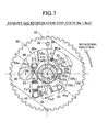
- FIG. 1 is a vertical sectional side view of an internal combustion engine including a valve operating system according to a first embodiment of the present invention
- FIG. 2 is a sectional view taken along the line 2-2 in FIG. 1
- FIG. 3 is a sectional view taken along the line 3-3 in FIG. 1
- FIG. 4 is a sectional view taken along the line 4-4 in FIG. 3
- FIG. 5 is a sectional view taken along the line 5-5 in FIG. 3
- FIG. 6 is a view explaining an operation corresponding to FIG. 5
- FIG. 7 is a sectional view taken along the line 7-7 in FIG. 3
- FIG. 8 is a view explaining an operation corresponding to FIG. 7 ;
- FIG. 1 is a vertical sectional side view of an internal combustion engine including a valve operating system according to a first embodiment of the present invention
- FIG. 2 is a sectional view taken along the line 2-2 in FIG. 1
- FIG. 3 is a sectional view taken along the line 3-3 in FIG. 1
- FIG. 9 is a diagram showing operation regions of a decompression cam member and an exhaust gas recirculation cam member;
- FIG. 10 is a diagram showing a relationship between a rotation angle of a crankshaft and opening/closing timings of an intake valve and an exhaust valve;
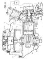
- FIG. 11 is a view showing a second embodiment of the present invention and corresponding to FIG. 2 .
- FIGS. 1 to 10 A first embodiment of the present invention will be explained below based on FIGS. 1 to 10 .
- an engine body 1 of an internal combustion engine E comprises a crankcase 2, a cylinder block 3 extending obliquely upward from one side of the crankcase 2, and a cylinder head 4 joined to an upper end surface of the cylinder block 3.
- the crankcase 2 houses a crankshaft 6 supported on left and right sidewalls thereof via bearings 5 and 5.
- the crankshaft 6 is connected to a piston 7 fitted in a cylinder bore 3a of the cylinder block 3 via a connecting rod 8.
- a flywheel 10 is secured to one end of the crankshaft 6 protruding outside the crankcase 2.
- An annular cooling fan 11 is secured to an outer side surface of the flywheel 10.
- a starting cylinder shaft 12 protruding axially outward from the cooling fan 11 is secured on a center of the flywheel 10.
- a known recoil starter 13 that can engage the starting cylinder shaft 12 to crank the crankshaft 6 is mounted to the crankcase 2 via a bracket 14. The other end of the crankshaft 6 protrudes outside the other sidewall of the crankcase 2 as an output end.
- a combustion chamber 15 connecting to the cylinder bore 3a, and an intake port 16i and an exhaust port 16e having inner ends opening into the combustion chamber 15 are formed, and also an intake valve 17i and an exhaust valve 17e that open and close the intake port 16i and the exhaust port 16e are provided.
- a valve operating system 20 that opens and closes these intake valve 17i and the exhaust valve 17e is provided on a region from the crankcase 2 to the cylinder head 4.
- This valve operating system 20 will be described.
- the timing transmission device 25 comprises a drive gear 31 secured to the crankshaft 6, and a driven gear 32 that is secured to the camshaft 26 and driven by the drive gear 31 at a 1/2 reduction ratio.
- a centrifugal weight 35 formed into a U-shaped so as to surround a half circumference of the camshaft 26 is supported on the driven gear 32 via a pivot 36.
- the centrifugal weight 35 has a center of gravity 37 in a U-shaped bending portion thereof, and oscillates around the pivot 36 between a contracted position A (see FIGS. 4 and 5 ) where the U-shaped bending portion abuts against a hub 32a of the driven gear 32 and an extended position B (see FIG.
- the centrifugal weight 35 is provided with a first movable connection 40 and a second movable connection 41 in a middle portion and an oscillation end thereof. Movable ends 43a and 44a of a first return spring 43 and a second return spring 44 having secured ends connected to a common secured connection 42 of the driven gear 32 and constituted by tension coil springs are connected to the first movable connection 40 and the second movable connection 41.
- the first return spring 43 is adapted to always urge the centrifugal weight 35 radially inward with a predetermined set load Fs1.
- a certain play S is provided between the movable end 44a of the second return spring 44 and the second movable connection 41.
- the second return spring 44 does not resist the oscillation of the centrifugal weight 35 until the centrifugal weight 35 oscillates radially outward through a predetermined angle from the contracted position A.
- the second return spring 44 is adapted to exert a repulsive force that urges the centrifugal weight 35 radially inward in cooperation with the first return spring 43 after the centrifugal weight 35 oscillates radially outward through the predetermined angle from the contracted position A.
- a drive ring 45, a decompression cam member 47, and an exhaust gas recirculation cam member 48 are fitted to the camshaft 26 in order from the side of the centrifugal weight 35 between the centrifugal weight 35 and the exhaust cam 26e.
- the drive ring 45 is rotatably fitted to an outer peripheral surface of the camshaft 26.
- the centrifugal weight 35 has a pair of connection pieces 35a and 35a placed so as to hold a connection protrusion 45c protruding from an outer peripheral surface of the drive ring 45 therebetween from opposite sides along a rotational direction of the drive ring 45.
- the radially outward oscillation of the centrifugal weight 35 causes the rotation of the drive ring 45.
- the decompression cam member 47 and the exhaust gas recirculation cam member 48 are fitted to a pair of guide surfaces 55 and 55 formed on opposite side surfaces of the camshaft 26 and parallel to each other so that these cam members slide along a diameter line of the camshaft 26.
- the operative position C and the inoperative position D are determined by inner end surfaces 56a and 56b of the decompression cam member 47 orthogonal to the guide surfaces 55 and 55 and abutting against the outer peripheral surface of the camshaft 26.
- the exhaust gas recirculation cam member 48 can slide along the guide surfaces 55 and 55 between an inoperative position F ( FIG. 7 ) and an operative position G ( FIG. 8 ).
- the operative position F and the inoperative position G are determined by inner end surfaces 57a and 57b of the exhaust gas recirculation cam member 48 orthogonal to the guide surfaces 55 and 55 and abutting against the outer peripheral surface of the camshaft 26.
- the decompression cam member 47 and the exhaust gas recirculation cam member 48 integrally have, on outer peripheral surfaces thereof, convex cams 47a and 48a much lower than a nose of the exhaust cam 26e.
- the convex cams 47a and 48a protrude outward beyond a base circle of the exhaust cam 26e in the operative positions C and G, and retract into the base circle in the inoperative positions D and F.
- the convex cam 47a of the decompression cam member 47 is placed so as to push up the exhaust tappet 27e in a compression stroke of the engine when the convex cam 47a is in the operative position C.
- the convex cam 48a of the exhaust gas recirculation cam member 48 is placed so as to push up the exhaust tappet 27e in an intake stroke of the engine when the convex cam 48a is in the operative position G.
- a recessed cam 58 that cooperates with the roller 45b is formed in a center part of the inner end surface 56b of the decompression cam member 47 on the side of the convex cam 47a.
- the recessed cam 58 includes: an inclined surface 58a that is pressed by the roller 45b to force the decompression cam member 47 into the operative position C, when the centrifugal weight 35 is held in the contracted position A by an urging force of the first return spring 43; and an arcuate bottom surface 58b that prevents interference with the roller 45b and allows the decompression cam member 47 to move to the inoperative position D, after the centrifugal weight 35 rotates through a predetermined angle or more from the contracted position A (a state in FIG.
- a center of gravity of the decompression cam member 47 is offset from the center thereof to an opposite side from the recessed cam 58.
- a recessed cam 59 that cooperates with the roller 45b is formed in a center part of the inner end surface 57b of the exhaust gas recirculation cam member 48 on the side of the convex cam 48a.
- the recessed cam 59 includes: an arcuate bottom surface 59a that prevents interference with the roller 45b and allows the exhaust gas recirculation cam member 48 to move to the inoperative position F during rotation of the centrifugal weight 35 from the contracted position A through a predetermined angle; and an inclined surface 59b that is pressed by the roller 45b to force the exhaust gas recirculation cam member 48 into the operative position G when the centrifugal weight 35 rotates radially outward through a predetermined angle or more by a centrifugal force.
- a center of gravity of the exhaust gas recirculation cam member 48 is offset from the center thereof to an opposite side from the recessed cam 59.
- the exhaust gas recirculation cam member 48 moves to the inoperative position G by a centrifugal force acting on the center of gravity.
- centrifugal weight 35, the first return spring 43 and the second return spring 44, and the drive ring 45 cooperate with one another to constitute a common centrifugal mechanism 46 that operates the decompression cam member 47 and the exhaust gas recirculation cam member 48.
- the centrifugal mechanism 35, the roller 45b the decompression cam member 47 constitute a decompression device 61, and the centrifugal mechanism 35 and the exhaust gas recirculation cam member 48 constitute an exhaust gas recirculation device 62.
- an ignition plug 21 whose electrode faces the combustion chamber 15 is screwed into the cylinder head 4.
- a carburetor 22 connecting to an outer end of the intake port 16i is mounted to the cylinder head 4.
- An air cleaner 64 is connected to an air inlet of this carburetor 22.
- An exhaust pipe 65 connecting to an outer end of the exhaust port 16e is mounted to the cylinder head 4.
- the exhaust pipe 65 is relatively short, and an exhaust muffler 23 being equipped therewith a three way catalyst converter 66 is connected to a downstream end of the exhaust pipe 65.
- This diaphragm plate 74 has a valve hole 76 that provide communication between the chambers 75a and 75b, and a reed valve plate 77 that opens and closes the valve hole 76 and a stopper plate 78 that restricts an opening limit of the reed valve plate 77 are mounted to the diaphragm plate 74 on a side of the downstream chamber 75b by a screw 79 or a rivet.
- the reed valve plate 77 is generally brought into tight contact with the diaphragm plate 74 by its elasticity to close the valve hole 76, and when pressure in the downstream chamber 75b becomes lower than that in the upstream side, the pressure difference causes the reed valve plate 77 to bend toward the stopper plate 78 side to open the valve hole 76.
- the centrifugal weight 35 is held in the contracted position A by the set load Fs1 of the first return spring 43 as shown in FIGS. 4 and 5 in a starting rotation region a of the engine from the engine rotational speed Ne of zero to a predetermined rotational speed Ne1 lower than an idling rotational speed.
- the centrifugal weight 35 causes the roller 45b of the drive ring 45 positioned via the connection protrusion 45c and the connection pieces 35a and 35a that engage each other, to press the inclined surface 58a of the recessed cam 58 of the decompression cam member 47.
- the decompression cam member 47 is held in the operative position C where the convex cam 47a protrudes outward beyond the base circle of the exhaust cam 26e. Therefore, if the recoil starter 13 is operated to start the internal combustion engine E, the crankshaft 6 is cranked from the starter 13 via the starting cylinder shaft 12, and at the same time, the camshaft 26 is driven via the timing transmission device 25. Consequently, as described above, in the compression stroke of the piston 7, the convex cam 47a of the decompression cam member 47 slightly pushes up the exhaust tappet 27e to slightly open the exhaust valve 17e via the exhaust push rod 28e and the exhaust rocker arm 29e. The timing at this time is shown in FIG. 10 .
- crankshaft 6 can be cranked relatively lightly and swiftly, thereby allowing easy starting of the engine.
- the exhaust valve 17e is controlled to be opened and closed only depending on the operation of the exhaust cam 26e as usual.
- Such a state continues in a low speed operation region b of the engine where the engine rotational speed Ne is Ne1 to Ne2.
- the play S between the second movable connection 41 of the centrifugal weight 35 and the movable end 44a of the second return spring 44 disappears, so that action of the second return spring 44 on the centrifugal weight 35 starts.
- the position of the centrifugal weight 35 is determined by a balance between moment of the centrifugal weight 35 around the pivot 36 due to a return force Fs1 of the first return spring 43 and a return force Fs2 of the second return spring 44, and moment of the centrifugal weight 35 around the pivot 36 due to the centrifugal force Fw, so that an oscillation speed of the centrifugal weight 35 according to an increase in the engine rotational speed Ne slows.
- the centrifugal weight 35 finally reaches the extended position B where the centrifugal weight 35 abuts against the stopper 38 on the driven gear 32, and the further counterclockwise rotation of the drive ring 45 accompanying with it causes the roller 45b to press the inclined surface 59b of the recessed cam 59 of the exhaust gas recirculation cam member 48 and move the exhaust gas recirculation cam member 48 to the operative position G against the centrifugal force. Therefore, the convex cam 48a of the exhaust gas recirculation cam member 48 protrudes beyond the base circle of the exhaust cam 26e.
- the convex cam 48a of the exhaust gas recirculation cam member 48 slightly pushes up the exhaust tappet 27e to slightly open the exhaust valve 17e via the exhaust push rod 28e and the exhaust rocker arm 29e (see FIGS. 1 and 2 ).
- an exhaust gas remaining in the exhaust port 16e is drawn into the cylinder bore 3a, that is, the exhaust gas is recirculated.
- This exhaust gas can suppress an excessive increase in combustion temperature during combustion of air-fuel mixture in a later expansion stroke, to reduce a NOx concentration in the exhaust gas.
- the secondary air drawn into the exhaust port 16e remains in the exhaust port 16e.
- the remaining secondary air reacts with HC and CO in the exhaust gas exhausted to the exhaust port 16e in a later exhaust stroke to reduce HC and CO in the exhaust gas.
- the secondary air drawn into the cylinder bore 3a increases charging efficiency of air/fuel mixture to increase an output of the engine E.
- the exhaust gas passes through the exhaust muffler 23 including the three way catalyst converter 66, thereby further facilitating reduction and removal of NOx and oxidation and removal of HC and CO remaining in the exhaust gas.
- valve box 67 that houses the one-way valve 73 is integrally formed with the head cover 18, thereby eliminating the need for a special support structure for the valve box 67 for the one-way valve 73.
- valve box 67 for the one-way valve 73 is mounted to the exhaust pipe 65, and thus the valve box 67 for the one-way valve 73 can be set using dead space around the exhaust pipe 65.
- the present invention is not limited to the above-mentioned embodiments and may be modified in a variety of ways as long as the modifications do not depart from its gist.
- the exhaust muffler 23 does not need to always be equipped therewith the three way catalyst converter 66.
- an exhaust gas recirculation device that operates so as to partially open an exhaust valve to introduce exhaust gas into a cylinder in an intake stroke is provided; a secondary air passage capable of supplying secondary air to an exhaust passage is connected to the exhaust passage; and a one-way valve opened by negative pressure applied from the cylinder to the exhaust passage following an operation of the exhaust gas recirculation device in the intake stroke is provided in the secondary air passage.
Landscapes
- Engineering & Computer Science (AREA)
- Chemical & Material Sciences (AREA)
- Mechanical Engineering (AREA)
- General Engineering & Computer Science (AREA)
- Combustion & Propulsion (AREA)
- Chemical Kinetics & Catalysis (AREA)
- Health & Medical Sciences (AREA)
- Toxicology (AREA)
- Valve Device For Special Equipments (AREA)
- Exhaust-Gas Circulating Devices (AREA)
- Exhaust Gas After Treatment (AREA)
- Output Control And Ontrol Of Special Type Engine (AREA)
- Exhaust Silencers (AREA)
- Characterised By The Charging Evacuation (AREA)
Abstract
Description
- The present invention relates to an exhaust emission control system for an internal combustion engine which supplies secondary air into an exhaust passage to oxidize and remove HC and CO in an exhaust gas, and which introduces an exhaust gas into a cylinder in an intake stroke to prevent generation of NOx during combustion.
- Japanese Utility Model Registration No.
2535339 2005-240793 - For an internal combustion engine having high muffler back pressure or a short exhaust passage length, sufficient negative pressure by exhaust pulsation is not created in an exhaust passage. Thus, even if the exhaust emission control system disclosed in the above-described Japanese Utility Model Registration No.
2535339 - The present invention is achieved in view of these circumstances, and has an object to provide an exhaust emission control system for an internal combustion engine that allows secondary air to be supplied into an exhaust passage to reduce HC and CO concentrations and also a NOx concentration in an exhaust gas by using an exhaust gas recirculation device without using an air pump regardless of an exhaust system structure of the internal combustion engine.
- In order to achieve the object, according to a first feature of the present invention, there is provided an exhaust emission control system for an internal combustion engine comprising: an exhaust gas recirculation device that operates so as to partially open an exhaust valve to introduce an exhaust gas into a cylinder in an intake stroke; a secondary air passage that is connected to an exhaust passage and can supply secondary air to the exhaust passage; and a one-way valve that is provided in the secondary air passage and opened by negative pressure applied from the cylinder to the exhaust passage following an operation of the exhaust gas recirculation device in the intake stroke.
- According to the first feature of the present invention, the exhaust gas recirculation device operates to partially open the exhaust valve in the intake stoke. This causes an exhaust gas remaining in the exhaust passage to be drawn into the cylinder, that is, the exhaust gas is recirculated. This prevents an excessive increase in combustion temperature during combustion of air-fuel mixture to reduce a NOx concentration in the exhaust gas. Further, in the intake stroke, the exhaust valve is partially opened and the negative pressure in the cylinder is applied to the exhaust passage. The negative pressure opens the one-way valve to bring the secondary air passage into communication with the exhaust passage, the secondary air is drawn into the exhaust passage and further into the cylinder, and the secondary air drawn into the exhaust port remains in the exhaust port. Thus, the remaining secondary air reacts with HC and CO in the exhaust gas exhausted to the exhaust passage in a later exhaust stroke to reduce HC and CO in the exhaust gas. Further, the secondary air drawn into a combustion chamber increases charging efficiency in a cylinder bore to increase an output of the engine. This can reduce HC and CO concentrations and also a NOx concentration in the exhaust gas and increase an output of the engine without using an air pump regardless of an exhaust system structure of the internal combustion engine.
- According to a second feature of the present invention, in addition to the first feature, a valve box that houses the one-way valve is formed in a head cover coupled to a cylinder head.
- According to the second feature of the present invention, the need for a special support structure for the valve box for the one-way valve can be eliminated.
- According to a third feature of the present invention, in addition to the first feature, a valve box that houses the one-way valve is mounted to an exhaust pipe coupled to a cylinder head.
- According to the third feature of the present invention, the valve box for the one-way valve can be set using dead space around the exhaust pipe.
- The exhaust passage corresponds to an exhaust port 16a and an
exhaust pipe 65 of an embodiment of the present invention explained below. The cylinder corresponds to acylinder bore 3a. - The above description, other objects, characteristics and advantages of the present invention will be clear from detailed descriptions which will be provided for the preferred embodiments referring to the attached drawings.
-
FIG. 1 is a vertical sectional side view of an internal combustion engine including a valve operating system according to a first embodiment of the present invention;FIG. 2 is a sectional view taken along the line 2-2 inFIG. 1 ;FIG. 3 is a sectional view taken along the line 3-3 inFIG. 1 ;FIG. 4 is a sectional view taken along the line 4-4 inFIG. 3 ;FIG. 5 is a sectional view taken along the line 5-5 inFIG. 3 ;FIG. 6 is a view explaining an operation corresponding toFIG. 5 ;FIG. 7 is a sectional view taken along the line 7-7 inFIG. 3 ;FIG. 8 is a view explaining an operation corresponding toFIG. 7 ;FIG. 9 is a diagram showing operation regions of a decompression cam member and an exhaust gas recirculation cam member;FIG. 10 is a diagram showing a relationship between a rotation angle of a crankshaft and opening/closing timings of an intake valve and an exhaust valve; andFIG. 11 is a view showing a second embodiment of the present invention and corresponding toFIG. 2 . - A first embodiment of the present invention will be explained below based on
FIGS. 1 to 10 . - In
FIGS. 1 to 3 , an engine body 1 of an internal combustion engine E comprises acrankcase 2, acylinder block 3 extending obliquely upward from one side of thecrankcase 2, and acylinder head 4 joined to an upper end surface of thecylinder block 3. Thecrankcase 2 houses acrankshaft 6 supported on left and right sidewalls thereof viabearings crankshaft 6 is connected to a piston 7 fitted in acylinder bore 3a of thecylinder block 3 via a connectingrod 8. Aflywheel 10 is secured to one end of thecrankshaft 6 protruding outside thecrankcase 2. Anannular cooling fan 11 is secured to an outer side surface of theflywheel 10. Astarting cylinder shaft 12 protruding axially outward from thecooling fan 11 is secured on a center of theflywheel 10. A knownrecoil starter 13 that can engage the startingcylinder shaft 12 to crank thecrankshaft 6 is mounted to thecrankcase 2 via abracket 14. The other end of thecrankshaft 6 protrudes outside the other sidewall of thecrankcase 2 as an output end. - In the
cylinder head 4, acombustion chamber 15 connecting to thecylinder bore 3a, and anintake port 16i and anexhaust port 16e having inner ends opening into thecombustion chamber 15 are formed, and also anintake valve 17i and anexhaust valve 17e that open and close theintake port 16i and theexhaust port 16e are provided. Avalve operating system 20 that opens and closes theseintake valve 17i and theexhaust valve 17e is provided on a region from thecrankcase 2 to thecylinder head 4. - This
valve operating system 20 will be described. - In
FIGS. 1 to 3 , thevalve operating system 20 includes: acamshaft 26 that is supported on the left and right sidewalls of thecrankcase 2 and driven by thecrankshaft 6 via atiming transmission device 25; anintake tappet 27i and anexhaust tappet 27e that are axially slidably supported by thecylinder block 3 to cause flanges 27ia and 27ea at lower ends to abut against anintake cam 26i and anexhaust cam 26e of thecamshaft 26 in a way to allow sliding contact; anintake push rod 28i and anexhaust push rod 28e that have lower ends connecting to upper ends of theintake tappet 27i and theexhaust tappet 27e and upper ends extending above thecylinder head 4; and anintake rocker arm 29i and anexhaust rocker arm 29e that are oscillably supported by a pair ofspherical support members cylinder head 4. Theintake rocker arm 29i is placed so that one end thereof abuts against a head of theintake valve 17i and the other end connects to an upper end of theintake rocker arm 29i. Theexhaust rocker arm 29e is placed so that one end thereof abuts against a head of theexhaust valve 17e and the other end connects to an upper end of theexhaust rocker arm 29e. - Thus, when the
intake cam 26i and theexhaust cam 26e push up the intake tappet 27i and theexhaust tappet 27e, respectively, theintake push rod 28i and theexhaust push rod 28e that move along with these tappets cause theintake rocker arm 29i and theexhaust rocker arm 29e to oscillate in opening directions of theintake valve 17i and theexhaust valve 17e. Anintake valve spring 30i and anexhaust valve spring 30e that urge theintake valve 17i and theexhaust valve 17e in closing directions are mounted to theintake valve 17i and theexhaust valve 17e, respectively. Ahead cover 18 that covers thevalve operating system 20 including theintake rocker arm 29i and theexhaust rocker arm 29e and the like on thecylinder head 4, is joined to an upper end surface of thecylinder head 4. - The
timing transmission device 25 comprises adrive gear 31 secured to thecrankshaft 6, and a drivengear 32 that is secured to thecamshaft 26 and driven by thedrive gear 31 at a 1/2 reduction ratio. As shown inFIGS. 3 and4 , one end of acentrifugal weight 35 formed into a U-shaped so as to surround a half circumference of thecamshaft 26 is supported on the drivengear 32 via apivot 36. Thecentrifugal weight 35 has a center ofgravity 37 in a U-shaped bending portion thereof, and oscillates around thepivot 36 between a contracted position A (seeFIGS. 4 and5 ) where the U-shaped bending portion abuts against ahub 32a of the drivengear 32 and an extended position B (seeFIG. 8 ) where an outer side surface of the U-shaped bending portion abuts against astopper 38 protruding on a side surface of the drivengear 32. Thecentrifugal weight 35 is provided with a firstmovable connection 40 and a secondmovable connection 41 in a middle portion and an oscillation end thereof.Movable ends first return spring 43 and asecond return spring 44 having secured ends connected to a common securedconnection 42 of the drivengear 32 and constituted by tension coil springs are connected to the firstmovable connection 40 and the secondmovable connection 41. Thefirst return spring 43 is adapted to always urge thecentrifugal weight 35 radially inward with a predetermined set load Fs1. A certain play S is provided between themovable end 44a of thesecond return spring 44 and the secondmovable connection 41. Thesecond return spring 44 does not resist the oscillation of thecentrifugal weight 35 until thecentrifugal weight 35 oscillates radially outward through a predetermined angle from the contracted position A. In other words, thesecond return spring 44 is adapted to exert a repulsive force that urges thecentrifugal weight 35 radially inward in cooperation with thefirst return spring 43 after thecentrifugal weight 35 oscillates radially outward through the predetermined angle from the contracted position A. - As shown in
FIG. 3 , adrive ring 45, adecompression cam member 47, and an exhaust gasrecirculation cam member 48 are fitted to thecamshaft 26 in order from the side of thecentrifugal weight 35 between thecentrifugal weight 35 and theexhaust cam 26e. Thedrive ring 45 is rotatably fitted to an outer peripheral surface of thecamshaft 26. Thecentrifugal weight 35 has a pair ofconnection pieces connection protrusion 45c protruding from an outer peripheral surface of thedrive ring 45 therebetween from opposite sides along a rotational direction of thedrive ring 45. The radially outward oscillation of thecentrifugal weight 35 causes the rotation of thedrive ring 45. Thedrive ring 45 has anaxial holding groove 45a in an inner peripheral surface thereof, and, by this holdinggrooves 45a, holds aroller 45b extending axially along thecamshaft 26 between the drivengear 32 and theexhaust cam 26e. Thisroller 45b can roll on the outer peripheral surface of thecamshaft 26 with a rotation of thedrive ring 45 relative to thecamshaft 26. - In
FIGS. 5 to 8 , thedecompression cam member 47 and the exhaust gasrecirculation cam member 48 are fitted to a pair of guide surfaces 55 and 55 formed on opposite side surfaces of thecamshaft 26 and parallel to each other so that these cam members slide along a diameter line of thecamshaft 26. This allows thedecompression cam member 47 to slide along the guide surfaces 55 and 55 between an operative position C (FIG. 5 ) and an inoperative position D (FIG. 5 ). The operative position C and the inoperative position D are determined by inner end surfaces 56a and 56b of thedecompression cam member 47 orthogonal to the guide surfaces 55 and 55 and abutting against the outer peripheral surface of thecamshaft 26. The exhaust gasrecirculation cam member 48 can slide along the guide surfaces 55 and 55 between an inoperative position F (FIG. 7 ) and an operative position G (FIG. 8 ). The operative position F and the inoperative position G are determined by inner end surfaces 57a and 57b of the exhaust gasrecirculation cam member 48 orthogonal to the guide surfaces 55 and 55 and abutting against the outer peripheral surface of thecamshaft 26. - The
decompression cam member 47 and the exhaust gasrecirculation cam member 48 integrally have, on outer peripheral surfaces thereof,convex cams exhaust cam 26e. Theconvex cams exhaust cam 26e in the operative positions C and G, and retract into the base circle in the inoperative positions D and F. Theconvex cam 47a of thedecompression cam member 47 is placed so as to push up theexhaust tappet 27e in a compression stroke of the engine when theconvex cam 47a is in the operative position C. Theconvex cam 48a of the exhaust gasrecirculation cam member 48 is placed so as to push up theexhaust tappet 27e in an intake stroke of the engine when theconvex cam 48a is in the operative position G. - As shown in
FIGS. 5 and6 , a recessedcam 58 that cooperates with theroller 45b is formed in a center part of theinner end surface 56b of thedecompression cam member 47 on the side of theconvex cam 47a. The recessedcam 58 includes: aninclined surface 58a that is pressed by theroller 45b to force thedecompression cam member 47 into the operative position C, when thecentrifugal weight 35 is held in the contracted position A by an urging force of thefirst return spring 43; and anarcuate bottom surface 58b that prevents interference with theroller 45b and allows thedecompression cam member 47 to move to the inoperative position D, after thecentrifugal weight 35 rotates through a predetermined angle or more from the contracted position A (a state inFIG. 6 ). By forming the recessedcam 58, a center of gravity of thedecompression cam member 47 is offset from the center thereof to an opposite side from the recessedcam 58. When theroller 45b comes to a position facing thearcuate bottom surface 58b, thedecompression cam member 47 moves to the inoperative position D by a centrifugal force acting on the center of gravity. - On the other hand, a recessed
cam 59 that cooperates with theroller 45b is formed in a center part of theinner end surface 57b of the exhaust gasrecirculation cam member 48 on the side of theconvex cam 48a. The recessedcam 59 includes: anarcuate bottom surface 59a that prevents interference with theroller 45b and allows the exhaust gasrecirculation cam member 48 to move to the inoperative position F during rotation of thecentrifugal weight 35 from the contracted position A through a predetermined angle; and aninclined surface 59b that is pressed by theroller 45b to force the exhaust gasrecirculation cam member 48 into the operative position G when thecentrifugal weight 35 rotates radially outward through a predetermined angle or more by a centrifugal force. By forming the recessedcam 59, a center of gravity of the exhaust gasrecirculation cam member 48 is offset from the center thereof to an opposite side from the recessedcam 59. When theroller 45b is in a position facing thearcuate bottom surface 59a, the exhaust gasrecirculation cam member 48 moves to the inoperative position G by a centrifugal force acting on the center of gravity. - In the above description, the
centrifugal weight 35, thefirst return spring 43 and thesecond return spring 44, and thedrive ring 45 cooperate with one another to constitute a commoncentrifugal mechanism 46 that operates thedecompression cam member 47 and the exhaust gasrecirculation cam member 48. Thecentrifugal mechanism 35, theroller 45b thedecompression cam member 47 constitute adecompression device 61, and thecentrifugal mechanism 35 and the exhaust gasrecirculation cam member 48 constitute an exhaustgas recirculation device 62. - Referring again to
FIG. 2 , anignition plug 21 whose electrode faces thecombustion chamber 15 is screwed into thecylinder head 4. Acarburetor 22 connecting to an outer end of theintake port 16i is mounted to thecylinder head 4. Anair cleaner 64 is connected to an air inlet of thiscarburetor 22. Anexhaust pipe 65 connecting to an outer end of theexhaust port 16e is mounted to thecylinder head 4. Theexhaust pipe 65 is relatively short, and anexhaust muffler 23 being equipped therewith a threeway catalyst converter 66 is connected to a downstream end of theexhaust pipe 65. - A
valve box 67 is formed in thehead cover 18 that is coupled to an upper end of thecylinder head 4 and covers thevalve operating system 20. Thisvalve box 67 is constituted by a lowerbox half body 67a integrally formed with a ceiling wall of thehead cover 18 and having an open upper surface and an upperbox half body 67b coupled to the lowerbox half body 67a by a bolt. Ajoint pipe 69 to which anair tube 68 extending from theair cleaner 64 is connected is integrally formed with one side of the upperbox half body 67b. The lowerbox half body 67a communicates with theintake port 16i via anair hole 70 provided in thecylinder head 4 and thehead cover 18. Thevalve box 67, theair tube 68, and theair hole 70 constitute a secondary air passage 71. - In the
valve box 67, a one-way valve 73 is provided that is constituted by a reed valve and opened when negative pressure is created in theexhaust port 16e to bring the secondary air passage 71 into communication. The one-way valve 73 is held between the lower and upperbox half bodies diaphragm plate 74 that partitions the inside of thevalve box 67 into anupstream chamber 75a on a side of theair tube 68 and adownstream chamber 75b on a side of theair hole 70. Thisdiaphragm plate 74 has avalve hole 76 that provide communication between thechambers reed valve plate 77 that opens and closes thevalve hole 76 and astopper plate 78 that restricts an opening limit of thereed valve plate 77 are mounted to thediaphragm plate 74 on a side of thedownstream chamber 75b by ascrew 79 or a rivet. Thereed valve plate 77 is generally brought into tight contact with thediaphragm plate 74 by its elasticity to close thevalve hole 76, and when pressure in thedownstream chamber 75b becomes lower than that in the upstream side, the pressure difference causes thereed valve plate 77 to bend toward thestopper plate 78 side to open thevalve hole 76. - Next, an operation of this embodiment will be described.
- When the
crankshaft 6 rotates, thecamshaft 26 is driven by thecrankshaft 6 via thetiming transmission device 25 at a 1/2 reduction ratio. In the intake stroke, theintake cam 26i pushes up theintake push rod 28i via theintake tappet 27i, causes theintake rocker arm 29i to oscillate, and forces theintake valve 17i to open against an urging force of theintake valve spring 30i. In the exhaust stroke, theexhaust cam 26e pushes up theexhaust push rod 28e via theexhaust tappet 27e, causes theexhaust rocker arm 29e to oscillate, and forces theexhaust valve 17e to open thesecond return spring 44. Such opening/closing timings of theintake valve 17i and theexhaust valve 17e are shown inFIG. 10 . - In
FIG. 9 , thecentrifugal weight 35 is held in the contracted position A by the set load Fs1 of thefirst return spring 43 as shown inFIGS. 4 and5 in a starting rotation region a of the engine from the engine rotational speed Ne of zero to a predetermined rotational speed Ne1 lower than an idling rotational speed. At this time, thecentrifugal weight 35 causes theroller 45b of thedrive ring 45 positioned via theconnection protrusion 45c and theconnection pieces inclined surface 58a of the recessedcam 58 of thedecompression cam member 47. Thus, thedecompression cam member 47 is held in the operative position C where theconvex cam 47a protrudes outward beyond the base circle of theexhaust cam 26e. Therefore, if therecoil starter 13 is operated to start the internal combustion engine E, thecrankshaft 6 is cranked from thestarter 13 via the startingcylinder shaft 12, and at the same time, thecamshaft 26 is driven via thetiming transmission device 25. Consequently, as described above, in the compression stroke of the piston 7, theconvex cam 47a of thedecompression cam member 47 slightly pushes up theexhaust tappet 27e to slightly open theexhaust valve 17e via theexhaust push rod 28e and theexhaust rocker arm 29e. The timing at this time is shown inFIG. 10 . As a result, a part of compression gas in thecylinder bore 3a is discharged through theexhaust port 16e to prevent an increase in a compression pressure of the gas, thus reducing an operation load of thestarter 13. Therefore, thecrankshaft 6 can be cranked relatively lightly and swiftly, thereby allowing easy starting of the engine. - When the engine starts and the engine rotational speed Ne exits the starting rotation region a, as shown in
FIG. 6 , moment of thecentrifugal weight 35 around thepivot 36 by a centrifugal force Fw overcomes moment of thecentrifugal weight 35 around thepivot 36 by the set load Fs1 of thefirst return spring 43, to cause thecentrifugal weight 35 to oscillate radially outward from the contracted position A. Such oscillation is transmitted from theconnection piece 35a to theconnection protrusion 45c, to rotate thedrive ring 45 counterclockwise and move theroller 45b to a position facing thebottom surface 58b of the recessedcam 58 of the exhaust gasrecirculation cam member 48. Thus, thedecompression cam member 47 moves to the inoperative position D by the centrifugal force without interference by theroller 45b, thereby retracting theconvex cam 47a into the base circle of theexhaust cam 26e. - During this process, in the exhaust gas
recirculation cam member 48, thebottom surface 59a of the recessedcam 59 faces theroller 45b of thedrive ring 45 as shown inFIG. 7 , and thus the exhaust gasrecirculation cam member 48 is held in the inoperative position F by the centrifugal force without interference by theroller 45b, thereby retracting theconvex cam 48a into the base circle of theexhaust cam 26e. - Thus, the
exhaust valve 17e is controlled to be opened and closed only depending on the operation of theexhaust cam 26e as usual. Such a state continues in a low speed operation region b of the engine where the engine rotational speed Ne is Ne1 to Ne2. With the movement of thecentrifugal weight 35 at about the time when the engine rotational speed Ne reaches Ne2, as shown inFIG. 7 , the play S between the secondmovable connection 41 of thecentrifugal weight 35 and themovable end 44a of thesecond return spring 44 disappears, so that action of thesecond return spring 44 on thecentrifugal weight 35 starts. Thus, after that, the position of thecentrifugal weight 35 is determined by a balance between moment of thecentrifugal weight 35 around thepivot 36 due to a return force Fs1 of thefirst return spring 43 and a return force Fs2 of thesecond return spring 44, and moment of thecentrifugal weight 35 around thepivot 36 due to the centrifugal force Fw, so that an oscillation speed of thecentrifugal weight 35 according to an increase in the engine rotational speed Ne slows. - Next, when the engine rotational speed Ne exceeds Ne2 and the internal combustion engine E enters a high speed operation region C, the
centrifugal weight 35 finally reaches the extended position B where thecentrifugal weight 35 abuts against thestopper 38 on the drivengear 32, and the further counterclockwise rotation of thedrive ring 45 accompanying with it causes theroller 45b to press theinclined surface 59b of the recessedcam 59 of the exhaust gasrecirculation cam member 48 and move the exhaust gasrecirculation cam member 48 to the operative position G against the centrifugal force. Therefore, theconvex cam 48a of the exhaust gasrecirculation cam member 48 protrudes beyond the base circle of theexhaust cam 26e. Thus, as described above, in the intake stroke, theconvex cam 48a of the exhaust gasrecirculation cam member 48 slightly pushes up theexhaust tappet 27e to slightly open theexhaust valve 17e via theexhaust push rod 28e and theexhaust rocker arm 29e (seeFIGS. 1 and2 ). As a result, an exhaust gas remaining in theexhaust port 16e is drawn into thecylinder bore 3a, that is, the exhaust gas is recirculated. This exhaust gas can suppress an excessive increase in combustion temperature during combustion of air-fuel mixture in a later expansion stroke, to reduce a NOx concentration in the exhaust gas. - In the above-described intake stroke, as shown in
FIGS. 1 and2 , theexhaust valve 17e is slightly opened to apply the negative pressure in the cylinder bore 3a to theexhaust port 16e. This negative pressure is transferred from theair hole 70 to thedownstream chamber 75b of thevalve box 67 to create the pressure difference between thedownstream chamber 75b and theupstream chamber 75a. Thus, thereed valve plate 77 bends toward thedownstream chamber 75b to open thevalve hole 76 in thediaphragm plate 74. Specifically, the one-way valve 73 is opened to bring the secondary air passage 71 into communication with theexhaust port 16e, and thus secondary air filtered by theair cleaner 64 is drawn through the secondary air passage 71 into theexhaust port 16e and further into thecylinder bore 3a. In a short time thereafter, the intake stroke finishes and the intake andexhaust valves exhaust port 16e remains in theexhaust port 16e. Thus, the remaining secondary air reacts with HC and CO in the exhaust gas exhausted to theexhaust port 16e in a later exhaust stroke to reduce HC and CO in the exhaust gas. Further, the secondary air drawn into thecylinder bore 3a increases charging efficiency of air/fuel mixture to increase an output of the engine E. - This can reduce HC and CO concentrations and also a NOx concentration in the exhaust gas and increase an output of the engine without using an air pump regardless of an exhaust system structure of the internal combustion engine. The exhaust gas passes through the
exhaust muffler 23 including the threeway catalyst converter 66, thereby further facilitating reduction and removal of NOx and oxidation and removal of HC and CO remaining in the exhaust gas. - Now, in the first embodiment, the
valve box 67 that houses the one-way valve 73 is integrally formed with thehead cover 18, thereby eliminating the need for a special support structure for thevalve box 67 for the one-way valve 73. - Next, a second embodiment of the present invention shown in
FIG. 11 will be explained. - In this second embodiment, a
valve box 67 that houses a one-way valve 73 is secured by ascrew 80 to anexhaust pipe 65 connected to acylinder head 4, and ashort air hole 70 connecting to adownstream chamber 75b of thevalve box 67 opens into theexhaust pipe 65. Other configurations are the same as in the first embodiment. Thus, components corresponding to those in the first embodiment are denoted by the same reference numerals inFIG. 11 , and overlapping descriptions will be omitted. - According to this second embodiment, the
valve box 67 for the one-way valve 73 is mounted to theexhaust pipe 65, and thus thevalve box 67 for the one-way valve 73 can be set using dead space around theexhaust pipe 65. - The present invention is not limited to the above-mentioned embodiments and may be modified in a variety of ways as long as the modifications do not depart from its gist. For example, the
exhaust muffler 23 does not need to always be equipped therewith the threeway catalyst converter 66. - In an exhaust emission control system for an internal combustion engine, an exhaust gas recirculation device that operates so as to partially open an exhaust valve to introduce exhaust gas into a cylinder in an intake stroke is provided; a secondary air passage capable of supplying secondary air to an exhaust passage is connected to the exhaust passage; and a one-way valve opened by negative pressure applied from the cylinder to the exhaust passage following an operation of the exhaust gas recirculation device in the intake stroke is provided in the secondary air passage. Accordingly, it is possible to provide an exhaust emission control system for an internal combustion engine that allows secondary air to be supplied into an exhaust passage to reduce HC and CO concentrations and also a NOx concentration in an exhaust gas without using an air pump regardless of an exhaust system structure of the internal combustion engine.
Claims (3)
- An exhaust emission control system for an internal combustion engine comprising:an exhaust gas recirculation device that operates so as to partially open an exhaust valve to introduce an exhaust gas into a cylinder in an intake stroke;a secondary air passage that is connected to an exhaust passage and can supply secondary air to the exhaust passage; anda one-way valve that is provided in the secondary air passage and opened by negative pressure applied from the cylinder to the exhaust passage following an operation of the exhaust gas recirculation device in the intake stroke.
- The exhaust emission control system for an internal combustion engine according to claim 1, wherein a valve box that houses the one-way valve is formed in a head cover coupled to a cylinder head.
- The exhaust emission control system for an internal combustion engine according to claim 1, wherein a valve box that houses the one-way valve is mounted to an exhaust pipe coupled to a cylinder head.
Applications Claiming Priority (1)
| Application Number | Priority Date | Filing Date | Title |
|---|---|---|---|
| JP2008131300A JP2009281159A (en) | 2008-05-19 | 2008-05-19 | Exhaust emission control device of internal combustion engine |
Publications (2)
| Publication Number | Publication Date |
|---|---|
| EP2123876A1 true EP2123876A1 (en) | 2009-11-25 |
| EP2123876B1 EP2123876B1 (en) | 2010-09-22 |
Family
ID=40937419
Family Applications (1)
| Application Number | Title | Priority Date | Filing Date |
|---|---|---|---|
| EP09160395A Not-in-force EP2123876B1 (en) | 2008-05-19 | 2009-05-15 | Exhaust emission controll system for internal combustion engine |
Country Status (5)
| Country | Link |
|---|---|
| US (1) | US8234856B2 (en) |
| EP (1) | EP2123876B1 (en) |
| JP (1) | JP2009281159A (en) |
| AT (1) | ATE482330T1 (en) |
| DE (1) | DE602009000217D1 (en) |
Cited By (1)
| Publication number | Priority date | Publication date | Assignee | Title |
|---|---|---|---|---|
| EP2386743A1 (en) * | 2010-05-12 | 2011-11-16 | IFP Energies nouvelles | Method for controlling fresh air supply to the exhaust system of an internal combustion engine |
Families Citing this family (5)
| Publication number | Priority date | Publication date | Assignee | Title |
|---|---|---|---|---|
| EP2479389B1 (en) * | 2009-09-14 | 2014-07-23 | Honda Motor Co., Ltd. | Valve gear of internal combustion engine |
| JP5833910B2 (en) * | 2011-12-19 | 2015-12-16 | スターテング工業株式会社 | Recoil starter mechanism |
| JP2014173518A (en) * | 2013-03-11 | 2014-09-22 | Honda Motor Co Ltd | Exhaust purification device of utility engine |
| WO2020008611A1 (en) * | 2018-07-05 | 2020-01-09 | 本田技研工業株式会社 | Engine decompression device and engine |
| JP2021080872A (en) * | 2019-11-19 | 2021-05-27 | 川崎重工業株式会社 | Catalyst unit and exhaust structure for engine including the same |
Citations (5)
| Publication number | Priority date | Publication date | Assignee | Title |
|---|---|---|---|---|
| DE2640941A1 (en) * | 1975-09-11 | 1977-03-31 | Nissan Motor | MIXTURE CONTROL SYSTEM |
| FR2687730A1 (en) * | 1992-02-21 | 1993-08-27 | Renault | ADDITIONAL GAS INTRODUCTION DEVICE FOR INTERNAL COMBUSTION ENGINE. |
| JP2535339B2 (en) | 1985-12-20 | 1996-09-18 | ヤゴテック アーゲー | Device for controlling the speed of active substances |
| JP2005240793A (en) | 2004-01-26 | 2005-09-08 | Honda Motor Co Ltd | Valve operating device for internal combustion engine |
| JP2006329003A (en) * | 2005-05-24 | 2006-12-07 | Toyota Motor Corp | Secondary air supply device for internal combustion engine |
Family Cites Families (10)
| Publication number | Priority date | Publication date | Assignee | Title |
|---|---|---|---|---|
| JPS52109027A (en) * | 1976-03-08 | 1977-09-12 | Toyota Motor Corp | After-fire preventing device for engine |
| JPS609383Y2 (en) * | 1976-05-07 | 1985-04-03 | 日産自動車株式会社 | Spark-ignition multi-cylinder internal combustion engine |
| JPS5540338Y2 (en) * | 1977-02-25 | 1980-09-20 | ||
| US4325346A (en) * | 1980-09-05 | 1982-04-20 | Suzuki Jidosha Kogyo Kabushiki Kaisha | Four-cycle internal combustion engine |
| JPS58106120A (en) * | 1981-12-18 | 1983-06-24 | Honda Motor Co Ltd | Exhaust gas purification device for internal combustion engines in motorcycles |
| JPS6019911A (en) * | 1983-07-12 | 1985-02-01 | Nippon Soken Inc | Secondary air introduction pipe |
| JP2535339Y2 (en) | 1991-07-03 | 1997-05-14 | 本田技研工業株式会社 | Secondary air introduction device for engine |
| JP2001355440A (en) * | 2000-06-15 | 2001-12-26 | Mitsubishi Heavy Ind Ltd | Secondary air lead-in device for engine |
| JP4411927B2 (en) * | 2003-10-20 | 2010-02-10 | トヨタ自動車株式会社 | Control device and control method for internal combustion engine |
| JP4704242B2 (en) * | 2006-02-28 | 2011-06-15 | 本田技研工業株式会社 | Secondary air supply device for exhaust purification |
-
2008
- 2008-05-19 JP JP2008131300A patent/JP2009281159A/en active Pending
-
2009
- 2009-05-15 AT AT09160395T patent/ATE482330T1/en not_active IP Right Cessation
- 2009-05-15 DE DE602009000217T patent/DE602009000217D1/en active Active
- 2009-05-15 EP EP09160395A patent/EP2123876B1/en not_active Not-in-force
- 2009-05-18 US US12/467,554 patent/US8234856B2/en not_active Expired - Fee Related
Patent Citations (5)
| Publication number | Priority date | Publication date | Assignee | Title |
|---|---|---|---|---|
| DE2640941A1 (en) * | 1975-09-11 | 1977-03-31 | Nissan Motor | MIXTURE CONTROL SYSTEM |
| JP2535339B2 (en) | 1985-12-20 | 1996-09-18 | ヤゴテック アーゲー | Device for controlling the speed of active substances |
| FR2687730A1 (en) * | 1992-02-21 | 1993-08-27 | Renault | ADDITIONAL GAS INTRODUCTION DEVICE FOR INTERNAL COMBUSTION ENGINE. |
| JP2005240793A (en) | 2004-01-26 | 2005-09-08 | Honda Motor Co Ltd | Valve operating device for internal combustion engine |
| JP2006329003A (en) * | 2005-05-24 | 2006-12-07 | Toyota Motor Corp | Secondary air supply device for internal combustion engine |
Cited By (2)
| Publication number | Priority date | Publication date | Assignee | Title |
|---|---|---|---|---|
| EP2386743A1 (en) * | 2010-05-12 | 2011-11-16 | IFP Energies nouvelles | Method for controlling fresh air supply to the exhaust system of an internal combustion engine |
| FR2960023A1 (en) * | 2010-05-12 | 2011-11-18 | Inst Francais Du Petrole | METHOD OF CONTROLLING THE INJECTION OF FRESH AIR TO THE EXHAUST OF AN INTERNAL COMBUSTION ENGINE, IN PARTICULAR A MOTOR VEHICLE. |
Also Published As
| Publication number | Publication date |
|---|---|
| US8234856B2 (en) | 2012-08-07 |
| US20090282819A1 (en) | 2009-11-19 |
| EP2123876B1 (en) | 2010-09-22 |
| JP2009281159A (en) | 2009-12-03 |
| ATE482330T1 (en) | 2010-10-15 |
| DE602009000217D1 (en) | 2010-11-04 |
Similar Documents
| Publication | Publication Date | Title |
|---|---|---|
| US9212574B2 (en) | Valve operating system for internal combustion engine | |
| EP2123876B1 (en) | Exhaust emission controll system for internal combustion engine | |
| KR100815311B1 (en) | Engine decompression system | |
| US7131407B2 (en) | Valve operating system for internal combustion engine | |
| JP4024121B2 (en) | Valve operating device for internal combustion engine | |
| US7472685B2 (en) | Control method and control apparatus of internal combustion engine | |
| JP3944053B2 (en) | Variable compression ratio engine | |
| JP5142804B2 (en) | Valve operating device for internal combustion engine | |
| JP2008025491A (en) | Internal combustion engine | |
| AU762252B2 (en) | Decompression unit for internal combustion engine | |
| TW200530490A (en) | Valve operating device for internal combustion engine | |
| JP3959016B2 (en) | Variable compression ratio engine | |
| JP5205570B2 (en) | Variable valve opening angle variable system with variable lift mechanism |
Legal Events
| Date | Code | Title | Description |
|---|---|---|---|
| PUAI | Public reference made under article 153(3) epc to a published international application that has entered the european phase |
Free format text: ORIGINAL CODE: 0009012 |
|
| 17P | Request for examination filed |
Effective date: 20090515 |
|
| AK | Designated contracting states |
Kind code of ref document: A1 Designated state(s): AT BE BG CH CY CZ DE DK EE ES FI FR GB GR HR HU IE IS IT LI LT LU LV MC MK MT NL NO PL PT RO SE SI SK TR |
|
| GRAP | Despatch of communication of intention to grant a patent |
Free format text: ORIGINAL CODE: EPIDOSNIGR1 |
|
| GRAJ | Information related to disapproval of communication of intention to grant by the applicant or resumption of examination proceedings by the epo deleted |
Free format text: ORIGINAL CODE: EPIDOSDIGR1 |
|
| GRAP | Despatch of communication of intention to grant a patent |
Free format text: ORIGINAL CODE: EPIDOSNIGR1 |
|
| GRAC | Information related to communication of intention to grant a patent modified |
Free format text: ORIGINAL CODE: EPIDOSCIGR1 |
|
| GRAS | Grant fee paid |
Free format text: ORIGINAL CODE: EPIDOSNIGR3 |
|
| GRAA | (expected) grant |
Free format text: ORIGINAL CODE: 0009210 |
|
| AK | Designated contracting states |
Kind code of ref document: B1 Designated state(s): AT BE BG CH CY CZ DE DK EE ES FI FR GB GR HR HU IE IS IT LI LT LU LV MC MK MT NL NO PL PT RO SE SI SK TR |
|
| REG | Reference to a national code |
Ref country code: GB Ref legal event code: FG4D |
|
| REG | Reference to a national code |
Ref country code: CH Ref legal event code: EP |
|
| REG | Reference to a national code |
Ref country code: IE Ref legal event code: FG4D |
|
| REF | Corresponds to: |
Ref document number: 602009000217 Country of ref document: DE Date of ref document: 20101104 Kind code of ref document: P |
|
| PG25 | Lapsed in a contracting state [announced via postgrant information from national office to epo] |
Ref country code: FI Free format text: LAPSE BECAUSE OF FAILURE TO SUBMIT A TRANSLATION OF THE DESCRIPTION OR TO PAY THE FEE WITHIN THE PRESCRIBED TIME-LIMIT Effective date: 20100922 Ref country code: LT Free format text: LAPSE BECAUSE OF FAILURE TO SUBMIT A TRANSLATION OF THE DESCRIPTION OR TO PAY THE FEE WITHIN THE PRESCRIBED TIME-LIMIT Effective date: 20100922 Ref country code: AT Free format text: LAPSE BECAUSE OF FAILURE TO SUBMIT A TRANSLATION OF THE DESCRIPTION OR TO PAY THE FEE WITHIN THE PRESCRIBED TIME-LIMIT Effective date: 20100922 Ref country code: NO Free format text: LAPSE BECAUSE OF FAILURE TO SUBMIT A TRANSLATION OF THE DESCRIPTION OR TO PAY THE FEE WITHIN THE PRESCRIBED TIME-LIMIT Effective date: 20101222 |
|
| REG | Reference to a national code |
Ref country code: NL Ref legal event code: VDEP Effective date: 20100922 |
|
| LTIE | Lt: invalidation of european patent or patent extension |
Effective date: 20100922 |
|
| PG25 | Lapsed in a contracting state [announced via postgrant information from national office to epo] |
Ref country code: PL Free format text: LAPSE BECAUSE OF FAILURE TO SUBMIT A TRANSLATION OF THE DESCRIPTION OR TO PAY THE FEE WITHIN THE PRESCRIBED TIME-LIMIT Effective date: 20100922 Ref country code: HR Free format text: LAPSE BECAUSE OF FAILURE TO SUBMIT A TRANSLATION OF THE DESCRIPTION OR TO PAY THE FEE WITHIN THE PRESCRIBED TIME-LIMIT Effective date: 20100922 Ref country code: SI Free format text: LAPSE BECAUSE OF FAILURE TO SUBMIT A TRANSLATION OF THE DESCRIPTION OR TO PAY THE FEE WITHIN THE PRESCRIBED TIME-LIMIT Effective date: 20100922 |
|
| PG25 | Lapsed in a contracting state [announced via postgrant information from national office to epo] |
Ref country code: LV Free format text: LAPSE BECAUSE OF FAILURE TO SUBMIT A TRANSLATION OF THE DESCRIPTION OR TO PAY THE FEE WITHIN THE PRESCRIBED TIME-LIMIT Effective date: 20100922 Ref country code: SE Free format text: LAPSE BECAUSE OF FAILURE TO SUBMIT A TRANSLATION OF THE DESCRIPTION OR TO PAY THE FEE WITHIN THE PRESCRIBED TIME-LIMIT Effective date: 20100922 Ref country code: GR Free format text: LAPSE BECAUSE OF FAILURE TO SUBMIT A TRANSLATION OF THE DESCRIPTION OR TO PAY THE FEE WITHIN THE PRESCRIBED TIME-LIMIT Effective date: 20101223 |
|
| PG25 | Lapsed in a contracting state [announced via postgrant information from national office to epo] |
Ref country code: RO Free format text: LAPSE BECAUSE OF FAILURE TO SUBMIT A TRANSLATION OF THE DESCRIPTION OR TO PAY THE FEE WITHIN THE PRESCRIBED TIME-LIMIT Effective date: 20100922 Ref country code: CZ Free format text: LAPSE BECAUSE OF FAILURE TO SUBMIT A TRANSLATION OF THE DESCRIPTION OR TO PAY THE FEE WITHIN THE PRESCRIBED TIME-LIMIT Effective date: 20100922 Ref country code: IS Free format text: LAPSE BECAUSE OF FAILURE TO SUBMIT A TRANSLATION OF THE DESCRIPTION OR TO PAY THE FEE WITHIN THE PRESCRIBED TIME-LIMIT Effective date: 20110122 Ref country code: EE Free format text: LAPSE BECAUSE OF FAILURE TO SUBMIT A TRANSLATION OF THE DESCRIPTION OR TO PAY THE FEE WITHIN THE PRESCRIBED TIME-LIMIT Effective date: 20100922 Ref country code: NL Free format text: LAPSE BECAUSE OF FAILURE TO SUBMIT A TRANSLATION OF THE DESCRIPTION OR TO PAY THE FEE WITHIN THE PRESCRIBED TIME-LIMIT Effective date: 20100922 Ref country code: SK Free format text: LAPSE BECAUSE OF FAILURE TO SUBMIT A TRANSLATION OF THE DESCRIPTION OR TO PAY THE FEE WITHIN THE PRESCRIBED TIME-LIMIT Effective date: 20100922 Ref country code: PT Free format text: LAPSE BECAUSE OF FAILURE TO SUBMIT A TRANSLATION OF THE DESCRIPTION OR TO PAY THE FEE WITHIN THE PRESCRIBED TIME-LIMIT Effective date: 20110124 |
|
| PG25 | Lapsed in a contracting state [announced via postgrant information from national office to epo] |
Ref country code: BE Free format text: LAPSE BECAUSE OF FAILURE TO SUBMIT A TRANSLATION OF THE DESCRIPTION OR TO PAY THE FEE WITHIN THE PRESCRIBED TIME-LIMIT Effective date: 20100922 |
|
| PG25 | Lapsed in a contracting state [announced via postgrant information from national office to epo] |
Ref country code: ES Free format text: LAPSE BECAUSE OF FAILURE TO SUBMIT A TRANSLATION OF THE DESCRIPTION OR TO PAY THE FEE WITHIN THE PRESCRIBED TIME-LIMIT Effective date: 20110102 |
|
| PLBE | No opposition filed within time limit |
Free format text: ORIGINAL CODE: 0009261 |
|
| STAA | Information on the status of an ep patent application or granted ep patent |
Free format text: STATUS: NO OPPOSITION FILED WITHIN TIME LIMIT |
|
| 26N | No opposition filed |
Effective date: 20110623 |
|
| PG25 | Lapsed in a contracting state [announced via postgrant information from national office to epo] |
Ref country code: DK Free format text: LAPSE BECAUSE OF FAILURE TO SUBMIT A TRANSLATION OF THE DESCRIPTION OR TO PAY THE FEE WITHIN THE PRESCRIBED TIME-LIMIT Effective date: 20100922 |
|
| REG | Reference to a national code |
Ref country code: DE Ref legal event code: R097 Ref document number: 602009000217 Country of ref document: DE Effective date: 20110623 |
|
| PG25 | Lapsed in a contracting state [announced via postgrant information from national office to epo] |
Ref country code: MC Free format text: LAPSE BECAUSE OF NON-PAYMENT OF DUE FEES Effective date: 20110531 Ref country code: MT Free format text: LAPSE BECAUSE OF FAILURE TO SUBMIT A TRANSLATION OF THE DESCRIPTION OR TO PAY THE FEE WITHIN THE PRESCRIBED TIME-LIMIT Effective date: 20100922 |
|
| REG | Reference to a national code |
Ref country code: IE Ref legal event code: MM4A |
|
| PG25 | Lapsed in a contracting state [announced via postgrant information from national office to epo] |
Ref country code: IE Free format text: LAPSE BECAUSE OF NON-PAYMENT OF DUE FEES Effective date: 20110515 |
|
| PG25 | Lapsed in a contracting state [announced via postgrant information from national office to epo] |
Ref country code: MK Free format text: LAPSE BECAUSE OF FAILURE TO SUBMIT A TRANSLATION OF THE DESCRIPTION OR TO PAY THE FEE WITHIN THE PRESCRIBED TIME-LIMIT Effective date: 20100922 |
|
| PG25 | Lapsed in a contracting state [announced via postgrant information from national office to epo] |
Ref country code: CY Free format text: LAPSE BECAUSE OF EXPIRATION OF PROTECTION Effective date: 20100922 Ref country code: LU Free format text: LAPSE BECAUSE OF NON-PAYMENT OF DUE FEES Effective date: 20110515 |
|
| PGFP | Annual fee paid to national office [announced via postgrant information from national office to epo] |
Ref country code: GB Payment date: 20130515 Year of fee payment: 5 Ref country code: DE Payment date: 20130515 Year of fee payment: 5 |
|
| PGFP | Annual fee paid to national office [announced via postgrant information from national office to epo] |
Ref country code: FR Payment date: 20130531 Year of fee payment: 5 Ref country code: IT Payment date: 20130520 Year of fee payment: 5 |
|
| PG25 | Lapsed in a contracting state [announced via postgrant information from national office to epo] |
Ref country code: TR Free format text: LAPSE BECAUSE OF FAILURE TO SUBMIT A TRANSLATION OF THE DESCRIPTION OR TO PAY THE FEE WITHIN THE PRESCRIBED TIME-LIMIT Effective date: 20100922 Ref country code: BG Free format text: LAPSE BECAUSE OF FAILURE TO SUBMIT A TRANSLATION OF THE DESCRIPTION OR TO PAY THE FEE WITHIN THE PRESCRIBED TIME-LIMIT Effective date: 20101222 |
|
| PG25 | Lapsed in a contracting state [announced via postgrant information from national office to epo] |
Ref country code: HU Free format text: LAPSE BECAUSE OF FAILURE TO SUBMIT A TRANSLATION OF THE DESCRIPTION OR TO PAY THE FEE WITHIN THE PRESCRIBED TIME-LIMIT Effective date: 20100922 |
|
| REG | Reference to a national code |
Ref country code: CH Ref legal event code: PL |
|
| PG25 | Lapsed in a contracting state [announced via postgrant information from national office to epo] |
Ref country code: CH Free format text: LAPSE BECAUSE OF NON-PAYMENT OF DUE FEES Effective date: 20130531 Ref country code: LI Free format text: LAPSE BECAUSE OF NON-PAYMENT OF DUE FEES Effective date: 20130531 |
|
| REG | Reference to a national code |
Ref country code: DE Ref legal event code: R119 Ref document number: 602009000217 Country of ref document: DE |
|
| GBPC | Gb: european patent ceased through non-payment of renewal fee |
Effective date: 20140515 |
|
| REG | Reference to a national code |
Ref country code: FR Ref legal event code: ST Effective date: 20150130 |
|
| REG | Reference to a national code |
Ref country code: DE Ref legal event code: R119 Ref document number: 602009000217 Country of ref document: DE Effective date: 20141202 |
|
| PG25 | Lapsed in a contracting state [announced via postgrant information from national office to epo] |
Ref country code: DE Free format text: LAPSE BECAUSE OF NON-PAYMENT OF DUE FEES Effective date: 20141202 Ref country code: IT Free format text: LAPSE BECAUSE OF NON-PAYMENT OF DUE FEES Effective date: 20140515 |
|
| PG25 | Lapsed in a contracting state [announced via postgrant information from national office to epo] |
Ref country code: FR Free format text: LAPSE BECAUSE OF NON-PAYMENT OF DUE FEES Effective date: 20140602 Ref country code: GB Free format text: LAPSE BECAUSE OF NON-PAYMENT OF DUE FEES Effective date: 20140515 |