EP2123866A2 - Valve timing control device - Google Patents
Valve timing control device Download PDFInfo
- Publication number
- EP2123866A2 EP2123866A2 EP09004046A EP09004046A EP2123866A2 EP 2123866 A2 EP2123866 A2 EP 2123866A2 EP 09004046 A EP09004046 A EP 09004046A EP 09004046 A EP09004046 A EP 09004046A EP 2123866 A2 EP2123866 A2 EP 2123866A2
- Authority
- EP
- European Patent Office
- Prior art keywords
- valving element
- chamber
- passageway
- state
- leak
- Prior art date
- Legal status (The legal status is an assumption and is not a legal conclusion. Google has not performed a legal analysis and makes no representation as to the accuracy of the status listed.)
- Granted
Links
- 238000006073 displacement reaction Methods 0.000 claims abstract description 100
- 239000012530 fluid Substances 0.000 claims abstract description 60
- 230000002093 peripheral effect Effects 0.000 claims description 33
- 238000000638 solvent extraction Methods 0.000 claims description 26
- 238000002485 combustion reaction Methods 0.000 claims description 13
- 238000007599 discharging Methods 0.000 claims description 11
- 230000000903 blocking effect Effects 0.000 claims description 2
- 238000010276 construction Methods 0.000 description 24
- 230000000630 rising effect Effects 0.000 description 3
- 238000003780 insertion Methods 0.000 description 2
- 230000037431 insertion Effects 0.000 description 2
- 230000000717 retained effect Effects 0.000 description 2
- 230000006866 deterioration Effects 0.000 description 1
- 229930195733 hydrocarbon Natural products 0.000 description 1
- 150000002430 hydrocarbons Chemical class 0.000 description 1
- 239000002699 waste material Substances 0.000 description 1
Images










Classifications
-
- F—MECHANICAL ENGINEERING; LIGHTING; HEATING; WEAPONS; BLASTING
- F01—MACHINES OR ENGINES IN GENERAL; ENGINE PLANTS IN GENERAL; STEAM ENGINES
- F01L—CYCLICALLY OPERATING VALVES FOR MACHINES OR ENGINES
- F01L1/00—Valve-gear or valve arrangements, e.g. lift-valve gear
- F01L1/34—Valve-gear or valve arrangements, e.g. lift-valve gear characterised by the provision of means for changing the timing of the valves without changing the duration of opening and without affecting the magnitude of the valve lift
- F01L1/344—Valve-gear or valve arrangements, e.g. lift-valve gear characterised by the provision of means for changing the timing of the valves without changing the duration of opening and without affecting the magnitude of the valve lift changing the angular relationship between crankshaft and camshaft, e.g. using helicoidal gear
- F01L1/3442—Valve-gear or valve arrangements, e.g. lift-valve gear characterised by the provision of means for changing the timing of the valves without changing the duration of opening and without affecting the magnitude of the valve lift changing the angular relationship between crankshaft and camshaft, e.g. using helicoidal gear using hydraulic chambers with variable volume to transmit the rotating force
-
- F—MECHANICAL ENGINEERING; LIGHTING; HEATING; WEAPONS; BLASTING
- F01—MACHINES OR ENGINES IN GENERAL; ENGINE PLANTS IN GENERAL; STEAM ENGINES
- F01L—CYCLICALLY OPERATING VALVES FOR MACHINES OR ENGINES
- F01L1/00—Valve-gear or valve arrangements, e.g. lift-valve gear
- F01L1/34—Valve-gear or valve arrangements, e.g. lift-valve gear characterised by the provision of means for changing the timing of the valves without changing the duration of opening and without affecting the magnitude of the valve lift
- F01L1/344—Valve-gear or valve arrangements, e.g. lift-valve gear characterised by the provision of means for changing the timing of the valves without changing the duration of opening and without affecting the magnitude of the valve lift changing the angular relationship between crankshaft and camshaft, e.g. using helicoidal gear
- F01L1/3442—Valve-gear or valve arrangements, e.g. lift-valve gear characterised by the provision of means for changing the timing of the valves without changing the duration of opening and without affecting the magnitude of the valve lift changing the angular relationship between crankshaft and camshaft, e.g. using helicoidal gear using hydraulic chambers with variable volume to transmit the rotating force
- F01L2001/3445—Details relating to the hydraulic means for changing the angular relationship
- F01L2001/34453—Locking means between driving and driven members
-
- F—MECHANICAL ENGINEERING; LIGHTING; HEATING; WEAPONS; BLASTING
- F01—MACHINES OR ENGINES IN GENERAL; ENGINE PLANTS IN GENERAL; STEAM ENGINES
- F01L—CYCLICALLY OPERATING VALVES FOR MACHINES OR ENGINES
- F01L1/00—Valve-gear or valve arrangements, e.g. lift-valve gear
- F01L1/34—Valve-gear or valve arrangements, e.g. lift-valve gear characterised by the provision of means for changing the timing of the valves without changing the duration of opening and without affecting the magnitude of the valve lift
- F01L1/344—Valve-gear or valve arrangements, e.g. lift-valve gear characterised by the provision of means for changing the timing of the valves without changing the duration of opening and without affecting the magnitude of the valve lift changing the angular relationship between crankshaft and camshaft, e.g. using helicoidal gear
- F01L1/3442—Valve-gear or valve arrangements, e.g. lift-valve gear characterised by the provision of means for changing the timing of the valves without changing the duration of opening and without affecting the magnitude of the valve lift changing the angular relationship between crankshaft and camshaft, e.g. using helicoidal gear using hydraulic chambers with variable volume to transmit the rotating force
- F01L2001/3445—Details relating to the hydraulic means for changing the angular relationship
- F01L2001/34483—Phaser return springs
Definitions
- This invention generally relates a valve timing control device.
- US 7, 363, 898 discloses a valve timing control device configured to start an engine, with a driving side rotational member and a driven side rotational member being interlocked.
- the valve timing control device includes a locking member and an engaging recess portion provided between/across the driving side rotational member and the driven side rotational member. And, when the engine is stopped, a spring member brings the locking member and the engaging recess portion into engagement with each other in response to discharge of operational oil of the valve timing control device.
- This phase displacement restricting mechanism includes an projecting/retracting member ("insertion member") provided in the driven side rotational member and a recess portion provided in the driving side rotational member and capable of retaining the projecting/retracting member.
- the projecting/retracting member is projected or retracted by operational oil fed into an advanced angle chamber of the valve timing control device, at the time of startup of the engine.
- the projecting/retracting member functions to maintain the driving side rotational member and the driven side rotational member under the interlocked state until the operational oil pressure of the valve timing control device builds up at the time of start of the engine.
- the operational oil releases the projecting/retracting member and the locking state by the locking member. With this, the driving side rotational member and the driven side rotational member become rotatable relative to each other and the relative phase between these two rotational members is appropriately controlled through control using the operational oil.
- the retracting movement of the projecting/retracting member should occur under the state of the operational oil being fed to both the advanced angle chamber and the retarded angle chamber at the time of the engine startup.
- the valve timing control device is provided with a valving element operable by operational oil fed thereto. The projecting/retracting member becomes movable after this valving element is activated.
- the operational oil is drained from the advanced angle chamber and the retarded angle chamber, so that the oil pressure drops.
- the projecting/retracting member is moved to the retaining position and then the valving element is moved to its initial position.
- the movement of the valving element may precede the movement of the projecting/retracting member.
- the communication between the driving side rotational member and the driven side rotational member will be blocked by the valving element, so that the projecting/retracting member becomes unable to protrude, thus failing to fix the driving side rotational member and the driven side rotational member to the interlocking phase.
- the next startup of the engine will become difficult.
- valve timing control device comprising:
- the phase displacement restricting mechanism can readily return to the restricting state.
- said leak passageway is provided in said valving element and configured to allow leak of the fluid to the outside through said intermediate passage between said phase displacement restricting mechanism and said valving element when said phase displacement restricting mechanism is under the unrestricting state and said valving element is under the closing state.
- the fluid dwelling in the intermediate passage located between the valving element and the phase displacement restricting mechanism may leak to the outside through the leak passageway. That is to say, even if the phase displacement restricting mechanism is under the unrestricting state and the valving element is under the closing state, the fluid dwelling in the intermediate passage may leak to the outside through the intermediate passage. Therefore, the phase displacement restricting mechanism can readily return to the restricting state.
- said leak passageway is communicated with said intermediate passage when said valving element is under the closing state, whereas said leak passageway is isolated from said intermediate passage when said valving element is under the opening state.
- the leak passageway is isolated from the intermediate passage when the valving element is under the opening state. This arrangement can avoid wasteful leakage, thus minimizing loss of the fluid.
- said leak passageway comprises a leak through hole provided at an outer peripheral portion of said valving element which is formed as a cylindrical element with one end closed.
- said valving element chamber includes an enlarged diameter portion whose diameter is enlarged to an extent not to contact an outer peripheral portion of the valving element; and when the valving element is under the opening state, the outer peripheral portion of this valving element is in close or gapless contact with the valving element chamber thereby to close the leak through hole; whereas, when the valving element is under the closing state, the leak through holes faces a gap formed between the outer peripheral portion of the valving element and the enlarged diameter portion, thereby to establish communication between the intermediate passage and the outside.
- the phase displacement restricting mechanism can readily return from the unrestricting state to the restricting state.
- the outer peripheral portion of the valving element comes into close, i.e. gapless, contact with the valving element chamber to close the leak through hole.
- loss of fluid can be minimized.
- valve timing control device further comprises:
- the valve timing control device further comprises a projecting portion provided on an outer peripheral face of the valving element, the projecting portion constituting a wall portion of said communication passageway and blocking said communication passageway at the same time; and wherein said leak passageway is provided between and across said valving element chamber and said valving element so as to allow the fluid to flow to the outside from said valve timing adjusting chamber communicated with said communication passageway when said valving element is under the closing state.
- the phase displacement restricting mechanism can maintain its restricting state and therefore the displacement in the relative rotational phase can be restricted in a reliable manner. Also, under the opening state, communication is established between the valve timing adjusting chamber and the communication passageway, but no leak passageway is formed. Therefore, even if the fluid is supplied to the valve timing adjusting chamber, the portion of the fluid is not allowed to leak to the outside, but supplied to the phase displacement restricting mechanism. Therefore, the phase displacement restricting mechanism can be rendered to the unrestricting state reliably.
- valve timing control device further comprises a hole portion which is communicated with the valve timing adjusting chamber communicated with the communication passageway; wherein an outer face of said projecting portion is capable of closing said hole portion;
- the leak passageway can be formed easily. And, if the construction of the leak passageway is simple as above, then, the leak passageway can be formed with high precision, so it becomes possible to allow a portion of the fluid supplied to the valve timing adjusting chamber to leak to the outside in an even more reliable manner. Therefore, displacement of the relative rotational phase can be restricted even more reliably.
- valve timing control device includes a hole portion provided in a wall portion of the valving element chamber to be communicated with the valve timing adjusting chamber communicated with the communication passageway and the outer face of the projecting portion is capable of closing the hole portion; preferably, said leak passageway is formed of a cutout portion provided in a wall portion of the valving element chamber for establishing communication between the hole portion and the outside when the valving element is under the closing state.
- the leak passageway is formed by providing a cutout portion in the wall portion of the valving element chamber for establishing communication between the hole portion and the outside. Then, even when the valving element and the valving element chamber are both formed cylindrical to allow rotation of the valving element, the leak passageway can be free from such movement of the valving element.
- a valve timing control device A includes an outer rotor 1 synchronously rotatable with an unillustrated crankshaft of an engine as an internal combustion engine, and an inner rotor 3 coaxial with the outer rotor 1 and synchronously rotatable with a valving opening/closing cam shaft C of the engine.
- the outer rotor 1 corresponds to a "driving side rotational member” defined in the present invention
- the inner rotor 3 corresponds to a "drive side rotational member” defined in the present invention.
- the valve timing control device A includes a plurality of fluid pressure chambers 4 formed in the outer rotor 1 and a plurality of partitioning portions 5, each partitioning portion 5 partitioning each fluid pressure chamber 4 into two valve timing adjusting chambers, namely, an advanced angle chamber 4a and a retarded angle chamber 4b.
- the partitioning portions 5 are provided in the inner rotor 3.
- the valve timing control device A includes a hydraulic circuit 6 acting as a "fluid feeding/discharging mechanism" for feeding/discharging operational oil as fluid, to/from the advanced angle chamber 4a and the retarded angle chamber 4b.
- the hydraulic circuit 6 includes a pump P driven by the engine for feeding the operational oil (fluid), and a control valve 40 for controlling feeding/discharging of the operational oil to/from the fluid pressure chambers 4.
- the hydraulic circuit 6 further includes a control unit 41 for controlling operations of the pump P and the control valve 40.
- the pump P draws in the operational oil reserved in an oil pan 42 and feeds this operational oil to one or both of advanced angle passageway 11 and retarded angle passageway 12.
- the inner rotor 3 is assembled integrally to a leading end portion of an exhausting side cam shaft C which constitutes a rotational shaft of an unillustrated cam for controlling opening/closing of an exhaust valve of the engine.
- This cam shaft C is rotatably assembled with an unillustrated cylinder head of the engine.
- the outer rotor 1 On the outer side of the inner rotor 3, the outer rotor 1 is mounted.
- the outer rotor 1 includes a rear plate 7 to which the cam shaft C is connected, a front plate 8 opposite thereto and a cylindrical body 2 interconnecting the rear plate 7 and the front plate 8.
- a timing sprocket 9 is formed on the outer periphery of the outer rotor 1. Between and across this timing sprocket 9 and an unillustrated gear mounted on the crankshaft of the engine, there is provided an unillustrated force transmitting member such as a timing chain, a timing belt, etc.
- the outer rotor 1 includes a plurality of projecting portions 10 projecting along the radial direction, with the projecting portions 10 being provided in juxtaposition along the rotational direction. And, between respective adjacent pairs of projecting portions 10 adjacent along the peripheral direction (rotational direction S) of the outer rotor 1, the fluid pressure chambers 4 are formed. In the instant embodiment, four fluid pressure chambers 4 are formed. Along the outer peripheral portion of the inner rotor 3 opposed to the respective fluid pressure chambers 4, the plurality of partitioning portions 5 are formed along the radial direction, each partitioning member 5 partitioning each fluid pressure chamber 4 into the advanced angle chamber 4a and the retarded angle chamber 4b along the peripheral direction.
- the inner rotor 3 defines the advanced angle passageways 11 and the retarded angle passageways 12 along the axial direction of the rotational axis.
- Each advanced angle passageway 11 is communicated with the advanced angle chamber 4a corresponding thereto and each retarded angle passageway 12 is communicated with the retarded angle chamber 4b corresponding thereto and also an engaging recess 13a of a locking mechanism 13 to be described later.
- the advanced angle passageways 11 and the retarded angle passageways 14 are connected to the hydraulic circuit 6.
- the inner rotor 3 forms a communication groove 14 for establishing communication between a retarded angle chamber 4b located adjacent the locking mechanism 13 and the engaging recess 13 defined in this locking mechanism 13.
- the relative rotational phase of the inner rotor 3 relative to the outer rotor 1 is displaced.
- the direction denoted with arrow S1 is the advanced angle direction S1
- the direction denoted with arrow S2 is the retarded angle direction S2.
- the relatively rotatable range over which the relative rotational phase is displaceable is the range between the most retarded phase where the partitioning portion 5 is displaced maximally toward the retarded angle direction S2 within the fluid pressure chamber 4 and the most advanced phase where the partitioning portion 5 is displaced maximally toward the advanced angle direction S1 within the fluid pressure chamber 4.
- Fig. 2 shows the condition of the most advanced phase.
- the member 15 shown in Fig. 1 is a torsion spring 15 provided between the inner rotor 3 and the front plate 8 affixed to the outer rotor 1.
- This torsion spring 15 constantly urges the inner rotor 3 and the outer rotor 1 in the direction of the relative rotational phase being displaced in the advanced angle direction S1.
- the locking mechanism 13 capable of restricting the relative rotational phase therebetween within a predetermined locking phase.
- This locking mechanism 13 includes a sliding groove 13b, a locking member 13c slidable along the sliding groove 13b, and an urging spring 13d for urging the locking member 13c toward the engaging recess 13a.
- the sliding groove 13b is provided in one 10a of the plurality of projecting portions 10 of the outer rotor 1, which one is formed wider than the others.
- the engaging recess 13a is provided in the inner rotor 3 such that the radially inner end of the locking member 13c is engageable therewith when the relative rotational phase is at the predetermined locking phase. Therefore, the urging spring 13d urges the locking member 13c toward the inner radial side.
- the predetermined locking phase is the most retarded phase.
- the relative rotational phase is the predetermined locking phase
- the operational oil from the hydraulic circuit 6 is fed through the retarded angle passageway 12 into the engaging recess 13a
- the locking member 13c is retracted away from the engaging recess 13a. This provides the lock released state which allows displacement in the relative rotational phase between the inner rotor 3 and the outer rotor 1.
- phase displacement restricting mechanism 17 for creating a restricting state where the relative rotational phase displacement is restricted within a predetermined permissible range and an unrestricting state where the restriction is released.
- This predetermined phase displacement permissible range can be set to a predetermined range including the predetermined locking phase to facilitate the engagement of the locking member 13c relative to the engaging recess 13a at the time of stopping the engine.
- the phase displacement restricting mechanism 17 includes a storing portion 18, a restricting recess portion 19, and a projecting/retracting member 20.
- the storing portion 18 is formed in the wide partitioning portion 5a of the plurality of partitioning portions 5 along the axial direction.
- the restricting recess portion 19 is formed in the front plate 8 of the outer rotor 1.
- the projecting/retracting member 20 is slidably stored within the storing portion 18, so that the projecting/retracting member 20 can project/retract from/into the storing portion 18.
- the projecting/retracting member 20 includes a small diameter portion 20a formed on the side of the leading end adjacent the front plate 8 and a large diameter portion 20c on the side of the base end adjacent the rear plate 7. Between the small diameter portion 20a and the large diameter portion 20c, a stepped portion 20b is formed.
- the storing portion 18 includes a small diameter portion 18a on the side of the leading end and a large diameter portion 18c on the side of the base end. Between the small diameter portion 18a and the large diameter portion 18c, a stepped portion 18b is formed. Therefore, as shown in Fig. 4A , and Fig.
- the restricting recess portion 19 has a depth designed to allow insertion of the leading end of the projecting/retracting member 20 and also has a length along the rotational direction corresponding to the predetermined phase displacement permissible range as shown in Fig. 3 .
- a valving element chamber 21 In midway of a communication passageway communicating (r) which establishes communication between the phase displacement restricting mechanism 17 and the advanced angle chamber 4a, there is provided a valving element chamber 21.
- a valving element 22 In this valving element chamber 21, a valving element 22 is mounted so as to selectively provide a closing state for closing the communicating passageway (r) and an opening state for opening up the communication passageway (r). More particularly, the closing state is a state wherein the communication passageway (r) is closed to render the phase displacement restricting mechanism 17 into the restricting state.
- the opening state is a state wherein the communication passageway (r) is opened up and the operational oil is fed into the advanced angle chamber 4a, thereby to render the phase displacement restricting mechanism 17 into the unrestricting state.
- the valving element 22 is slidably stored within the valving element chamber 21 and includes a small diameter portion 22a on the side of the leading end a large diameter portion 22c on the side of the base end, the valving element 22 being formed like a cylinder with a closed end. Between the small diameter portion 22a and the large diameter portion 22c, a stepped portion 22b is formed.
- the valving element chamber 21 is formed in the wide partitioning portion 5a of the plurality of the partitioning portions 5, in juxtaposition with the storing portion 18 of the phase displacement restricting mechanism 17.
- valving element chamber 21 includes, between the small diameter portion 21a and the large diameter portion 21c, an enlarged diameter portion 21b whose diameter is enlarged to an extent not to contact an outer peripheral portion of the valving element 22.
- the valving element 22 is urged to the side of the leading end by an urging spring 28.
- the large diameter portion 21c is communicated with the outside through a leak through hole 7a formed in the rear plate 7.
- the wide partitioning portion 5a forms a first passageway 23 capable of establishing communication between the large diameter portion 21c and the advanced angle chamber 4a, a second communication passageway 24 capable of establishing communication between the enlarged diameter portion 21b and the restricting recess portion 19, a third communication passageway 25 capable of establishing communication between the small diameter portion 21a and the retarded angle chamber 4b, and a fourth communication passageway 26 capable of establishing communication between the large diameter portion 18c and the retarded angle chamber 4b.
- the first communication passageway 23, the valving element chamber 21, the second communication passageway 24 and the restricting recess portion 19 together constitute the communication passageway (r) for establishing communication between the phase displacement restricting mechanism 17 and the advanced angle chamber 4a.
- a leak through hole 22d as a "leak passageway” configured to allow leakage of fluid from an intermediate passage (r1) to the outside, the intermediate passage (r1) comprising a space which is located between the valving element 22 and the phase displacement restricting mechanism 17 and constituting a portion of the communication passageway (r).
- the leak through hole 22d is provided at the large diameter portion 22c of the valving element 22. In operation, even when the valving element 22 is under the closing state, the operational oil is allowed to leak to the outside from the intermediate passage (r1) through the leak through hole 22d.
- the projecting/retracting member 20 is inserted into the restricting recess portion 19, whereby the phase displacement restricting mechanism 17 can readily return from the releasing state to the restricting state.
- the leak passageway is formed as the leak through hole 22d provided in the outer peripheral portion of the valving element 22 as described above, the construction which allows facilitated return of the phase displacement restricting mechanism from the releasing state to the restricting state can be constructed by the simple arrangement of only defining the leak through hole in the valving element.
- the gap is formed between the outer peripheral portion of the valving element 22 and the enlarged diameter portion 21b of the valving element chamber 21, even when the valving element 22 is under the closing state, the operational oil of the intermediate passage (r1) leaks to the outside through this gap and the leak passageway.
- the outer peripheral portion of the valving element 22 is placed in gapless contact with the valving element chamber 22,thereby to close the leak through hole 22d. As a result, excessive leak of operational oil can be restricted and waste of operational oil can be minimized.
- the operational oil is supplied to the advanced angle chamber 4a and the retarded angle chamber 4b. So, as shown in Fig. 7A , the restricting state of the phase displacement restricting mechanism 17 is released, and as shown in Fig. 7B , the locking mechanism 13 is rendered into the lock releasing state.
- the relative rotational phase can be displaced from the most retarded phase to the most advanced phase and the opening/closing timing of the valve can be varied according to the operational condition.
- valve mechanism consisting essentially of the valving element 22 and the valving element chamber 21 is not limited to the construction described above, but can be modified as described in a first modified embodiment as follows.
- a cutout groove 31 along the moving direction (longitudinal direction in the figure) of the valving element 22.
- a projecting rib 32 which comes into engagement with the cutout groove 31 to allow movement of the valving element 22 along its moving direction and which prevents rotation of the valving element 22 relative to the valving element chamber 21 at the same time.
- a gap 33 formed between the cutout groove 31 and the projecting rib 32 constitutes a "leak passageway".
- the base end side groove 31a is formed deeper than its leading end side groove 31b.
- the gap 33 forms a bent passageway.
- valve mechanism consisting essentially of the valving element 22 and the valving element chamber 21 is not limited to the constructions described above, but can be further modified as described in a second modified embodiment as follows.
- the valving element chamber 21 is provided with a cutout groove 34 along the operational direction (longitudinal direction in the figures) of the valving element 22.
- a projecting rib 35 which comes into engagement with the cutout groove 34 to allow movement of the valving element 22 along its moving direction and which prevents rotation of the valving element 22 relative to the valving element chamber 21 at the same time.
- a gap formed between the cutout groove 34 and the projecting rib 35 constitutes a "leak passageway".
- a leak groove 35a is formed as a gap.
- the leak groove 35a is formed in the base end side large diameter portion 33c of the valving element 22 in such a manner than the leading end of the groove is located at a position not reaching the stepped portion 22b.
- the projecting rib 35 projects from the cutout groove 34 and the leading end of the leak groove 35a is exposed.
- the projecting rib 35 is retracted into the cutout groove 34. With this, as the leak groove 35a, including its leading end on the side of the stepped portion 22b, is hidden within the groove 34, so the leak passageway is closed.
- the cutout groove 34 along the operational direction of the valving element 22 is provided in one of the outer peripheral portion of the valving element 21 and the valving element chamber 21 and the projecting rib 32, 35 engageable with the cutout groove 34 for allowing movement of the valving element 22 along its operational direction and preventing rotation of the valving element 22 relative to the valving element chamber 22 at the same time is provided in the other of the outer peripheral portion of the valving element 21 and the valving element chamber 21.
- the leak passageway is provided as the gap formed between the cutout groove 34 and the projecting rib 32, 35.
- the valving timing control device of the present invention is not limited to the above constructions, but can be modified in various ways as follows.
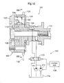
- This valve timing control device 101 includes an outer rotor 102 synchronously rotatable with an unillustrated crankshaft of an engine as an internal combustion engine, and an inner rotor 103 coaxial with the outer rotor 102 and synchronously rotatable with an unillustrated valving opening/closing cam shaft of the engine.
- the outer rotor 102 corresponds to a "driving side rotational member” defined in the present invention
- the inner rotor 103 corresponds to a "drive side rotational member” defined in the present invention.
- the inner rotor 103 is assembled integrally to a leading end portion of an exhausting side cam shaft 111 which constitutes a rotational shaft of a cam for controlling opening/closing of an intake valve or an exhaust valve of the engine.
- This cam shaft 111 is rotatably assembled with an unillustrated cylinder head of the engine.
- the outer rotor 102 is mounted on the outer side of the inner rotor 103 to be rotatable relative thereto within a predetermined range. And, a rear plate 121 to which the cam shaft 111 is connected and a front plate 122 opposite to the side connected to the cam shaft 111 are mounted integrally to the outer rotor 102 and the inner rotor 103. On the outer periphery of the outer rotor 102, a timing sprocket 123 is formed on the outer periphery of the outer rotor 102. Between and across this timing sprocket 123 and an unillustrated gear mounted on the crankshaft of the engine, there is provided an unillustrated force transmitting member 112 such as a timing chain, a timing belt, etc.
- an unillustrated force transmitting member 112 such as a timing chain, a timing belt, etc.
- the outer rotor 102 includes a plurality of projecting portions 124 projecting along the radial direction, with the projecting portions 124 being provided in juxtaposition along the rotational direction. And, between respective adjacent pairs of projecting portions 124 adjacent along the peripheral direction (rotational direction S) of the outer rotor 102, fluid pressure chambers 104 are formed. In the instant embodiment, four fluid pressure chambers 104 are formed.
- vane grooves 131 Along the outer peripheral portion of the inner rotor 103, and at positions opposed to the respective fluid pressure chambers 104, there are formed vane grooves 131. And, vanes 132 are provided to be slidable into the respective vane grooves 131, with each vane 132, as being inserted, partitioning the fluid pressure chamber 104 corresponding thereto into an advanced angle chamber 141 and a retarded angle chamber 142 along the relative rotational direction comprised of directions of arrows S1, S2 in Fig. 13 .
- This vane 132 corresponds to the "partitioning portion" defined in the present invention. As shown in Fig. 12 , this vane 132 is urged to the radially outer side by a spring 133 provided on the inner radial side thereof.
- the advanced angle chamber 141 is communicated with an advanced angle passageway 143 formed in the inner rotor 130 whereas the retarded angle chamber 142 is communicated with a retarded angle passageway 144 formed in the inner rotor 103. As shown in Fig. 12 , the advanced angle passageway 143 and the retarded angle passageway 144 are communicated to a hydraulic circuit 107 to be described later.
- the relative rotational phase between the inner rotor 103 and the outer rotor 102 is displaced to the advance direction S1 or the retardation direction S2 or an urging force is generated for retaining to a desired phase.
- the advance direction S1 is the direction where the displacing direction of the relative position of the vane 132 is the direction denoted by arrow S1 in Fig. 13 .
- the retardation direction S2 is the direction where the displacing direction of the relative position of the vane 132 is the directed denoted by arrow S2 in Fig. 13 .
- the relative rotational phase between the inner rotor 103 and the outer rotor 102 will be referred to simply as “relative rotational phase” hereinafter. Further, this operational oil corresponds to the "fluid”.
- the range within which the relative rotational phase is displaceable is the displaceable range of the vane 132 within the fluid pressure chamber 104 and corresponds to the range between the most retarded phase shown in Fig. 13 and the most advanced phase shown in Fig. 16 .
- a torsion spring 113 is provided between the inner rotor 103 and the front plate 122 fixed to the outer rotor 102. Opposed terminal ends of this torsion spring 113 are retained by unillustrated retaining portions formed in the inner rotor 103 and the front plate 122. And, this torsion spring 113 constantly urges the inner rotor 103 and the outer rotor 102 to the direction of the relative rotational phase being displaced in the advance direction S1.
- phase displacement restricting mechanism 106 for creating a restricting state where the relative rotational phase displacement is restricted within a permissible range and an unrestricting state where the restriction is released.
- the phase displacement restricting mechanism 106 can retain the relative rotational phase within a predetermined range (predetermined phase displacement permissible range).
- the predetermined range is set such that one terminal end thereof constitutes a predetermined locking phase and the other terminal end thereof constitutes an intermediate locking phase.
- the predetermined locking phase is a phase where good engine starting performance can be obtained when engine conditions such as the temperature of the combustion chamber satisfy predetermined conditions.
- this phase is set as the most retarded phase which is the limit phase at which the engine can be started regardless of the temperature of the combustion chamber.
- Fig. 13 corresponds to this most retarded phase.
- the intermediate locking phase is set as such a phase where stable combustion of engine is effected when the temperature of the combustion chamber is low., in order to reduce hydrocarbons (COLD HC) which are produced immediately after the engine startup.
- Fig. 14 corresponds to this intermediate locking phase.
- the phase displacement restricting mechanism 106 includes a restricting recess portion 161 provided in the inner rotor 103.
- the phase displacement restricting mechanism 106 further includes a projecting/retracting member 163 provided in the outer rotor 102.
- This projecting/retracting member 162 can project into or retract from the restricting recess portion 161 and is urged to the side of projecting into the restricting recess portion 161.
- the state wherein the projecting/retracting member 163 projects into the restricting recess portion 161 is the restricting state.
- the state wherein the projecting/retracting member 162 retracts away from the restricting recess portion 161 is the unrestricting state.
- the projecting/retracting member 163 is slidably stored in a storing portion 162 provided in the outer rotor 102 and is urged to the radially inner side by means of an urging spring 164.
- the projecting/retracting member 163, as shown in Fig. 17 is formed concave, with a radially inner small diameter portion 163a, a radially outer large diameter portion 163b and a stepped portion 163c formed between the small diameter portion 163a and the large diameter portion 163b.
- the storing portion 162 stores this projecting/retracting member 163, with allowing projection and retraction of this member 163.
- the storing portion 162 storing the projecting/retracting member 163, with allowing projection and retraction of this member 163, includes a radially inner small diameter portion 162a, a radially outer large diameter portion 162b, and a stepped portion 162c between the small diameter portion 162a and the large diameter portion 162b and is formed to conform to the shape of the projecting/retracting member 163.
- the restricting recess portion 161 is formed with a predetermined depth from the outer peripheral face of the inner rotor 103 such that a portion of the small diameter portion 163a of the projecting/retracting member 163 can enter therein. Also, the recess portion 161 is configured such that even under the restricting state with the projecting/retracting member 163 projecting into the restricting recess portion 161, the relative rotational phase can be displaced within the above-described predetermined range and also operational oil fed from the retarded angle chamber can be charged therein.
- the communication passageway 165 is formed in the inner rotor 103 and establishes communication between the restricting recess portion 161 and the retarded angle chamber 152 and the retarded angle passageway 144. Therefore, when the operational oil is supplied from the hydraulic circuit 107 to the retarded angle chamber 142, a portion of this operational oil is supplied via the communication passageway 161 to the restricting recess portion 161. Therefore, the projecting/retracting member 163 is retracted away from the restricting recess portion 161, thus realizing the unrestricting state.
- the communication passageway 165 which establishes communication between the restricting recess portion 161 of the phase displacement restricting mechanism 106 and the retarded angle chamber 142, incorporates a valving element chamber 109.
- a valving element 192 is mounted within this valving element chamber 109.
- the valving element chamber 109 is formed along the rotational axis of the inner rotor 103 and the outer rotor 102.
- the valving element 192 is mounted so as to project and retract in the direction along the rotational axis of the inner rotor 103 and the outer rotor 102.
- the valving element chamber 109 includes a valving element recess portion 191 as a recess formed on the cylinder. To this valving element recess portion 191, there is communicated a communication passageway 196 for supplying a portion of the operational oil supplied to the advanced angle chamber 141, to an end portion 192e of the valving element 192 which end is to project into the valving element recess portion 191. A portion of the operational oil supplied to the advanced angle chamber 141 is supplied via the communication passageway 196 to the valving element recess portion 191.
- the valving element recess portion 191 allows projection of a portion of the valving element 192 therein and is formed narrow than the valving element chamber 109.
- the valving element 192 is mounted to be slidable along the valving element chamber 109 and the valving element recess portion 191. Further, the valving element 192 can selectively assume a closing state where the member 192 projects into the valving element recess portion 191 and an opening state where the member 192 retracts away from the valving element recess portion 191. Further, the valving element 192 is urged to the direction projecting into the valving element recess portion 191 by means of an urging spring 195.
- the communication passageway 165 includes a hole portion 197 which cutouts away a portion of the retarded angle passageway 144 communicated with the retarded angle chamber 142 and which communicates the retarded angle chamber 142 and the valving element chamber 109 with each other, and further includes a communication passageway 198 for supplying the operational oil discharged from the valving element chamber 109 to the restricting recess portion 161. Therefore, a portion of the operational oil supplied to the retarded angle chamber 142 is supplied to the restricting recess portion 161 via the hole portion 197,the valving element chamber 109 and the communication passageway 198.
- the valving element 192 has a cylindrical shape conforming to the shape of the valving element recess portion 191 and includes a shaft portion 192a, a projecting portion 192b, a wall portion 192c, an outer face portion 192d, an end portion 192e and a wall portion 192f.
- the projecting portion 192b is formed in the outer peripheral face of the shaft portion 192a along the valving element recess portion 191.
- the wall portion 192c is a rising face which is a part of the projecting portion 192b and which is on the projecting side of the valving element 192 projecting into the valving element recess portion 191.
- the outer face portion 129d is the outer peripheral face of the projecting portion 192b.
- the wall portion 192f is a rising face which is a part of the projecting portion 192b and which is on the retracting side of the valving element 192 retracting away from the valving element recess portion 191.
- the wall portion 192c is configured to function as a part of the communication passageway 165 when the valving element 192 is under the opening state. Further, the outer wall 192d is configured to close the hole portion 197.
- the leak passageway L allows leakage of fluid from an intermediate passage r1 to the outside, which intermediate passage r1 is formed in the valving element 22 and comprises a part of the space constituting the communication passageway 165 when the valving element 192 is under the closing state, the intermediate passage (r1) being located between the retarded angle chamber 142 which is a valve timing adjusting chamber communicated with the communication passageway 165 and the valving element 192.
- the operational oil does not fill the communication passageway 165 or the restricting recess portion 161. For this reason, there occurs no erroneous movement of the valving element 192 from the closing state to the opening state, such that it is possible to reliably maintain the restricting state where the projecting/retracting member 163 projects into the restricting recess portion 161.
- the leak passageway L can be formed easily. Further, as the construction of this leak passageway L is simple, the leak passageway L can be formed with high precision, so that a portion of the operational oil supplied to the retarded angle chamber 142 is allowed to leak to the outside in even more reliable manner. Therefore, it is possible to restrict displacement of the relative rotational phase even more reliably.
- the leak passageway L is provided for allowing intentional leak of the operational oil to the outside with higher priority than the leak of a portion of the operational oil supplied to the retarded angle chamber 142 into the communication passageway 165 through the gap between the outer face 192d of the valving element 192 and the hole portion 197. Therefore, the positional relationship between the projecting portion 192b and the hole portion 197 is to be set so as to avoid more than necessary leakage of the operational oil.
- the valving element 192 When the valving element 192 is rendered into the opening state, the space surrounded by the valving element recess portion 191, the shaft portion 192a and the wall portion 192c functions as a part of the communication passageway 165, thus establishing communication between the hole portion 197 and the communication passageway 198, so that the communication passageway 165 is opened up for communication. Therefore, if the operational oil is supplied to the retarded angle chamber 142, this operational oil is supplied to the restricting recess portion 161 via the hole portion 197 and the communication passageway 165. Therefore, in response to the pressure of this supplied operational oil, the projecting/retracting member 163 retracts away from the restricting recess portion 161, so that the phase displacement restricting mechanism 106 can be rendered to the unrestricting state in a reliable manner.
- the wall portion 192c receives the pressure of this operational oil, so that the valving element 192 is urged to the side retracting away from the valving element recess portion 191, thus maintaining the unrestricting state.
- the valving element 192 has a shape as shown in Fig. 19 .
- the shape of this element is not limited thereto, as long as the space between the valving element chamber 109 and the valving element 192 forms a part of the communication passageway 165 and the projecting portion 192b forms the wall portion of the communication passageway 165 and functions, at the same time, to block the communication between the retarded angle chamber 142 and the communication passageway 165.
- the valving element 192 can be formed such that a face including the wall portion 192f constitutes an end face of the valving element 192.
- the positional relationship between the valving element 192 and the hole portion 197 is to be set so as to avoid more than necessary leakage of the operational oil.
- valving element chamber 109, the valving element recess portion 191 and the valving element 192 may be configured to project/retract in the direction normal to the rotational axis of the inner rotor 103 and the outer rotor 102.
- This hydraulic circuit 107 includes a first pump 171, a second pump 172, and a control valve 173.
- the first pump 171 is driven by the engine to feed the operational oil.
- the second pump 172 is driven by a power different from the engine power to feed the operational oil.
- the control valve 173 is a valve for controlling feeding/discharging of operational oil to/from the fluid pressure chambers 104, the locking mechanism 105 and the phase displacement restricting mechanism 106.
- This hydraulic circuit 107 corresponds to what is defined herein as the "fluid feeding/discharging mechanism".
- This hydraulic circuit 107 further includes a control unit 108 for controlling operations of the second pump 172 and the control valve 173.
- the first pump 171 is a mechanical hydraulic pump driven as receiving the drive force of the crankshaft of the engine.
- This fist pump 171 draws in, through an intake port, operational oil reserved in an oil pan 174 and discharges this operational oil through a discharge port to the downstream side.
- the second pump 172 is a pump driven by a power different from the engine power, in this case, this pump 172 is provided as an electrically driven pump driven by an electric motor. Therefore, this second pump 172 can be operated according to operating signals from the control unit 108, regardless of any operational condition of the engine. In operation, this second pump 172 draws in, through an intake port, operational oil reserved in the oil pan 174 and discharges this operational oil through a discharge port to the downstream side.
- the first pump 171 is operated for feeding/discharging operational oil to/from the fluid pressure chambers 104 and the phase displacement restricting mechanism 106.
- the second pump 172 is operated for feeding/discharging operational oil to/from the fluid pressure chambers 104 and the phase displacement restricting mechanism 106.
- the second pump 172 too may be operated to feed the operational oil, as a matter of course.
- cranking operation is initiated to start up the engine.
- the control unit 108 renders the control valve 173 into the retarded angle controlling state, so that the operational oil is fed from the hydraulic circuit 107 to the retarded angle passageway 144.
- the valving element 192 is under the closing state, the communication passageway 165 is blocked, so no operational oil is fed to the restricting recess portion 161. Therefore, the projecting/retracting member 163 maintains its condition of being projected into the restricting recess portion 161 and the phase displacement restricting mechanism 106 is maintained under the restricting state.
- the leak passageway L As the leak passageway L is formed, it is possible to allow a portion of the operational oil to leak to the outside with higher priority than the tendency of the oil portion trying to leak into the communication passageway 165 through the gap between the outer face 192d of the valving element 192 and the hole portion 197. Therefore, the operational oil will not fill the communication passageway 165 or the restricting recess portion 161, so no erroneous operation of the valving element 192 from the closing state to the opening state will occur. Thus, the restricting state of the projecting/retracting member 163 projecting into the restricting recess portion 161 may be maintained reliably.
- the control unit 108 sets the control valve 173 to the advancing control condition, so that the operational oil is supplied from the hydraulic circuit 107 to the advanced angle passageway 143.
- the relative rotational phase is displaced to the advance direction S1 and also the valving element 192 is retracted from the valving element recess portion 191, thus providing the opening state.
- the phase displacement restricting mechanism 106 since the phase displacement restricting mechanism 106 is still maintained under the restricting state, the lateral face of the projecting/retracting member 163 comes into contact with one end face of the restricting recess portion 161, so that the relative rotational phase is restricted to the intermediate locking phase.
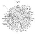
- the control unit 108 renders the control valve 173 to the retardation control condition, so that the operational oil is supplied from the hydraulic circuit 107 to the retarded angle passageway 144. Since the valving element 192 is under the opening state, the operational oil is charged into the restricting recess portion 161 through the communication passageway 165 and as shown in Fig. 15 , the projecting/retracting member 163 is retracted away from the restricting recess portion 163, so that the phase displacement restricting mechanism 106 assumes the unrestricting state. Therefore, it becomes possible to displace the relative rotational phase as desired within the range between the most retarded phase shown in Fig. 13 and the most advanced phase shown in Fig. 16 .
- the operational oil might leak into the communication passageway 165 to fill the restricting recess portion 161 and the resultant pressure may render the valving element 192 into the opening state and cause the projecting/retracting member 163 to retract.
- This leak opening can be provided as a through hole 163d which extends through the restricting recess portion 161 side of the projecting/retracting member 163 and the outer side, as shown in Fig. 21 .
- this can be provided as a through hole 163e adapted for allowing smooth leak of operational oil by increasing the width of the outer side of the through hole 163d.
- the leak opening should not have such a shape that allows more than necessary leak of operational oil when the valving element 192 is under the opening state or interferes with the normal projecting/retracting movement of the projecting/retracting member 163.
- the restricting recess portion 161 is configured to be capable of restricting the relative rotational phase within the predetermined range between the opposed terminal ends defined respectively by the predetermined locking phase and the intermediate locking phase.
- the restricting recess portion 161 may be configured so as to be capable of restricting the relative rotational phase to a predetermined position.
- the valving timing control device 101 of the present invention may employ a locking mechanism which is provided independently of the phase displacement restricting mechanism 106 and which is capable of restricting the relative rotational phase to a predetermined position.
- valve mechanism consisting of the valving element 192 and the valving element chamber 109 is not limited to the one described above, but can be constructed as shown in a modified embodiment to be described next.
- the leak passageway L is formed by providing a cutout portion 193 communicating between the hole portion 197 and the outside in the wall portion of the valving element chamber 109.
- the other arrangements than that relating to the leak passageway L are same as in the foregoing embodiment., therefore, description thereof will be omitted in the following discussion Also, the identical portions or components will be denoted by the identical reference numerals or marks.
- the cutout portion 193 is formed by cutting away a portion of the wall portion of the valving element chamber 109 which portion is adjacent the hole portion 197.
- the cutout portion 193 can be provided in the form of a groove having a fixed width about the valving element chamber 109 or in the form of a recess extending along the perimeter thereof.
- the valving element 192 as shown in Fig. 20 , is formed such that a face thereof including a rising face opposite to the wall portion 192c constitutes the end opposite to the end portion 192e.
- the outer face 192d closes the hole portion 197 and at the same time the opposite end is located as a position partially opening up the cutout portion 193, thus forming the leak passageway L.
- the leak passageway L is opened to the outside through e.g. a clearance provided between the outer rotor 102 and the inner rotor 103.
- the leak passageway L is formed in the valving element 192 and configured to allow leakage of fluid from an intermediate passage (r1) to the outside, the intermediate passage (r1) comprising a space which constitutes a part of the communication passageway 165 when the valving element 192 is under the closing state and which is located between the retarded angle chamber 142 as the valve timing adjusting chamber communicated with the communication passageway 165 and the valving element 192.
- the valving element 192 is under the opening state, the opposite end portion is not overlapped with the hole portion 197, so the leak passageway L is not formed.
- the positional relationship between the valving element 192 and the cutout portion 193, the shape of the cutout portion 193 and the depth of the cutout portion 193 are set so as not to allow more than necessary leakage of the operational oil.
- the leak passageway L is not affected by this movement of the valving element 192. Therefore, a portion of the operational oil fed to the retarded angle chamber 142 can be caused to leak to the outside in a reliable manner. As a result, it is possible to reliably restrict displacement of the relative rotational phase.
- the valving element 192 can have a shape as shown in Fig. 19 .
- the outer face 192d closes the hole portion 197 and the wall portion 192f is located at a position partially opening up the cutout portion 193, thus forming the leak passageway L.
- valve timing control device having a phase displacement restricting mechanism which operates in an advantageous manner.
- one skilled in the art could modify the embodiments of the invention without departing from the essential concept thereof defined in the appended claims. Needless to say, such modified embodiments too are intended to be embraced within the scope defined by the claims.
Landscapes
- Engineering & Computer Science (AREA)
- Mechanical Engineering (AREA)
- General Engineering & Computer Science (AREA)
- Valve Device For Special Equipments (AREA)
- Pile Receivers (AREA)
Abstract
Description
- This application is based on and claims priority under 35 U.S.C. Section 119 to Japanese Patent Application Nos.
2008-132233 2008-179319 - This invention generally relates a valve timing control device.
-
US 7, 363, 898 discloses a valve timing control device configured to start an engine, with a driving side rotational member and a driven side rotational member being interlocked. According toUS 7, 363, 898 , the valve timing control device includes a locking member and an engaging recess portion provided between/across the driving side rotational member and the driven side rotational member. And, when the engine is stopped, a spring member brings the locking member and the engaging recess portion into engagement with each other in response to discharge of operational oil of the valve timing control device. - For enabling this engagement between the locking member and the engaging recess portion, it is required that the driving side rotational member and the driven side rotational member be in alignment with each other at a predetermined position. For this reason, in the case of the valve timing control device disclosed in
US 7, 363, 898 , there is provided a phase displacement restricting mechanism for restricting relative rotation between the locking member and the engaging recess portion within a predetermined angular range, thereby to restrict the relative positions between the locking member and the engagement recess portion within a predetermined range. - This phase displacement restricting mechanism includes an projecting/retracting member ("insertion member") provided in the driven side rotational member and a recess portion provided in the driving side rotational member and capable of retaining the projecting/retracting member. The projecting/retracting member is projected or retracted by operational oil fed into an advanced angle chamber of the valve timing control device, at the time of startup of the engine. In other words, the projecting/retracting member functions to maintain the driving side rotational member and the driven side rotational member under the interlocked state until the operational oil pressure of the valve timing control device builds up at the time of start of the engine. Once the engine has started, the operational oil releases the projecting/retracting member and the locking state by the locking member. With this, the driving side rotational member and the driven side rotational member become rotatable relative to each other and the relative phase between these two rotational members is appropriately controlled through control using the operational oil.
- Incidentally, desirably, the retracting movement of the projecting/retracting member should occur under the state of the operational oil being fed to both the advanced angle chamber and the retarded angle chamber at the time of the engine startup. For, if the projecting/retracting member is retracted to release the interlocked state when the operational oil is not fed to both the advanced angle chamber and the retarded angle chamber, the relative phase between the two rotational members cannot be retained, thus leading to deterioration in the engine startup performance. For this reason, the valve timing control device is provided with a valving element operable by operational oil fed thereto. The projecting/retracting member becomes movable after this valving element is activated.
- However, at the time of stopping the engine, failure, if occurs, in the collaboration between the projecting/retracting member and the valving element could result in impossibility of fixing the driving side rotational member and the driven side rotational member under the interlocked state. For example, at the time of start of engine, by the operational oil fed to the retarded angle chamber, first, the valving element is changed in position to its start position, whereby communication is established between the advanced angle chamber and the projecting/retracting member, so that the oil from the advanced angle chamber causes the projecting/retracting member to be changed in position to the engagement releasing position. When the engine is stopped, these series of collaborative operations are carried out in reverse order. That is, in response to stopping of the engine, the operational oil is drained from the advanced angle chamber and the retarded angle chamber, so that the oil pressure drops. In response to this, first, the projecting/retracting member is moved to the retaining position and then the valving element is moved to its initial position.
- However, due to an unexpected cause, the movement of the valving element may precede the movement of the projecting/retracting member. In this case, the communication between the driving side rotational member and the driven side rotational member will be blocked by the valving element, so that the projecting/retracting member becomes unable to protrude, thus failing to fix the driving side rotational member and the driven side rotational member to the interlocking phase. As a result, the next startup of the engine will become difficult.
- Thus, a need exists for a valve timing control device having a phase displacement restricting mechanism which is not susceptible to the drawback mentioned above.
- According to one aspect of the present invention, there is proposed a valve timing control device comprising:
- a driving side rotational member synchronously rotatable with a crankshaft of an internal combustion engine;
- a driven side rotational member coaxial with said driving side rotational member and synchronously rotatable with a valve opening/closing cam shaft of the internal combustion engine;
- a fluid pressure chamber formed in one of said driving side rotational member and said driven side rotational member;
- a partitioning portion provided in the other of said driving side rotational member and said driven side rotational member for partitioning said fluid pressure chamber into an advanced angle chamber and a retarded angle chamber;
- a fluid feeding/discharging mechanism for feeding/discharging fluid to/from said advanced angle chamber and said retarded angle chamber;
- a phase displacement restricting mechanism for creating a restricting state where relative rotational phase displacement of said driven side rotational member relative to said driving side rotational member is restricted within a permissible range and an unrestricting state where the restriction is released;
- a communication passageway for establishing communication between said phase displacement restricting mechanism and a valve timing adjusting chamber which is one of said advanced angle chamber and said retarded angle chamber;
- a valving element chamber provided in said communication passageway;
- a valving element provided in said valving element chamber, said valving element selectively positioned to a closing state for closing said communication passageway to render said phase displacement restricting mechanism into said restricting state and an opening state for opening up said communication passageway to render said phase displacement restricting mechanism into said unrestricting state; and
- a leak passageway formed in at least one of said valving element and said valving element chamber and configured to allow leakage of fluid from an intermediate passage to the outside when said valving element is under the closing state, said intermediate passage comprising a space which is located between said communicated valve timing adjusting chamber or said phase displacement restricting mechanism and said valving element and which constitutes a portion of said communication passageway.
- With the above construction, even when the valving element is under the closing state, the fluid can leak to the outside through the leak passageway. For instance, when the internal combustion engine is stopped, even if the valving element returns faster than the phase displacement restricting mechanism, any fluid dwelling in the intermediate passage may leak to the outside through the leak passageway. Therefore, the phase displacement restricting mechanism can readily return to the restricting state.
- In the above construction, preferably, said leak passageway is provided in said valving element and configured to allow leak of the fluid to the outside through said intermediate passage between said phase displacement restricting mechanism and said valving element when said phase displacement restricting mechanism is under the unrestricting state and said valving element is under the closing state.
- For instance, when the engine is stopped, even if the valving element returns faster than the phase displacement restricting mechanism, the fluid dwelling in the intermediate passage located between the valving element and the phase displacement restricting mechanism may leak to the outside through the leak passageway. That is to say, even if the phase displacement restricting mechanism is under the unrestricting state and the valving element is under the closing state, the fluid dwelling in the intermediate passage may leak to the outside through the intermediate passage. Therefore, the phase displacement restricting mechanism can readily return to the restricting state.
- Further, preferably, said leak passageway is communicated with said intermediate passage when said valving element is under the closing state, whereas said leak passageway is isolated from said intermediate passage when said valving element is under the opening state.
- According to the above construction, the leak passageway is isolated from the intermediate passage when the valving element is under the opening state. This arrangement can avoid wasteful leakage, thus minimizing loss of the fluid.
- Preferably, said leak passageway comprises a leak through hole provided at an outer peripheral portion of said valving element which is formed as a cylindrical element with one end closed.
- According to the above, by a simple operation of defining the leak through hole in the valving element, there can be provided a phase displacement restricting mechanism which can readily return from the unrestricting state to the restricting state.
- Further preferably, said valving element chamber includes an enlarged diameter portion whose diameter is enlarged to an extent not to contact an outer peripheral portion of the valving element; and when the valving element is under the opening state, the outer peripheral portion of this valving element is in close or gapless contact with the valving element chamber thereby to close the leak through hole; whereas, when the valving element is under the closing state, the leak through holes faces a gap formed between the outer peripheral portion of the valving element and the enlarged diameter portion, thereby to establish communication between the intermediate passage and the outside.
- As the gap is formed between the outer peripheral portion of the valving element and the enlarged diameter portion, even when the valving element is under the closing state, the fluid in the intermediate passage leaks to the outside through this gap and the leak passageway. Therefore, the phase displacement restricting mechanism can readily return from the unrestricting state to the restricting state. In addition, when the valving element is under the opening state, the outer peripheral portion of the valving element comes into close, i.e. gapless, contact with the valving element chamber to close the leak through hole. Thus, loss of fluid can be minimized.
- Further, the valve timing control device further comprises:
- a cutout groove formed in one of an outer peripheral portion of said valving element which is formed as a cylindrical element with one end closed. and said valving element chamber, said cutout groove extending along an operational direction of said valving element;
- a projecting rib formed in the other of the outer peripheral portion of said valving element and said valving element chamber and engageable with said cutout groove for allowing movement of said valving element along the operational direction and also preventing rotation of said valving element relative to said valving element chamber; and
- said leak passageway being formed by a gap between said cutout groove and said projecting rib.
- According to the above, with the simple construction of providing a cutout groove and a projecting rib, there can be provided a phase displacement restricting mechanism which can readily return from the unrestricting state to the restricting state. In addition, since the cutout groove and the projecting rib cooperate as an anti-rotation means against rotation of the valving element. So, it is possible to restrict the possibility of inadvertent leakage of the fluid of the intermediate passage to the outside which would occur if the valving element rotated under the opening state.
- Preferably, the valve timing control device further comprises a projecting portion provided on an outer peripheral face of the valving element, the projecting portion constituting a wall portion of said communication passageway and blocking said communication passageway at the same time; and
wherein said leak passageway is provided between and across said valving element chamber and said valving element so as to allow the fluid to flow to the outside from said valve timing adjusting chamber communicated with said communication passageway when said valving element is under the closing state. - According to the above construction, as the leak passageway is provided between and across the valving element chamber and the valving element, when fluid is supplied into the valve timing adjusting chamber, a portion of this fluid is caused to leak to the outside from the leak passageway, so that the valving element is reliably maintained under the closing state. As a result, the phase displacement restricting mechanism can maintain its restricting state and therefore the displacement in the relative rotational phase can be restricted in a reliable manner. Also, under the opening state, communication is established between the valve timing adjusting chamber and the communication passageway, but no leak passageway is formed. Therefore, even if the fluid is supplied to the valve timing adjusting chamber, the portion of the fluid is not allowed to leak to the outside, but supplied to the phase displacement restricting mechanism. Therefore, the phase displacement restricting mechanism can be rendered to the unrestricting state reliably.
- Preferably, the valve timing control device further comprises a hole portion which is communicated with the valve timing adjusting chamber communicated with the communication passageway;
wherein an outer face of said projecting portion is capable of closing said hole portion; - said leak passageway is formed by configuring said valving element and said valving element chamber such that when the valving element is under the closing state, a portion of said hole portion is displaced from said outer face, thereby to establish communication between said hole portion and the outside.
- By configuring the valving element and the valving element chamber such that a portion of the hole portion is displaced from the outer face, the leak passageway can be formed easily. And, if the construction of the leak passageway is simple as above, then, the leak passageway can be formed with high precision, so it becomes possible to allow a portion of the fluid supplied to the valve timing adjusting chamber to leak to the outside in an even more reliable manner. Therefore, displacement of the relative rotational phase can be restricted even more reliably.
- In case the valve timing control device includes a hole portion provided in a wall portion of the valving element chamber to be communicated with the valve timing adjusting chamber communicated with the communication passageway and the outer face of the projecting portion is capable of closing the hole portion; preferably,
said leak passageway is formed of a cutout portion provided in a wall portion of the valving element chamber for establishing communication between the hole portion and the outside when the valving element is under the closing state. - According to the above construction, the leak passageway is formed by providing a cutout portion in the wall portion of the valving element chamber for establishing communication between the hole portion and the outside. Then, even when the valving element and the valving element chamber are both formed cylindrical to allow rotation of the valving element, the leak passageway can be free from such movement of the valving element.
- The foregoing and additional features and characteristics of the present invention will become more apparent from the following detailed description considered with reference to the accompanying drawings, wherein;
-
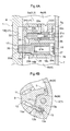
Fig. 1 is a side view in section of a valve timing control device, -
Fig. 2 is a section taken along II-II inFig. 1 , -
Fig. 3 is an enlarged vide showing a communication passageway and a phase displacement restricting mechanism, -
Fig. 4A is a view showing conditions of a valving element and the phase displacement restricting mechanism at the time of engine startup, -
Fig. 4B is a view showing the condition of a locking mechanism at the time of engine startup, -
Fig. 5A is a view showing the conditions of the valving element and the phase displacement restricting mechanism at the time of restriction, -
Fig. 5B is a view showing the condition of the locking mechanism at the time of restriction, -
Fig. 6A is a view showing conditions of the valving element and the phase displacement restricting mechanism at the time of release of restriction, -
Fig. 6B is a view showing the condition of the locking mechanism at the time of release of restriction, -
Fig. 7A is a view showing conditions of the valving element and the phase displacement restricting mechanism at the time of normal operation, -
Fig. 7B is a view showing the condition of the locking mechanism at the time of normal operation, -
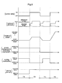
Fig. 8 is a timing chart illustrating control of the valve timing control device, -
Fig. 9 is a view showing the conditions of the valving element and the phase displacement restricting mechanism at the time of engine stop, -
Fig. 10A is a view showing the condition of a valving element of a first modified embodiment at the time of engine stop, -
Fig. 10B is an outer appearance view of the valving element of the first modified embodiment, -
Fig. 11A is a view showing the condition of a valving element of a second modified embodiment at the time of engine stop, -
Fig. 11B is a section view of the valving element of the second modified embodiment, -
Fig. 11C is an outer appearance view of the valving element of the second modified embodiment, -
Fig. 12 is a side view in section showing a valve timing control device according to a second embodiment, -
Fig. 13 is a section taken along XIII-XIII inFig. 12 at the time of most retarded phase, -
Fig. 14 is a section taken along XIII-XIII inFig. 12 at the time of intermediate locking phase, -
Fig. 15 is a section taken along XIII-XIII inFig. 12 at the time of release of the intermediate locking, -
Fig. 16 is a section taken along XIII-XIII inFig. 12 at the time of most advanced phase, -
Fig. 17 is an enlarged view showing the periphery of a phase displacement restricting mechanism and a valving element chamber of the second embodiment, -
Fig. 18A is a section taken along XVIII-XVIII inFig. 17 when the valving element is under the closing state, -
Fig. 18B is a section taken along XVIII-XVIII inFig. 17 when the valving element is under the opening state, -
Fig. 19 is an outer appearance view of the valving element of the second embodiment, -
Fig. 20 is a section taken along XVIII-XVIII in a modified embodiment of the valving element of the second embodiment when the valving element is under the closing state, -
Fig. 21 is an enlarged view showing periphery of an example of the phase displacement restricting mechanism and the valving element chamber when a leak opening is provided in a projecting/retracting member, and -
Fig. 22 is an enlarged view showing periphery of a further example of the phase displacement restricting mechanism and the valving element chamber when a leak opening is provided in a projecting/retracting member, - Next, there will be described, with reference to the accompanying drawings, an embodiment in which a valving timing control device relating to the present invention is applied to an automobile engine as an internal combustion engine.
- As shown in
Fig. 1 andFig. 2 , a valve timing control device A includes anouter rotor 1 synchronously rotatable with an unillustrated crankshaft of an engine as an internal combustion engine, and aninner rotor 3 coaxial with theouter rotor 1 and synchronously rotatable with a valving opening/closing cam shaft C of the engine. Here, theouter rotor 1 corresponds to a "driving side rotational member" defined in the present invention and theinner rotor 3 corresponds to a "drive side rotational member" defined in the present invention. The valve timing control device A includes a plurality offluid pressure chambers 4 formed in theouter rotor 1 and a plurality ofpartitioning portions 5, each partitioningportion 5 partitioning eachfluid pressure chamber 4 into two valve timing adjusting chambers, namely, anadvanced angle chamber 4a and aretarded angle chamber 4b. Thepartitioning portions 5 are provided in theinner rotor 3. Further, the valve timing control device A includes ahydraulic circuit 6 acting as a "fluid feeding/discharging mechanism" for feeding/discharging operational oil as fluid, to/from theadvanced angle chamber 4a and theretarded angle chamber 4b. - As shown in
Fig. 1 , thehydraulic circuit 6 includes a pump P driven by the engine for feeding the operational oil (fluid), and acontrol valve 40 for controlling feeding/discharging of the operational oil to/from thefluid pressure chambers 4. Thehydraulic circuit 6 further includes acontrol unit 41 for controlling operations of the pump P and thecontrol valve 40. The pump P draws in the operational oil reserved in anoil pan 42 and feeds this operational oil to one or both ofadvanced angle passageway 11 andretarded angle passageway 12. - The
inner rotor 3 is assembled integrally to a leading end portion of an exhausting side cam shaft C which constitutes a rotational shaft of an unillustrated cam for controlling opening/closing of an exhaust valve of the engine. This cam shaft C is rotatably assembled with an unillustrated cylinder head of the engine. On the outer side of theinner rotor 3, theouter rotor 1 is mounted. Theouter rotor 1 includes arear plate 7 to which the cam shaft C is connected, afront plate 8 opposite thereto and acylindrical body 2 interconnecting therear plate 7 and thefront plate 8. On the outer periphery of theouter rotor 1, atiming sprocket 9 is formed. Between and across thistiming sprocket 9 and an unillustrated gear mounted on the crankshaft of the engine, there is provided an unillustrated force transmitting member such as a timing chain, a timing belt, etc. - As shown in
Fig. 2 , theouter rotor 1 includes a plurality of projectingportions 10 projecting along the radial direction, with the projectingportions 10 being provided in juxtaposition along the rotational direction. And, between respective adjacent pairs of projectingportions 10 adjacent along the peripheral direction (rotational direction S) of theouter rotor 1, thefluid pressure chambers 4 are formed. In the instant embodiment, fourfluid pressure chambers 4 are formed. Along the outer peripheral portion of theinner rotor 3 opposed to the respectivefluid pressure chambers 4, the plurality ofpartitioning portions 5 are formed along the radial direction, each partitioningmember 5 partitioning eachfluid pressure chamber 4 into theadvanced angle chamber 4a and theretarded angle chamber 4b along the peripheral direction. - As shown in
Fig. 1 andFig. 2 , theinner rotor 3 defines theadvanced angle passageways 11 and the retarded angle passageways 12 along the axial direction of the rotational axis. Eachadvanced angle passageway 11 is communicated with theadvanced angle chamber 4a corresponding thereto and eachretarded angle passageway 12 is communicated with theretarded angle chamber 4b corresponding thereto and also anengaging recess 13a of alocking mechanism 13 to be described later. Theadvanced angle passageways 11 and the retarded angle passageways 14 are connected to thehydraulic circuit 6. Further, theinner rotor 3 forms acommunication groove 14 for establishing communication between aretarded angle chamber 4b located adjacent thelocking mechanism 13 and the engagingrecess 13 defined in thislocking mechanism 13. - In operation, as the operational oil as fluid is supplied to or discharged from one or both of the
advanced angle chamber 4a and theretarded angle chamber 4b, the relative rotational phase of theinner rotor 3 relative to theouter rotor 1 is displaced. InFig. 2 , the direction denoted with arrow S1 is the advanced angle direction S1 and the direction denoted with arrow S2 is the retarded angle direction S2. Incidentally, the relatively rotatable range over which the relative rotational phase is displaceable is the range between the most retarded phase where thepartitioning portion 5 is displaced maximally toward the retarded angle direction S2 within thefluid pressure chamber 4 and the most advanced phase where thepartitioning portion 5 is displaced maximally toward the advanced angle direction S1 within thefluid pressure chamber 4.Fig. 2 shows the condition of the most advanced phase. - The
member 15 shown inFig. 1 is atorsion spring 15 provided between theinner rotor 3 and thefront plate 8 affixed to theouter rotor 1. Thistorsion spring 15 constantly urges theinner rotor 3 and theouter rotor 1 in the direction of the relative rotational phase being displaced in the advanced angle direction S1. - As shown in
Fig. 2 , between theouter rotor 1 and theinner rotor 3, there is provided thelocking mechanism 13 capable of restricting the relative rotational phase therebetween within a predetermined locking phase. Thislocking mechanism 13 includes a slidinggroove 13b, a lockingmember 13c slidable along the slidinggroove 13b, and an urgingspring 13d for urging the lockingmember 13c toward the engagingrecess 13a. The slidinggroove 13b is provided in one 10a of the plurality of projectingportions 10 of theouter rotor 1, which one is formed wider than the others. The engagingrecess 13a is provided in theinner rotor 3 such that the radially inner end of the lockingmember 13c is engageable therewith when the relative rotational phase is at the predetermined locking phase. Therefore, the urgingspring 13d urges the lockingmember 13c toward the inner radial side. - When the relative rotational phase is at the predetermined locking phase, under the urging force of the urging
spring 13d, the lockingmember 13c projects into the engagingrecess 13a to be engaged therein. Hence, thelocking mechanism 13 is rendered into the locking condition thereby to restrict the relative rotational phase to the predetermined locking phase. Incidentally, as this embodiment relates to a valve timing control mechanism for the exhaust side, the predetermined locking phase is the most retarded phase. When the relative rotational phase is the predetermined locking phase, when the operational oil from thehydraulic circuit 6 is fed through theretarded angle passageway 12 into the engagingrecess 13a, the lockingmember 13c is retracted away from the engagingrecess 13a. This provides the lock released state which allows displacement in the relative rotational phase between theinner rotor 3 and theouter rotor 1. - As shown in
Figs. 4A through 7B andFig. 9 , between theouter rotor 1 and theinner rotor 3, there is provided a phasedisplacement restricting mechanism 17 for creating a restricting state where the relative rotational phase displacement is restricted within a predetermined permissible range and an unrestricting state where the restriction is released. This predetermined phase displacement permissible range can be set to a predetermined range including the predetermined locking phase to facilitate the engagement of the lockingmember 13c relative to theengaging recess 13a at the time of stopping the engine. - The phase
displacement restricting mechanism 17 includes a storingportion 18, a restrictingrecess portion 19, and a projecting/retractingmember 20. The storingportion 18 is formed in thewide partitioning portion 5a of the plurality ofpartitioning portions 5 along the axial direction. The restrictingrecess portion 19 is formed in thefront plate 8 of theouter rotor 1. The projecting/retractingmember 20 is slidably stored within the storingportion 18, so that the projecting/retractingmember 20 can project/retract from/into the storingportion 18. When the leading end of the projecting/retractingmember 20 projects from the storingportion 18 and is inserted into the restrictingrecess portion 19, there is realized a restricting state. Whereas, when the leading end of the projecting/retractingmember 20 retracts into the storingportion 18 away from the restrictingrecess portion 19, there is realized an unrestricting state. The projecting/retractingmember 20 is urged to be inserted into the restrictingrecess portion 19 by an urgingspring 27. - The projecting/retracting
member 20 includes asmall diameter portion 20a formed on the side of the leading end adjacent thefront plate 8 and alarge diameter portion 20c on the side of the base end adjacent therear plate 7. Between thesmall diameter portion 20a and thelarge diameter portion 20c, a steppedportion 20b is formed. The storingportion 18 includes asmall diameter portion 18a on the side of the leading end and alarge diameter portion 18c on the side of the base end. Between thesmall diameter portion 18a and thelarge diameter portion 18c, a steppedportion 18b is formed. Therefore, as shown inFig. 4A , andFig. 5A , when there is provided the restricting state in response to the projection of the projecting/retractingmember 20 by the urgingspring 27, the steppedportion 20b of the projecting/retractingmember 20 comes into engagement with the steppedportion 18b of the storingportion 18, thus preventing the leading end of the projecting/retractingmember 20 from coming into contact with the bottom face of the restrictingrecess portion 19. Thelarge diameter portion 18c is communicated with the outside through a leak throughhole 7b formed in therear plate 7. - The restricting
recess portion 19 has a depth designed to allow insertion of the leading end of the projecting/retractingmember 20 and also has a length along the rotational direction corresponding to the predetermined phase displacement permissible range as shown inFig. 3 . With these arrangements, under the restricting state with the projecting/retractingmember 20 being inserted into the restrictingrecess portion 19, the relative rotational phase can be displaced within the predetermined phase displacement permissible range. Incidentally, if the displacement of the relative rotational phase exceeds the predetermined phase displacement permissible range, the projecting/retractingmember 20 comes into contact with the lateral face of the restrictingrecess portion 19, whereby any further displacement is prevented. - In midway of a communication passageway communicating (r) which establishes communication between the phase
displacement restricting mechanism 17 and theadvanced angle chamber 4a, there is provided avalving element chamber 21. In thisvalving element chamber 21, avalving element 22 is mounted so as to selectively provide a closing state for closing the communicating passageway (r) and an opening state for opening up the communication passageway (r). More particularly, the closing state is a state wherein the communication passageway (r) is closed to render the phasedisplacement restricting mechanism 17 into the restricting state. The opening state is a state wherein the communication passageway (r) is opened up and the operational oil is fed into theadvanced angle chamber 4a, thereby to render the phasedisplacement restricting mechanism 17 into the unrestricting state. - The
valving element 22 is slidably stored within thevalving element chamber 21 and includes asmall diameter portion 22a on the side of the leading end alarge diameter portion 22c on the side of the base end, thevalving element 22 being formed like a cylinder with a closed end. Between thesmall diameter portion 22a and thelarge diameter portion 22c, a steppedportion 22b is formed. Thevalving element chamber 21 is formed in thewide partitioning portion 5a of the plurality of thepartitioning portions 5, in juxtaposition with the storingportion 18 of the phasedisplacement restricting mechanism 17. Further, between thevalving element chamber 21 includes, between thesmall diameter portion 21a and thelarge diameter portion 21c, anenlarged diameter portion 21b whose diameter is enlarged to an extent not to contact an outer peripheral portion of thevalving element 22. Thevalving element 22 is urged to the side of the leading end by an urgingspring 28. Thelarge diameter portion 21c is communicated with the outside through a leak throughhole 7a formed in therear plate 7. - The
wide partitioning portion 5a forms afirst passageway 23 capable of establishing communication between thelarge diameter portion 21c and theadvanced angle chamber 4a, asecond communication passageway 24 capable of establishing communication between theenlarged diameter portion 21b and the restrictingrecess portion 19, athird communication passageway 25 capable of establishing communication between thesmall diameter portion 21a and theretarded angle chamber 4b, and afourth communication passageway 26 capable of establishing communication between thelarge diameter portion 18c and theretarded angle chamber 4b. Thefirst communication passageway 23, thevalving element chamber 21, thesecond communication passageway 24 and the restrictingrecess portion 19 together constitute the communication passageway (r) for establishing communication between the phasedisplacement restricting mechanism 17 and theadvanced angle chamber 4a. - When the
valving element 22 is moved to the leading end side by the urgingspring 28, as shown inFig. 4A , there is realized the closing state
wherein thelarge diameter portion 22c closes thefirst passageway 23 and thevalving element 22 closes the communication passageway (r). Under this state, even if operational oil from thehydraulic circuit 6 is supplied to thefirst passageway 23 via theadvanced angle chamber 4a, the phasedisplacement restricting mechanism 17 maintains the restricting state since thefirst passageway 23 is closed. - When the
valving element 22 is moved to the base end side, in response to feeding of operational oil from thehydraulic circuit 6 to the leading end of thesmall diameter portion 21a of thevalving element chamber 21 via theretarded angle chamber 4b and thethird passageway 25, as shown inFig. 5A ,Fig. 6A andFig. 7A , a gap is formed between thevalving element 22 and thevalving element chamber 21, thereby to establish communication between thefirst passageway 23 and thesecond passageway 24, so that the there is realized the opening state wherein thevalving element 22 opens up the communication passageway (r). In this, if the operational oil from thehydraulic circuit 6 is supplied to the restrictingrecess 19 via theadvanced angle chamber 4a, thefirst passageway 23, thevalving element chamber 21 and thesecond passageway 24, the projecting/retractingelement 20 is retracted to render the phasedisplacement restricting mechanism 17 into the releasing state. - In the
valving element 22, there is provided a leak throughhole 22d as a "leak passageway" configured to allow leakage of fluid from an intermediate passage (r1) to the outside, the intermediate passage (r1) comprising a space which is located between thevalving element 22 and the phasedisplacement restricting mechanism 17 and constituting a portion of the communication passageway (r). As shown inFig. 4A etc., the leak throughhole 22d is provided at thelarge diameter portion 22c of thevalving element 22. In operation, even when thevalving element 22 is under the closing state, the operational oil is allowed to leak to the outside from the intermediate passage (r1) through the leak throughhole 22d. - As shown in
Fig. 5A ,6A ,7A , etc., when thevalving element 22 is under the opening condition, thelarge diameter portion 22c of thisvalving element 22 is in gapless contact with theenlarged diameter portion 21b of thevalving element chamber 21, thereby to close the leak throughhole 22d. On the other hand, as shown inFig. 4A , when thevalving element 22 is under the closing state, a gap is formed between thelarge diameter portion 22c of thisvalving element 22 and theenlarged diameter portion 21b of thevalving element chamber 21. That is, the leak throughhole 22d is opened up to establish communication between thesecond passageway 24 and the outside. - For example, when the engine is stopped, even if the
valving element 22 is rendered into the closing state faster, with the phasedisplacement restricting mechanism 17 being under the releasing state, since the leak throughhole 22d is opened, communication is established between thesecond passageway 24 and the outside. As shown inFig. 9 , the operational oil present in the restrictingrecess portion 19 and thesecond passageway 24 will flow through the leak throughhole 22d and the inside of thevalving element 22 to the outside from the leak throughhole 7a of therear plate 7. In association with this leak of the operational oil of the restrictingrecess portion 19 and thesecond passageway 24, the projecting/retractingmember 20 is inserted into the restrictingrecess portion 19, whereby the phasedisplacement restricting mechanism 17 can readily return from the releasing state to the restricting state. - If the leak passageway is formed as the leak through
hole 22d provided in the outer peripheral portion of thevalving element 22 as described above, the construction which allows facilitated return of the phase displacement restricting mechanism from the releasing state to the restricting state can be constructed by the simple arrangement of only defining the leak through hole in the valving element. - Further, as the gap is formed between the outer peripheral portion of the
valving element 22 and theenlarged diameter portion 21b of thevalving element chamber 21, even when thevalving element 22 is under the closing state, the operational oil of the intermediate passage (r1) leaks to the outside through this gap and the leak passageway. Hence, there can be obtained the construction which allows facilitated return of the phase displacement restricting mechanism from the releasing state to the restricting state. In addition, when thevalving element 22 is under the opening state, the outer peripheral portion of thevalving element 22 is placed in gapless contact with thevalving element chamber 22,thereby to close the leak throughhole 22d. As a result, excessive leak of operational oil can be restricted and waste of operational oil can be minimized. - Next, the operations of the valve timing control device will be described with reference to
Figs. 4A through 8 . When the engine is started, as shown inFig. 4A , the phasedisplacement restricting mechanism 17 is under the restricting state and thevalving element 22 is under the closing state. Further, thelocking mechanism 13 is under the locking state as shown in Fig. 14B. Under this condition, the relative rotational phase is restricted to the predetermined locking phase. For starting the engine, as indicated by the period T1 inFig. 8 and shown inFig. 4A , first, operational oil is supplied to theadvanced angle chamber 4a. - Next, as shown by the period T2 in
Fig. 8 , when the operational oil is supplied to theretarded angle chamber 4b, as shown inFig.5B , thelocking mechanism 13 is rendered into the locking releasing state, and also as shown inFig. 5A , thevalving element 22 is rendered into the opening condition. As shown by the period T2 isFig. 8 , under the above condition, the supply of the operational oil to theadvanced angle chamber 4a is temporarily stopped. Therefore, the phasedisplacement restricting mechanism 17 maintains the restricting state, so that displacement of the relative rotational phase is restricted within the predetermined phase displacement permissible range. - Subsequently, as shown by the period T3 in
Fig. 8 , when the operational oil is supplied to theadvanced angle chamber 4a, the restriction of the relative rotational phase is released as shown inFig. 6A . With this, as shown inFig. 6B , the relative rotational phase is returned slightly to the set locking phase, and thelocking mechanism 13 is rendered into the locking state again. - During the normal operation of the engine after the period T4 in
Fig. 8 , the operational oil is supplied to theadvanced angle chamber 4a and theretarded angle chamber 4b. So, as shown inFig. 7A , the restricting state of the phasedisplacement restricting mechanism 17 is released, and as shown inFig. 7B , thelocking mechanism 13 is rendered into the lock releasing state. By controlling the supply of the operational oil to theadvanced angle chamber 4a and theretarded angle chamber 4b, the relative rotational phase can be displaced from the most retarded phase to the most advanced phase and the opening/closing timing of the valve can be varied according to the operational condition. - The valve mechanism consisting essentially of the
valving element 22 and thevalving element chamber 21 is not limited to the construction described above, but can be modified as described in a first modified embodiment as follows. - As shown in
Fig. 10B , in the base end sidelarge diameter portion 22c of thevalving element 22, there is provided acutout groove 31 along the moving direction (longitudinal direction in the figure) of thevalving element 22. On the other hand, in thevalving element chamber 21, there is provided a projectingrib 32 which comes into engagement with thecutout groove 31 to allow movement of thevalving element 22 along its moving direction and which prevents rotation of thevalving element 22 relative to thevalving element chamber 21 at the same time. Agap 33 formed between thecutout groove 31 and the projectingrib 32 constitutes a "leak passageway". - More particularly, of the
cutout groove 31, its baseend side groove 31a is formed deeper than its leadingend side groove 31b. When thevalving element 22 is under the closing state, as shown inFig. 10A , thegap 33 forms a bent passageway. When thevalving element 22 is under the opening state, the bottom face of the leadingend side groove 31b and the leading end face of the projectingrib 32 are in adjacent opposition to each other, thereby to close thegap 33. - The valve mechanism consisting essentially of the
valving element 22 and thevalving element chamber 21 is not limited to the constructions described above, but can be further modified as described in a second modified embodiment as follows. - As shown in
Fig. 11A and Fig. 11B , thevalving element chamber 21 is provided with acutout groove 34 along the operational direction (longitudinal direction in the figures) of thevalving element 22. As shown inFigs. 11A through 11C , in the outer peripheral portion of thevalving element 22, there is provided a projectingrib 35 which comes into engagement with thecutout groove 34 to allow movement of thevalving element 22 along its moving direction and which prevents rotation of thevalving element 22 relative to thevalving element chamber 21 at the same time. A gap formed between thecutout groove 34 and the projectingrib 35 constitutes a "leak passageway". - More particularly, in the lateral face of the projecting
rib 35, aleak groove 35a is formed as a gap. As shown inFig. 11A and Fig. 11C , theleak groove 35a is formed in the base end side large diameter portion 33c of thevalving element 22 in such a manner than the leading end of the groove is located at a position not reaching the steppedportion 22b. When thevalving element 22 is under the closing state, the projectingrib 35 projects from thecutout groove 34 and the leading end of theleak groove 35a is exposed. When thevalving element 22 is under the opening state, the projectingrib 35 is retracted into thecutout groove 34. With this, as theleak groove 35a, including its leading end on the side of the steppedportion 22b, is hidden within thegroove 34, so the leak passageway is closed. - In the first modified embodiment and the second modified embodiment described above, the
cutout groove 34 along the operational direction of thevalving element 22 is provided in one of the outer peripheral portion of thevalving element 21 and thevalving element chamber 21 and the projectingrib cutout groove 34 for allowing movement of thevalving element 22 along its operational direction and preventing rotation of thevalving element 22 relative to thevalving element chamber 22 at the same time is provided in the other of the outer peripheral portion of thevalving element 21 and thevalving element chamber 21. And, the leak passageway is provided as the gap formed between thecutout groove 34 and the projectingrib - Namely, by the simple arrangement of providing the
cutout groove 34 and the projectingrib displacement restricting mechanism 17 from the releasing state to the restricting state. In addition, since thecutout groove 34 and the projectingrib valving element 22, it is possible to restrict leakage of the operational oil of the intermediate passage r1 which would occur if thevalving element 22 rotated while thevalving element 22 is under the opening state. - The valving timing control device of the present invention is not limited to the above constructions, but can be modified in various ways as follows.
- (1) In the foregoing discussion, the
inner rotor 3 is integrally assembled with the leading end of the exhaust side cam shaft C constituting a rotational shaft of the cam controlling opening/closing of the exhaust valve of the engine. Instead of this, theinner rotor 3 may be integrally assembled with the leading end of the intake side cam shaft C constituting a rotational shaft of the cam controlling opening/closing of the intake valve of the engine. - (2) In the foregoing discussion, there was described the construction comprising the
fluid pressure chambers 4 formed in the driving side rotational member and thepartitioning members 5 provided in the driven side rotational member for partitioning each fluid pressure chamber into theadvanced angle chamber 4a and theretarded angle chamber 4b. Alternatively, the construction can comprise thefluid pressure chambers 4 provided in the driven side rotational member and thepartitioning members 5 provided in the driving side rotational member for partitioning each fluid pressure chamber into theadvanced angle chamber 4a and theretarded angle chamber 4b. - (3) In the foregoing discussion, the
partitioning portions 5 are provided at the portions in the outer peripheral portion of theinner rotor 3 facing the respectivefluid pressure chambers 4. However, the invention is not limited thereto. Instead, grooves can be formed in the outer peripheral portion of theinner rotor 3 at positions opposed to the respectivefluid pressure chambers 4, and plate-like members being fitted therein, to constitute the partitioning members. - (4) In the foregoing discussion, the communication passageway (r) establishes communication between the phase
displacement restricting mechanism 17 and theadvanced angle chamber 4a. The invention is not limited thereto. The communication passageway (r) can be modified to establish communication between the phasedisplacement restricting mechanism 17 and theretarded angle chamber 4b. - Next, there will be described, with reference to the accompanying drawings, a further embodiment in which a valving timing control device relating to the present invention is applied to an automobile engine as an internal combustion engine.
- This valve
timing control device 101 includes anouter rotor 102 synchronously rotatable with an unillustrated crankshaft of an engine as an internal combustion engine, and aninner rotor 103 coaxial with theouter rotor 102 and synchronously rotatable with an unillustrated valving opening/closing cam shaft of the engine. Here, theouter rotor 102 corresponds to a "driving side rotational member" defined in the present invention and theinner rotor 103 corresponds to a "drive side rotational member" defined in the present invention. - The
inner rotor 103 is assembled integrally to a leading end portion of an exhaustingside cam shaft 111 which constitutes a rotational shaft of a cam for controlling opening/closing of an intake valve or an exhaust valve of the engine. Thiscam shaft 111 is rotatably assembled with an unillustrated cylinder head of the engine. - The
outer rotor 102 is mounted on the outer side of theinner rotor 103 to be rotatable relative thereto within a predetermined range. And, arear plate 121 to which thecam shaft 111 is connected and afront plate 122 opposite to the side connected to thecam shaft 111 are mounted integrally to theouter rotor 102 and theinner rotor 103. On the outer periphery of theouter rotor 102, atiming sprocket 123 is formed. Between and across thistiming sprocket 123 and an unillustrated gear mounted on the crankshaft of the engine, there is provided an unillustratedforce transmitting member 112 such as a timing chain, a timing belt, etc. - In operation, when the crankshaft of the engine is driven to rotate, this rotational force is transmitted via the
force transmitting member 112 to thetiming sprocket 123, whereby theouter rotor 102 is driven to rotate along a rotational direction S shown inFig. 13 . In association with this rotational drive of theouter rotor 102, theinner rotor 103 is driven to rotate along the rotational direction S shown inFig. 13 and thecam shaft 111 is rotated. Then, the cam mounted on thecam shaft 111 pushes down the intake value or the exhaust vale of the engine thereby to open this valve. - As shown in
Fig. 13 , theouter rotor 102 includes a plurality of projectingportions 124 projecting along the radial direction, with the projectingportions 124 being provided in juxtaposition along the rotational direction. And, between respective adjacent pairs of projectingportions 124 adjacent along the peripheral direction (rotational direction S) of theouter rotor 102,fluid pressure chambers 104 are formed. In the instant embodiment, fourfluid pressure chambers 104 are formed. - Along the outer peripheral portion of the
inner rotor 103, and at positions opposed to the respectivefluid pressure chambers 104, there are formedvane grooves 131. And,vanes 132 are provided to be slidable into therespective vane grooves 131, with eachvane 132, as being inserted, partitioning thefluid pressure chamber 104 corresponding thereto into anadvanced angle chamber 141 and aretarded angle chamber 142 along the relative rotational direction comprised of directions of arrows S1, S2 inFig. 13 . Thisvane 132 corresponds to the "partitioning portion" defined in the present invention. As shown inFig. 12 , thisvane 132 is urged to the radially outer side by aspring 133 provided on the inner radial side thereof. - The
advanced angle chamber 141 is communicated with anadvanced angle passageway 143 formed in the inner rotor 130 whereas theretarded angle chamber 142 is communicated with aretarded angle passageway 144 formed in theinner rotor 103. As shown inFig. 12 , theadvanced angle passageway 143 and theretarded angle passageway 144 are communicated to ahydraulic circuit 107 to be described later. - As the operational oil from the
hydraulic circuit 107 is supplied to one or both of theadvanced angle chamber 141 and theretarded angle chamber 142, the relative rotational phase between theinner rotor 103 and theouter rotor 102 is displaced to the advance direction S1 or the retardation direction S2 or an urging force is generated for retaining to a desired phase. Here, the advance direction S1 is the direction where the displacing direction of the relative position of thevane 132 is the direction denoted by arrow S1 inFig. 13 . Also, the retardation direction S2 is the direction where the displacing direction of the relative position of thevane 132 is the directed denoted by arrow S2 inFig. 13 . Unless mentioned otherwise explicitly, the relative rotational phase between theinner rotor 103 and theouter rotor 102 will be referred to simply as "relative rotational phase" hereinafter. Further, this operational oil corresponds to the "fluid". The range within which the relative rotational phase is displaceable is the displaceable range of thevane 132 within thefluid pressure chamber 104 and corresponds to the range between the most retarded phase shown inFig. 13 and the most advanced phase shown inFig. 16 . - As shown in
Fig. 12 , between theinner rotor 103 and thefront plate 122 fixed to theouter rotor 102, atorsion spring 113 is provided. Opposed terminal ends of thistorsion spring 113 are retained by unillustrated retaining portions formed in theinner rotor 103 and thefront plate 122. And, thistorsion spring 113 constantly urges theinner rotor 103 and theouter rotor 102 to the direction of the relative rotational phase being displaced in the advance direction S1. - Between the
outer rotor 102 and theinner rotor 103, there is provided a phasedisplacement restricting mechanism 106 for creating a restricting state where the relative rotational phase displacement is restricted within a permissible range and an unrestricting state where the restriction is released. The phasedisplacement restricting mechanism 106 can retain the relative rotational phase within a predetermined range (predetermined phase displacement permissible range). In this embodiment, the predetermined range is set such that one terminal end thereof constitutes a predetermined locking phase and the other terminal end thereof constitutes an intermediate locking phase. - The predetermined locking phase is a phase where good engine starting performance can be obtained when engine conditions such as the temperature of the combustion chamber satisfy predetermined conditions. Here, this phase is set as the most retarded phase which is the limit phase at which the engine can be started regardless of the temperature of the combustion chamber.
Fig. 13 corresponds to this most retarded phase. The intermediate locking phase is set as such a phase where stable combustion of engine is effected when the temperature of the combustion chamber is low., in order to reduce hydrocarbons (COLD HC) which are produced immediately after the engine startup.Fig. 14 corresponds to this intermediate locking phase. - The phase
displacement restricting mechanism 106 includes a restrictingrecess portion 161 provided in theinner rotor 103. The phasedisplacement restricting mechanism 106 further includes a projecting/retractingmember 163 provided in theouter rotor 102. This projecting/retractingmember 162 can project into or retract from the restrictingrecess portion 161 and is urged to the side of projecting into the restrictingrecess portion 161. The state wherein the projecting/retractingmember 163 projects into the restrictingrecess portion 161 is the restricting state. The state wherein the projecting/retractingmember 162 retracts away from the restrictingrecess portion 161 is the unrestricting state. The projecting/retractingmember 163 is slidably stored in a storingportion 162 provided in theouter rotor 102 and is urged to the radially inner side by means of an urgingspring 164. - The projecting/retracting
member 163, as shown inFig. 17 , is formed concave, with a radially innersmall diameter portion 163a, a radially outerlarge diameter portion 163b and a steppedportion 163c formed between thesmall diameter portion 163a and thelarge diameter portion 163b. The storingportion 162 stores this projecting/retractingmember 163, with allowing projection and retraction of thismember 163. The storingportion 162 storing the projecting/retractingmember 163, with allowing projection and retraction of thismember 163, includes a radially innersmall diameter portion 162a, a radially outerlarge diameter portion 162b, and a steppedportion 162c between thesmall diameter portion 162a and thelarge diameter portion 162b and is formed to conform to the shape of the projecting/retractingmember 163. - The restricting
recess portion 161 is formed with a predetermined depth from the outer peripheral face of theinner rotor 103 such that a portion of thesmall diameter portion 163a of the projecting/retractingmember 163 can enter therein. Also, therecess portion 161 is configured such that even under the restricting state with the projecting/retractingmember 163 projecting into the restrictingrecess portion 161, the relative rotational phase can be displaced within the above-described predetermined range and also operational oil fed from the retarded angle chamber can be charged therein. Under the restricting state, the opposed lateral faces of thesmall diameter portion 163a of the projecting/retractingmember 163 come into contact with the oneend face 161a or theother end face 161b of the restrictingrecess portion 161, thereby to restrict displacement of the relative rotational phase. - The
communication passageway 165, as shown inFig. 17 ,Fig. 18A and Fig. 18B , is formed in theinner rotor 103 and establishes communication between the restrictingrecess portion 161 and the retarded angle chamber 152 and theretarded angle passageway 144. Therefore, when the operational oil is supplied from thehydraulic circuit 107 to theretarded angle chamber 142, a portion of this operational oil is supplied via thecommunication passageway 161 to the restrictingrecess portion 161. Therefore, the projecting/retractingmember 163 is retracted away from the restrictingrecess portion 161, thus realizing the unrestricting state. - That is to say, when the operational oil is charged into the restricting
recess portion 161 and in response to the pressure of this operational oil, the force urging the projecting/retractingmember 163 to the radially outer side exceeds the urging force of the urgingspring 164, then, as shown inFig. 15 , the projecting/retractingmember 163 is retracted away from the restrictingrecess portion 161, thus realizing the unrestricting sate which allows the displacement of the relative rotational phase to exceed the predetermined range. On the other hand, when the operational oil is discharged from the restrictingrecess portion 161, due to the urging force of the urgingspring 164, the projecting/retractingmember 163 projects into the restrictingrecess portion 161, thus realizing the restricting state. - As shown in
Fig. 17 ,Fig. 18A and Fig. 18B , thecommunication passageway 165 which establishes communication between the restrictingrecess portion 161 of the phasedisplacement restricting mechanism 106 and theretarded angle chamber 142, incorporates avalving element chamber 109. Within thisvalving element chamber 109, avalving element 192 is mounted. Thevalving element chamber 109 is formed along the rotational axis of theinner rotor 103 and theouter rotor 102. Thevalving element 192 is mounted so as to project and retract in the direction along the rotational axis of theinner rotor 103 and theouter rotor 102. - The
valving element chamber 109 includes a valvingelement recess portion 191 as a recess formed on the cylinder. To this valvingelement recess portion 191, there is communicated acommunication passageway 196 for supplying a portion of the operational oil supplied to theadvanced angle chamber 141, to anend portion 192e of thevalving element 192 which end is to project into the valvingelement recess portion 191. A portion of the operational oil supplied to theadvanced angle chamber 141 is supplied via thecommunication passageway 196 to the valvingelement recess portion 191. The valvingelement recess portion 191 allows projection of a portion of thevalving element 192 therein and is formed narrow than thevalving element chamber 109. - The
valving element 192 is mounted to be slidable along thevalving element chamber 109 and the valvingelement recess portion 191. Further, thevalving element 192 can selectively assume a closing state where themember 192 projects into the valvingelement recess portion 191 and an opening state where themember 192 retracts away from the valvingelement recess portion 191. Further, thevalving element 192 is urged to the direction projecting into the valvingelement recess portion 191 by means of an urgingspring 195. - The
communication passageway 165 includes ahole portion 197 which cutouts away a portion of theretarded angle passageway 144 communicated with theretarded angle chamber 142 and which communicates theretarded angle chamber 142 and thevalving element chamber 109 with each other, and further includes acommunication passageway 198 for supplying the operational oil discharged from thevalving element chamber 109 to the restrictingrecess portion 161. Therefore, a portion of the operational oil supplied to theretarded angle chamber 142 is supplied to the restrictingrecess portion 161 via thehole portion 197,thevalving element chamber 109 and thecommunication passageway 198. - The
valving element 192, as shown inFig. 19 , has a cylindrical shape conforming to the shape of the valvingelement recess portion 191 and includes ashaft portion 192a, a projectingportion 192b, awall portion 192c, anouter face portion 192d, anend portion 192e and awall portion 192f. The projectingportion 192b is formed in the outer peripheral face of theshaft portion 192a along the valvingelement recess portion 191. Thewall portion 192c is a rising face which is a part of the projectingportion 192b and which is on the projecting side of thevalving element 192 projecting into the valvingelement recess portion 191. The outer face portion 129d is the outer peripheral face of the projectingportion 192b. Thewall portion 192f is a rising face which is a part of the projectingportion 192b and which is on the retracting side of thevalving element 192 retracting away from the valvingelement recess portion 191. - The
wall portion 192c is configured to function as a part of thecommunication passageway 165 when thevalving element 192 is under the opening state. Further, theouter wall 192d is configured to close thehole portion 197. - When the
valving element 192 is under the closing state, theouter face 192d closes thehole portion 197 and thewall portion 192f is located at a position partially opening up thehole portion 197, thus forming a leak passageway L. This leak passageway L is opened to the outside via e.g. a clearance provided between theouter rotor 102 and theinner rotor 103. The leak passageway L allows leakage of fluid from an intermediate passage r1 to the outside, which intermediate passage r1 is formed in thevalving element 22 and comprises a part of the space constituting thecommunication passageway 165 when thevalving element 192 is under the closing state, the intermediate passage (r1) being located between theretarded angle chamber 142 which is a valve timing adjusting chamber communicated with thecommunication passageway 165 and thevalving element 192. - As shown in
Fig. 18A , under the closing state where thevalving element 22 projects into the valvingelement recess portion 191, thehole portion 197 is closed by theouter face 192d. Hence, even if the operational oil is supplied to theretarded angle chamber 142, supply of the operational oil from theretarded angle chamber 142 to thevalving element chamber 109 can be prevented. In this, as the leak passageway L is formed, so, even if a part of the operational oil supplied to theretarded angle chamber 142 attempts to leak into thecommunication passageway 165 through the gap between theouter face 192d of thevalving element 192 and thehole portion 197, the operational oil can be intentionally caused to leak to the outside, in priority thereto. Therefore, the operational oil does not fill thecommunication passageway 165 or the restrictingrecess portion 161. For this reason, there occurs no erroneous movement of thevalving element 192 from the closing state to the opening state, such that it is possible to reliably maintain the restricting state where the projecting/retractingmember 163 projects into the restrictingrecess portion 161. - As described above, since the
valving element 192 and thevalving element chamber 109 are configured such that under the closing state, a portion of thehole portion 197 is displaced from the outer face 197d, thus forming the leak passageway L, the leak passageway L can be formed easily. Further, as the construction of this leak passageway L is simple, the leak passageway L can be formed with high precision, so that a portion of the operational oil supplied to theretarded angle chamber 142 is allowed to leak to the outside in even more reliable manner. Therefore, it is possible to restrict displacement of the relative rotational phase even more reliably. - That is, the leak passageway L is provided for allowing intentional leak of the operational oil to the outside with higher priority than the leak of a portion of the operational oil supplied to the
retarded angle chamber 142 into thecommunication passageway 165 through the gap between theouter face 192d of thevalving element 192 and thehole portion 197. Therefore, the positional relationship between the projectingportion 192b and thehole portion 197 is to be set so as to avoid more than necessary leakage of the operational oil. - When the operational oil is supplied to the
advanced angle chamber 141, a portion of this operational oil is supplied via thecommunication passageway 196 to the valvingelement recess portion 191. Then, as shown inFig. 18B , due to the pressure of this operational oil, a pressure is exerted to theend portion 192e of thevalving element 192, whereby thevalving element 192 retracts away from the valvingelement recess portion 191, thus realizing the releasing state. Further, thevalving element 192 is urged to the side retracting from the valvingelement recess portion 191, by the pressure of the operational oil supplied to this valvingelement recess portion 191, thereby to maintain the opening state. In this, thewall portion 192f is not overlapped with thehole portion 197, so that the leak passageway L is not formed. - When the
valving element 192 is rendered into the opening state, the space surrounded by the valvingelement recess portion 191, theshaft portion 192a and thewall portion 192c functions as a part of thecommunication passageway 165, thus establishing communication between thehole portion 197 and thecommunication passageway 198, so that thecommunication passageway 165 is opened up for communication. Therefore, if the operational oil is supplied to theretarded angle chamber 142, this operational oil is supplied to the restrictingrecess portion 161 via thehole portion 197 and thecommunication passageway 165. Therefore, in response to the pressure of this supplied operational oil, the projecting/retractingmember 163 retracts away from the restrictingrecess portion 161, so that the phasedisplacement restricting mechanism 106 can be rendered to the unrestricting state in a reliable manner. - When the operational oil is charged into the restricting
recess portion 161 and the operational oil is charged also in thecommunication passageway 165 and thevalving element chamber 109, thewall portion 192c receives the pressure of this operational oil, so that thevalving element 192 is urged to the side retracting away from the valvingelement recess portion 191, thus maintaining the unrestricting state. - In the instant embodiment, the
valving element 192 has a shape as shown inFig. 19 . The shape of this element is not limited thereto, as long as the space between thevalving element chamber 109 and thevalving element 192 forms a part of thecommunication passageway 165 and the projectingportion 192b forms the wall portion of thecommunication passageway 165 and functions, at the same time, to block the communication between theretarded angle chamber 142 and thecommunication passageway 165. - For instance, the
valving element 192 can be formed such that a face including thewall portion 192f constitutes an end face of thevalving element 192. In this case too, the positional relationship between thevalving element 192 and thehole portion 197 is to be set so as to avoid more than necessary leakage of the operational oil. - Further, the
valving element chamber 109, the valvingelement recess portion 191 and thevalving element 192 may be configured to project/retract in the direction normal to the rotational axis of theinner rotor 103 and theouter rotor 102. - Next, the construction of the
hydraulic circuit 107 relating to the present embodiment will be described. Thishydraulic circuit 107, as shown inFig. 12 , includes afirst pump 171, asecond pump 172, and acontrol valve 173. Thefirst pump 171 is driven by the engine to feed the operational oil. Thesecond pump 172 is driven by a power different from the engine power to feed the operational oil. Thecontrol valve 173 is a valve for controlling feeding/discharging of operational oil to/from thefluid pressure chambers 104, the locking mechanism 105 and the phasedisplacement restricting mechanism 106. Thishydraulic circuit 107 corresponds to what is defined herein as the "fluid feeding/discharging mechanism". Thishydraulic circuit 107 further includes acontrol unit 108 for controlling operations of thesecond pump 172 and thecontrol valve 173. - Here, the
first pump 171 is a mechanical hydraulic pump driven as receiving the drive force of the crankshaft of the engine. Thisfist pump 171 draws in, through an intake port, operational oil reserved in anoil pan 174 and discharges this operational oil through a discharge port to the downstream side. Thesecond pump 172 is a pump driven by a power different from the engine power, in this case, thispump 172 is provided as an electrically driven pump driven by an electric motor. Therefore, thissecond pump 172 can be operated according to operating signals from thecontrol unit 108, regardless of any operational condition of the engine. In operation, thissecond pump 172 draws in, through an intake port, operational oil reserved in theoil pan 174 and discharges this operational oil through a discharge port to the downstream side. - And, when the engine has started, the
first pump 171 is operated for feeding/discharging operational oil to/from thefluid pressure chambers 104 and the phasedisplacement restricting mechanism 106. Whereas, when the engine is stopped, thesecond pump 172 is operated for feeding/discharging operational oil to/from thefluid pressure chambers 104 and the phasedisplacement restricting mechanism 106. Incidentally, when the rotational speed of the engine has dropped, so that the operational oil of sufficient pressure cannot be supplied by thefirst pump 171, thesecond pump 172 too may be operated to feed the operational oil, as a matter of course. - Next, an exemplary operation of the valving
timing control device 101 in the case of starting the engine with setting the relative rotational phase to the predetermined locking phase (most retarded phase). First, under the normal stopped condition of the engine, thefirst pump 171 and thesecond pump 172 are stopped, and as shown inFig. 13 , the relative rotational phase is set to the predetermined locking phase (most retarded phase). Under this condition, the phasedisplacement restricting mechanism 106 is under the restricting state with the projecting/retractingmember 163 projected and thevalving element 192 is under the closing state. - Under the above condition where the relative rotational phase is restricted within the predetermined range, cranking operation is initiated to start up the engine. Upon this startup of the engine, the
control unit 108 renders thecontrol valve 173 into the retarded angle controlling state, so that the operational oil is fed from thehydraulic circuit 107 to theretarded angle passageway 144. As thevalving element 192 is under the closing state, thecommunication passageway 165 is blocked, so no operational oil is fed to the restrictingrecess portion 161. Therefore, the projecting/retractingmember 163 maintains its condition of being projected into the restrictingrecess portion 161 and the phasedisplacement restricting mechanism 106 is maintained under the restricting state. - In the above, as the leak passageway L is formed, it is possible to allow a portion of the operational oil to leak to the outside with higher priority than the tendency of the oil portion trying to leak into the
communication passageway 165 through the gap between theouter face 192d of thevalving element 192 and thehole portion 197. Therefore, the operational oil will not fill thecommunication passageway 165 or the restrictingrecess portion 161, so no erroneous operation of thevalving element 192 from the closing state to the opening state will occur. Thus, the restricting state of the projecting/retractingmember 163 projecting into the restrictingrecess portion 161 may be maintained reliably. - Next, the
control unit 108 sets thecontrol valve 173 to the advancing control condition, so that the operational oil is supplied from thehydraulic circuit 107 to theadvanced angle passageway 143. With this, as shown inFig. 14 , the relative rotational phase is displaced to the advance direction S1 and also thevalving element 192 is retracted from the valvingelement recess portion 191, thus providing the opening state. Under this condition, since the phasedisplacement restricting mechanism 106 is still maintained under the restricting state, the lateral face of the projecting/retractingmember 163 comes into contact with one end face of the restrictingrecess portion 161, so that the relative rotational phase is restricted to the intermediate locking phase. - Thereafter, with lapse of a predetermined period, the
control unit 108 renders thecontrol valve 173 to the retardation control condition, so that the operational oil is supplied from thehydraulic circuit 107 to theretarded angle passageway 144. Since thevalving element 192 is under the opening state, the operational oil is charged into the restrictingrecess portion 161 through thecommunication passageway 165 and as shown inFig. 15 , the projecting/retractingmember 163 is retracted away from the restrictingrecess portion 163, so that the phasedisplacement restricting mechanism 106 assumes the unrestricting state. Therefore, it becomes possible to displace the relative rotational phase as desired within the range between the most retarded phase shown inFig. 13 and the most advanced phase shown inFig. 16 . - Further, due to some cause, the operational oil might leak into the
communication passageway 165 to fill the restrictingrecess portion 161 and the resultant pressure may render thevalving element 192 into the opening state and cause the projecting/retractingmember 163 to retract. In consideration to such possibility, there may be provided a leak opening for establishing communication between the restrictingrecess portion 161 and the outside. With this, even if operational oil flows into the restrictingrecess portion 161, this operational oil will be caused to leak through this leak opening, to the outside. Therefore, it becomes possible to prevent such retracting movement of the projecting/retractingmember 163 inadvertently or due to an erroneous operation of thevalving element 192. - This leak opening can be provided as a through
hole 163d which extends through the restrictingrecess portion 161 side of the projecting/retractingmember 163 and the outer side, as shown inFig. 21 . Or, as shown inFig 22 , this can be provided as a throughhole 163e adapted for allowing smooth leak of operational oil by increasing the width of the outer side of the throughhole 163d. - However, the leak opening should not have such a shape that allows more than necessary leak of operational oil when the
valving element 192 is under the opening state or interferes with the normal projecting/retracting movement of the projecting/retractingmember 163. - In the foregoing embodiment, the restricting
recess portion 161 is configured to be capable of restricting the relative rotational phase within the predetermined range between the opposed terminal ends defined respectively by the predetermined locking phase and the intermediate locking phase. Instead, the restrictingrecess portion 161 may be configured so as to be capable of restricting the relative rotational phase to a predetermined position. - Further, the valving
timing control device 101 of the present invention may employ a locking mechanism which is provided independently of the phasedisplacement restricting mechanism 106 and which is capable of restricting the relative rotational phase to a predetermined position. - The valve mechanism consisting of the
valving element 192 and thevalving element chamber 109 is not limited to the one described above, but can be constructed as shown in a modified embodiment to be described next. - As shown in
Fig. 20 , there will be described an embodiment in which the leak passageway L is formed by providing acutout portion 193 communicating between thehole portion 197 and the outside in the wall portion of thevalving element chamber 109. The other arrangements than that relating to the leak passageway L are same as in the foregoing embodiment., therefore, description thereof will be omitted in the following discussion Also, the identical portions or components will be denoted by the identical reference numerals or marks. - The
cutout portion 193 is formed by cutting away a portion of the wall portion of thevalving element chamber 109 which portion is adjacent thehole portion 197. Thecutout portion 193 can be provided in the form of a groove having a fixed width about thevalving element chamber 109 or in the form of a recess extending along the perimeter thereof. Thevalving element 192, as shown inFig. 20 , is formed such that a face thereof including a rising face opposite to thewall portion 192c constitutes the end opposite to theend portion 192e. - When the
valving element 192 is under the closing state, theouter face 192d closes thehole portion 197 and at the same time the opposite end is located as a position partially opening up thecutout portion 193, thus forming the leak passageway L. The leak passageway L is opened to the outside through e.g. a clearance provided between theouter rotor 102 and theinner rotor 103. The leak passageway L is formed in thevalving element 192 and configured to allow leakage of fluid from an intermediate passage (r1) to the outside, the intermediate passage (r1) comprising a space which constitutes a part of thecommunication passageway 165 when thevalving element 192 is under the closing state and which is located between theretarded angle chamber 142 as the valve timing adjusting chamber communicated with thecommunication passageway 165 and thevalving element 192. When thevalving element 192 is under the opening state, the opposite end portion is not overlapped with thehole portion 197, so the leak passageway L is not formed. - In this modified embodiment, the positional relationship between the
valving element 192 and thecutout portion 193, the shape of thecutout portion 193 and the depth of thecutout portion 193 are set so as not to allow more than necessary leakage of the operational oil. According to this modified embodiment, even when thevalving element 192 is rotationally moved, the leak passageway L is not affected by this movement of thevalving element 192. Therefore, a portion of the operational oil fed to theretarded angle chamber 142 can be caused to leak to the outside in a reliable manner. As a result, it is possible to reliably restrict displacement of the relative rotational phase. - Further, the
valving element 192 can have a shape as shown inFig. 19 . In this case, theouter face 192d closes thehole portion 197 and thewall portion 192f is located at a position partially opening up thecutout portion 193, thus forming the leak passageway L. - As various embodiments of the present invention have been described. above, according to the present invention, there can be realized a valve timing control device having a phase displacement restricting mechanism which operates in an advantageous manner. However, one skilled in the art could modify the embodiments of the invention without departing from the essential concept thereof defined in the appended claims. Needless to say, such modified embodiments too are intended to be embraced within the scope defined by the claims.
- It is explicitly stated that all features disclosed in the description and/or the claims are intended to be disclosed separately and independently from each other for the purpose of original disclosure as well as for the purpose of restricting the claimed invention independent of the composition of the features in the embodiments and/or the claims. It is explicitly stated that all value ranges or indications of groups of entities disclose every possible intermediate value or intermediate entity for the purpose of original disclosure as well as for the purpose of restricting the claimed invention, in particular as limits of value ranges.
Claims (9)
- A valve timing control device comprising:a driving side rotational member (1, 102) synchronously rotatable with a crankshaft of an internal combustion engine;a driven side rotational member (3, 103) coaxial with said driving side rotational member (1, 102) and synchronously rotatable with a valve opening/closing cam shaft (2, 111) of the internal combustion engine;a fluid pressure chamber (4, 104) formed in one of said driving side rotational member (1, 102) and said driven side rotational member (3, 103);a partitioning portion (5, 132) provided in the other of said driving side rotational member (1, 102) and said driven side rotational member (3, 103) for partitioning said fluid pressure chamber (4, 104) into an advanced angle chamber (4a, 141) and a retarded angle chamber (4b, 142);a fluid feeding/discharging mechanism (6, 107) for feeding/discharging fluid to/from said advanced angle chamber (4a, 141) and said retarded angle chamber (4b, 142);a phase displacement restricting mechanism (17, 106) for creating a restricting state where relative rotational phase displacement of said driven side rotational member (3, 103) relative to said driving side rotational member (1, 102) is restricted within a permissible range and an unrestricting state where the restriction is released;a communication passageway (r, 165) for establishing communication between said phase displacement restricting mechanism (17, 106) and a valve timing adjusting chamber which is one of said advanced angle chamber (4a, 141) and said retarded angle chamber (4b, 142);a valving element chamber (21, 109) provided in said communication passageway (r, 165);a valving element (22, 192) provided in said valving element chamber (21, 109), said valving element (22, 192) being capable of selectively assuming a closing state for closing said communication passageway (r, 165) to render said phase displacement restricting mechanism (17, 106) into said restricting state and an opening state for opening up said communication passageway (r, 165) to render said phase displacement restricting mechanism (17, 106) into said unrestricting state; anda leak passageway (22d, 33, 35a, L) formed in at least one of said valving element (22, 192) and said valving element chamber (21, 109) and configured to allow leakage of fluid from an intermediate passage (r1) to the outside when said valving element (22, 192) is under the closing state, said intermediate passage (r1) comprising a space which is located between said communicated valve timing adjusting chamber (4a, 141; 4b, 142) or said phase displacement restricting mechanism (17, 106) and said valving element (22, 192) and which constitutes a portion of said communication passageway (r, 165).
- The valve timing control device according to claim 1,
wherein said leak passageway (22d, 33, 35a) is provided in said valving element (22) and configured to allow leak of the fluid to the outside through said intermediate passage (r1) between said phase displacement restricting mechanism (17) and said valving element (22) when said phase displacement restricting mechanism (17) is under the unrestricting state and said valving element (22) is under the closing state. - The valve timing control device according to claim 1 or 2,
wherein said leak passageway (22d, 33, 35a, L) is communicated with said intermediate passage (r1) when said valving element (22, 192) is under the closing state, whereas said leak passageway (22d, 33, 35a, L) is isolated from said intermediate passage (r1) when said valving element (22, 192) is under the opening state. - The valve timing control device according to any one of claims 1-3, wherein said leak passageway (22d) comprises a leak through hole (22d) provided at an outer peripheral portion of said valving element (22) which is formed as a cylindrical element with one end closed.
- The valve timing control device according to claim 4,
wherein said valving element chamber (21) includes an enlarged diameter portion (21d) whose diameter is enlarged to an extent not to contact an outer peripheral portion of the valving element (22);
when the valving element (22) is under the opening state, the outer peripheral portion of this valving element (22) is in close or gapless contact with the valving element chamber (21) thereby to close the leak through hole (22d); whereas, when the valving element (22) is under the closing state, the leak through holes (22d) faces a gap formed between the outer peripheral portion of the valving element (22) and the enlarged diameter portion (21b), thereby to establish communication between the intermediate passage (r) and the outside. - The valve timing control device according to any one of claims 1-3, further comprising:a cutout groove (31, 34) formed in one of an outer peripheral portion of said valving element (22) which is formed as a cylindrical element with one end closed and said valving element chamber (21), said cutout groove (31, 34) extending along an operational direction of said valving element (22);a projecting rib (32, 35) formed in the other of the outer peripheral portion of said valving element (22) and said valving element chamber (21) and engageable with said cutout groove (31, 34) for allowing movement of said valving element (22) along the operational direction and also preventing rotation of said valving element (22) relative to said valving element chamber (21); and
said leak passageway (35, 35a) being formed by a gap (33) between said cutout groove (31, 34) and said projecting rib (32, 35). - The valve timing control device according to claim 1 or 3,
wherein further comprising a projecting portion (192b) provided on an outer peripheral face of the valving element (192), the projecting portion (192b) constituting a wall portion of said communication passageway (165) and blocking said communication passageway (165) at the same time; and
wherein said leak passageway (L) is provided between and across said valving element chamber (109) and said valving element (192) so as to allow the fluid to flow to the outside from said valve timing adjusting chamber communicated with said communication passageway (165) when said valving element (192) is under the closing state. - The valve timing control device according to claim 7, further comprising a hole portion (197) provided in a wall portion of the valving element chamber (109) to be communicated with the valve timing adjusting chamber communicated with the communication passageway (165);
wherein an outer face (192d) of said projecting portion (192b) is capable of closing said hole portion (197); and
said leak passageway (L) is formed by configuring said valving element (192) and said valving element chamber (109) such that when the valving element (192) is under the closing state, a portion of said hole portion (197) is displaced from said outer face (192d), thereby to establish communication between said hole portion (197) and the outside. - The valve timing control device according to claim 7, further comprising a hole portion (197) provided in a wall portion of the valving element chamber (109) to be communicated with the valve timing adjusting chamber communicated with the communication passageway (165);
wherein the outer face (192d) of the projecting portion (192b) is capable of closing the hole portion (197); and
said leak passageway (L) is formed of a cutout portion (193) provided in a wall portion of the valving element chamber (109) for establishing communication between the hole portion (197) and the outside when the valving element (192) is under the closing state.
Applications Claiming Priority (2)
| Application Number | Priority Date | Filing Date | Title |
|---|---|---|---|
| JP2008132233A JP5067628B2 (en) | 2008-05-20 | 2008-05-20 | Valve timing control device |
| JP2008179319A JP5120635B2 (en) | 2008-07-09 | 2008-07-09 | Valve timing control device |
Publications (3)
| Publication Number | Publication Date |
|---|---|
| EP2123866A2 true EP2123866A2 (en) | 2009-11-25 |
| EP2123866A3 EP2123866A3 (en) | 2012-01-04 |
| EP2123866B1 EP2123866B1 (en) | 2013-01-30 |
Family
ID=40735984
Family Applications (1)
| Application Number | Title | Priority Date | Filing Date |
|---|---|---|---|
| EP09004046A Ceased EP2123866B1 (en) | 2008-05-20 | 2009-03-20 | Valve timing control device |
Country Status (2)
| Country | Link |
|---|---|
| US (1) | US7918198B2 (en) |
| EP (1) | EP2123866B1 (en) |
Families Citing this family (5)
| Publication number | Priority date | Publication date | Assignee | Title |
|---|---|---|---|---|
| DE102012205022A1 (en) * | 2012-03-28 | 2013-10-02 | Schaeffler Technologies AG & Co. KG | Phaser |
| JP6464800B2 (en) * | 2014-08-29 | 2019-02-06 | アイシン精機株式会社 | Valve timing control device |
| CN106715844B (en) * | 2014-09-22 | 2019-06-18 | 日立汽车系统株式会社 | Valve timing control device for internal combustion engine |
| CN107208506B (en) | 2015-01-16 | 2019-06-21 | 日立汽车系统株式会社 | Valve timing control device for internal combustion engine |
| DE102021123114B3 (en) * | 2021-09-07 | 2022-08-04 | Schaeffler Technologies AG & Co. KG | Camshaft adjuster with reset function |
Citations (3)
| Publication number | Priority date | Publication date | Assignee | Title |
|---|---|---|---|---|
| US7363898B2 (en) | 2005-12-27 | 2008-04-29 | Aisin Seiki Kabushiki Kaisha | Valve timing control device |
| JP2008132233A (en) | 2006-11-29 | 2008-06-12 | Teraoka Seiko Co Ltd | Shopping bag |
| JP2008179319A (en) | 2007-01-26 | 2008-08-07 | Masaki Uchida | Automobile drive device |
Family Cites Families (3)
| Publication number | Priority date | Publication date | Assignee | Title |
|---|---|---|---|---|
| JP3918971B2 (en) * | 1998-04-27 | 2007-05-23 | アイシン精機株式会社 | Valve timing control device |
| JP4147490B2 (en) * | 2004-07-28 | 2008-09-10 | アイシン精機株式会社 | Valve timing control device |
| DE102006031594A1 (en) * | 2006-07-08 | 2008-01-10 | Schaeffler Kg | Device for the variable adjustment of the timing of gas exchange valves of an internal combustion engine |
-
2009
- 2009-03-20 US US12/408,207 patent/US7918198B2/en not_active Expired - Fee Related
- 2009-03-20 EP EP09004046A patent/EP2123866B1/en not_active Ceased
Patent Citations (3)
| Publication number | Priority date | Publication date | Assignee | Title |
|---|---|---|---|---|
| US7363898B2 (en) | 2005-12-27 | 2008-04-29 | Aisin Seiki Kabushiki Kaisha | Valve timing control device |
| JP2008132233A (en) | 2006-11-29 | 2008-06-12 | Teraoka Seiko Co Ltd | Shopping bag |
| JP2008179319A (en) | 2007-01-26 | 2008-08-07 | Masaki Uchida | Automobile drive device |
Also Published As
| Publication number | Publication date |
|---|---|
| EP2123866A3 (en) | 2012-01-04 |
| EP2123866B1 (en) | 2013-01-30 |
| US20090288625A1 (en) | 2009-11-26 |
| US7918198B2 (en) | 2011-04-05 |
Similar Documents
| Publication | Publication Date | Title |
|---|---|---|
| JP4411814B2 (en) | Valve timing adjustment device | |
| JP5582363B2 (en) | Valve timing control device | |
| EP2278130B1 (en) | Variable valve timing control apparatus | |
| US8091524B2 (en) | Valve timing control device | |
| US8141529B2 (en) | Valve timing control apparatus | |
| US20020139332A1 (en) | Variable valve timing apparatus | |
| US7363898B2 (en) | Valve timing control device | |
| EP2412944A1 (en) | Valve open/close timing controller | |
| EP2123866B1 (en) | Valve timing control device | |
| US20110214634A1 (en) | Variable valve timing apparatus for internal combustion engine | |
| EP1357260B1 (en) | VCT lock pin having a tortuous path providing a hydraulic delay | |
| WO2013031338A1 (en) | Solenoid valve and valve opening-closing timing control device | |
| JP4609714B2 (en) | Valve timing control device | |
| JP5136852B2 (en) | Valve timing control device | |
| JP5887842B2 (en) | Valve timing control device | |
| JP5067628B2 (en) | Valve timing control device | |
| JP5120635B2 (en) | Valve timing control device | |
| EP2778356B1 (en) | Valve timing control apparatus | |
| JP3744666B2 (en) | Valve timing control device | |
| JP2003343217A (en) | Valve timing adjustment device | |
| JP3823459B2 (en) | Valve timing control device |
Legal Events
| Date | Code | Title | Description |
|---|---|---|---|
| PUAI | Public reference made under article 153(3) epc to a published international application that has entered the european phase |
Free format text: ORIGINAL CODE: 0009012 |
|
| AK | Designated contracting states |
Kind code of ref document: A2 Designated state(s): AT BE BG CH CY CZ DE DK EE ES FI FR GB GR HR HU IE IS IT LI LT LU LV MC MK MT NL NO PL PT RO SE SI SK TR |
|
| AX | Request for extension of the european patent |
Extension state: AL BA RS |
|
| PUAL | Search report despatched |
Free format text: ORIGINAL CODE: 0009013 |
|
| AK | Designated contracting states |
Kind code of ref document: A3 Designated state(s): AT BE BG CH CY CZ DE DK EE ES FI FR GB GR HR HU IE IS IT LI LT LU LV MC MK MT NL NO PL PT RO SE SI SK TR |
|
| AX | Request for extension of the european patent |
Extension state: AL BA RS |
|
| RIC1 | Information provided on ipc code assigned before grant |
Ipc: F01L 1/344 20060101AFI20111129BHEP |
|
| 17P | Request for examination filed |
Effective date: 20120613 |
|
| AKX | Designation fees paid |
Designated state(s): CZ DE FR GB |
|
| GRAP | Despatch of communication of intention to grant a patent |
Free format text: ORIGINAL CODE: EPIDOSNIGR1 |
|
| GRAS | Grant fee paid |
Free format text: ORIGINAL CODE: EPIDOSNIGR3 |
|
| GRAA | (expected) grant |
Free format text: ORIGINAL CODE: 0009210 |
|
| AK | Designated contracting states |
Kind code of ref document: B1 Designated state(s): CZ DE FR GB |
|
| REG | Reference to a national code |
Ref country code: GB Ref legal event code: FG4D |
|
| REG | Reference to a national code |
Ref country code: DE Ref legal event code: R096 Ref document number: 602009013110 Country of ref document: DE Effective date: 20130328 |
|
| PG25 | Lapsed in a contracting state [announced via postgrant information from national office to epo] |
Ref country code: CZ Free format text: LAPSE BECAUSE OF FAILURE TO SUBMIT A TRANSLATION OF THE DESCRIPTION OR TO PAY THE FEE WITHIN THE PRESCRIBED TIME-LIMIT Effective date: 20130130 |
|
| PLBE | No opposition filed within time limit |
Free format text: ORIGINAL CODE: 0009261 |
|
| STAA | Information on the status of an ep patent application or granted ep patent |
Free format text: STATUS: NO OPPOSITION FILED WITHIN TIME LIMIT |
|
| GBPC | Gb: european patent ceased through non-payment of renewal fee |
Effective date: 20130430 |
|
| 26N | No opposition filed |
Effective date: 20131031 |
|
| PG25 | Lapsed in a contracting state [announced via postgrant information from national office to epo] |
Ref country code: GB Free format text: LAPSE BECAUSE OF NON-PAYMENT OF DUE FEES Effective date: 20130430 |
|
| REG | Reference to a national code |
Ref country code: DE Ref legal event code: R097 Ref document number: 602009013110 Country of ref document: DE Effective date: 20131031 |
|
| REG | Reference to a national code |
Ref country code: FR Ref legal event code: PLFP Year of fee payment: 8 |
|
| REG | Reference to a national code |
Ref country code: FR Ref legal event code: PLFP Year of fee payment: 9 |
|
| REG | Reference to a national code |
Ref country code: DE Ref legal event code: R084 Ref document number: 602009013110 Country of ref document: DE |
|
| REG | Reference to a national code |
Ref country code: FR Ref legal event code: PLFP Year of fee payment: 10 |
|
| PGFP | Annual fee paid to national office [announced via postgrant information from national office to epo] |
Ref country code: DE Payment date: 20200310 Year of fee payment: 12 |
|
| PGFP | Annual fee paid to national office [announced via postgrant information from national office to epo] |
Ref country code: FR Payment date: 20200214 Year of fee payment: 12 |
|
| REG | Reference to a national code |
Ref country code: DE Ref legal event code: R119 Ref document number: 602009013110 Country of ref document: DE |
|
| PG25 | Lapsed in a contracting state [announced via postgrant information from national office to epo] |
Ref country code: DE Free format text: LAPSE BECAUSE OF NON-PAYMENT OF DUE FEES Effective date: 20211001 Ref country code: FR Free format text: LAPSE BECAUSE OF NON-PAYMENT OF DUE FEES Effective date: 20210331 |