EP2123855A2 - Interlocking mechanism for sliding rails - Google Patents
Interlocking mechanism for sliding rails Download PDFInfo
- Publication number
- EP2123855A2 EP2123855A2 EP09151394A EP09151394A EP2123855A2 EP 2123855 A2 EP2123855 A2 EP 2123855A2 EP 09151394 A EP09151394 A EP 09151394A EP 09151394 A EP09151394 A EP 09151394A EP 2123855 A2 EP2123855 A2 EP 2123855A2
- Authority
- EP
- European Patent Office
- Prior art keywords
- interlocking
- members
- retaining
- rod
- blocking
- Prior art date
- Legal status (The legal status is an assumption and is not a legal conclusion. Google has not performed a legal analysis and makes no representation as to the accuracy of the status listed.)
- Granted
Links
- 230000000903 blocking effect Effects 0.000 claims description 44
- 230000000994 depressogenic effect Effects 0.000 description 2
- 230000000694 effects Effects 0.000 description 1
- 230000005484 gravity Effects 0.000 description 1
Images




Classifications
-
- E—FIXED CONSTRUCTIONS
- E05—LOCKS; KEYS; WINDOW OR DOOR FITTINGS; SAFES
- E05B—LOCKS; ACCESSORIES THEREFOR; HANDCUFFS
- E05B65/00—Locks or fastenings for special use
- E05B65/46—Locks or fastenings for special use for drawers
- E05B65/462—Locks or fastenings for special use for drawers for two or more drawers
- E05B65/463—Drawer interlock or anti-tilt mechanisms, i.e. when one drawer is open, at least one of the remaining drawers is locked
Definitions
- the present invention relates to an interlocking mechanism for sliding rails, and more particularly to an interlocking mechanism disposed in a cabinet to interlock sliding rails.
- servers are movably disposed in a cabinet on sliding rails and arranged vertically.
- the servers can be pushed into or pulled out of the cabinet easily.
- the center of gravity of the cabinet might shift, which may result in the cabinet tipping over.
- FIG. 1 is an exploded, isometric view of an interlocking mechanism for sliding rails in accordance with an embodiment of the present invention together with a rack of a cabinet, the interlocking mechanism includes a rod, and a plurality of locking subassemblies;
- FIG. 2 is an exploded, isometric view of one of the locking subassemblies of FIG. 1 together with a sliding rail, the locking subassembly includes an interlocking member;
- FIG. 3 is similar to FIG. 2 , but viewed from another aspect
- FIG. 4 is an enlarged view of an encircled portion IV of FIG. 3 ;
- FIG. 5 is a partial front elevational view of the interlocking member of FIG. 3 ;
- FIG. 6 is a partial bottom plan view of the interlocking member of FIG. 3 ;
- FIG. 7 is an assembled, isometric view of FIG. 3 ;
- FIG. 8 is an enlarged view of an encircled portion VIII of FIG. 7 ;
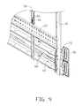
- FIG. 9 is an assembled, isometric view of FIG. 1 , but viewed from another aspect
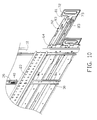
- FIG. 10 is similar to FIG. 9 , but shows a using state
- FIGS. 11 and 12 respectively show position relations of the rod and two interlocking members of FIG. 9 and FIG. 10 .
- an interlocking mechanism for sliding rails in accordance with an embodiment of the present invention is disposed in a cabinet.
- the interlocking mechanism includes a rod 30, a first elastic member 40, and a plurality of locking subassemblies 100.
- the locking subassembly 100 includes a retaining member 60, an interlocking member 70, a locking member 80, a second elastic member 42, and a blocking member 90.
- the first elastic member 40 and the second elastic member 42 are helical springs.
- Each locking subassembly 100 is attached to a sliding rail 50.
- the cabinet includes two columns 10, and a beam 20 perpendicularly attached to the columns 10.
- a receiving portion 22 is attached to the middle part of the beam 20.
- the cross section of the receiving portion 22 is C-shaped.
- the receiving portion 22 defines a hook hole 221 at the upside thereof.
- the cross section of the rod 30 is C-shaped.
- the rod 30 includes a plurality of protrusions 32 and resilient members 34.
- the resilient members 34 are arranged along the length of the rod 30.
- Each protrusion 32 extends from the rod 30 adjacent a free end of a corresponding resilient member 34.
- the resilient members 34 slantingly extend from the rod 30.
- Each resilient member 34 and the corresponding protrusion 32 can lock a locking subassembly 100 in position preventing a corresponding server mounted to a corresponding sliding rail 50 from being drawn out of the cabinet.
- a side opposite to the protrusions 32 of the rod 30 has a hook portion 36 defining a hole therein to receive one end of the first elastic member 40(see FIGS. 9 and 10 ).
- Each sliding rail 50 includes an outer rail 52 and an inner rail 54 slidably mounted to the outer rail 52.
- the outer rail 52 and the inner rail 54 respectively define a plurality of screw holes.
- the retaining member 60 includes a fixing portion 62 and a retaining portion 64 extending from the top of the fixing portion 62.
- the fixing portion 62 defines a plurality of fixing holes 622.
- the retaining portion 64 includes a bottom side 66 perpendicularly extending from the top of the fixing portion 62, a top side 65 parallel to the bottom side 66, and a vertical side 68 vertically connecting the corresponding edges of the top side 65 and the bottom side 66.
- a junction of the top side 66 and the vertical side 68 defines a first hole 652.
- a junction of the bottom side 66 and the fixing portion 62 defines a second hole 662.
- a blocking tab 682 extends inwards from an end of the vertical side 68, adjacent the top side 65.
- a supporting tab 684 extends inwards from the vertical side 68 adjacent the bottom side 66 and the first hole 652.
- the interlocking member 70 includes a body 71, a grip 72 extends from an end of the body 71, and an interlocking portion 73 extending from a top of the body 71.
- the interlocking portion 73 includes a top side 74 perpendicularly extending from the top of the body 71, a vertical side 75 perpendicularly extending down from a side of the top side 74, and a bottom side 76 perpendicularly extending inwards from the vertical side 75.
- the top side 74 defines a slanting slot 742.
- a junction of the top side 74 and the vertical side 75 defines a driving portion 752 in the middle part.
- the driving portion 752 includes a rectangle-shaped receiving part 753 defined in the top side 74, and a trapezoid-shaped guiding part 754 defined in the vertical side 75.
- the body 71 defines a rectangle-shaped receiving hole 712 adjacent the driving portion 752 in the middle part thereof, and a hook hole 714 adjacent a side of the receiving hole 712.
- the bottom side 76 defines a trumpet-shaped retaining opening 762 corresponding to the driving portion 752.
- the retaining opening 762 includes a trapezoid-shaped guiding part 764 in the distal edge of the bottom side 76, and a rectangle-shaped retaining part 763 adjacent the vertical side 75.
- the locking member 80 includes a body 82 and a grip 81 extends from an end of the body 82.
- the grip 81 defines a depressed portion in a side facing the interlocking member 70.
- An L-shaped locking portion 83 extends from an upper portion of the body 82.
- Two supporting portions 86 spaced from each other are attached to the body 82 below the locking portion 83.
- Each supporting portion 86 defines a plurality of fixing holes 862.
- Two retaining portions 87 spaced from each other extend up from the body 82.
- the body 82 defines a hook hole 822 between the retaining portions 87.
- the locking portion 83 includes a top side 84 perpendicularly extending from the body 82, and a vertical side 85 vertically extending down from an edge opposite to the body 82 of the top side 84.
- a protrusion 842 protrudes up from a junction of the body 82 and the top side 84, adjacent the grip 81.
- the top side 84 defines a peg hole 844 adjacent the protrusion 842, and a nearby arc-shaped slot 846 having a same center point as the peg hole 844.
- a junction of the top side 84 and the vertical side 85 defines a through hole 847.
- the retaining potions 87 respectively define a plurality of L-shaped fixing slots 872, configured for fixing a server to the locking member 80.
- the blocking member 90 includes a blocking part 92, a sliding post 95, and a peg 96.
- the blocking part 92 is polygon-shaped, and defines a pivot hole 922 and a fixing hole 924 therein.
- the blocking part 92 further defines a blocking surface 925 adjacent the fixing hole 924.
- a resilient portion 93 extends from a side surface of the blocking part 92.
- the interlocking member 70 is slidably engaged between the locking portion 83 and the body 82 of the locking member 80.
- the interlocking member grip 72 is received in the depressed portion of the locking member grip 81, and abuts against a first end adjacent the locking portion 83 of the locking member grip 81.
- the driving portion 752 and the slanting slot 742 of the interlocking member 70 respectively align with the through hole 847 and the arc-shaped slot 846 of the locking member 80.
- the second elastic member 42 is received in the receiving hole 712 of the interlocking member body 71.
- Two ends of the second elastic member 42 respectively hook the hook hole 714 of the interlocking member body 71 and the hook hole 822 of the interlocking member body 82.
- the blocking part 92 of the blocking member 90 is placed on the top side 84 of the locking member 80.
- the sliding post 95 is fixed in the fixing hole 924 of the blocking part 92.
- a lower end of the sliding post 95 is slidably received in the arc-shaped slot 846 of the locking portion 83 of the locking member 80 and the slanting slot 742 of the interlocking portion 73 of the interlocking member 70, and is located at first ends of the arc-shaped slot 846 and the slanting slot 742 that are adjacent the vertical side 85 of the locking portion 83 of the locking member 80.
- the peg 96 rotatably passes through the pivot hole 922 of the blocking part 92, and engages in the peg hole 844 of the locking portion 83 of the locking member 80.
- a free end of the resilient portion 93 of the blocking part 92 resists against the protrusion 842 of the locking portion 83 of the locking member 80 (see FIG. 10 ).
- a plurality of screws passes through the fixing holes 862 of the supporting portion 86 of the locking member 80 and screws into the screw holes of the inner rail 54 to secure the inner rail 50 to the locking subassembly 100.
- a plurality of screws passes through the fixing holes 622 of the fixing portion 62 of the retaining member 60 and screws into the screw holes of the outer rail 52 of the sliding rail 50 to secure the outer rail 52 to the locking subassembly 100.
- the retaining portion 64 covers the locking portion 83 of the locking member 80.
- the supporting tab 684 of the retaining portion 64 slidably abuts against the bottom side 76 of the interlocking portion 73 of the interlocking member 70.
- the blocking surface 925 of the blocking part 92 is blocked by an end of the blocking tab 682 of the retaining member 60, thus the locking member 80 cannot slide relative to the retaining member 60, and the inner rail 54 of the sliding rail 50 cannot slide relative to the outer rail 52; correspondingly, a server fixed to the retaining portion 87 of the locking member 80 cannot move.
- the first hole 652 of the retaining member 60, the driving portion 752 of the interlocking member 70, and the through hole 847 of the locking member 80 are in alignment.
- the second hole 662 of the retaining member 60 and the retaining opening 762 of the interlocking member 70 are in alignment as well.
- the rod 30 slidably passes through the receiving portion 22 of the beam 20.
- Two ends of the first elastic member 40 respectively hook the hook portion 36 of the rod 30 and the hook hole 221 of the receiving portion 22.
- a plurality of fixing means (such as screws fixes the retaining member 60 of each locking subassembly 100 to the columns 10 parallel to the beam 20.
- a corresponding protrusion 32 of the rod 30 extends through the first hole 652 of the retaining member 60, the through hole 847 of the locking member 80, and the receiving part 753 of the driving portion 752 of the interlocking member 70; and is blocked by the driving portion guiding part 754.
- a corresponding resilient member 34 of the rod 30 extends through the second hole 662 of the retaining member 60 and the retaining opening guiding part 764 of the interlocking member 70 (see FIG. 11 ).
- the action causes the corresponding interlocking member grip 72 to abut against a second end away from the locking portion 83 of the locking member grip 81.
- the second elastic member 42 is deformed.
- the interlocking member 70 slides relative to the locking member 80; an edge of the slanting slot 742 of the locking member 70 pushes the sliding post 95 of the blocking member 90 to move to second ends of the slanting slot 742 and the arc-shaped slot 846 of the locking member 80 that are opposite to their first ends; the blocking part 92 rotates around the peg 96, and the resilient portion 93 deforms.
- An edge of the driving portion guiding part 754 of the interlocking member 70 pushes the corresponding protrusion 32 of the rod 30 to slide out of the driving portion 752 and move onto the interlocking member top side 74.
- the corresponding resilient member 34 of the rod 30 moves upwards along the retaining opening guiding part 764, and is deformed by an edge of the retaining opening guiding part 764.
- the corresponding resilient member 34 slides along the edge of the retaining opening guiding part 764 to an edge of the interlocking member bottom side 76.
- the first elastic member 40 is deformed.
- the blocking surface 925 of the blocking part 92 moves away from the blocking tab 682 of the retaining member 60, such that the locking member 80, the server fixed at the locking member 80, the interlocking member 70, and the inner rail 54 can slide relative to the cabinet, the retaining member 60, and the outer rail 52.
- the resilient members 34 are angled away from the rod 30, the resilient members 34 corresponding to the other servers move to the retaining parts 763 of the retaining openings 762 of the interlocking members 70 of the corresponding locking subassemblies 100.
- the servers fixed at these locking subassemblies 100 cannot be pulled out of the cabinet.
- the interlocking member 70 slides to its original position via the restoration of the second elastic member 42.
- the sliding post 95 of the blocking member 90 is pushed by the edge of the slanting slot 742 of the interlocking member 70 to slide to the first ends of the slanting slot 742 and the arc-shaped slot 846 of the locking member 80.
- the resilient portion 93 restores to help the blocking part 92 of the blocking member 90 to rotate, and the blocking surface 925 of the blocking part 92 is blocked by the blocking tab 682 of the retaining member 60.
- the rod 30 slides to its original position via the restoration of the first elastic member 40. Then any one of the servers can be pulled out of the cabinet by operating the interlocking member 70 of the corresponding locking subassemblies 100.
- the locking members 80 and the blocking members 90 can be omitted, and the interlocking members 70 are directly fixed to the inner rails 54 of the corresponding sliding rails 50.
- the inner rails 54 define a plurality of fixing slots to fix servers. The present invention will achieve a similar effect.
Landscapes
- Drawers Of Furniture (AREA)
- Support Devices For Sliding Doors (AREA)
- Lock And Its Accessories (AREA)
- Casings For Electric Apparatus (AREA)
Abstract
Description
- The present invention relates to an interlocking mechanism for sliding rails, and more particularly to an interlocking mechanism disposed in a cabinet to interlock sliding rails.
- Generally, servers are movably disposed in a cabinet on sliding rails and arranged vertically. The servers can be pushed into or pulled out of the cabinet easily. However, if several servers in the cabinet are pulled out, the center of gravity of the cabinet might shift, which may result in the cabinet tipping over.
- What is needed, therefore, is an interlocking mechanism to prevent several servers of the cabinet from being pulled out.
-
FIG. 1 is an exploded, isometric view of an interlocking mechanism for sliding rails in accordance with an embodiment of the present invention together with a rack of a cabinet, the interlocking mechanism includes a rod, and a plurality of locking subassemblies; -
FIG. 2 is an exploded, isometric view of one of the locking subassemblies ofFIG. 1 together with a sliding rail, the locking subassembly includes an interlocking member; -
FIG. 3 is similar toFIG. 2 , but viewed from another aspect; -
FIG. 4 is an enlarged view of an encircled portion IV ofFIG. 3 ; -
FIG. 5 is a partial front elevational view of the interlocking member ofFIG. 3 ; -
FIG. 6 is a partial bottom plan view of the interlocking member ofFIG. 3 ; -
FIG. 7 is an assembled, isometric view ofFIG. 3 ; -
FIG. 8 is an enlarged view of an encircled portion VIII ofFIG. 7 ; -
FIG. 9 is an assembled, isometric view ofFIG. 1 , but viewed from another aspect; -
FIG. 10 is similar toFIG. 9 , but shows a using state; and -
FIGS. 11 and12 respectively show position relations of the rod and two interlocking members ofFIG. 9 andFIG. 10 . - Referring to
FIGS. 1 to 3 , an interlocking mechanism for sliding rails in accordance with an embodiment of the present invention is disposed in a cabinet. The interlocking mechanism includes arod 30, a firstelastic member 40, and a plurality oflocking subassemblies 100. Thelocking subassembly 100 includes aretaining member 60, an interlockingmember 70, alocking member 80, a secondelastic member 42, and a blockingmember 90. In this embodiment the firstelastic member 40 and the secondelastic member 42 are helical springs. Eachlocking subassembly 100 is attached to a slidingrail 50. - The cabinet includes two
columns 10, and abeam 20 perpendicularly attached to thecolumns 10. Areceiving portion 22 is attached to the middle part of thebeam 20. The cross section of thereceiving portion 22 is C-shaped. Thereceiving portion 22 defines ahook hole 221 at the upside thereof. - The cross section of the
rod 30 is C-shaped. Therod 30 includes a plurality ofprotrusions 32 andresilient members 34. Theresilient members 34 are arranged along the length of therod 30. Eachprotrusion 32 extends from therod 30 adjacent a free end of a correspondingresilient member 34. Theresilient members 34 slantingly extend from therod 30. Eachresilient member 34 and thecorresponding protrusion 32 can lock a locking subassembly 100 in position preventing a corresponding server mounted to a corresponding slidingrail 50 from being drawn out of the cabinet. A side opposite to theprotrusions 32 of therod 30 has ahook portion 36 defining a hole therein to receive one end of the first elastic member 40(seeFIGS. 9 and10 ). - Each sliding
rail 50 includes anouter rail 52 and aninner rail 54 slidably mounted to theouter rail 52. Theouter rail 52 and theinner rail 54 respectively define a plurality of screw holes. - The
retaining member 60 includes afixing portion 62 and aretaining portion 64 extending from the top of thefixing portion 62. Thefixing portion 62 defines a plurality offixing holes 622. Theretaining portion 64 includes abottom side 66 perpendicularly extending from the top of thefixing portion 62, atop side 65 parallel to thebottom side 66, and avertical side 68 vertically connecting the corresponding edges of thetop side 65 and thebottom side 66. A junction of thetop side 66 and thevertical side 68 defines afirst hole 652. A junction of thebottom side 66 and thefixing portion 62 defines asecond hole 662. Ablocking tab 682 extends inwards from an end of thevertical side 68, adjacent thetop side 65. A supportingtab 684 extends inwards from thevertical side 68 adjacent thebottom side 66 and thefirst hole 652. - Referring also to
FIGS. 5 and6 , the interlockingmember 70 includes abody 71, agrip 72 extends from an end of thebody 71, and an interlockingportion 73 extending from a top of thebody 71. The interlockingportion 73 includes atop side 74 perpendicularly extending from the top of thebody 71, avertical side 75 perpendicularly extending down from a side of thetop side 74, and abottom side 76 perpendicularly extending inwards from thevertical side 75. Thetop side 74 defines aslanting slot 742. A junction of thetop side 74 and thevertical side 75 defines adriving portion 752 in the middle part. Thedriving portion 752 includes a rectangle-shaped receivingpart 753 defined in thetop side 74, and a trapezoid-shaped guidingpart 754 defined in thevertical side 75. Thebody 71 defines a rectangle-shaped receiving hole 712 adjacent thedriving portion 752 in the middle part thereof, and ahook hole 714 adjacent a side of thereceiving hole 712. Thebottom side 76 defines a trumpet-shaped retaining opening 762 corresponding to thedriving portion 752. Theretaining opening 762 includes a trapezoid-shaped guidingpart 764 in the distal edge of thebottom side 76, and a rectangle-shaped retainingpart 763 adjacent thevertical side 75. - Referring also to
FIGS. 2 to 4 , thelocking member 80 includes abody 82 and agrip 81 extends from an end of thebody 82. Thegrip 81 defines a depressed portion in a side facing the interlockingmember 70. An L-shaped locking portion 83 extends from an upper portion of thebody 82. Two supportingportions 86 spaced from each other are attached to thebody 82 below thelocking portion 83. Each supportingportion 86 defines a plurality offixing holes 862. Two retainingportions 87 spaced from each other extend up from thebody 82. Thebody 82 defines ahook hole 822 between theretaining portions 87. Thelocking portion 83 includes atop side 84 perpendicularly extending from thebody 82, and avertical side 85 vertically extending down from an edge opposite to thebody 82 of thetop side 84. Aprotrusion 842 protrudes up from a junction of thebody 82 and thetop side 84, adjacent thegrip 81. Thetop side 84 defines apeg hole 844 adjacent theprotrusion 842, and a nearby arc-shaped slot 846 having a same center point as thepeg hole 844. A junction of thetop side 84 and thevertical side 85 defines a throughhole 847. Theretaining potions 87 respectively define a plurality of L-shaped fixing slots 872, configured for fixing a server to thelocking member 80. - The blocking
member 90 includes a blockingpart 92, asliding post 95, and apeg 96. The blockingpart 92 is polygon-shaped, and defines apivot hole 922 and afixing hole 924 therein. The blockingpart 92 further defines a blockingsurface 925 adjacent the fixinghole 924. Aresilient portion 93 extends from a side surface of the blockingpart 92. - Referring also to
FIGS. 2 ,3 ,7 and8 , to assemble the lockingsubassembly 100, the interlockingmember 70 is slidably engaged between the lockingportion 83 and thebody 82 of the lockingmember 80. The interlockingmember grip 72 is received in the depressed portion of the lockingmember grip 81, and abuts against a first end adjacent the lockingportion 83 of the lockingmember grip 81. The drivingportion 752 and theslanting slot 742 of the interlockingmember 70 respectively align with the throughhole 847 and the arc-shapedslot 846 of the lockingmember 80. The secondelastic member 42 is received in the receivinghole 712 of the interlockingmember body 71. Two ends of the secondelastic member 42 respectively hook thehook hole 714 of the interlockingmember body 71 and thehook hole 822 of the interlockingmember body 82. The blockingpart 92 of the blockingmember 90 is placed on thetop side 84 of the lockingmember 80. The slidingpost 95 is fixed in the fixinghole 924 of the blockingpart 92. A lower end of the slidingpost 95 is slidably received in the arc-shapedslot 846 of the lockingportion 83 of the lockingmember 80 and theslanting slot 742 of the interlockingportion 73 of the interlockingmember 70, and is located at first ends of the arc-shapedslot 846 and theslanting slot 742 that are adjacent thevertical side 85 of the lockingportion 83 of the lockingmember 80. Thepeg 96 rotatably passes through thepivot hole 922 of the blockingpart 92, and engages in thepeg hole 844 of the lockingportion 83 of the lockingmember 80. A free end of theresilient portion 93 of the blockingpart 92 resists against theprotrusion 842 of the lockingportion 83 of the locking member 80 (seeFIG. 10 ). - A plurality of screws passes through the fixing
holes 862 of the supportingportion 86 of the lockingmember 80 and screws into the screw holes of theinner rail 54 to secure theinner rail 50 to the lockingsubassembly 100. A plurality of screws passes through the fixingholes 622 of the fixingportion 62 of the retainingmember 60 and screws into the screw holes of theouter rail 52 of the slidingrail 50 to secure theouter rail 52 to the lockingsubassembly 100. The retainingportion 64 covers the lockingportion 83 of the lockingmember 80. The supportingtab 684 of the retainingportion 64 slidably abuts against thebottom side 76 of the interlockingportion 73 of the interlockingmember 70. The blockingsurface 925 of the blockingpart 92 is blocked by an end of theblocking tab 682 of the retainingmember 60, thus the lockingmember 80 cannot slide relative to the retainingmember 60, and theinner rail 54 of the slidingrail 50 cannot slide relative to theouter rail 52; correspondingly, a server fixed to the retainingportion 87 of the lockingmember 80 cannot move. Here, thefirst hole 652 of the retainingmember 60, the drivingportion 752 of the interlockingmember 70, and the throughhole 847 of the lockingmember 80 are in alignment. Thesecond hole 662 of the retainingmember 60 and the retainingopening 762 of the interlockingmember 70 are in alignment as well. - Referring also to
FIGS. 1 ,9 and11 , therod 30 slidably passes through the receivingportion 22 of thebeam 20. Two ends of the firstelastic member 40 respectively hook thehook portion 36 of therod 30 and thehook hole 221 of the receivingportion 22. A plurality of fixing means (such as screws fixes the retainingmember 60 of each lockingsubassembly 100 to thecolumns 10 parallel to thebeam 20. A correspondingprotrusion 32 of therod 30 extends through thefirst hole 652 of the retainingmember 60, the throughhole 847 of the lockingmember 80, and the receivingpart 753 of the drivingportion 752 of the interlockingmember 70; and is blocked by the drivingportion guiding part 754. A correspondingresilient member 34 of therod 30 extends through thesecond hole 662 of the retainingmember 60 and the retainingopening guiding part 764 of the interlocking member 70 (seeFIG. 11 ). - Referring also to
FIGS. 9 to 12 , when one of the servers is pulled out, the action causes the corresponding interlockingmember grip 72 to abut against a second end away from the lockingportion 83 of the lockingmember grip 81. The secondelastic member 42 is deformed. In this course, the interlockingmember 70 slides relative to the lockingmember 80; an edge of theslanting slot 742 of the lockingmember 70 pushes the slidingpost 95 of the blockingmember 90 to move to second ends of theslanting slot 742 and the arc-shapedslot 846 of the lockingmember 80 that are opposite to their first ends; the blockingpart 92 rotates around thepeg 96, and theresilient portion 93 deforms. An edge of the drivingportion guiding part 754 of the interlockingmember 70 pushes the correspondingprotrusion 32 of therod 30 to slide out of the drivingportion 752 and move onto the interlockingmember top side 74. The correspondingresilient member 34 of therod 30 moves upwards along the retainingopening guiding part 764, and is deformed by an edge of the retainingopening guiding part 764. The correspondingresilient member 34 slides along the edge of the retainingopening guiding part 764 to an edge of the interlockingmember bottom side 76. The firstelastic member 40 is deformed. The blockingsurface 925 of the blockingpart 92 moves away from theblocking tab 682 of the retainingmember 60, such that the lockingmember 80, the server fixed at the lockingmember 80, the interlockingmember 70, and theinner rail 54 can slide relative to the cabinet, the retainingmember 60, and theouter rail 52. - Because the
resilient members 34 are angled away from therod 30, theresilient members 34 corresponding to the other servers move to the retainingparts 763 of the retainingopenings 762 of the interlockingmembers 70 of thecorresponding locking subassemblies 100. The servers fixed at these lockingsubassemblies 100 cannot be pulled out of the cabinet. - When the server is pushed back into the cabinet, the interlocking
member 70 slides to its original position via the restoration of the secondelastic member 42. The slidingpost 95 of the blockingmember 90 is pushed by the edge of theslanting slot 742 of the interlockingmember 70 to slide to the first ends of theslanting slot 742 and the arc-shapedslot 846 of the lockingmember 80. Theresilient portion 93 restores to help the blockingpart 92 of the blockingmember 90 to rotate, and the blockingsurface 925 of the blockingpart 92 is blocked by theblocking tab 682 of the retainingmember 60. Therod 30 slides to its original position via the restoration of the firstelastic member 40. Then any one of the servers can be pulled out of the cabinet by operating the interlockingmember 70 of thecorresponding locking subassemblies 100. - In other embodiments, the locking
members 80 and the blockingmembers 90 can be omitted, and the interlockingmembers 70 are directly fixed to theinner rails 54 of the corresponding sliding rails 50. Theinner rails 54 define a plurality of fixing slots to fix servers. The present invention will achieve a similar effect. - It is to be understood, however, that even though numerous characteristics and advantages of the present invention have been set forth in the foregoing description, together with details of the structure and function of the invention, the disclosure is illustrative only, and changes may be made in detail, especially in matters of shape, size, and arrangement of parts within the principles of the invention to the full extent indicated by the broad general meaning of the terms in which the appended claims are expressed.
Claims (14)
- An interlocking mechanism, comprising:a plurality of sliding rails mounted to a cabinet, each sliding rail comprising an outer rail and an inner rail slidably attached to the outer rail;a plurality of interlocking members capable of moving from a first position to a second position, each interlocking member defining a driving portion and a retaining opening, wherein the retaining opening comprises a guiding part and a retaining part; the interlocking members are respectively attached to the sliding rails; anda rod resiliently and slidably attached to the cabinet, wherein the rod is capable of moving from a third position to a forth position; and the rod comprises a plurality of protrusions and a plurality of corresponding resilient members, each resilient member is angled away from the rod such that the angle is open toward the direction the rod slides and corresponding to each of the interlocking members;on the condition that one of the interlocking members moves from the first position to the second position, the driving portion is capable of pushing the corresponding protrusion to drive the rod to move to the forth position, the retaining opening guiding part of the interlocking member is capable of deforming the corresponding resilient member, the other resilient members are capable of moving to the retaining opening retaining parts to lock the other interlocking members to prevent the corresponding sliding rails from sliding.
- The interlocking mechanism as claimed in claim 1, wherein the driving portion of the interlocking member is a trapezoid-shaped opening.
- The interlocking mechanism as claimed in claim 1, wherein the retaining opening guiding part of the interlocking member is trapezoid-shaped, the retaining opening retaining part is rectangle-shaped.
- The interlocking mechanism as claimed in claim 1 further comprising a first elastic member, wherein two ends of the first elastic member hook the cabinet and the rod respectively to bias the rod moving from the forth position to the third position.
- The interlocking mechanism as claimed in claim 1, wherein the interlocking member is fixed to the inner rail of the sliding rail.
- The interlocking mechanism as claimed in claim 1, wherein each of the resilient members comprises a first end and a second end, the first end is fixed to the rod, and the second end is free end.
- The interlocking mechanism as claimed in claim 6, wherein each of the protrusions extends from the rod adjacent the free end of a corresponding resilient member.
- The interlocking mechanism as claimed in claim 7, wherein each of the plurality of interlocking members further comprises an interlocking portion; the interlocking portion comprises a top side, a bottom side, and a vertical side connecting the top side and the bottom side; the driving portion is defined in the vertical side; the retaining opening is defined at the bottom side.
- The interlocking mechanism as claimed in claim 8 further comprising a plurality of retaining members corresponding to the plurality of sliding rails, wherein the outer rail of each the sliding rail is fixed to the corresponding retaining member, each retaining member defines a blocking tab protruding therefrom.
- The interlocking mechanism as claimed in claim 9, wherein each of the plurality of retaining members comprises a supporting tab abutting against the bottom side of the corresponding interlocking member.
- The interlocking mechanism as claimed in claim 10 further comprising a plurality of locking members and corresponding blocking members, corresponding to the plurality of sliding rails, and a plurality of corresponding second elastic members, wherein each blocking member is attached to the corresponding locking member and capable of blocking the blocking tab the corresponding retaining member to prevent the corresponding sliding rail from sliding; the inner rail of the sliding rail is fixed at the locking member; the interlocking member is slidably engaged between the inner rail and the locking member, and capable of separating the blocking member from the blocking tab on the condition that the interlocking member moves to the second position ; two ends of the second elastic member hook the interlocking member and the locking member to bias the interlocking member moving from the second position to the first position.
- The interlocking mechanism as claimed in claim 11, wherein each of the plurality of blocking members comprises a blocking part capable of being blocked by the blocking tab, and a peg rotatably passing through a pivot hole defined in the blocking part to engage in a peg hole defined in the locking member.
- The interlocking mechanism as claimed in claim 12, wherein each of the plurality of blocking members further comprises a sliding post engaged in a fixing hole defined in the blocking part; each of the plurality of locking members defines an arc-shaped slot having a same center point as the peg hole thereof, and each of the plurality of interlocking member defines a slanting slot correspondingly; an end of the sliding post is slidably received in the corresponding interlocking member's slanting slot and the locking member's arc-shaped slot, and locates at first ends of the slanting slot and the arc-shaped slot; on the condition that the interlocking member slides, an edge of the slanting slot is capable of pushing the sliding post to move to second ends of the slanting slot and the arc-shaped slot to drive the blocking part to rotate, such that the blocking part is capable of being divorced from the retaining member blocking tab.
- An assembly, comprising:a cabinet comprising two parallel columns and a beam perpendicularly attached to the columns;at least two interlocking members capable of moving from a first position to a second position, each comprising a driving portion and a retaining opening;a rod resiliently and slidably attached to the beam, wherein the rod is capable of moving from a third position to a forth position; the rod comprises at least two protrusions and at least two resilient members slantingly attached adjacent the protrusions respectively and corresponding to the at least two interlocking members; andat least two sliding rails attached to the columns, each sliding rail comprising an outer rail and an inner rail slidably attached to the outer rail;wherein the interlocking members are respectively attached to the inner rails of the sliding rails; each retaining opening comprises a guiding part and a retaining part;
on the condition that one of the interlocking members moves from the first position to the second position, each driving portion is capable of pushing the corresponding protrusion to drive the rod to move to the forth position, each retaining opening guiding part of the interlocking member is capable of deforming the corresponding resilient member, the rest of the at least two resilient members are capable of moving to rest of the retaining opening retaining parts to lock the rest of the at leat two interlocking members to prevent the corresponding sliding rails from sliding.
Applications Claiming Priority (1)
| Application Number | Priority Date | Filing Date | Title |
|---|---|---|---|
| CN2008103017013A CN101588691B (en) | 2008-05-21 | 2008-05-21 | Slide rail interlocking device |
Publications (3)
| Publication Number | Publication Date |
|---|---|
| EP2123855A2 true EP2123855A2 (en) | 2009-11-25 |
| EP2123855A3 EP2123855A3 (en) | 2013-01-02 |
| EP2123855B1 EP2123855B1 (en) | 2014-06-18 |
Family
ID=41060052
Family Applications (1)
| Application Number | Title | Priority Date | Filing Date |
|---|---|---|---|
| EP09151394.5A Expired - Fee Related EP2123855B1 (en) | 2008-05-21 | 2009-01-27 | Interlocking mechanism for sliding rails |
Country Status (4)
| Country | Link |
|---|---|
| US (1) | US8052229B2 (en) |
| EP (1) | EP2123855B1 (en) |
| JP (1) | JP5307626B2 (en) |
| CN (1) | CN101588691B (en) |
Families Citing this family (14)
| Publication number | Priority date | Publication date | Assignee | Title |
|---|---|---|---|---|
| KR101136986B1 (en) | 2011-11-18 | 2012-07-12 | 주식회사 두손씨에스티 | Server system |
| CN103075058B (en) * | 2013-02-06 | 2014-11-05 | 常州兴盛天和电器有限公司 | Drawer interlocking and locking device |
| CN104979761B (en) * | 2014-04-14 | 2017-11-17 | 施耐德电器工业公司 | Adjustable armrest and the power distribution cabinet with the adjustable armrest |
| CN104470280B (en) * | 2014-12-31 | 2016-07-06 | 国家电网公司 | Cabinet installed by a kind of electronic installation installing upright guide rail |
| CN106559966B (en) * | 2015-09-25 | 2019-02-01 | 川湖科技股份有限公司 | Sliding rail assembly with interlink lock device |
| CN106793664B (en) * | 2016-12-13 | 2022-06-14 | 无锡海达尔精密滑轨股份有限公司 | Sequentially movable slide rail for server cabinet |
| CN108112204B (en) * | 2018-01-22 | 2024-05-24 | 李志强 | A new inspection device |
| TWI659712B (en) * | 2018-04-02 | 2019-05-21 | 川湖科技股份有限公司 | Slide rail assembly |
| CN109548333B (en) * | 2018-11-29 | 2020-12-29 | 英业达科技有限公司 | A resettable tenon device and a server using the resettable tenon device |
| CN114096106B (en) * | 2020-08-24 | 2024-08-06 | 川湖科技股份有限公司 | Slide rail assembly |
| CN112764482B (en) * | 2021-01-18 | 2023-03-14 | 英业达科技有限公司 | Server casing |
| CN113126707B (en) * | 2021-03-12 | 2023-02-28 | 山东英信计算机技术有限公司 | Node interlocking server |
| TWI817122B (en) * | 2021-05-14 | 2023-10-01 | 緯穎科技服務股份有限公司 | Handle module, server and server system |
| TWI842633B (en) * | 2023-09-23 | 2024-05-11 | 川湖科技股份有限公司 | Supporting assembly |
Citations (1)
| Publication number | Priority date | Publication date | Assignee | Title |
|---|---|---|---|---|
| GB2063355A (en) | 1979-11-15 | 1981-06-03 | Schaefer Gmbh Fritz | Interlocking drawers |
Family Cites Families (21)
| Publication number | Priority date | Publication date | Assignee | Title |
|---|---|---|---|---|
| US788966A (en) * | 1904-04-22 | 1905-05-02 | Henry Upton | Sectional filing-cabinet or the like. |
| US1613731A (en) * | 1925-04-04 | 1927-01-11 | Stockov Max | Wardrobe trunk |
| US1603483A (en) * | 1925-06-22 | 1926-10-19 | William S Masengale | Drawer-locking mechanism for trunks |
| DE1429493B1 (en) * | 1964-10-02 | 1970-12-03 | Breuninger & Groezinger Gmbh | Device for central locking of drawers arranged one above the other in drawer cabinets |
| US3259444A (en) * | 1965-01-21 | 1966-07-05 | Friend Irvin | Locking device for cabinet with two or more drawers |
| US3323849A (en) * | 1965-10-23 | 1967-06-06 | Art Metal Inc | Filing cabinet or the like |
| FR2158745A5 (en) * | 1971-10-25 | 1973-06-15 | Rhodaniens Atel | |
| US3874755A (en) * | 1973-10-29 | 1975-04-01 | Interstate Ind Inc | Anti-tilt lock mechanism |
| IT1014153B (en) * | 1974-05-09 | 1977-04-20 | Olivetti & Co Spa | CLOSING MECHANISM FOR A DRAWER FURNITURE |
| JPS5927824B2 (en) * | 1976-03-03 | 1984-07-09 | 村田機械株式会社 | drawer interlock device |
| JPS585010Y2 (en) * | 1979-09-20 | 1983-01-27 | 株式会社岡村製作所 | Anti-tipping locking device for goods storage |
| JP2588850Y2 (en) * | 1992-12-22 | 1999-01-20 | 株式会社イトーキクレビオ | Locking device for multi-stage drawer type cabinet |
| CN2381614Y (en) * | 1999-07-12 | 2000-06-07 | 谢玉英 | Sliding device for box movable door |
| JP2002306265A (en) * | 2001-04-19 | 2002-10-22 | Okamura Corp | Lock device for drawer in cabinet |
| US6749274B2 (en) * | 2001-10-03 | 2004-06-15 | Florian Westwinkel | Modular housing |
| US6722167B1 (en) * | 2003-05-28 | 2004-04-20 | Long-Jung Hsu | Cabinet lock |
| DE10329921B4 (en) * | 2003-07-02 | 2005-09-01 | Concord Gmbh | Child seat |
| US6896342B1 (en) * | 2004-07-08 | 2005-05-24 | E-Make Co., Ltd. | Cabinet anti-tilt safety apparatus |
| US7264319B2 (en) * | 2004-12-17 | 2007-09-04 | E-Make Co., Ltd. | Drawer locking apparatus of a cabinet |
| US7540573B2 (en) * | 2006-08-30 | 2009-06-02 | Ching-Hsiang Lin | Cabinet with a safety device |
| JP3140179U (en) * | 2007-12-27 | 2008-03-13 | 川湖科技股▲分▼有限公司 | Drawer interlock device |
-
2008
- 2008-05-21 CN CN2008103017013A patent/CN101588691B/en not_active Expired - Fee Related
- 2008-07-29 US US12/182,116 patent/US8052229B2/en not_active Expired - Fee Related
-
2009
- 2009-01-27 EP EP09151394.5A patent/EP2123855B1/en not_active Expired - Fee Related
- 2009-05-15 JP JP2009118784A patent/JP5307626B2/en not_active Expired - Fee Related
Patent Citations (1)
| Publication number | Priority date | Publication date | Assignee | Title |
|---|---|---|---|---|
| GB2063355A (en) | 1979-11-15 | 1981-06-03 | Schaefer Gmbh Fritz | Interlocking drawers |
Also Published As
| Publication number | Publication date |
|---|---|
| EP2123855B1 (en) | 2014-06-18 |
| US8052229B2 (en) | 2011-11-08 |
| JP2009283937A (en) | 2009-12-03 |
| EP2123855A3 (en) | 2013-01-02 |
| CN101588691A (en) | 2009-11-25 |
| US20090289533A1 (en) | 2009-11-26 |
| JP5307626B2 (en) | 2013-10-02 |
| CN101588691B (en) | 2013-04-24 |
Similar Documents
| Publication | Publication Date | Title |
|---|---|---|
| US8052229B2 (en) | Interlocking mechanism for sliding rails | |
| US7654624B2 (en) | Slide rail assembly | |
| US7580253B1 (en) | Retaining apparatus for disk drive | |
| US7744175B2 (en) | Slide rail assembly | |
| US7726755B2 (en) | Slide rail assembly | |
| US7708359B2 (en) | Latch mechanism for slide rail assembly | |
| US7744177B2 (en) | Mounting apparatus for slide rail | |
| US7345237B2 (en) | Mounting apparatus for data storage device | |
| US7355846B1 (en) | Mounting device for disk drive | |
| US20090315434A1 (en) | Mounting apparatus for slide rail | |
| US20090309471A1 (en) | Mounting apparatus for slide rail | |
| US20080159670A1 (en) | Ball bearing slide assembly | |
| KR101028010B1 (en) | Glass Door Frame Safety Guard | |
| US10714915B2 (en) | Vertical cable manager with slam-shut door | |
| US20080315741A1 (en) | Slide rail assembly | |
| US20090230277A1 (en) | Mounting apparatus for storage device | |
| US20060279925A1 (en) | Mounting apparatus for storage device | |
| US20080158845A1 (en) | Slide assembly with fixing device | |
| CN103513724B (en) | Chassis | |
| EP2128364A1 (en) | Locking system for furniture drawers | |
| US20070075200A1 (en) | Mounting apparatus for storage devices | |
| US20060279187A1 (en) | Detent pin bearing retainer lock for a drawer slide | |
| US6914778B2 (en) | Mounting peripheral devices using a mounting mechanism | |
| US7755886B2 (en) | Mounting apparatus for data storage devices | |
| JP4804945B2 (en) | Drawer guide rail assembly |
Legal Events
| Date | Code | Title | Description |
|---|---|---|---|
| PUAI | Public reference made under article 153(3) epc to a published international application that has entered the european phase |
Free format text: ORIGINAL CODE: 0009012 |
|
| AK | Designated contracting states |
Kind code of ref document: A2 Designated state(s): AT BE BG CH CY CZ DE DK EE ES FI FR GB GR HR HU IE IS IT LI LT LU LV MC MK MT NL NO PL PT RO SE SI SK TR |
|
| AX | Request for extension of the european patent |
Extension state: AL BA RS |
|
| PUAL | Search report despatched |
Free format text: ORIGINAL CODE: 0009013 |
|
| AK | Designated contracting states |
Kind code of ref document: A3 Designated state(s): AT BE BG CH CY CZ DE DK EE ES FI FR GB GR HR HU IE IS IT LI LT LU LV MC MK MT NL NO PL PT RO SE SI SK TR |
|
| AX | Request for extension of the european patent |
Extension state: AL BA RS |
|
| RIC1 | Information provided on ipc code assigned before grant |
Ipc: E05B 65/46 20060101AFI20121123BHEP |
|
| 17P | Request for examination filed |
Effective date: 20130624 |
|
| RBV | Designated contracting states (corrected) |
Designated state(s): AT BE BG CH CY CZ DE DK EE ES FI FR GB GR HR HU IE IS IT LI LT LU LV MC MK MT NL NO PL PT RO SE SI SK TR |
|
| AKX | Designation fees paid |
Designated state(s): DE FR GB |
|
| GRAP | Despatch of communication of intention to grant a patent |
Free format text: ORIGINAL CODE: EPIDOSNIGR1 |
|
| INTG | Intention to grant announced |
Effective date: 20140109 |
|
| GRAS | Grant fee paid |
Free format text: ORIGINAL CODE: EPIDOSNIGR3 |
|
| GRAA | (expected) grant |
Free format text: ORIGINAL CODE: 0009210 |
|
| AK | Designated contracting states |
Kind code of ref document: B1 Designated state(s): DE FR GB |
|
| REG | Reference to a national code |
Ref country code: GB Ref legal event code: FG4D |
|
| RIN1 | Information on inventor provided before grant (corrected) |
Inventor name: YU, MO-MING Inventor name: HE, XIANG-WEI |
|
| REG | Reference to a national code |
Ref country code: DE Ref legal event code: R096 Ref document number: 602009024704 Country of ref document: DE Effective date: 20140731 |
|
| REG | Reference to a national code |
Ref country code: DE Ref legal event code: R097 Ref document number: 602009024704 Country of ref document: DE |
|
| PLBE | No opposition filed within time limit |
Free format text: ORIGINAL CODE: 0009261 |
|
| STAA | Information on the status of an ep patent application or granted ep patent |
Free format text: STATUS: NO OPPOSITION FILED WITHIN TIME LIMIT |
|
| 26N | No opposition filed |
Effective date: 20150319 |
|
| REG | Reference to a national code |
Ref country code: DE Ref legal event code: R097 Ref document number: 602009024704 Country of ref document: DE Effective date: 20150319 |
|
| REG | Reference to a national code |
Ref country code: DE Ref legal event code: R119 Ref document number: 602009024704 Country of ref document: DE |
|
| GBPC | Gb: european patent ceased through non-payment of renewal fee |
Effective date: 20150127 |
|
| PG25 | Lapsed in a contracting state [announced via postgrant information from national office to epo] |
Ref country code: GB Free format text: LAPSE BECAUSE OF NON-PAYMENT OF DUE FEES Effective date: 20150127 Ref country code: DE Free format text: LAPSE BECAUSE OF NON-PAYMENT OF DUE FEES Effective date: 20150801 |
|
| REG | Reference to a national code |
Ref country code: FR Ref legal event code: ST Effective date: 20150930 |
|
| PG25 | Lapsed in a contracting state [announced via postgrant information from national office to epo] |
Ref country code: FR Free format text: LAPSE BECAUSE OF NON-PAYMENT OF DUE FEES Effective date: 20150202 |