EP2123555A2 - Directional control arrangement to provide stabilizing feedback to a structural bending mode - Google Patents
Directional control arrangement to provide stabilizing feedback to a structural bending mode Download PDFInfo
- Publication number
- EP2123555A2 EP2123555A2 EP09006243A EP09006243A EP2123555A2 EP 2123555 A2 EP2123555 A2 EP 2123555A2 EP 09006243 A EP09006243 A EP 09006243A EP 09006243 A EP09006243 A EP 09006243A EP 2123555 A2 EP2123555 A2 EP 2123555A2
- Authority
- EP
- European Patent Office
- Prior art keywords
- control
- link
- recited
- deflection
- tail
- Prior art date
- Legal status (The legal status is an assumption and is not a legal conclusion. Google has not performed a legal analysis and makes no representation as to the accuracy of the status listed.)
- Withdrawn
Links
- 230000000087 stabilizing effect Effects 0.000 title claims abstract description 10
- 238000005452 bending Methods 0.000 title description 6
- 230000004044 response Effects 0.000 claims abstract description 14
- 238000000034 method Methods 0.000 claims abstract description 7
- 230000033001 locomotion Effects 0.000 claims description 9
- 230000007935 neutral effect Effects 0.000 claims description 5
- RZVHIXYEVGDQDX-UHFFFAOYSA-N 9,10-anthraquinone Chemical compound C1=CC=C2C(=O)C3=CC=CC=C3C(=O)C2=C1 RZVHIXYEVGDQDX-UHFFFAOYSA-N 0.000 description 12
- 230000008901 benefit Effects 0.000 description 5
- 230000008859 change Effects 0.000 description 2
- 230000000368 destabilizing effect Effects 0.000 description 2
- 238000012986 modification Methods 0.000 description 2
- 230000004048 modification Effects 0.000 description 2
- 238000000926 separation method Methods 0.000 description 2
- 150000001875 compounds Chemical class 0.000 description 1
- 125000004122 cyclic group Chemical group 0.000 description 1
- 230000009977 dual effect Effects 0.000 description 1
- 230000000694 effects Effects 0.000 description 1
- 230000005284 excitation Effects 0.000 description 1
- 230000009467 reduction Effects 0.000 description 1
- 230000000153 supplemental effect Effects 0.000 description 1
- 239000013585 weight reducing agent Substances 0.000 description 1
Images




Classifications
-
- B—PERFORMING OPERATIONS; TRANSPORTING
- B64—AIRCRAFT; AVIATION; COSMONAUTICS
- B64C—AEROPLANES; HELICOPTERS
- B64C27/00—Rotorcraft; Rotors peculiar thereto
- B64C27/001—Vibration damping devices
-
- B—PERFORMING OPERATIONS; TRANSPORTING
- B64—AIRCRAFT; AVIATION; COSMONAUTICS
- B64C—AEROPLANES; HELICOPTERS
- B64C27/00—Rotorcraft; Rotors peculiar thereto
- B64C27/54—Mechanisms for controlling blade adjustment or movement relative to rotor head, e.g. lag-lead movement
- B64C27/56—Mechanisms for controlling blade adjustment or movement relative to rotor head, e.g. lag-lead movement characterised by the control initiating means, e.g. manually actuated
- B64C27/57—Mechanisms for controlling blade adjustment or movement relative to rotor head, e.g. lag-lead movement characterised by the control initiating means, e.g. manually actuated automatic or condition responsive, e.g. responsive to rotor speed, torque or thrust
-
- B—PERFORMING OPERATIONS; TRANSPORTING
- B64—AIRCRAFT; AVIATION; COSMONAUTICS
- B64C—AEROPLANES; HELICOPTERS
- B64C27/00—Rotorcraft; Rotors peculiar thereto
- B64C27/54—Mechanisms for controlling blade adjustment or movement relative to rotor head, e.g. lag-lead movement
- B64C27/58—Transmitting means, e.g. interrelated with initiating means or means acting on blades
- B64C27/59—Transmitting means, e.g. interrelated with initiating means or means acting on blades mechanical
-
- B—PERFORMING OPERATIONS; TRANSPORTING
- B64—AIRCRAFT; AVIATION; COSMONAUTICS
- B64C—AEROPLANES; HELICOPTERS
- B64C27/00—Rotorcraft; Rotors peculiar thereto
- B64C27/82—Rotorcraft; Rotors peculiar thereto characterised by the provision of an auxiliary rotor or fluid-jet device for counter-balancing lifting rotor torque or changing direction of rotorcraft
-
- B—PERFORMING OPERATIONS; TRANSPORTING
- B64—AIRCRAFT; AVIATION; COSMONAUTICS
- B64C—AEROPLANES; HELICOPTERS
- B64C27/00—Rotorcraft; Rotors peculiar thereto
- B64C27/04—Helicopters
-
- Y—GENERAL TAGGING OF NEW TECHNOLOGICAL DEVELOPMENTS; GENERAL TAGGING OF CROSS-SECTIONAL TECHNOLOGIES SPANNING OVER SEVERAL SECTIONS OF THE IPC; TECHNICAL SUBJECTS COVERED BY FORMER USPC CROSS-REFERENCE ART COLLECTIONS [XRACs] AND DIGESTS
- Y02—TECHNOLOGIES OR APPLICATIONS FOR MITIGATION OR ADAPTATION AGAINST CLIMATE CHANGE
- Y02T—CLIMATE CHANGE MITIGATION TECHNOLOGIES RELATED TO TRANSPORTATION
- Y02T50/00—Aeronautics or air transport
- Y02T50/40—Weight reduction
-
- Y—GENERAL TAGGING OF NEW TECHNOLOGICAL DEVELOPMENTS; GENERAL TAGGING OF CROSS-SECTIONAL TECHNOLOGIES SPANNING OVER SEVERAL SECTIONS OF THE IPC; TECHNICAL SUBJECTS COVERED BY FORMER USPC CROSS-REFERENCE ART COLLECTIONS [XRACs] AND DIGESTS
- Y10—TECHNICAL SUBJECTS COVERED BY FORMER USPC
- Y10T—TECHNICAL SUBJECTS COVERED BY FORMER US CLASSIFICATION
- Y10T74/00—Machine element or mechanism
- Y10T74/20—Control lever and linkage systems
- Y10T74/20396—Hand operated
- Y10T74/20402—Flexible transmitter [e.g., Bowden cable]
Definitions
- the present invention relates to a control system, and more particularly to a control system for a rotary-wing aircraft which reduces vibration.
- Tail rotor assembly provides yaw thrust to counteract induced torque generated by the main rotor assembly and provide yaw directional control.
- Aircraft structures typically have several bending modes with frequencies which may be within the bandwidth of the control system. If an excitation such as turbulence excites the bending mode, airframe vibration and deflection results. In some instances, airframe deflections induce control system inputs that affect this mode and cause destabilizing feedback which may increase the magnitude of the vibration.
- a control system includes: a control; and a link connected to the control, the link oriented to generate a control output in the control in response to a deflection, the control output operable to at least partially resist the deflection.
- a rotary wing aircraft includes: an airframe comprising an extending tail; a tail rotor system mounted to the extending tail; an input; and a link which connects the input to the tail rotor system, the link oriented to generate a pitch output in the tail rotor system in response to a deflection of the extending tail, the pitch output operable to at least partially resist the deflection.
- a method of producing a stabilizing feedback includes: orienting a link within a structure; and generating a control output with the link in response to a deflection of the structure, the control output operable to at least partially resist the deflection.
- FIG. 1 schematically illustrates a rotary-wing aircraft 10 having a main rotor system 12.
- the aircraft 10 includes an airframe 14 having an extending tail 16 which mounts a tail rotor system 18.
- the main rotor system 12 is driven about an axis of rotation R through a main rotor gearbox (MGB) 20 by a multi-engine powerplant system 22.
- the multi-engine powerplant system 22 is integrated with the MGB 20 to drive the main rotor system 12 and the tail rotor system 18.
- the multi-engine powerplant system 22 generates the power available for flight operations and couples such power to the main rotor system 12 through the MGB.
- the main rotor system 12 includes a multiple of rotor blades 24 mounted to a rotor hub 26.
- helicopter configuration is illustrated and described in the disclosed embodiment, other configurations and/or machines, such as high speed compound rotary-wing aircraft with supplemental translational thrust systems, dual contrarotating, coaxial rotor system aircraft, turbo-props, tilt-rotors and tilt-wing aircraft, will also benefit from the present invention.
- the tail rotor system 18 is controlled by a flight control system 30.
- the flight control system 30 ( Figure 2B ) disclosed herein operates a control such as the tail rotor system 18 to provide a control output such as a pitch control output. It should be understood that the flight control system 30 could be utilized to selectively generate a control output for any aircraft systems or control surfaces. Furthermore, other controls which are used on fixed wing aircraft, vehicles, ships and elsewhere outside the aircraft field may also benefit herefrom.
- the flight control system 30 includes an input such as a pilot actuated pedal system 32 which imparts pilot control motion to a mixing unit 34.
- the mixing unit 34 typically includes a system of rods and bell cranks which coordinate or "mix” the pedal, cyclic and collective control inputs then communicates the "mixed” input to other controls and servos.
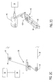
- the pedal system 32 positions a forward control quadrant 36 ( Figure 2C ) either directly or through the mixing unit 34.
- the forward control quadrant 36 is mounted for rotational motion about an axis of rotation 36A ( Figure 2C ).
- a set of links such as a set of flexible cables 38, 40 are connected to the forward control quadrant 36 at one end and connected at opposite ends to an aft control quadrant 42 ( Figure 2D ).
- "flexible” cables are cables which are capable of flexing but not stretching. It should be understood that although flexible cables are illustrated in the disclosed embodiment, other links such as rods may alternatively or additionally be provided.
- the aft control quadrant 42 is mounted for rotational motion about axis of rotation 42A ( Figure 2D ).
- the aft control quadrant 42 follows the pilot imparted motions of the forward control quadrant 36 due to the selective tension loading of flexible cables 38, 40 affected by the pilot in operation of the pedal system 32.
- the aft control quadrant 42 drives a tail rotor servo 46 which controls the pitch output of the tail rotor system 18.
- the path of the flexible cables 38, 40 is established by a multiple of roller systems 44 through which the cables 38, 40 are received so that the aft control quadrant 42 follows the pilot imparted motions of the forward control quadrant 36.
- the flexible cables 38, 40 are guided in their path between control quadrants 36, 42 so as to be free of obstructions and to proceed in a generally parallel relationship through the extended tail 16.
- the flexible cables 38, 40 are arranged in a separated relationship through the extended tail 16 to provide ballistic tolerance through separation. The separation locates the flexible cables 38, 40 off of a neutral axis N of the extended tail 16.
- a neutral axis is an axis upon which a structure such as the aircraft tail 16 ( Figure 2A ) may deflect such that links such as the flexible cables 38, 40 located along the neutral axis would essentially not be affected by the deflection of the structure. Since the flexible cables 38, 40 are located off the neutral axis N, the flexible cables 38, 40 receive an input when the extended tail 16 deflects.
- the flight control system 30 is schematically illustrated.
- the pedal system 32 imparts pilot control motion through the mixing unit 34 then to the forward control quadrant 36 from the forward control quadrant 36 the pilot control motion is transferred to the aft control quadrant 42 though the flexible cables 38, 40.
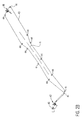
- the flexible cables 38, 40 are oriented to generate a pitch output and resulting thrust T in the tail rotor system 18 in response to a deflection of the extended tail 16 ( Figure 3B ) that at least partially resists the deflection of the extended tail 16. That is, the deflection of the extended tail 16 results in a deflection ( ⁇ ) which results in a relative change in length (L ⁇ ) of the flexible cables 38, 40.
- the relative change in length produces an input to the tail rotor system 18 in opposition to the deflection to thereby produce a stabilizing feedback.
- reversing systems 48 may be required to assure proper control output operation relative to control input. That is, reversing systems 48 may be required to assure that, for example, pilot port pedal (L) into the pedal system 32 resorts in a port output from the tail rotor system 18 and deflection of the extended tail 16 to the starboard results in a port output from the tail rotor system 18 to counter the deflection.
- L pilot port pedal
- reversing systems 48 may be separate systems or alternatively incorporated into the pedal system 32, mixing unit 34, forward control quadrant 36, aft control quadrant 42, tail rotor servo 46 combinations thereof or other components of the flight control system 30 to achieve both stabilizing feedback and proper control response.
- the stabilizing feedback is in contrast to a destabilizing feedback in which the linkages may be oriented in a manner which generates an output that magnifies the deflection of the extending tail. That is, airframe deflections caused by vibration may result in inputs to the tail rotor control cables which magnify tail shake response when the first lateral bending mode is excited.
- the stabilizing feedback operates to reduce aircraft vibration from even a no feedback condition in which airframe deflections provide no inputs to the tail rotor control cables. Stabilizing feedback thereby improves aircrew and passenger ride quality from a no feedback condition in combination with weight reduction through removal or reduction of aerodynamic fairings, beanies, extended decks and strakes.
Landscapes
- Engineering & Computer Science (AREA)
- Mechanical Engineering (AREA)
- Aviation & Aerospace Engineering (AREA)
- Mechanical Control Devices (AREA)
- Piezo-Electric Or Mechanical Vibrators, Or Delay Or Filter Circuits (AREA)
- Optical Communication System (AREA)
- Surface Acoustic Wave Elements And Circuit Networks Thereof (AREA)
Abstract
Description
- The present invention relates to a control system, and more particularly to a control system for a rotary-wing aircraft which reduces vibration.
- Many rotary-wing aircraft utilize a single main rotor assembly and a tail rotor assembly. The tail rotor assembly provides yaw thrust to counteract induced torque generated by the main rotor assembly and provide yaw directional control.
- Aircraft structures typically have several bending modes with frequencies which may be within the bandwidth of the control system. If an excitation such as turbulence excites the bending mode, airframe vibration and deflection results. In some instances, airframe deflections induce control system inputs that affect this mode and cause destabilizing feedback which may increase the magnitude of the vibration.
- In a rotary-wing aircraft, development effort has been expended to reduce vibration that may excite bending mode response within the extending tail. Although effective, systems such as aerodynamic fairings, beanies, extended decks and strakes may increase aircraft weight.
- A control system according to an exemplary aspect of the present invention includes: a control; and a link connected to the control, the link oriented to generate a control output in the control in response to a deflection, the control output operable to at least partially resist the deflection.
- A rotary wing aircraft according to an exemplary aspect of the present invention includes: an airframe comprising an extending tail; a tail rotor system mounted to the extending tail; an input; and a link which connects the input to the tail rotor system, the link oriented to generate a pitch output in the tail rotor system in response to a deflection of the extending tail, the pitch output operable to at least partially resist the deflection.
- A method of producing a stabilizing feedback according to an exemplary aspect of the present invention includes: orienting a link within a structure; and generating a control output with the link in response to a deflection of the structure, the control output operable to at least partially resist the deflection.
- The various features and advantages of this invention will become apparent to those skilled in the art from the following detailed description of the disclosed non-limiting embodiment. The drawings that accompany the detailed description can be briefly described as follows:
-
Figure 1 is a general perspective view of an exemplary rotary wing aircraft embodiment for use with the present invention; -
Figure 2A is a general partial phantom view of a flight control system in an exemplary rotary wing aircraft embodiment; -
Figure 2B is a general perspective view of a tail-rotor flight control system; -
Figure 2C is a pedal system input of the tail-rotor flight control system; -
Figure 2D is a tail rotor system output of the tail-rotor flight control system; -
Figure 3A is a schematic view of a tail-rotor flight control system; -
Figure 3B is a schematic view of the flexible cables in the tail-rotor flight control system ofFigure 3A oriented to generate a pitch output in a tail rotor system in response to a deflection of an extended tail of an aircraft fuselage; and -
Figure 4 is a vibratory response plot of a fuselage bending mode to wake turbulence effect of structural feedback into a tail rotor system. -
Figure 1 schematically illustrates a rotary-wing aircraft 10 having amain rotor system 12. Theaircraft 10 includes anairframe 14 having an extendingtail 16 which mounts atail rotor system 18. Themain rotor system 12 is driven about an axis of rotation R through a main rotor gearbox (MGB) 20 by amulti-engine powerplant system 22. Themulti-engine powerplant system 22 is integrated with the MGB 20 to drive themain rotor system 12 and thetail rotor system 18. Themulti-engine powerplant system 22 generates the power available for flight operations and couples such power to themain rotor system 12 through the MGB. Themain rotor system 12 includes a multiple ofrotor blades 24 mounted to arotor hub 26. Although a particular helicopter configuration is illustrated and described in the disclosed embodiment, other configurations and/or machines, such as high speed compound rotary-wing aircraft with supplemental translational thrust systems, dual contrarotating, coaxial rotor system aircraft, turbo-props, tilt-rotors and tilt-wing aircraft, will also benefit from the present invention. - Referring to
Figure 2A , thetail rotor system 18 is controlled by aflight control system 30. The flight control system 30 (Figure 2B ) disclosed herein operates a control such as thetail rotor system 18 to provide a control output such as a pitch control output. It should be understood that theflight control system 30 could be utilized to selectively generate a control output for any aircraft systems or control surfaces. Furthermore, other controls which are used on fixed wing aircraft, vehicles, ships and elsewhere outside the aircraft field may also benefit herefrom. - Referring to
Figure 2B , theflight control system 30 includes an input such as a pilot actuatedpedal system 32 which imparts pilot control motion to amixing unit 34. It should be understood that although thepedal system 32 is illustrated in the disclosed embodiment, other inputs such as flight or drive controls may alternatively or additionally be provided. Themixing unit 34 typically includes a system of rods and bell cranks which coordinate or "mix" the pedal, cyclic and collective control inputs then communicates the "mixed" input to other controls and servos. Thepedal system 32 positions a forward control quadrant 36 (Figure 2C ) either directly or through themixing unit 34. Theforward control quadrant 36 is mounted for rotational motion about an axis of rotation 36A (Figure 2C ). - A set of links such as a set of
flexible cables forward control quadrant 36 at one end and connected at opposite ends to an aft control quadrant 42 (Figure 2D ). As utilized herein, "flexible" cables are cables which are capable of flexing but not stretching. It should be understood that although flexible cables are illustrated in the disclosed embodiment, other links such as rods may alternatively or additionally be provided. Theaft control quadrant 42 is mounted for rotational motion about axis ofrotation 42A (Figure 2D ). - The
aft control quadrant 42 follows the pilot imparted motions of theforward control quadrant 36 due to the selective tension loading offlexible cables pedal system 32. Theaft control quadrant 42 drives atail rotor servo 46 which controls the pitch output of thetail rotor system 18. - The path of the
flexible cables roller systems 44 through which thecables aft control quadrant 42 follows the pilot imparted motions of theforward control quadrant 36. Theflexible cables control quadrants tail 16. Theflexible cables tail 16 to provide ballistic tolerance through separation. The separation locates theflexible cables extended tail 16. A neutral axis is an axis upon which a structure such as the aircraft tail 16 (Figure 2A ) may deflect such that links such as theflexible cables flexible cables flexible cables tail 16 deflects. - Referring to
Figure 3A , theflight control system 30 is schematically illustrated. Thepedal system 32 imparts pilot control motion through themixing unit 34 then to theforward control quadrant 36 from theforward control quadrant 36 the pilot control motion is transferred to theaft control quadrant 42 though theflexible cables flexible cables tail rotor system 18 in response to a deflection of the extended tail 16 (Figure 3B ) that at least partially resists the deflection of theextended tail 16. That is, the deflection of the extendedtail 16 results in a deflection (Δ) which results in a relative change in length (L±Δ) of theflexible cables tail rotor system 18 in opposition to the deflection to thereby produce a stabilizing feedback. - Numerous orientations of the
flexible cables reversing systems 48 may be required to assure proper control output operation relative to control input. That is,reversing systems 48 may be required to assure that, for example, pilot port pedal (L) into thepedal system 32 resorts in a port output from thetail rotor system 18 and deflection of theextended tail 16 to the starboard results in a port output from thetail rotor system 18 to counter the deflection. It should be understood that thereversing systems 48 may be separate systems or alternatively incorporated into thepedal system 32, mixingunit 34,forward control quadrant 36,aft control quadrant 42,tail rotor servo 46 combinations thereof or other components of theflight control system 30 to achieve both stabilizing feedback and proper control response. - Referring to
Figure 4 , the stabilizing feedback is in contrast to a destabilizing feedback in which the linkages may be oriented in a manner which generates an output that magnifies the deflection of the extending tail. That is, airframe deflections caused by vibration may result in inputs to the tail rotor control cables which magnify tail shake response when the first lateral bending mode is excited. - The stabilizing feedback operates to reduce aircraft vibration from even a no feedback condition in which airframe deflections provide no inputs to the tail rotor control cables. Stabilizing feedback thereby improves aircrew and passenger ride quality from a no feedback condition in combination with weight reduction through removal or reduction of aerodynamic fairings, beanies, extended decks and strakes.
- It should be understood that relative positional terms such as "forward," "aft," "upper," "lower," "above," "below," and the like are with reference to the normal operational attitude of the vehicle and should not be considered otherwise limiting.
- It should be understood that although a particular component arrangement is disclosed in the illustrated embodiment, other arrangements will benefit from the instant invention.
- Although particular step sequences are shown, described, and claimed, it should be understood that steps may be performed in any order, separated or combined unless otherwise indicated and will still benefit from the present invention.
- The foregoing description is exemplary rather than defined by the limitations within. Many modifications and variations are possible in light of the above teachings. Non-limiting embodiments are disclosed herein, however, one of ordinary skill in the art would recognize that certain modifications would come within the scope of this invention. It is, therefore, to be understood that within the scope of the appended claims, the invention may be practiced otherwise than as specifically described. For that reason the following claims should be studied to determine the true scope and content of this invention.
Claims (15)
- A control system comprising:a control; anda link connected to said control, said link oriented to generate a control output in said control in response to a deflection, said control output operable to at least partially resist said deflection.
- The system as recited in claim 1, wherein said control is a tail rotor.
- The system as recited in claim 2, wherein said link comprises a flexible cable.
- A rotary wing aircraft comprising:an airframe comprising an extended tail;an tail rotor system mounted to said extended tail;an input; anda link which connects said input to said tail rotor system, said link oriented to generate a pitch output in said tail rotor system in response to a deflection of said extended tail, said pitch output operable to at least partially resist said deflection.
- The aircraft as recited in claim 4, wherein said link comprises a flexible cable.
- The aircraft as recited in claim 4 or 5, wherein said input comprises a pedal system
- The aircraft as recited in claim 6, wherein said link is connected to said pedal system through a mixing unit.
- The aircraft as recited in any of claims 4 to 7, wherein said mixing unit positions a forward control quadrant connected to a first end section of said flexible cable, said forward control quadrant being mounted for rotational motion about an axis of rotation.
- The aircraft as recited in claim 8, further comprising an aft control quadrant connected to a second end section of said flexible cable, said aft control quadrant being mounted for rotational motion about an axis of rotation, said aft control quadrant rotating in response to said forward control quadrant.
- The aircraft as recited in claim 9, further comprising a servo which operates said tail rotor system, said aft control quadrant being operable to command said servo.
- A method of producing a stabilizing feedback comprising:orienting a link within a structure; andgenerating a control output with the link in response to a deflection of the structure, the control output being operable to at least partially resist the deflection.
- A method as recited in claim 11, wherein orienting the link comprises: orienting the link off of a neutral axis of the structure.
- A method as recited in claim 11 or 12, wherein orienting the link comprises: orienting a flexible cable within an extended tail of a rotary wing aircraft.
- A method as recited in any of claims 11 to 13, wherein generating the control output comprises:generating a yaw force opposite the deflection of the structure.
- A method as recited in any of claims 11 to 14, wherein generating the control output comprises:transmitting a pitch command to a tail rotor through the link.
Applications Claiming Priority (1)
| Application Number | Priority Date | Filing Date | Title |
|---|---|---|---|
| US12/123,420 US20090283628A1 (en) | 2008-05-19 | 2008-05-19 | Directional control arrangement to provide stabilizing feedback to a structural bending mode |
Publications (2)
| Publication Number | Publication Date |
|---|---|
| EP2123555A2 true EP2123555A2 (en) | 2009-11-25 |
| EP2123555A3 EP2123555A3 (en) | 2012-08-08 |
Family
ID=40902664
Family Applications (1)
| Application Number | Title | Priority Date | Filing Date |
|---|---|---|---|
| EP09006243A Withdrawn EP2123555A3 (en) | 2008-05-19 | 2009-05-07 | Directional control arrangement to provide stabilizing feedback to a structural bending mode |
Country Status (2)
| Country | Link |
|---|---|
| US (1) | US20090283628A1 (en) |
| EP (1) | EP2123555A3 (en) |
Families Citing this family (2)
| Publication number | Priority date | Publication date | Assignee | Title |
|---|---|---|---|---|
| KR101181425B1 (en) | 2010-04-30 | 2012-09-19 | 경북대학교 산학협력단 | An unmanned helicopter for spraying chemical |
| CN107364567B (en) * | 2017-07-26 | 2019-05-03 | 重庆通用航空产业集团有限公司 | A small helicopter tail rotor control system |
Family Cites Families (51)
| Publication number | Priority date | Publication date | Assignee | Title |
|---|---|---|---|---|
| US2843211A (en) * | 1954-12-28 | 1958-07-15 | United Aircraft Corp | Automatic tail rotor control |
| US3733039A (en) * | 1971-05-20 | 1973-05-15 | United Aircraft Corp | Feel augmentation control system for helicopters |
| US3747876A (en) * | 1971-06-01 | 1973-07-24 | Mc Donnell Douglas Corp | Variable load feel |
| US4170147A (en) * | 1977-10-27 | 1979-10-09 | United Technologies Corporation | Redundant flight control system |
| US4186622A (en) * | 1977-10-27 | 1980-02-05 | United Technologies Corporation | Redundant flight control system |
| US4198877A (en) * | 1978-07-07 | 1980-04-22 | The United States Of America As Represented By The Secretary Of The Air Force | Control cable fail safe device |
| US4206891A (en) * | 1978-10-26 | 1980-06-10 | United Technologies Corporation | Helicopter pedal feel force proportional to side slip |
| FR2444295A1 (en) * | 1978-12-13 | 1980-07-11 | Rech Mecanique Appliquee | CABLE VOLTAGE REGULATOR |
| US4245801A (en) * | 1979-02-15 | 1981-01-20 | United Technologies Corporation | Tail rotor control cable-pylon fold accommodation |
| US4345195A (en) * | 1979-12-13 | 1982-08-17 | Sperry Corporation | Strapdown multifunction servoactuator apparatus for aircraft |
| US4340335A (en) * | 1979-12-17 | 1982-07-20 | United Technologies Corporation | Helicopter tail rotor with pitch control mechanism |
| ES490715A0 (en) * | 1980-04-18 | 1981-02-16 | Campos Herruzo Juan | COAXIAL HELICOPTER DIRECTION CONTROL SYSTEM, COLLECTIVE PASS AT THE SAME TIME THAT ALSO VARIABLE SIMULTANEOUSLY WITH OPPOSITE SIGN |
| US4484486A (en) * | 1981-12-03 | 1984-11-27 | Westinghouse Electric Corp. | Concentric pulley drive assembly |
| US4531692A (en) * | 1982-03-15 | 1985-07-30 | Ernesto Mateus | Helicopter flight control and transmission system |
| US4540141A (en) * | 1983-09-22 | 1985-09-10 | United Technologies Corporation | Fail-safe tail rotor control system |
| US4529155A (en) * | 1983-12-09 | 1985-07-16 | United Technologies Corporation | Redundant tail rotor control system |
| US4648568A (en) * | 1985-05-28 | 1987-03-10 | Phillips Richard G | Emergency anti-torque control system and method for helicopters |
| GB8525631D0 (en) * | 1985-10-17 | 1985-11-20 | British Aerospace | Aircraft flying control systems |
| GB8629896D0 (en) * | 1986-12-15 | 1987-01-28 | Westland Plc | Helicopter flight control system |
| US4881874A (en) * | 1988-03-31 | 1989-11-21 | Bell Helicopter Textron Inc. | Tail rotor |
| US5232183A (en) * | 1991-03-06 | 1993-08-03 | The Boeing Company | Helicopter anti-torque control system utilizing exhaust gas |
| US5131604A (en) * | 1991-04-11 | 1992-07-21 | United Technologies Corporation | Helicopter antitorque device |
| US5149023A (en) * | 1991-07-12 | 1992-09-22 | The Boeing Company | Mechanically-linked side stick controllers with isolated pitch and roll control movement |
| FR2679199B1 (en) * | 1991-07-16 | 1997-01-31 | Aerospatiale | ANTICOUPLE SYSTEM FOR HELICOPTER. |
| US5188511A (en) * | 1991-08-27 | 1993-02-23 | United Technologies Corporation | Helicopter anti-torque device direct pitch control |
| US5597138A (en) * | 1991-09-30 | 1997-01-28 | Arlton; Paul E. | Yaw control and stabilization system for helicopters |
| US5209430A (en) * | 1991-11-07 | 1993-05-11 | The United States Of America As Represented By The Administrator Of The National Aeronautics And Space Administration | Helicopter low-speed yaw control |
| US5527004A (en) * | 1993-02-24 | 1996-06-18 | Helix Air, Inc. | Control system for aircraft |
| US5551652A (en) * | 1994-03-28 | 1996-09-03 | Mcdonnell Douglas Corporation | Standby control system |
| US5601257A (en) * | 1994-08-11 | 1997-02-11 | Benchmark Corporation | Air vehicle yaw control system |
| FR2728537A1 (en) * | 1994-12-21 | 1996-06-28 | Eurocopter France | DEVICE FOR ACTUATING A CONTROL MEMBER FOR AN AIRCRAFT, IN PARTICULAR A HELICOPTER, WITH ELECTRIC FLIGHT CONTROLS |
| FR2728541A1 (en) * | 1994-12-22 | 1996-06-28 | Eurocopter France | CYCLIC SLEEVE SYSTEM WITH GRADIENT FOR HELICOPTER |
| US5607122A (en) * | 1994-12-22 | 1997-03-04 | Bell Helicopter Textron Inc. | Tail rotor authority control for a helicopter |
| FR2728536A1 (en) * | 1994-12-22 | 1996-06-28 | Eurocopter France | PALIERIER SYSTEM WITH GRADIENT OF EFFORT FOR HELICOPTER |
| US5797564A (en) * | 1995-05-15 | 1998-08-25 | The Boeing Company | System for backdrive of flight deck controls during autopilot operation |
| US5806806A (en) * | 1996-03-04 | 1998-09-15 | Mcdonnell Douglas Corporation | Flight control mechanical backup system |
| US5749540A (en) * | 1996-07-26 | 1998-05-12 | Arlton; Paul E. | System for controlling and automatically stabilizing the rotational motion of a rotary wing aircraft |
| JP3051357B2 (en) * | 1997-03-26 | 2000-06-12 | 株式会社コミュータヘリコプタ先進技術研究所 | Main rotor torque correction device |
| US5924331A (en) * | 1997-07-08 | 1999-07-20 | Mcdonnell Douglas Corporation | Cable control system having stored energy fail-safe mechanism |
| FR2769284B1 (en) * | 1997-10-07 | 1999-12-03 | Eurocopter France | DEVICE FOR CONTROLLING AN AERODYNAMIC SURFACE FOR STEERING A HELICOPTER |
| FR2793765B1 (en) * | 1999-05-18 | 2001-07-13 | Eurocopter France | FLIGHT CONTROL DEVICE OF AN AIRCRAFT |
| US6405980B1 (en) * | 1999-07-26 | 2002-06-18 | Cartercopters, L.L.C. | Control system for rotor aircraft |
| US6254037B1 (en) * | 1999-08-06 | 2001-07-03 | Bell Helicopter Textron Inc. | Variable gradient control stick force feel adjustment system |
| FR2809373B1 (en) * | 2000-05-29 | 2002-08-09 | Aerospatiale Matra Airbus | ELECTRICAL CONTROL SYSTEM FOR AN AIRCRAFT STEERING GOVERNOR |
| US6416015B1 (en) * | 2001-05-01 | 2002-07-09 | Franklin D. Carson | Anti-torque and yaw-control system for a rotary-wing aircraft |
| US6644600B1 (en) * | 2002-04-25 | 2003-11-11 | Rockwell Collins, Inc. | Method and system for providing manipulation restraining forces for a stick controller on an aircraft |
| US6830214B2 (en) * | 2002-07-12 | 2004-12-14 | Franklin D. Carson | Rotary-wing aircraft |
| US6871643B2 (en) * | 2002-10-18 | 2005-03-29 | Hoyt Usa, Inc. | Eccentric elements for a compound archery bow |
| US6755374B1 (en) * | 2003-01-27 | 2004-06-29 | Franklin D. Carson | Anti-Torque and yaw-control system for a rotary-wing aircraft |
| US6929222B2 (en) * | 2003-09-08 | 2005-08-16 | Mihailo P. Djuric | Non-jamming, fail safe flight control system with non-symmetric load alleviation capability |
| US20060049303A1 (en) * | 2004-08-23 | 2006-03-09 | Wilkerson Darrell W | Mechanical density altitude compensation device for helicopter tail rotors |
-
2008
- 2008-05-19 US US12/123,420 patent/US20090283628A1/en not_active Abandoned
-
2009
- 2009-05-07 EP EP09006243A patent/EP2123555A3/en not_active Withdrawn
Non-Patent Citations (1)
| Title |
|---|
| None |
Also Published As
| Publication number | Publication date |
|---|---|
| EP2123555A3 (en) | 2012-08-08 |
| US20090283628A1 (en) | 2009-11-19 |
Similar Documents
| Publication | Publication Date | Title |
|---|---|---|
| JP4727724B2 (en) | Rotor drive and control system for high speed rotorcraft | |
| EP2076436B1 (en) | Dual higher harmonic control (hhc) for a counter-rotating, coaxial rotor system | |
| US8052094B2 (en) | Fast hybrid helicopter with long range with longitudinal trim control | |
| US8113460B2 (en) | Fast hybrid helicopter with long range and an optimized lift rotor | |
| US8181901B2 (en) | Fast hybrid helicopter with long range and proportional drive to the rotor and the propeller | |
| US10443675B2 (en) | Active vibration control of a rotorcraft | |
| US8186629B2 (en) | Method and a device for optimizing the operation of propulsive propellers disposed on either side of a rotorcraft fuselage | |
| WO2008085192A2 (en) | Rotorcraft with opposing roll mast moments, and related methods | |
| US10745116B2 (en) | Anti-vibration load generating aircraft actuation system | |
| EP2123555A2 (en) | Directional control arrangement to provide stabilizing feedback to a structural bending mode | |
| US11794886B2 (en) | Hybrid rotorcraft having at least one pusher or puller propeller, and an associated piloting method | |
| US8944366B2 (en) | Rotorcraft empennage mounting system | |
| EP3072814B1 (en) | Rotorcraft tail rotor blade assembly and method of forming the same | |
| US10703472B2 (en) | Directional control for coaxial rotary wing craft |
Legal Events
| Date | Code | Title | Description |
|---|---|---|---|
| PUAI | Public reference made under article 153(3) epc to a published international application that has entered the european phase |
Free format text: ORIGINAL CODE: 0009012 |
|
| AK | Designated contracting states |
Kind code of ref document: A2 Designated state(s): AT BE BG CH CY CZ DE DK EE ES FI FR GB GR HR HU IE IS IT LI LT LU LV MC MK MT NL NO PL PT RO SE SI SK TR |
|
| PUAL | Search report despatched |
Free format text: ORIGINAL CODE: 0009013 |
|
| AK | Designated contracting states |
Kind code of ref document: A3 Designated state(s): AT BE BG CH CY CZ DE DK EE ES FI FR GB GR HR HU IE IS IT LI LT LU LV MC MK MT NL NO PL PT RO SE SI SK TR |
|
| AX | Request for extension of the european patent |
Extension state: AL BA RS |
|
| RIC1 | Information provided on ipc code assigned before grant |
Ipc: B64C 27/57 20060101ALI20120704BHEP Ipc: B64C 27/82 20060101ALI20120704BHEP Ipc: B64C 13/30 20060101ALI20120704BHEP Ipc: B64C 27/04 20060101ALI20120704BHEP Ipc: B64C 27/59 20060101ALI20120704BHEP Ipc: B64C 27/00 20060101AFI20120704BHEP |
|
| 17P | Request for examination filed |
Effective date: 20130205 |
|
| STAA | Information on the status of an ep patent application or granted ep patent |
Free format text: STATUS: THE APPLICATION IS DEEMED TO BE WITHDRAWN |
|
| 18D | Application deemed to be withdrawn |
Effective date: 20171201 |