EP2123463A1 - Character printing device - Google Patents
Character printing device Download PDFInfo
- Publication number
- EP2123463A1 EP2123463A1 EP07860294A EP07860294A EP2123463A1 EP 2123463 A1 EP2123463 A1 EP 2123463A1 EP 07860294 A EP07860294 A EP 07860294A EP 07860294 A EP07860294 A EP 07860294A EP 2123463 A1 EP2123463 A1 EP 2123463A1
- Authority
- EP
- European Patent Office
- Prior art keywords
- shaft
- head support
- head
- support member
- printing
- Prior art date
- Legal status (The legal status is an assumption and is not a legal conclusion. Google has not performed a legal analysis and makes no representation as to the accuracy of the status listed.)
- Granted
Links
Images



Classifications
-
- B—PERFORMING OPERATIONS; TRANSPORTING
- B41—PRINTING; LINING MACHINES; TYPEWRITERS; STAMPS
- B41J—TYPEWRITERS; SELECTIVE PRINTING MECHANISMS, i.e. MECHANISMS PRINTING OTHERWISE THAN FROM A FORME; CORRECTION OF TYPOGRAPHICAL ERRORS
- B41J2/00—Typewriters or selective printing mechanisms characterised by the printing or marking process for which they are designed
- B41J2/315—Typewriters or selective printing mechanisms characterised by the printing or marking process for which they are designed characterised by selective application of heat to a heat sensitive printing or impression-transfer material
- B41J2/32—Typewriters or selective printing mechanisms characterised by the printing or marking process for which they are designed characterised by selective application of heat to a heat sensitive printing or impression-transfer material using thermal heads
-
- B—PERFORMING OPERATIONS; TRANSPORTING
- B41—PRINTING; LINING MACHINES; TYPEWRITERS; STAMPS
- B41J—TYPEWRITERS; SELECTIVE PRINTING MECHANISMS, i.e. MECHANISMS PRINTING OTHERWISE THAN FROM A FORME; CORRECTION OF TYPOGRAPHICAL ERRORS
- B41J17/00—Mechanisms for manipulating page-width impression-transfer material, e.g. carbon paper
- B41J17/22—Supply arrangements for webs of impression-transfer material
- B41J17/24—Webs supplied from reels or spools attached to the machine
-
- B—PERFORMING OPERATIONS; TRANSPORTING
- B41—PRINTING; LINING MACHINES; TYPEWRITERS; STAMPS
- B41J—TYPEWRITERS; SELECTIVE PRINTING MECHANISMS, i.e. MECHANISMS PRINTING OTHERWISE THAN FROM A FORME; CORRECTION OF TYPOGRAPHICAL ERRORS
- B41J25/00—Actions or mechanisms not otherwise provided for
- B41J25/304—Bodily-movable mechanisms for print heads or carriages movable towards or from paper surface
- B41J25/308—Bodily-movable mechanisms for print heads or carriages movable towards or from paper surface with print gap adjustment mechanisms
-
- B—PERFORMING OPERATIONS; TRANSPORTING
- B41—PRINTING; LINING MACHINES; TYPEWRITERS; STAMPS
- B41J—TYPEWRITERS; SELECTIVE PRINTING MECHANISMS, i.e. MECHANISMS PRINTING OTHERWISE THAN FROM A FORME; CORRECTION OF TYPOGRAPHICAL ERRORS
- B41J2202/00—Embodiments of or processes related to ink-jet or thermal heads
- B41J2202/30—Embodiments of or processes related to thermal heads
- B41J2202/31—Thermal printer with head or platen movable
Definitions
- the present invention relates to a printer such as a label printer for conveying a label continuous body in which labels are temporarily adhered to a backing sheet and performing printing on the labels.
- a label continuous body (also referred to hereafter as a "sheet") in which labels of a predetermined length are temporarily adhered to an elongated strip-form backing sheet (separator) at constant intervals is used as a printing medium, for example.
- the sheet is conveyed by a platen roller, and printing is performed on the labels using a heat generator of a thermal head provided on the opposite side of the sheet to the platen roller.
- the relative positions of the heat generator of the thermal head and the platen roller are different at this time, the printing quality deteriorates. Hence, the relative positions of the platen roller and the thermal head must be aligned accurately. Further, the thermal head is an expendable item, and therefore, the thermal head must be replaced when a part of the heat generator breaks down due to a disconnection or the like.
- a front-rear position of the thermal head (the front and rear of a parallel direction to a conveyance direction of the sheet) is adjusted by an operator by fixing the thermal head using left and right screws while viewing a printing sample, and therefore the adjustment operation takes time and leads to large irregularities and the like according to the operator.
- the left and right screws must be loosened, and therefore front-rear position adjustment must be performed again after the thermal head is replaced.
- Japanese Unexamined Patent Application Publication 2003-48335 discloses a head attachment/detachment mechanism in which an expendable thermal head can be attached and detached easily in a thermal printer in order to replace the head.
- a rotatable attachment/detachment lever is disposed on a head substrate side, and by rotating the attachment/detachment lever, a part of a head support plate is pressed such that the head substrate side slips out from the head support plate side against the frictional resistance of a fitting portion between a connector on the head support plate side and a connector on the head substrate side.
- the thermal head can be attached and detached through a simple operation to rotate the attachment/detachment lever.
- an object of the present invention is to provide a printer with which both position adjustment and attachment/detachment of a printing head can be performed easily.
- a printer includes: a platen roller that conveys a printing medium when driven to rotate by a motor provided in a casing; a printing head that performs printing on the printing medium when the printing medium is sandwiched between the printing head and the platen roller; a first head support member capable of rotating relative to the casing; a first shaft serving as a rotary axis of the first head support member; a second shaft that is attached to the first head support member to be capable of rotating and moving parallel to an axial direction, and includes a large diameter portion having a comparatively large radius and a small diameter portion having a smaller radius than the large diameter portion and a different central axis to the rotary axis; and a second head support member, to which the printing head is attached, and which is formed with a first set of grooves into which the first shaft is inserted and a second set of grooves into which the second shaft is inserted, moves in accordance with rotation of the second shaft, when attached to the first head
- the position of the printing head can be adjusted by rotating the second shaft, and the printing head can be attached and detached by moving the second shaft parallel to the axial direction, and therefore both position adjustment and attachment/detachment of the printing head can be performed easily.
- the present invention may be applied to a typical printer, but in the following embodiment, a case in which the present invention is applied to a label affixer for performing printing on a label and affixing the printed label to an affixing subject body such as cardboard will be described.
- Fig. 1 is a perspective view showing in pattern form a label affixer according to an embodiment of the present invention.
- the label affixer includes a casing 1, a sheet supply unit 2 for supplying a sheet 6 by rotatably holding a rolled sheet 6r formed by winding a label continuous body (sheet) in which labels are temporarily adhered to a backing sheet into a roll shape, a printing unit 3 for performing printing onto the label part of the sheet 6 supplied by the sheet supply unit 2, an affixing unit 4 for affixing a label that has been peeled away from the backing sheet following printing to an affixing subject body such as cardboard 7, and a backing sheet winding unit 5 for winding the backing sheet from which the label has been peeled.
- a sheet supply unit 2 for supplying a sheet 6 by rotatably holding a rolled sheet 6r formed by winding a label continuous body (sheet) in which labels are temporarily adhered to a backing sheet into a roll shape
- a printing unit 3 for performing printing
- the affixing unit 4 is provided with a suction plate 41 for aspirating a label that has been peeled away from the backing sheet by negatively pressurizing air, and an air cylinder 42 for moving the suction plate 41 between a suction position in which the suction plate 41 aspirates the label and an affixing position in which the label is brought into contact with and affixed to the cardboard 7 serving as the affixing subject body.
- the suction plate 41 is provided on the opposite side of a spring 44 to a base 43 so that shock generated when the suction plate 41 contacts the affixing subject body via the label can be absorbed and an impact on the affixing unit 4 and the affixing subject body can be alleviated.
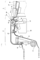
- Fig. 2 is a partial sectional view showing the structure of the printing unit and the affixing unit of the label affixer shown in Fig. 1 .
- the printing unit 3 includes a guide roller 31 for guiding the sheet 6 supplied by the supply unit 2, a label sensor 32 for detecting the position of a label on the sheet 6 inserted into the printing unit 3, a platen roller 33 that is driven to rotate by a stepping motor via a gear or a belt in order to convey the sheet 6, a thermal head 34 that opposes the platen roller 33 via the sheet 6 and performs printing onto the label, a head support 35 for supporting the thermal head 34, a head support frame 36 to which the head support 35 is attached rotatably, a head opening/closing lever 37 for opening and closing the head support 35 relative to the platen roller 33, a label peeling member 38 for peeling the label from the backing sheet, and a roller 39 for leading the backing sheet to the backing sheet winding unit 5.
- the thermal head 34 includes a collection of minute heat generators that generate heat when a current is caused to flow through the heat generators.
- a voltage is applied to the heat generators while the sheet is sandwiched between the platen roller 33 and the thermal head 34, causing a current to flow through the heat generators such that the heat generators generate heat.
- Printing is then performed onto the label by subjecting a thermal color development layer provided on the surface of the label to color development.
- Rotation of the platen roller 33 and backing sheet winding unit 5 is controlled on the basis of the label position detected by the label sensor 32.
- the platen roller 33 and the backing sheet winding unit 5 are rotated by a plurality of stepping motors, not shown in the drawing, the sheet 6 is conveyed from the supply unit 2 to the printing unit 3. Printing is then performed on the label by the thermal head 34, whereupon the backing sheet is wound by the backing sheet winding unit 5.
- the sheet 6 conveyed by the platen roller 33 and the backing sheet winding unit 5 is folded back by a tip end of the label peeling member 38 so as to bend greatly, and therefore, when the sheet 6 passes the bent portion, the label is peeled away from the backing sheet.
- the affixing unit 4 includes an air blasting pipe 45 in the suction position of the suction plate 41 to assist suction of the label by the suction plate 41.
- the air blasting pipe 45 includes a pipe main body having a parallel axis to an edge direction of the label peeling member 38, and a plurality of blasting holes for blasting air in the axial direction are formed in the pipe main body.
- the air blasting pipe 45 is positioned near the edge of the label peeling member 38 and on the outer side of the folded backing sheet in order to blast air toward the suction plate 41 side from the rear side (affixing surface side) of the label peeled away by the label peeling member 38.
- the air blasting pipe 45 prevents the label peeled away by the label peeling member 38 from sagging downward due to gravity, and therefore assists in ensuring that the suction plate 41 aspirates the label securely.
- the air blasting pipe 45 is provided on a support member extending from the casing so as to be capable of moving between two positions, namely a blasting position A for blasting air in a position near the edge of the label peeling member 38 and a removed position B removed from the label peeling member 38.
- One end of the air blasting pipe 45 is held by a holding body 46.
- the holding body 46 is formed with a sliding hole having an axis that aligns with the movement direction, and a guide shaft 47 is provided in the support member via an attachment member.
- the guide shaft 47 By inserting the guide shaft 47 into the sliding hole such that the sliding hole is free to slide, the holding body 46 is supported to be free to slide relative to the guide shaft 47, and as a result, the air blasting pipe 45 is supported movably on the supporting member.
- an angle of incline of the guide shaft 47 is determined such that the air blasting pipe 45 can advance and retreat in a direction that intersects a suction surface of the suction plate 41 at an incline.
- the removed position B of the air blasting pipe 45 is set in the vicinity of the suction surface of the suction plate 41 such that when the backing sheet is mounted, the air blasting pipe 45 is positioned on the outside of a label temporary adhesion-side surface of the backing sheet projecting from the label peeling member 38.
- a pair of feed rollers may be provided in opposing positions on either side of the sheet 6 on a downstream side of the conveyance direction near the label sensor 32 such that automatic control can be performed to rotate the feed rollers by a predetermined amount and move the air blasting pipe 45 to the removed position B when the tip end of the sheet 6 is detected by the label sensor 32 during sheet setting.
- the label peeled away by the label peeling member 38 is guided to the suction plate 41 side by air that is blasted onto the lower side of the label by the air blasting pipe 45, and as a result, the label is aspirated by the suction plate 41.
- the suction plate 41 is moved to an affixing position by the air cylinder 42, whereupon the suction plate 41 is brought into contact with the affixing subject body via the label such that the label is affixed to the affixing subject body.
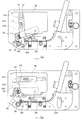
- Fig. 3 is a side view showing an opening/closing operation performed on the head support shown in Fig. 2 .
- the head support 35 is attached to the head support frame 36, which is fixed to the casing of the label affixer, to be capable of rotating about a head support shaft 351
- the head opening/closing lever 37 is attached to the head support frame 36 to be capable of rotating about a lever shaft 371.
- a cam holder 373 that rotates in conjunction with the head opening/closing lever 37 is attached to the lever shaft 371.
- a recess portion is formed in the cam holder 373, and a coil spring 374 and a cam 375 are inserted into the recess portion.
- the cam holder 373, coil spring 374, and cam 375 constitute a cam mechanism for positioning the head support 35.
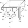
- Fig. 4 is a perspective view showing the head opening/closing lever and cam mechanism shown in Fig. 3 .
- the head support frame 36 is formed with a set of shaft holes 36a into which the head support shaft 351 ( Fig. 3 ) is inserted, and a set of shaft holes 36b into which the lever shaft 371 is inserted.
- Two cam holders 373 are attached to the lever shaft 371, and the coil spring 374 and cam 375 are inserted into the recess portion in each cam holder 373.
- the cam 375 is provided to be capable of sliding within the recess portion in the cam holder 373, and the cam 375 is held by a biasing force of the coil spring 374 so that it does not fly out of the recess portion in the cam holder 373.
- Fig. 3A shows a state in which the head support 35 is closed and the thermal head 34 is pressed against the platen roller 33 side.
- a hook 372 provided on the tip end of the head opening/closing lever 37 is locked onto a fixed shaft 331 provided in the vicinity of the platen roller 33.
- the cam 375 biases the head support 35 to the platen roller 33 side using an expansion force of the coil spring 374.
- Fig. 3B shows a state in which the head support 35 is open such that the thermal head 34 is removed from the platen roller 33 side.
- the cam holder 373 rotates in conjunction with the head opening/closing lever 37, thereby releasing the pressing contact of the cam 375, and as a result, the head support 35 rotates upward due to an action of a separating spring 353 to be described below such that the thermal head 34 separates from the platen roller 33.
- the thermal head 34 can be replaced easily by removing a part of the head support 35.
- Fig. 5 is an exploded perspective view showing a head support mechanism for supporting the thermal head.
- the head support 35 shown in Fig. 3 is attached rotatably to the head support frame 36 shown in Fig. 5A .
- the head support 35 is constituted by the head support shaft 351 shown in Fig. 5B , a head support upper portion (first head support member) 352 and a set of separating springs 353 shown in Fig. 5C , a head support lower portion (second head support member) 354 shown in Fig. 5D , an eccentric shaft 355 shown in Fig. 5E , and so on.
- the head support upper portion 352 is formed with a set of shaft holes (elongated holes) 352a into which the head support shaft 351 is inserted, a set of shaft holes 352b into which the eccentric shaft 355 is inserted, a set of screw holes 352c, and an engaging piece 352d that engages with one end of the separating spring 353.
- the head support upper portion 352 is attached to the inner side of the head support frame 36 by the head support shaft 351, and is capable of rotating relative to the head support frame 36 about the head support shaft 351.
- the set of separating springs 353 is inserted into the head support shaft 351 between the head support upper portion 352 and the head support frame 36. One end of the separating spring 353 engages with the engaging piece 352d of the head support upper portion 352 while the other end of the separating spring 353 is fixed to the casing, and therefore force oriented away from the platen roller (upward) is applied to the head support upper portion 352.
- the head support lower portion 354 is formed with a set of grooves 354a into which the head support shaft 351 is inserted, and a set of grooves 354b into which the eccentric shaft 355 is inserted.
- the thermal head 34 shown in Fig. 5F is attached to the head support lower portion 354 by a screw.
- the eccentric shaft 355 shown in Fig. 5E is inserted into the set of shaft holes 352b formed in the head support upper portion 352.
- One end of the eccentric shaft 355 is supported rotatably by a bearing member 358.
- a coil spring 356 is inserted into this end, and a ring 357 is fixed to the end.
- the bearing member 358 is fixed to the head support upper portion 352 by inserting a screw 359 into a screw hole 352c formed in the head support upper portion 352 via a screw hole 358a.
- a fixing plate 360 and an adjustment knob 361 are attached to the other end of the eccentric shaft 355.
- the eccentric shaft 355 is capable of rotating relative to the head support upper portion 352 and moving parallel to an axial direction, and is biased to the left side of the drawing by the expansion force of the coil spring 356. By pulling the adjustment knob 361, the eccentric shaft 355 can be moved to the right side of the drawing.
- the adjustment knob 361 rotates together with the eccentric shaft 355 and is used to adjust the position of the thermal head 34 relative to the platen roller.
- the fixing plate 360 rotates together with the eccentric shaft 355 and is used to fix the position of the thermal head 34 by inserting a screw 362 into the screw hole 352c formed in the head support upper portion 352 via a U-shaped hole formed in the fixing plate 360.
- Figs. 5A to 5D the position of the head support shaft 351 following assembly of the head support mechanism is indicated by a dot-dash line A-A'. Further, in Figs. 5C to 5E , the position of the eccentric shaft 355 following assembly of the head support mechanism is indicated by a dot-dash line B-B'.
- the grooves 354a in the head support lower portion 354 engage with the head support shaft 351 and the grooves 354b in the head support lower portion 354 engage with the eccentric shaft 355.
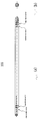
- Fig. 6 is a view showing in detail the shape of the eccentric shaft shown in Fig. 5E .
- Fig. 6A is a front view thereof
- Fig. 6B is a side view thereof.
- the eccentric shaft 355 includes a large diameter portion having a comparatively large radius and a small diameter portion having a smaller radius than the large diameter portion. The respective central axes of the large diameter portion and the small diameter portion are different.
- Fig. 7 is a view showing a state in which the eccentric shaft is inserted into the head support upper portion, Fig. 7A showing a state in which the head support lower portion and the head support upper portion are attached, and Fig. 7B showing a state in which the head support lower portion is removed from the head support upper portion 352.
- the eccentric shaft 355 is biased to the left side of the drawing by the coil spring 356.
- the head support upper portion 352 contacts the small diameter portion (left side of the drawing) and the large diameter portion (right side of the drawing) of the eccentric shaft 355 by the set of shaft holes 352b ( Fig. 5C ), while the head support lower portion 354 contacts the small diameter portion of the eccentric shaft 355 by the set of grooves 354b ( Fig. 5D ).
- the operator loosens the screw 362 and turns the adjustment knob 361 to rotate the eccentric shaft 355, whereby the eccentric shaft 355 rotates about the central axis of the small diameter portion (left side of the drawing) and the central axis of the large diameter portion (right side of the drawing).
- the eccentric shaft 355 rotates, the head support lower portion 354 slides in a front-rear direction relative to the head support upper portion 352 due to the offset between the large diameter portion and the small diameter portion, and thus the front-rear position of the thermal head 34 can be adjusted.
- the operator then tightens the screw 362 such that the angle of the eccentric shaft 355 is fixed by the fixing plate 360, thereby fixing the position of the thermal head 34.
- the operator pulls the adjustment knob 361 to increase a distance C between the head support upper portion 352 and the large diameter portion (the left side of the drawing) of the eccentric shaft 355, as shown in Fig. 7B .
- the grooves 354a ( Fig. 5D ) in the head support lower portion 354 are separated from the head support shaft 351, and as a result, the head support lower portion 354 can be removed from the head support upper portion 352.
- the thermal head 34 can be replaced easily.
Landscapes
- Electronic Switches (AREA)
- Common Mechanisms (AREA)
- Handling Of Sheets (AREA)
- Dot-Matrix Printers And Others (AREA)
- Printers Or Recording Devices Using Electromagnetic And Radiation Means (AREA)
Abstract
Description
- The present invention relates to a printer such as a label printer for conveying a label continuous body in which labels are temporarily adhered to a backing sheet and performing printing on the labels.
- In a label printer, a label continuous body (also referred to hereafter as a "sheet") in which labels of a predetermined length are temporarily adhered to an elongated strip-form backing sheet (separator) at constant intervals is used as a printing medium, for example. The sheet is conveyed by a platen roller, and printing is performed on the labels using a heat generator of a thermal head provided on the opposite side of the sheet to the platen roller.
- When the relative positions of the heat generator of the thermal head and the platen roller are different at this time, the printing quality deteriorates. Hence, the relative positions of the platen roller and the thermal head must be aligned accurately. Further, the thermal head is an expendable item, and therefore, the thermal head must be replaced when a part of the heat generator breaks down due to a disconnection or the like.
- However, in a conventional label printer, a front-rear position of the thermal head (the front and rear of a parallel direction to a conveyance direction of the sheet) is adjusted by an operator by fixing the thermal head using left and right screws while viewing a printing sample, and therefore the adjustment operation takes time and leads to large irregularities and the like according to the operator. Moreover, to replace the thermal head, the left and right screws must be loosened, and therefore front-rear position adjustment must be performed again after the thermal head is replaced.
- As related art, Japanese Unexamined Patent Application Publication
2003-48335 Fig. 1 ) discloses a head attachment/detachment mechanism in which an expendable thermal head can be attached and detached easily in a thermal printer in order to replace the head. In this head attachment/detachment mechanism, a rotatable attachment/detachment lever is disposed on a head substrate side, and by rotating the attachment/detachment lever, a part of a head support plate is pressed such that the head substrate side slips out from the head support plate side against the frictional resistance of a fitting portion between a connector on the head support plate side and a connector on the head substrate side. Thus, the thermal head can be attached and detached through a simple operation to rotate the attachment/detachment lever. - According to Japanese Unexamined Patent Application Publication
2003-48335 - In consideration of the points described above, an object of the present invention is to provide a printer with which both position adjustment and attachment/detachment of a printing head can be performed easily.
- To solve the problems described above, a printer according to one aspect of the present invention includes: a platen roller that conveys a printing medium when driven to rotate by a motor provided in a casing; a printing head that performs printing on the printing medium when the printing medium is sandwiched between the printing head and the platen roller; a first head support member capable of rotating relative to the casing; a first shaft serving as a rotary axis of the first head support member; a second shaft that is attached to the first head support member to be capable of rotating and moving parallel to an axial direction, and includes a large diameter portion having a comparatively large radius and a small diameter portion having a smaller radius than the large diameter portion and a different central axis to the rotary axis; and a second head support member, to which the printing head is attached, and which is formed with a first set of grooves into which the first shaft is inserted and a second set of grooves into which the second shaft is inserted, moves in accordance with rotation of the second shaft, when attached to the first head support member, due to engagement between the first set of grooves and the first shaft and engagement between the second set of grooves and the small diameter portion of the second shaft, and can be removed from the first head support member by moving the second shaft parallel to the axial direction.
- According to the present invention, the position of the printing head can be adjusted by rotating the second shaft, and the printing head can be attached and detached by moving the second shaft parallel to the axial direction, and therefore both position adjustment and attachment/detachment of the printing head can be performed easily.
-
-
Fig. 1 is a perspective view showing in pattern form a label affixer according to an embodiment of the present invention; -
Fig. 2 is a partial sectional view showing the structure of a printing unit and an affixing unit of the label affixer shown inFig. 1 ; -
Fig. 3 is a side view showing an opening/closing operation performed on a head support shown inFig. 2 ; -
Fig. 4 is a perspective view showing a head opening/closing lever and a cam mechanism shown inFig. 3 ; -
Fig. 5 is an exploded perspective view showing a head support mechanism for supporting a thermal head; -
Fig. 6 is a view showing in detail the shape of an eccentric shaft shown inFig. 5E ; and -
Fig. 7 is a view showing a state in which the eccentric shaft is inserted into a head support upper portion. - An embodiment of the present invention will be described in detail below with reference to the drawings. Note that identical reference symbols have been allocated to identical constitutional elements, and description thereof has been omitted.
- The present invention may be applied to a typical printer, but in the following embodiment, a case in which the present invention is applied to a label affixer for performing printing on a label and affixing the printed label to an affixing subject body such as cardboard will be described.
-
Fig. 1 is a perspective view showing in pattern form a label affixer according to an embodiment of the present invention. As shown inFig. 1 , the label affixer includes a casing 1, asheet supply unit 2 for supplying asheet 6 by rotatably holding a rolledsheet 6r formed by winding a label continuous body (sheet) in which labels are temporarily adhered to a backing sheet into a roll shape, aprinting unit 3 for performing printing onto the label part of thesheet 6 supplied by thesheet supply unit 2, an affixingunit 4 for affixing a label that has been peeled away from the backing sheet following printing to an affixing subject body such ascardboard 7, and a backingsheet winding unit 5 for winding the backing sheet from which the label has been peeled. - The affixing
unit 4 is provided with asuction plate 41 for aspirating a label that has been peeled away from the backing sheet by negatively pressurizing air, and anair cylinder 42 for moving thesuction plate 41 between a suction position in which thesuction plate 41 aspirates the label and an affixing position in which the label is brought into contact with and affixed to thecardboard 7 serving as the affixing subject body. Note that thesuction plate 41 is provided on the opposite side of aspring 44 to abase 43 so that shock generated when thesuction plate 41 contacts the affixing subject body via the label can be absorbed and an impact on the affixingunit 4 and the affixing subject body can be alleviated. -
Fig. 2 is a partial sectional view showing the structure of the printing unit and the affixing unit of the label affixer shown inFig. 1 . As shown inFig. 2 , theprinting unit 3 includes aguide roller 31 for guiding thesheet 6 supplied by thesupply unit 2, alabel sensor 32 for detecting the position of a label on thesheet 6 inserted into theprinting unit 3, aplaten roller 33 that is driven to rotate by a stepping motor via a gear or a belt in order to convey thesheet 6, athermal head 34 that opposes theplaten roller 33 via thesheet 6 and performs printing onto the label, ahead support 35 for supporting thethermal head 34, ahead support frame 36 to which thehead support 35 is attached rotatably, a head opening/closing lever 37 for opening and closing thehead support 35 relative to theplaten roller 33, alabel peeling member 38 for peeling the label from the backing sheet, and aroller 39 for leading the backing sheet to the backingsheet winding unit 5. - The
thermal head 34 includes a collection of minute heat generators that generate heat when a current is caused to flow through the heat generators. When printing is performed onto the label, a voltage is applied to the heat generators while the sheet is sandwiched between theplaten roller 33 and thethermal head 34, causing a current to flow through the heat generators such that the heat generators generate heat. Printing is then performed onto the label by subjecting a thermal color development layer provided on the surface of the label to color development. - Rotation of the
platen roller 33 and backingsheet winding unit 5 is controlled on the basis of the label position detected by thelabel sensor 32. When theplaten roller 33 and the backingsheet winding unit 5 are rotated by a plurality of stepping motors, not shown in the drawing, thesheet 6 is conveyed from thesupply unit 2 to theprinting unit 3. Printing is then performed on the label by thethermal head 34, whereupon the backing sheet is wound by the backingsheet winding unit 5. - The
sheet 6 conveyed by theplaten roller 33 and the backingsheet winding unit 5 is folded back by a tip end of thelabel peeling member 38 so as to bend greatly, and therefore, when thesheet 6 passes the bent portion, the label is peeled away from the backing sheet. The affixingunit 4 includes anair blasting pipe 45 in the suction position of thesuction plate 41 to assist suction of the label by thesuction plate 41. Theair blasting pipe 45 includes a pipe main body having a parallel axis to an edge direction of thelabel peeling member 38, and a plurality of blasting holes for blasting air in the axial direction are formed in the pipe main body. Theair blasting pipe 45 is positioned near the edge of thelabel peeling member 38 and on the outer side of the folded backing sheet in order to blast air toward thesuction plate 41 side from the rear side (affixing surface side) of the label peeled away by thelabel peeling member 38. By blasting air from the rear side of the label in a direction heading toward thesuction plate 41 side, theair blasting pipe 45 prevents the label peeled away by thelabel peeling member 38 from sagging downward due to gravity, and therefore assists in ensuring that thesuction plate 41 aspirates the label securely. - The
air blasting pipe 45 is provided on a support member extending from the casing so as to be capable of moving between two positions, namely a blasting position A for blasting air in a position near the edge of thelabel peeling member 38 and a removed position B removed from thelabel peeling member 38. One end of theair blasting pipe 45 is held by aholding body 46. Theholding body 46 is formed with a sliding hole having an axis that aligns with the movement direction, and aguide shaft 47 is provided in the support member via an attachment member. By inserting theguide shaft 47 into the sliding hole such that the sliding hole is free to slide, theholding body 46 is supported to be free to slide relative to theguide shaft 47, and as a result, theair blasting pipe 45 is supported movably on the supporting member. Further, an angle of incline of theguide shaft 47 is determined such that theair blasting pipe 45 can advance and retreat in a direction that intersects a suction surface of thesuction plate 41 at an incline. - Further, the removed position B of the
air blasting pipe 45 is set in the vicinity of the suction surface of thesuction plate 41 such that when the backing sheet is mounted, theair blasting pipe 45 is positioned on the outside of a label temporary adhesion-side surface of the backing sheet projecting from thelabel peeling member 38. By moving theair blasting pipe 45 to the removed position B, an operation space for laying thesheet 6 over thelabel peeling member 38 can be secured, and therefore an operation for replacing thesheet 6 can be performed easily. Further, a pair of feed rollers, not shown in the drawing, may be provided in opposing positions on either side of thesheet 6 on a downstream side of the conveyance direction near thelabel sensor 32 such that automatic control can be performed to rotate the feed rollers by a predetermined amount and move theair blasting pipe 45 to the removed position B when the tip end of thesheet 6 is detected by thelabel sensor 32 during sheet setting. - The label peeled away by the
label peeling member 38 is guided to thesuction plate 41 side by air that is blasted onto the lower side of the label by theair blasting pipe 45, and as a result, the label is aspirated by thesuction plate 41. Thesuction plate 41 is moved to an affixing position by theair cylinder 42, whereupon thesuction plate 41 is brought into contact with the affixing subject body via the label such that the label is affixed to the affixing subject body. -
Fig. 3 is a side view showing an opening/closing operation performed on the head support shown inFig. 2 . Thehead support 35 is attached to thehead support frame 36, which is fixed to the casing of the label affixer, to be capable of rotating about ahead support shaft 351, and the head opening/closing lever 37 is attached to thehead support frame 36 to be capable of rotating about alever shaft 371. Further, acam holder 373 that rotates in conjunction with the head opening/closing lever 37 is attached to thelever shaft 371. A recess portion is formed in thecam holder 373, and acoil spring 374 and acam 375 are inserted into the recess portion. Thecam holder 373,coil spring 374, andcam 375 constitute a cam mechanism for positioning thehead support 35. -
Fig. 4 is a perspective view showing the head opening/closing lever and cam mechanism shown inFig. 3 . As shown inFig. 4 , thehead support frame 36 is formed with a set ofshaft holes 36a into which the head support shaft 351 (Fig. 3 ) is inserted, and a set ofshaft holes 36b into which thelever shaft 371 is inserted. Twocam holders 373 are attached to thelever shaft 371, and thecoil spring 374 andcam 375 are inserted into the recess portion in eachcam holder 373. Thecam 375 is provided to be capable of sliding within the recess portion in thecam holder 373, and thecam 375 is held by a biasing force of thecoil spring 374 so that it does not fly out of the recess portion in thecam holder 373. - Referring back to
Fig. 3, Fig. 3A shows a state in which thehead support 35 is closed and thethermal head 34 is pressed against theplaten roller 33 side. Ahook 372 provided on the tip end of the head opening/closinglever 37 is locked onto a fixedshaft 331 provided in the vicinity of theplaten roller 33. Thecam 375 biases thehead support 35 to theplaten roller 33 side using an expansion force of thecoil spring 374. -
Fig. 3B shows a state in which thehead support 35 is open such that thethermal head 34 is removed from theplaten roller 33 side. When an operator rotates the head opening/closinglever 37 in a counter-clockwise direction of the drawing from the state shown inFig. 3A , thecam holder 373 rotates in conjunction with the head opening/closinglever 37, thereby releasing the pressing contact of thecam 375, and as a result, thehead support 35 rotates upward due to an action of a separatingspring 353 to be described below such that thethermal head 34 separates from theplaten roller 33. In this state, thethermal head 34 can be replaced easily by removing a part of thehead support 35. -
Fig. 5 is an exploded perspective view showing a head support mechanism for supporting the thermal head. Thehead support 35 shown inFig. 3 is attached rotatably to thehead support frame 36 shown inFig. 5A . Thehead support 35 is constituted by thehead support shaft 351 shown inFig. 5B , a head support upper portion (first head support member) 352 and a set of separatingsprings 353 shown inFig. 5C , a head support lower portion (second head support member) 354 shown inFig. 5D , aneccentric shaft 355 shown inFig. 5E , and so on. - As shown in
Fig. 5C , the head supportupper portion 352 is formed with a set of shaft holes (elongated holes) 352a into which thehead support shaft 351 is inserted, a set of shaft holes 352b into which theeccentric shaft 355 is inserted, a set ofscrew holes 352c, and anengaging piece 352d that engages with one end of the separatingspring 353. - The head support
upper portion 352 is attached to the inner side of thehead support frame 36 by thehead support shaft 351, and is capable of rotating relative to thehead support frame 36 about thehead support shaft 351. The set of separatingsprings 353 is inserted into thehead support shaft 351 between the head supportupper portion 352 and thehead support frame 36. One end of the separatingspring 353 engages with the engagingpiece 352d of the head supportupper portion 352 while the other end of the separatingspring 353 is fixed to the casing, and therefore force oriented away from the platen roller (upward) is applied to the head supportupper portion 352. - As shown in
Fig. 5D , the head supportlower portion 354 is formed with a set ofgrooves 354a into which thehead support shaft 351 is inserted, and a set ofgrooves 354b into which theeccentric shaft 355 is inserted. Thethermal head 34 shown inFig. 5F is attached to the head supportlower portion 354 by a screw. - The
eccentric shaft 355 shown inFig. 5E is inserted into the set ofshaft holes 352b formed in the head supportupper portion 352. One end of theeccentric shaft 355 is supported rotatably by a bearingmember 358. Acoil spring 356 is inserted into this end, and aring 357 is fixed to the end. The bearingmember 358 is fixed to the head supportupper portion 352 by inserting ascrew 359 into ascrew hole 352c formed in the head supportupper portion 352 via ascrew hole 358a. - A fixing
plate 360 and anadjustment knob 361 are attached to the other end of theeccentric shaft 355. Theeccentric shaft 355 is capable of rotating relative to the head supportupper portion 352 and moving parallel to an axial direction, and is biased to the left side of the drawing by the expansion force of thecoil spring 356. By pulling theadjustment knob 361, theeccentric shaft 355 can be moved to the right side of the drawing. - The
adjustment knob 361 rotates together with theeccentric shaft 355 and is used to adjust the position of thethermal head 34 relative to the platen roller. The fixingplate 360 rotates together with theeccentric shaft 355 and is used to fix the position of thethermal head 34 by inserting ascrew 362 into thescrew hole 352c formed in the head supportupper portion 352 via a U-shaped hole formed in the fixingplate 360. - In
Figs. 5A to 5D , the position of thehead support shaft 351 following assembly of the head support mechanism is indicated by a dot-dash line A-A'. Further, inFigs. 5C to 5E , the position of theeccentric shaft 355 following assembly of the head support mechanism is indicated by a dot-dash line B-B'. When the head supportlower portion 354 is attached to the inside of the head supportupper portion 352, thegrooves 354a in the head supportlower portion 354 engage with thehead support shaft 351 and thegrooves 354b in the head supportlower portion 354 engage with theeccentric shaft 355. -
Fig. 6 is a view showing in detail the shape of the eccentric shaft shown inFig. 5E .Fig. 6A is a front view thereof, andFig. 6B is a side view thereof. As shown inFig. 6 , theeccentric shaft 355 includes a large diameter portion having a comparatively large radius and a small diameter portion having a smaller radius than the large diameter portion. The respective central axes of the large diameter portion and the small diameter portion are different. -
Fig. 7 is a view showing a state in which the eccentric shaft is inserted into the head support upper portion,Fig. 7A showing a state in which the head support lower portion and the head support upper portion are attached, andFig. 7B showing a state in which the head support lower portion is removed from the head supportupper portion 352. - As shown in
Fig. 7A , theeccentric shaft 355 is biased to the left side of the drawing by thecoil spring 356. The head supportupper portion 352 contacts the small diameter portion (left side of the drawing) and the large diameter portion (right side of the drawing) of theeccentric shaft 355 by the set ofshaft holes 352b (Fig. 5C ), while the head supportlower portion 354 contacts the small diameter portion of theeccentric shaft 355 by the set ofgrooves 354b (Fig. 5D ). - To adjust the position of the
thermal head 34, the operator loosens thescrew 362 and turns theadjustment knob 361 to rotate theeccentric shaft 355, whereby theeccentric shaft 355 rotates about the central axis of the small diameter portion (left side of the drawing) and the central axis of the large diameter portion (right side of the drawing). When theeccentric shaft 355 rotates, the head supportlower portion 354 slides in a front-rear direction relative to the head supportupper portion 352 due to the offset between the large diameter portion and the small diameter portion, and thus the front-rear position of thethermal head 34 can be adjusted. The operator then tightens thescrew 362 such that the angle of theeccentric shaft 355 is fixed by the fixingplate 360, thereby fixing the position of thethermal head 34. - To replace the
thermal head 34, the operator pulls theadjustment knob 361 to increase a distance C between the head supportupper portion 352 and the large diameter portion (the left side of the drawing) of theeccentric shaft 355, as shown inFig. 7B . When the operator moves the head supportlower portion 354 towards him/herself from this state, thegrooves 354a (Fig. 5D ) in the head supportlower portion 354 are separated from thehead support shaft 351, and as a result, the head supportlower portion 354 can be removed from the head supportupper portion 352. Thus, thethermal head 34 can be replaced easily.
Claims (4)
- A printer comprising:a platen roller that conveys a printing medium when driven to rotate by a motor provided in a casing;a printing head that performs printing on said printing medium when said printing medium is sandwiched between said printing head and said platen roller;a first head support member capable of rotating relative to said casing;a first shaft serving as a rotary axis of said first head support member;a second shaft that is attached to said first head support member to be capable of rotating and moving parallel to an axial direction, and includes a large diameter portion having a comparatively large radius and a small diameter portion having a smaller radius than said large diameter portion and a different central axis to said rotary axis; anda second head support member, to which said printing head is attached, and which is formed with a first set of grooves into which said first shaft is inserted and a second set of grooves into which said second shaft is inserted, moves in accordance with rotation of said second shaft, when attached to said first head support member, due to engagement between said first set of grooves and said first shaft and engagement between said second set of grooves and said small diameter portion of said second shaft, and can be removed from said first head support member by moving said second shaft parallel to said axial direction.
- The printer according to claim 1, further comprising an adjustment knob that rotates together with said second shaft and is used to adjust a position of said printing head relative to said platen roller.
- The printer according to claim 1 or 2, further comprising a fixing plate that rotates together with said second shaft and is used to fix said position of said printing head relative to said platen roller.
- The printer according to any one of claims 1 to 3, further comprising:a support frame fixed to said casing, to which said first head support member is attached rotatably; anda head opening/closing lever that is attached rotatably to said support frame and operated to bias said first head support member to said platen roller side or separate said first head support member from said platen roller side.
Applications Claiming Priority (2)
| Application Number | Priority Date | Filing Date | Title |
|---|---|---|---|
| JP2007011971A JP2008173944A (en) | 2007-01-22 | 2007-01-22 | Printing device |
| PCT/JP2007/075072 WO2008090713A1 (en) | 2007-01-22 | 2007-12-27 | Character printing device |
Publications (4)
| Publication Number | Publication Date |
|---|---|
| EP2123463A1 true EP2123463A1 (en) | 2009-11-25 |
| EP2123463A4 EP2123463A4 (en) | 2010-02-24 |
| EP2123463B1 EP2123463B1 (en) | 2012-02-22 |
| EP2123463B8 EP2123463B8 (en) | 2012-04-11 |
Family
ID=39644288
Family Applications (1)
| Application Number | Title | Priority Date | Filing Date |
|---|---|---|---|
| EP07860294A Active EP2123463B8 (en) | 2007-01-22 | 2007-12-27 | Character printing device |
Country Status (5)
| Country | Link |
|---|---|
| US (1) | US8132906B2 (en) |
| EP (1) | EP2123463B8 (en) |
| JP (1) | JP2008173944A (en) |
| AT (1) | ATE546292T1 (en) |
| WO (1) | WO2008090713A1 (en) |
Families Citing this family (7)
| Publication number | Priority date | Publication date | Assignee | Title |
|---|---|---|---|---|
| JP2014008726A (en) * | 2012-07-02 | 2014-01-20 | Sato Holdings Corp | Printer |
| CN104708909B (en) * | 2015-03-31 | 2016-05-11 | 珠海正芯电子科技有限公司 | Label printing machine core |
| EP3562679B1 (en) * | 2016-12-30 | 2021-01-27 | Avery Dennison Retail Information Services, LLC | Printhead tangent adjustment mechanism |
| JP7178279B2 (en) * | 2019-01-29 | 2022-11-25 | 富士通コンポーネント株式会社 | printer device |
| BE1027644B1 (en) * | 2019-10-09 | 2021-05-11 | Phoenix Contact Gmbh & Co | Technique for marking a prolate object |
| US12015741B1 (en) * | 2023-05-25 | 2024-06-18 | Hand Held Products, Inc. | Printing apparatus and method of operating the same to generate an alert signal |
| US20260034816A1 (en) * | 2024-07-31 | 2026-02-05 | Brady Worldwide, Inc. | Printhead opening system and method |
Family Cites Families (9)
| Publication number | Priority date | Publication date | Assignee | Title |
|---|---|---|---|---|
| US5051009A (en) * | 1986-07-15 | 1991-09-24 | Monarch Marking Systems, Inc. | Printhead mount & cassette lock in a thermal printer |
| US5133611A (en) * | 1989-10-19 | 1992-07-28 | Canon Kabushiki Kaisha | Recording apparatus |
| DE4224533A1 (en) * | 1991-07-25 | 1993-01-28 | Kanzaki Paper Mfg Co Ltd | Thermal printer with improved head mounting - has head unit mounted on frame locating in pivot mounted housing that is located by lever and which applies spring force to head |
| JPH0546460U (en) * | 1991-11-28 | 1993-06-22 | 東京電気株式会社 | Thermal printer |
| JP3830578B2 (en) * | 1996-06-03 | 2006-10-04 | 株式会社新盛インダストリーズ | Thermal printer |
| JP2000071487A (en) * | 1998-09-01 | 2000-03-07 | Toshiba Tec Corp | Thermal printer |
| JP4999033B2 (en) | 2001-08-08 | 2012-08-15 | 株式会社新盛インダストリーズ | Thermal printer head attachment / detachment mechanism |
| JP2004262016A (en) * | 2003-02-28 | 2004-09-24 | Sato Corp | Thermal head attachment / detachment device for thermal printer |
| JP4537760B2 (en) * | 2004-05-12 | 2010-09-08 | 株式会社サトー | Printer device |
-
2007
- 2007-01-22 JP JP2007011971A patent/JP2008173944A/en active Pending
- 2007-12-27 US US12/524,062 patent/US8132906B2/en active Active
- 2007-12-27 EP EP07860294A patent/EP2123463B8/en active Active
- 2007-12-27 WO PCT/JP2007/075072 patent/WO2008090713A1/en not_active Ceased
- 2007-12-27 AT AT07860294T patent/ATE546292T1/en active
Also Published As
| Publication number | Publication date |
|---|---|
| JP2008173944A (en) | 2008-07-31 |
| EP2123463B1 (en) | 2012-02-22 |
| ATE546292T1 (en) | 2012-03-15 |
| US8132906B2 (en) | 2012-03-13 |
| WO2008090713A1 (en) | 2008-07-31 |
| EP2123463A4 (en) | 2010-02-24 |
| US20090315964A1 (en) | 2009-12-24 |
| EP2123463B8 (en) | 2012-04-11 |
Similar Documents
| Publication | Publication Date | Title |
|---|---|---|
| EP2123463B1 (en) | Character printing device | |
| CN107081969B (en) | Printer | |
| CN107323108B (en) | Paper feed, removing auxiliary device and printer | |
| JP4871946B2 (en) | Printer | |
| JP2003531786A (en) | Printing equipment | |
| JP3820927B2 (en) | Tape feeder | |
| JP4776023B2 (en) | Label printer | |
| US8087442B2 (en) | Adhesive sheet bonding device | |
| US20250236480A1 (en) | Roll support apparatus and recording apparatus | |
| JP2003057981A (en) | Fixing device | |
| EP1559564A2 (en) | Apparatus to guide label stock in a printer | |
| US11059311B2 (en) | Printer | |
| JP2005178309A (en) | Sensor support device for print media | |
| CN100436150C (en) | printer | |
| JP2004122495A (en) | Thermal printer positioning device for thermal printer | |
| JPH09226088A5 (en) | ||
| JP3408055B2 (en) | Fixing device | |
| JP2002036695A (en) | Printing equipment | |
| JP2007537904A (en) | Bookbinding machine | |
| JP2011148638A (en) | Label printer | |
| JP3410817B2 (en) | Printer device | |
| JP2011007977A (en) | Fixing device | |
| JPH04129699A (en) | Punching device for picture image forming device | |
| JP2024173559A (en) | Foil transfer device, sheet transport device and sheet support tool | |
| CN120229013A (en) | Printing assembly and printing device |
Legal Events
| Date | Code | Title | Description |
|---|---|---|---|
| PUAI | Public reference made under article 153(3) epc to a published international application that has entered the european phase |
Free format text: ORIGINAL CODE: 0009012 |
|
| 17P | Request for examination filed |
Effective date: 20090717 |
|
| AK | Designated contracting states |
Kind code of ref document: A1 Designated state(s): AT BE BG CH CY CZ DE DK EE ES FI FR GB GR HU IE IS IT LI LT LU LV MC MT NL PL PT RO SE SI SK TR |
|
| A4 | Supplementary search report drawn up and despatched |
Effective date: 20100127 |
|
| DAX | Request for extension of the european patent (deleted) | ||
| 17Q | First examination report despatched |
Effective date: 20100506 |
|
| GRAP | Despatch of communication of intention to grant a patent |
Free format text: ORIGINAL CODE: EPIDOSNIGR1 |
|
| GRAS | Grant fee paid |
Free format text: ORIGINAL CODE: EPIDOSNIGR3 |
|
| GRAA | (expected) grant |
Free format text: ORIGINAL CODE: 0009210 |
|
| AK | Designated contracting states |
Kind code of ref document: B1 Designated state(s): AT BE BG CH CY CZ DE DK EE ES FI FR GB GR HU IE IS IT LI LT LU LV MC MT NL PL PT RO SE SI SK TR |
|
| REG | Reference to a national code |
Ref country code: GB Ref legal event code: FG4D |
|
| REG | Reference to a national code |
Ref country code: CH Ref legal event code: EP |
|
| REG | Reference to a national code |
Ref country code: AT Ref legal event code: REF Ref document number: 546292 Country of ref document: AT Kind code of ref document: T Effective date: 20120315 |
|
| RAP2 | Party data changed (patent owner data changed or rights of a patent transferred) |
Owner name: SATO HOLDINGS KABUSHIKI KAISHA |
|
| REG | Reference to a national code |
Ref country code: IE Ref legal event code: FG4D |
|
| REG | Reference to a national code |
Ref country code: DE Ref legal event code: R096 Ref document number: 602007020922 Country of ref document: DE Effective date: 20120419 |
|
| REG | Reference to a national code |
Ref country code: NL Ref legal event code: VDEP Effective date: 20120222 |
|
| LTIE | Lt: invalidation of european patent or patent extension |
Effective date: 20120222 |
|
| PG25 | Lapsed in a contracting state [announced via postgrant information from national office to epo] |
Ref country code: LT Free format text: LAPSE BECAUSE OF FAILURE TO SUBMIT A TRANSLATION OF THE DESCRIPTION OR TO PAY THE FEE WITHIN THE PRESCRIBED TIME-LIMIT Effective date: 20120222 Ref country code: IS Free format text: LAPSE BECAUSE OF FAILURE TO SUBMIT A TRANSLATION OF THE DESCRIPTION OR TO PAY THE FEE WITHIN THE PRESCRIBED TIME-LIMIT Effective date: 20120622 Ref country code: NL Free format text: LAPSE BECAUSE OF FAILURE TO SUBMIT A TRANSLATION OF THE DESCRIPTION OR TO PAY THE FEE WITHIN THE PRESCRIBED TIME-LIMIT Effective date: 20120222 |
|
| PG25 | Lapsed in a contracting state [announced via postgrant information from national office to epo] |
Ref country code: PT Free format text: LAPSE BECAUSE OF FAILURE TO SUBMIT A TRANSLATION OF THE DESCRIPTION OR TO PAY THE FEE WITHIN THE PRESCRIBED TIME-LIMIT Effective date: 20120622 Ref country code: FI Free format text: LAPSE BECAUSE OF FAILURE TO SUBMIT A TRANSLATION OF THE DESCRIPTION OR TO PAY THE FEE WITHIN THE PRESCRIBED TIME-LIMIT Effective date: 20120222 Ref country code: GR Free format text: LAPSE BECAUSE OF FAILURE TO SUBMIT A TRANSLATION OF THE DESCRIPTION OR TO PAY THE FEE WITHIN THE PRESCRIBED TIME-LIMIT Effective date: 20120523 Ref country code: LV Free format text: LAPSE BECAUSE OF FAILURE TO SUBMIT A TRANSLATION OF THE DESCRIPTION OR TO PAY THE FEE WITHIN THE PRESCRIBED TIME-LIMIT Effective date: 20120222 Ref country code: BE Free format text: LAPSE BECAUSE OF FAILURE TO SUBMIT A TRANSLATION OF THE DESCRIPTION OR TO PAY THE FEE WITHIN THE PRESCRIBED TIME-LIMIT Effective date: 20120222 |
|
| PG25 | Lapsed in a contracting state [announced via postgrant information from national office to epo] |
Ref country code: CY Free format text: LAPSE BECAUSE OF FAILURE TO SUBMIT A TRANSLATION OF THE DESCRIPTION OR TO PAY THE FEE WITHIN THE PRESCRIBED TIME-LIMIT Effective date: 20120222 |
|
| PG25 | Lapsed in a contracting state [announced via postgrant information from national office to epo] |
Ref country code: EE Free format text: LAPSE BECAUSE OF FAILURE TO SUBMIT A TRANSLATION OF THE DESCRIPTION OR TO PAY THE FEE WITHIN THE PRESCRIBED TIME-LIMIT Effective date: 20120222 Ref country code: RO Free format text: LAPSE BECAUSE OF FAILURE TO SUBMIT A TRANSLATION OF THE DESCRIPTION OR TO PAY THE FEE WITHIN THE PRESCRIBED TIME-LIMIT Effective date: 20120222 Ref country code: DK Free format text: LAPSE BECAUSE OF FAILURE TO SUBMIT A TRANSLATION OF THE DESCRIPTION OR TO PAY THE FEE WITHIN THE PRESCRIBED TIME-LIMIT Effective date: 20120222 Ref country code: SI Free format text: LAPSE BECAUSE OF FAILURE TO SUBMIT A TRANSLATION OF THE DESCRIPTION OR TO PAY THE FEE WITHIN THE PRESCRIBED TIME-LIMIT Effective date: 20120222 Ref country code: SE Free format text: LAPSE BECAUSE OF FAILURE TO SUBMIT A TRANSLATION OF THE DESCRIPTION OR TO PAY THE FEE WITHIN THE PRESCRIBED TIME-LIMIT Effective date: 20120222 Ref country code: CZ Free format text: LAPSE BECAUSE OF FAILURE TO SUBMIT A TRANSLATION OF THE DESCRIPTION OR TO PAY THE FEE WITHIN THE PRESCRIBED TIME-LIMIT Effective date: 20120222 Ref country code: PL Free format text: LAPSE BECAUSE OF FAILURE TO SUBMIT A TRANSLATION OF THE DESCRIPTION OR TO PAY THE FEE WITHIN THE PRESCRIBED TIME-LIMIT Effective date: 20120222 |
|
| REG | Reference to a national code |
Ref country code: AT Ref legal event code: MK05 Ref document number: 546292 Country of ref document: AT Kind code of ref document: T Effective date: 20120222 |
|
| PG25 | Lapsed in a contracting state [announced via postgrant information from national office to epo] |
Ref country code: IT Free format text: LAPSE BECAUSE OF FAILURE TO SUBMIT A TRANSLATION OF THE DESCRIPTION OR TO PAY THE FEE WITHIN THE PRESCRIBED TIME-LIMIT Effective date: 20120222 Ref country code: SK Free format text: LAPSE BECAUSE OF FAILURE TO SUBMIT A TRANSLATION OF THE DESCRIPTION OR TO PAY THE FEE WITHIN THE PRESCRIBED TIME-LIMIT Effective date: 20120222 |
|
| PLBE | No opposition filed within time limit |
Free format text: ORIGINAL CODE: 0009261 |
|
| STAA | Information on the status of an ep patent application or granted ep patent |
Free format text: STATUS: NO OPPOSITION FILED WITHIN TIME LIMIT |
|
| 26N | No opposition filed |
Effective date: 20121123 |
|
| PG25 | Lapsed in a contracting state [announced via postgrant information from national office to epo] |
Ref country code: AT Free format text: LAPSE BECAUSE OF FAILURE TO SUBMIT A TRANSLATION OF THE DESCRIPTION OR TO PAY THE FEE WITHIN THE PRESCRIBED TIME-LIMIT Effective date: 20120222 |
|
| REG | Reference to a national code |
Ref country code: DE Ref legal event code: R097 Ref document number: 602007020922 Country of ref document: DE Effective date: 20121123 |
|
| PG25 | Lapsed in a contracting state [announced via postgrant information from national office to epo] |
Ref country code: ES Free format text: LAPSE BECAUSE OF FAILURE TO SUBMIT A TRANSLATION OF THE DESCRIPTION OR TO PAY THE FEE WITHIN THE PRESCRIBED TIME-LIMIT Effective date: 20120602 |
|
| PG25 | Lapsed in a contracting state [announced via postgrant information from national office to epo] |
Ref country code: MC Free format text: LAPSE BECAUSE OF NON-PAYMENT OF DUE FEES Effective date: 20121231 Ref country code: BG Free format text: LAPSE BECAUSE OF FAILURE TO SUBMIT A TRANSLATION OF THE DESCRIPTION OR TO PAY THE FEE WITHIN THE PRESCRIBED TIME-LIMIT Effective date: 20120522 |
|
| REG | Reference to a national code |
Ref country code: CH Ref legal event code: PL |
|
| REG | Reference to a national code |
Ref country code: IE Ref legal event code: MM4A |
|
| PG25 | Lapsed in a contracting state [announced via postgrant information from national office to epo] |
Ref country code: LI Free format text: LAPSE BECAUSE OF NON-PAYMENT OF DUE FEES Effective date: 20121231 Ref country code: CH Free format text: LAPSE BECAUSE OF NON-PAYMENT OF DUE FEES Effective date: 20121231 Ref country code: IE Free format text: LAPSE BECAUSE OF NON-PAYMENT OF DUE FEES Effective date: 20121227 |
|
| PG25 | Lapsed in a contracting state [announced via postgrant information from national office to epo] |
Ref country code: MT Free format text: LAPSE BECAUSE OF FAILURE TO SUBMIT A TRANSLATION OF THE DESCRIPTION OR TO PAY THE FEE WITHIN THE PRESCRIBED TIME-LIMIT Effective date: 20120222 |
|
| PG25 | Lapsed in a contracting state [announced via postgrant information from national office to epo] |
Ref country code: TR Free format text: LAPSE BECAUSE OF FAILURE TO SUBMIT A TRANSLATION OF THE DESCRIPTION OR TO PAY THE FEE WITHIN THE PRESCRIBED TIME-LIMIT Effective date: 20120222 |
|
| PG25 | Lapsed in a contracting state [announced via postgrant information from national office to epo] |
Ref country code: LU Free format text: LAPSE BECAUSE OF NON-PAYMENT OF DUE FEES Effective date: 20121227 |
|
| PG25 | Lapsed in a contracting state [announced via postgrant information from national office to epo] |
Ref country code: HU Free format text: LAPSE BECAUSE OF FAILURE TO SUBMIT A TRANSLATION OF THE DESCRIPTION OR TO PAY THE FEE WITHIN THE PRESCRIBED TIME-LIMIT Effective date: 20071227 |
|
| REG | Reference to a national code |
Ref country code: FR Ref legal event code: PLFP Year of fee payment: 9 |
|
| REG | Reference to a national code |
Ref country code: FR Ref legal event code: PLFP Year of fee payment: 10 |
|
| REG | Reference to a national code |
Ref country code: FR Ref legal event code: PLFP Year of fee payment: 11 |
|
| P01 | Opt-out of the competence of the unified patent court (upc) registered |
Effective date: 20230413 |
|
| PGFP | Annual fee paid to national office [announced via postgrant information from national office to epo] |
Ref country code: DE Payment date: 20241210 Year of fee payment: 18 |
|
| PGFP | Annual fee paid to national office [announced via postgrant information from national office to epo] |
Ref country code: GB Payment date: 20241224 Year of fee payment: 18 |
|
| PGFP | Annual fee paid to national office [announced via postgrant information from national office to epo] |
Ref country code: FR Payment date: 20241223 Year of fee payment: 18 |