EP2123315B1 - Device for collecting blood in an extracorporeal circuit comprising a venous blood reservoir and a cardiotomy reservoir - Google Patents
Device for collecting blood in an extracorporeal circuit comprising a venous blood reservoir and a cardiotomy reservoir Download PDFInfo
- Publication number
- EP2123315B1 EP2123315B1 EP09160458A EP09160458A EP2123315B1 EP 2123315 B1 EP2123315 B1 EP 2123315B1 EP 09160458 A EP09160458 A EP 09160458A EP 09160458 A EP09160458 A EP 09160458A EP 2123315 B1 EP2123315 B1 EP 2123315B1
- Authority
- EP
- European Patent Office
- Prior art keywords
- reservoir
- duct
- venous blood
- cardiotomy
- blood
- Prior art date
- Legal status (The legal status is an assumption and is not a legal conclusion. Google has not performed a legal analysis and makes no representation as to the accuracy of the status listed.)
- Not-in-force
Links
Images



Classifications
-
- A—HUMAN NECESSITIES
- A61—MEDICAL OR VETERINARY SCIENCE; HYGIENE
- A61M—DEVICES FOR INTRODUCING MEDIA INTO, OR ONTO, THE BODY; DEVICES FOR TRANSDUCING BODY MEDIA OR FOR TAKING MEDIA FROM THE BODY; DEVICES FOR PRODUCING OR ENDING SLEEP OR STUPOR
- A61M1/00—Suction or pumping devices for medical purposes; Devices for carrying-off, for treatment of, or for carrying-over, body-liquids; Drainage systems
- A61M1/36—Other treatment of blood in a by-pass of the natural circulatory system, e.g. temperature adaptation, irradiation ; Extra-corporeal blood circuits
- A61M1/3621—Extra-corporeal blood circuits
- A61M1/3627—Degassing devices; Buffer reservoirs; Drip chambers; Blood filters
-
- A—HUMAN NECESSITIES
- A61—MEDICAL OR VETERINARY SCIENCE; HYGIENE
- A61M—DEVICES FOR INTRODUCING MEDIA INTO, OR ONTO, THE BODY; DEVICES FOR TRANSDUCING BODY MEDIA OR FOR TAKING MEDIA FROM THE BODY; DEVICES FOR PRODUCING OR ENDING SLEEP OR STUPOR
- A61M1/00—Suction or pumping devices for medical purposes; Devices for carrying-off, for treatment of, or for carrying-over, body-liquids; Drainage systems
- A61M1/36—Other treatment of blood in a by-pass of the natural circulatory system, e.g. temperature adaptation, irradiation ; Extra-corporeal blood circuits
- A61M1/3621—Extra-corporeal blood circuits
- A61M1/3627—Degassing devices; Buffer reservoirs; Drip chambers; Blood filters
- A61M1/3632—Combined venous-cardiotomy reservoirs
Definitions
- the invention relates to device for collecting blood in an extracorporeal circuit which comprises a venous blood reservoir and a cardiotomy reservoir.
- extracorporeal blood circulation circuits that are activated during certain surgical procedures include, among others, a device that comprises two apparatuses shaped like interconnected containers, known respectively as “venous blood reservoir” and “cardiotomy reservoir”.
- the venous blood reservoir is provided with a coupling to a line for conveying the venous blood that arrives from the patient's heart and is aspirated by gravity or by way of a certain degree of vacuum that is created within the reservoir proper, and usually also with a coupling to a line for the conveyance of venous blood drawn from the aorta by means of a cannula known as "intracavitary vent", generally provided with a peristaltic pump; said reservoir is also provided with a connector for the outflow of blood toward the additional devices that are present in the extracorporeal circuit.
- the cardiotomy reservoir is provided with a coupling to a line for the conveyance of the blood drawn from the operating field, and said conveyance is provided by means of a peristaltic pump.
- the two devices are interconnected, but the methods for transferring blood from one apparatus to the other occur in ways that are not entirely satisfactory.
- US 6,017,493 discloses a device as defined in the preamble of claim 1.
- the aim of the present invention is therefore to provide a device of the described type in which the ways of transferring blood from one of the apparatuses that compose said device to the other are optimized, and which further allows to eliminate the pumps provided on the lines for conveying blood thereto.
- a device for collecting blood in an extracorporeal circuit comprising a venous blood reservoir and a cardiotomy reservoir, characterized in that it comprises the features given in the appended claims.
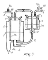
- the reference numeral 1 generally designates the device according to the invention, which comprises a venous blood reservoir 2 and a cardiotomy reservoir 3.
- the venous blood reservoir 2 which comprises in a known manner within itself a filtering mass 2a, is provided with couplings 4 and 5, which are connected to lines that convey venous blood from a patient, drawing it respectively from the heart and from the aorta by means of the intracavitary vent, and is further provided with a connector 6 for the outflow of the blood toward additional apparatuses, such as an oxygenation device, comprised within the extracorporeal circuit.
- the cardiotomy reservoir 3 which comprises in a known manner within itself a filtering mass 3 a, is provided with a coupling 7 connected to a line for conveying blood collected from the operating field.
- the venous blood reservoir 2 and the cardiotomy reservoir 3 are connected to respective independent lines, designated respectively by the reference numerals 8 and 9, which lead to vacuum sources that are adapted to determine different degrees of vacuum in such apparatuses, the degree of vacuum related to the venous blood reservoir 2: merely by way of indication, as typical a value of the degree of vacuum equal to 0.13 bars in the cardiotomy reservoir and equal to 0.04 bars in the venous blood reservoir can be indicated, these values being such as to ensure respectively an effective removal of blood from the operating field without the aid of any pump, and a nontraumatic treatment of the venous blood drawn from the patient.
- Line 9 in particular, and preferably also line 8 have a connection to the atmosphere, designated by the reference numeral 8a for the line 8 and 9a for the line 9, which is provided with removable blockage means, designated respectively by the reference numerals 8b and 9b, provided by means of a clamp-like apparatus that is known in the field as "clamp".
- the device is provided with means for mutual connection of the venous blood reservoir and of the cardiotomy reservoir which comprise a first duct 10 and a second duct 11.
- the first duct 10 is connected to said apparatuses substantially at the bottom: it in fact leads, at one end, to a connector 4a that extends from the bottom of the venous blood reservoir to accommodate the coupling 4, and is inserted, at the other end, in a valve 12 located at the bottom of the cardiotomy reservoir 3.
- the second duct 11, provided with removable blockage means constituted by a clamp 11a, is connected at one end to an upper lid 2b of the venous blood reservoir 2 and leads out at the other end proximate to the bottom of the cardiotomy reservoir 3, and more precisely at the valve 12; the valve 12 can move between the position visible in Figures 1 and 4 for simultaneous blockage of the duct 10 and opening of the end of the duct 11, and the position visible in Figures 2 and 3 of simultaneous opening of the duct 10 and of blockage of the end of the duct 11.
- a one-way safety valve can be provided to prevent the occurrence of abnormal vacuum values within the two apparatuses.
- This operating condition is particularly advantageous: if the clamp 11a is in fact left open after the cardiotomy reservoir has achieved complete emptying, air reaches the reservoir 2, but its entry from above excludes any possibility of mixing with the blood, which therefore remains entirely free from traumas.
Landscapes
- Health & Medical Sciences (AREA)
- Heart & Thoracic Surgery (AREA)
- Vascular Medicine (AREA)
- Life Sciences & Earth Sciences (AREA)
- Engineering & Computer Science (AREA)
- Anesthesiology (AREA)
- Biomedical Technology (AREA)
- Hematology (AREA)
- Cardiology (AREA)
- Animal Behavior & Ethology (AREA)
- General Health & Medical Sciences (AREA)
- Public Health (AREA)
- Veterinary Medicine (AREA)
- External Artificial Organs (AREA)
- Measurement Of The Respiration, Hearing Ability, Form, And Blood Characteristics Of Living Organisms (AREA)
- Measuring Pulse, Heart Rate, Blood Pressure Or Blood Flow (AREA)
Description
- The invention relates to device for collecting blood in an extracorporeal circuit which comprises a venous blood reservoir and a cardiotomy reservoir.
- It is known that the extracorporeal blood circulation circuits that are activated during certain surgical procedures include, among others, a device that comprises two apparatuses shaped like interconnected containers, known respectively as "venous blood reservoir" and "cardiotomy reservoir".
- The venous blood reservoir is provided with a coupling to a line for conveying the venous blood that arrives from the patient's heart and is aspirated by gravity or by way of a certain degree of vacuum that is created within the reservoir proper, and usually also with a coupling to a line for the conveyance of venous blood drawn from the aorta by means of a cannula known as "intracavitary vent", generally provided with a peristaltic pump; said reservoir is also provided with a connector for the outflow of blood toward the additional devices that are present in the extracorporeal circuit.
- The cardiotomy reservoir is provided with a coupling to a line for the conveyance of the blood drawn from the operating field, and said conveyance is provided by means of a peristaltic pump.
- As mentioned, the two devices are interconnected, but the methods for transferring blood from one apparatus to the other occur in ways that are not entirely satisfactory.
-
US 6,017,493 discloses a device as defined in the preamble of claim 1. - The aim of the present invention is therefore to provide a device of the described type in which the ways of transferring blood from one of the apparatuses that compose said device to the other are optimized, and which further allows to eliminate the pumps provided on the lines for conveying blood thereto.
- This aim is achieved by a device for collecting blood in an extracorporeal circuit comprising a venous blood reservoir and a cardiotomy reservoir, characterized in that it comprises the features given in the appended claims.
- Further characteristics and advantages will become better apparent from the description of a preferred but not exclusive embodiment of the device according to the invention, illustrated by way of non-limiting example in the accompanying drawings, wherein:
-
Figure 1 is a schematic view of the device according to the invention in normal operating conditions; -
Figures 2 ,3 ,4 are views of the device in different situations of transfer of blood from one of the apparatuses comprised within the device to the other, as will become better apparent hereinafter. - With reference to the figures, the reference numeral 1 generally designates the device according to the invention, which comprises a
venous blood reservoir 2 and acardiotomy reservoir 3. - The
venous blood reservoir 2, which comprises in a known manner within itself a filtering mass 2a, is provided withcouplings connector 6 for the outflow of the blood toward additional apparatuses, such as an oxygenation device, comprised within the extracorporeal circuit. - The
cardiotomy reservoir 3, which comprises in a known manner within itself a filtering mass 3 a, is provided with acoupling 7 connected to a line for conveying blood collected from the operating field. - The
venous blood reservoir 2 and thecardiotomy reservoir 3 are connected to respective independent lines, designated respectively by thereference numerals -
Line 9 in particular, and preferably alsoline 8, have a connection to the atmosphere, designated by thereference numeral 8a for theline 8 and 9a for theline 9, which is provided with removable blockage means, designated respectively by thereference numerals 8b and 9b, provided by means of a clamp-like apparatus that is known in the field as "clamp". - The device is provided with means for mutual connection of the venous blood reservoir and of the cardiotomy reservoir which comprise a
first duct 10 and asecond duct 11. - The
first duct 10 is connected to said apparatuses substantially at the bottom: it in fact leads, at one end, to a connector 4a that extends from the bottom of the venous blood reservoir to accommodate thecoupling 4, and is inserted, at the other end, in avalve 12 located at the bottom of thecardiotomy reservoir 3. - The
second duct 11, provided with removable blockage means constituted by aclamp 11a, is connected at one end to an upper lid 2b of thevenous blood reservoir 2 and leads out at the other end proximate to the bottom of thecardiotomy reservoir 3, and more precisely at thevalve 12; thevalve 12 can move between the position visible inFigures 1 and4 for simultaneous blockage of theduct 10 and opening of the end of theduct 11, and the position visible inFigures 2 and3 of simultaneous opening of theduct 10 and of blockage of the end of theduct 11. - On the lines connected to the
couplings - In normal operating conditions, shown in
Figure 1 , theclamp 11a is closed and thevalve 12 is in a position for blocking theduct 10; the venous blood arrives from the patient to thevenous blood reservoir 2 by means of thecouplings cardiotomy reservoir 3 by means of thecoupling 7, all as indicated by the arrows in the figure, thanks to the appropriate degrees of vacuum that are present in said apparatuses. - If the need arises to transfer blood from the
venous reservoir 2 to thecardiotomy reservoir 3, it is sufficient to move thevalve 12 to the position ofFigure 2 , leaving theclamp 11a closed: the blood, following the arrows in the figure, passes from thevenous reservoir 2 to thecardiotomy reservoir 3, flowing along theduct 10, attracted by the higher degree of vacuum. - If vice versa it is necessary to transfer blood from the
cardiotomy reservoir 3 to thevenous reservoir 2, it is necessary to perform a first operation, which consists in opening the clamp 9b, obtaining the effect of bringing thecardiotomy reservoir 3 to atmospheric pressure, and at this point two possibilities arise. - It is in fact possible to work as indicated in
Figure 3 : leaving theclamp 11a closed, thevalve 12 is moved to the open position of theduct 10 and thus the blood passes from thecardiotomy reservoir 3 at atmospheric pressure to thereservoir 2, in which there is a certain degree of vacuum, following theduct 10 as shown by the arrows in the figure. - However, the operating possibility shown in
Figure 4 is also offered, in which theclamp 11a is opened and thevalve 12 is moved to the position for blocking the duct 10: thanks to the fact that the blood is drawn from thecardiotomy reservoir 3 at atmospheric pressure at the bottom, the blood passes into thevenous blood reservoir 2, which is in vacuum, following theduct 11 along the arrows shown in the figure until the cardiotomy reservoir is emptied completely. - This operating condition is particularly advantageous: if the
clamp 11a is in fact left open after the cardiotomy reservoir has achieved complete emptying, air reaches thereservoir 2, but its entry from above excludes any possibility of mixing with the blood, which therefore remains entirely free from traumas. - The described invention is susceptible of numerous modifications and variations, as far as these are within the scope of the appended claims; all the details may further be replaced with other technically equivalent elements.
- Where technical features mentioned in any claim are followed by reference signs, those reference signs have been included for the sole purpose of increasing the intelligibility of the claims and accordingly, such reference signs do not have any limiting effect on the interpretation of each element identified by way of example by such reference signs.
Claims (5)
- A device (1) for collecting blood in an extracorporeal circuit comprising a venous blood reservoir (2) and a cardiotomy reservoir (3), said venous blood reservoir (2) and said cardiotomy reservoir (3) being interconnected and being provided with couplings (4, 5) respectively to at least one line for conveying venous blood from the patient and to a line for conveying blood collected from the operating field, said venous blood reservoir (2) being further provided with a connector (6) for the outflow of the blood toward additional apparatuses comprised within said extracorporeal circuit, said venous blood reservoir (2) and said cardiotomy reservoir (3) being connected to respective independent lines (8, 9) that reach vacuum sources and having, at least as regards the line (9) related to the cardiotomy reservoir (3), a connection (9a) to the atmosphere provided with removable blocking means (9b), there being also means for the mutual connection of the venous blood reservoir (2) and the cardiotomy reservoir (3) which comprise a first duct (10) that is connected at its ends to said apparatuses at the bottom, characterized in that said vacuum sources are adapted to determine different degrees of vacuum in said apparatuses, the degree of vacuum related to the cardiotomy reservoir (3) being higher than the degree of vacuum related to the venous blood reservoir (2), said first duct (10) being provided with removable blocking means (12) and there being a second duct (11), provided with removable blocking means (11a), which is connected at one end to the upper lid (2b) of the venous blood reservoir (2) and leads at the other end proximate to the bottom of the cardiotomy reservoir (3).
- The device according to claim 1, characterized in that the first duct (10) is provided with removable blocking means (12), which comprise a valve (12) located at the end that is connected to the bottom of the cardiotomy reservoir (3).
- The device according to claim 1, characterized in that the first duct (10) is provided with removable blockage means (12), which comprise a valve (12) located at the end that is connected to the bottom of the cardiotomy reservoir (3), which can move between a position for simultaneous blocking of said first duct (10) and opening of the end of the second duct (11) that leads into the cardiotomy reservoir (3), and a position for simultaneous opening of said first duct (10) and for blocking said end of the second duct (11).
- The device according to one or more of the preceding claims, characterized in that the removable means (11a) for blocking the second duct (11) comprise a clamp (11a).
- The device according to one or more of the preceding claims, comprising a venous blood reservoir (2) which has, in addition to a first coupling (4, 5, 7) to a line for conveying venous blood from the heart of a patient, a second coupling to a line for conveying blood drawn by means of an intracavitary vent, characterized by the presence of a one-way and safety valve on the lines connected respectively to said second coupling, to the coupling (7) provided on the cardiotomy reservoir (3) and to the output connector (6) of the venous blood reservoir (2).
Applications Claiming Priority (1)
| Application Number | Priority Date | Filing Date | Title |
|---|---|---|---|
| IT000946A ITMI20080946A1 (en) | 2008-05-22 | 2008-05-22 | BLOOD COLLECTION DEVICE IN THE EXTRACORPORAL CIRCUIT INCLUDING VENOUS AND CARDIOTOME RESERVE. |
Publications (3)
| Publication Number | Publication Date |
|---|---|
| EP2123315A1 EP2123315A1 (en) | 2009-11-25 |
| EP2123315A8 EP2123315A8 (en) | 2010-04-21 |
| EP2123315B1 true EP2123315B1 (en) | 2012-10-31 |
Family
ID=40302806
Family Applications (1)
| Application Number | Title | Priority Date | Filing Date |
|---|---|---|---|
| EP09160458A Not-in-force EP2123315B1 (en) | 2008-05-22 | 2009-05-18 | Device for collecting blood in an extracorporeal circuit comprising a venous blood reservoir and a cardiotomy reservoir |
Country Status (2)
| Country | Link |
|---|---|
| EP (1) | EP2123315B1 (en) |
| IT (1) | ITMI20080946A1 (en) |
Cited By (1)
| Publication number | Priority date | Publication date | Assignee | Title |
|---|---|---|---|---|
| WO2022202974A1 (en) | 2021-03-26 | 2022-09-29 | 株式会社ジェイ・エム・エス | Blood circulation circuit |
Families Citing this family (2)
| Publication number | Priority date | Publication date | Assignee | Title |
|---|---|---|---|---|
| CN103877632B (en) * | 2014-04-14 | 2016-03-23 | 东莞科威医疗器械有限公司 | Two-chamber storage blood device |
| CN104096275A (en) * | 2014-07-18 | 2014-10-15 | 杨国锋 | Post-operation auto-blood recycling device |
Family Cites Families (3)
| Publication number | Priority date | Publication date | Assignee | Title |
|---|---|---|---|---|
| US5158533A (en) * | 1991-03-26 | 1992-10-27 | Gish Biomedical, Inc. | Combined cardiotomy/venous/pleural drainage autotransfusion unit with filter and integral manometer and water seal |
| US5823986A (en) * | 1995-02-08 | 1998-10-20 | Medtronic, Inc. | Perfusion system |
| US6017493A (en) | 1997-09-26 | 2000-01-25 | Baxter International Inc. | Vacuum-assisted venous drainage reservoir for CPB systems |
-
2008
- 2008-05-22 IT IT000946A patent/ITMI20080946A1/en unknown
-
2009
- 2009-05-18 EP EP09160458A patent/EP2123315B1/en not_active Not-in-force
Cited By (1)
| Publication number | Priority date | Publication date | Assignee | Title |
|---|---|---|---|---|
| WO2022202974A1 (en) | 2021-03-26 | 2022-09-29 | 株式会社ジェイ・エム・エス | Blood circulation circuit |
Also Published As
| Publication number | Publication date |
|---|---|
| EP2123315A1 (en) | 2009-11-25 |
| ITMI20080946A1 (en) | 2009-11-23 |
| EP2123315A8 (en) | 2010-04-21 |
Similar Documents
| Publication | Publication Date | Title |
|---|---|---|
| KR101148716B1 (en) | Method and apparatus for priming an extracorporeal blood circuit | |
| KR101802833B1 (en) | Device and method for identifying couplings between two system components | |
| CN101400387B (en) | Method for at least partially draining an extracorporeal blood flow and haemodialysis device for use with said method | |
| US11724019B2 (en) | Method and devices for emptying an effluent bag after blood treatment | |
| EP2123315B1 (en) | Device for collecting blood in an extracorporeal circuit comprising a venous blood reservoir and a cardiotomy reservoir | |
| US20070009378A1 (en) | Device for handling blood in extracorporeal blood circulation | |
| US10617798B2 (en) | Device for aspirating and transferring blood | |
| JP2023022218A (en) | Blood spill cleaning system and method | |
| US20050197647A1 (en) | Surgical wound drain tube with flow control safeguards | |
| CN103533984A (en) | Method for combined gastrointestinal feeding and aspiration | |
| EP1870119A1 (en) | Set of units for a device integrated in an extracorporeal blood circuit | |
| US10314961B2 (en) | Dialysate-extracting apparatus | |
| EP3017832B1 (en) | Extracorporeal blood treatment device and collecting container thereof | |
| EP3653237A1 (en) | Mediastinal drainage system | |
| US11931493B2 (en) | Preparing an extracorporeal blood treatment apparatus | |
| EP4106838B1 (en) | Device for the priming of an extracorporeal circuit | |
| EP3223881B1 (en) | Venous bag clamping mechanism | |
| EP2919828B1 (en) | Biomedical appliance | |
| EP1870120B1 (en) | Venous bag in an extracorporeal blood circuit comprising an elastically deformable filament | |
| EP3349819A1 (en) | Fully disposable suction and irrigation apparatus for use in medical procedures | |
| CN114828908A (en) | Kit with waste bag and adapter | |
| EP1382360A1 (en) | Hemoconcentrator in extracorporeal blood circuit | |
| CN113905774B (en) | Emptying the blood circuit after extracorporeal blood therapy | |
| CN117098568A (en) | blood circulation circuit | |
| JP2003210575A (en) | Circuit liquid filling / discharging device, circuit priming method and drain method |
Legal Events
| Date | Code | Title | Description |
|---|---|---|---|
| PUAI | Public reference made under article 153(3) epc to a published international application that has entered the european phase |
Free format text: ORIGINAL CODE: 0009012 |
|
| AK | Designated contracting states |
Kind code of ref document: A1 Designated state(s): AT BE BG CH CY CZ DE DK EE ES FI FR GB GR HR HU IE IS IT LI LT LU LV MC MK MT NL NO PL PT RO SE SI SK TR |
|
| 17P | Request for examination filed |
Effective date: 20100511 |
|
| GRAP | Despatch of communication of intention to grant a patent |
Free format text: ORIGINAL CODE: EPIDOSNIGR1 |
|
| GRAS | Grant fee paid |
Free format text: ORIGINAL CODE: EPIDOSNIGR3 |
|
| GRAA | (expected) grant |
Free format text: ORIGINAL CODE: 0009210 |
|
| AK | Designated contracting states |
Kind code of ref document: B1 Designated state(s): AT BE BG CH CY CZ DE DK EE ES FI FR GB GR HR HU IE IS IT LI LT LU LV MC MK MT NL NO PL PT RO SE SI SK TR |
|
| REG | Reference to a national code |
Ref country code: CH Ref legal event code: EP Ref country code: GB Ref legal event code: FG4D |
|
| REG | Reference to a national code |
Ref country code: AT Ref legal event code: REF Ref document number: 581636 Country of ref document: AT Kind code of ref document: T Effective date: 20121115 |
|
| REG | Reference to a national code |
Ref country code: IE Ref legal event code: FG4D |
|
| REG | Reference to a national code |
Ref country code: DE Ref legal event code: R096 Ref document number: 602009010765 Country of ref document: DE Effective date: 20121227 |
|
| REG | Reference to a national code |
Ref country code: AT Ref legal event code: MK05 Ref document number: 581636 Country of ref document: AT Kind code of ref document: T Effective date: 20121031 |
|
| REG | Reference to a national code |
Ref country code: LT Ref legal event code: MG4D |
|
| REG | Reference to a national code |
Ref country code: NL Ref legal event code: VDEP Effective date: 20121031 |
|
| PG25 | Lapsed in a contracting state [announced via postgrant information from national office to epo] |
Ref country code: LT Free format text: LAPSE BECAUSE OF FAILURE TO SUBMIT A TRANSLATION OF THE DESCRIPTION OR TO PAY THE FEE WITHIN THE PRESCRIBED TIME-LIMIT Effective date: 20121031 Ref country code: ES Free format text: LAPSE BECAUSE OF FAILURE TO SUBMIT A TRANSLATION OF THE DESCRIPTION OR TO PAY THE FEE WITHIN THE PRESCRIBED TIME-LIMIT Effective date: 20130211 Ref country code: HR Free format text: LAPSE BECAUSE OF FAILURE TO SUBMIT A TRANSLATION OF THE DESCRIPTION OR TO PAY THE FEE WITHIN THE PRESCRIBED TIME-LIMIT Effective date: 20121031 Ref country code: IS Free format text: LAPSE BECAUSE OF FAILURE TO SUBMIT A TRANSLATION OF THE DESCRIPTION OR TO PAY THE FEE WITHIN THE PRESCRIBED TIME-LIMIT Effective date: 20130228 Ref country code: NO Free format text: LAPSE BECAUSE OF FAILURE TO SUBMIT A TRANSLATION OF THE DESCRIPTION OR TO PAY THE FEE WITHIN THE PRESCRIBED TIME-LIMIT Effective date: 20130131 Ref country code: SE Free format text: LAPSE BECAUSE OF FAILURE TO SUBMIT A TRANSLATION OF THE DESCRIPTION OR TO PAY THE FEE WITHIN THE PRESCRIBED TIME-LIMIT Effective date: 20121031 Ref country code: NL Free format text: LAPSE BECAUSE OF FAILURE TO SUBMIT A TRANSLATION OF THE DESCRIPTION OR TO PAY THE FEE WITHIN THE PRESCRIBED TIME-LIMIT Effective date: 20121031 Ref country code: FI Free format text: LAPSE BECAUSE OF FAILURE TO SUBMIT A TRANSLATION OF THE DESCRIPTION OR TO PAY THE FEE WITHIN THE PRESCRIBED TIME-LIMIT Effective date: 20121031 |
|
| PG25 | Lapsed in a contracting state [announced via postgrant information from national office to epo] |
Ref country code: LV Free format text: LAPSE BECAUSE OF FAILURE TO SUBMIT A TRANSLATION OF THE DESCRIPTION OR TO PAY THE FEE WITHIN THE PRESCRIBED TIME-LIMIT Effective date: 20121031 Ref country code: SI Free format text: LAPSE BECAUSE OF FAILURE TO SUBMIT A TRANSLATION OF THE DESCRIPTION OR TO PAY THE FEE WITHIN THE PRESCRIBED TIME-LIMIT Effective date: 20121031 Ref country code: PT Free format text: LAPSE BECAUSE OF FAILURE TO SUBMIT A TRANSLATION OF THE DESCRIPTION OR TO PAY THE FEE WITHIN THE PRESCRIBED TIME-LIMIT Effective date: 20130228 Ref country code: PL Free format text: LAPSE BECAUSE OF FAILURE TO SUBMIT A TRANSLATION OF THE DESCRIPTION OR TO PAY THE FEE WITHIN THE PRESCRIBED TIME-LIMIT Effective date: 20121031 Ref country code: GR Free format text: LAPSE BECAUSE OF FAILURE TO SUBMIT A TRANSLATION OF THE DESCRIPTION OR TO PAY THE FEE WITHIN THE PRESCRIBED TIME-LIMIT Effective date: 20130201 Ref country code: CY Free format text: LAPSE BECAUSE OF FAILURE TO SUBMIT A TRANSLATION OF THE DESCRIPTION OR TO PAY THE FEE WITHIN THE PRESCRIBED TIME-LIMIT Effective date: 20121031 |
|
| PG25 | Lapsed in a contracting state [announced via postgrant information from national office to epo] |
Ref country code: AT Free format text: LAPSE BECAUSE OF FAILURE TO SUBMIT A TRANSLATION OF THE DESCRIPTION OR TO PAY THE FEE WITHIN THE PRESCRIBED TIME-LIMIT Effective date: 20121031 |
|
| PG25 | Lapsed in a contracting state [announced via postgrant information from national office to epo] |
Ref country code: CZ Free format text: LAPSE BECAUSE OF FAILURE TO SUBMIT A TRANSLATION OF THE DESCRIPTION OR TO PAY THE FEE WITHIN THE PRESCRIBED TIME-LIMIT Effective date: 20121031 Ref country code: SK Free format text: LAPSE BECAUSE OF FAILURE TO SUBMIT A TRANSLATION OF THE DESCRIPTION OR TO PAY THE FEE WITHIN THE PRESCRIBED TIME-LIMIT Effective date: 20121031 Ref country code: BG Free format text: LAPSE BECAUSE OF FAILURE TO SUBMIT A TRANSLATION OF THE DESCRIPTION OR TO PAY THE FEE WITHIN THE PRESCRIBED TIME-LIMIT Effective date: 20130131 Ref country code: EE Free format text: LAPSE BECAUSE OF FAILURE TO SUBMIT A TRANSLATION OF THE DESCRIPTION OR TO PAY THE FEE WITHIN THE PRESCRIBED TIME-LIMIT Effective date: 20121031 Ref country code: DK Free format text: LAPSE BECAUSE OF FAILURE TO SUBMIT A TRANSLATION OF THE DESCRIPTION OR TO PAY THE FEE WITHIN THE PRESCRIBED TIME-LIMIT Effective date: 20121031 |
|
| PG25 | Lapsed in a contracting state [announced via postgrant information from national office to epo] |
Ref country code: RO Free format text: LAPSE BECAUSE OF FAILURE TO SUBMIT A TRANSLATION OF THE DESCRIPTION OR TO PAY THE FEE WITHIN THE PRESCRIBED TIME-LIMIT Effective date: 20121031 |
|
| PLBE | No opposition filed within time limit |
Free format text: ORIGINAL CODE: 0009261 |
|
| STAA | Information on the status of an ep patent application or granted ep patent |
Free format text: STATUS: NO OPPOSITION FILED WITHIN TIME LIMIT |
|
| 26N | No opposition filed |
Effective date: 20130801 |
|
| REG | Reference to a national code |
Ref country code: DE Ref legal event code: R097 Ref document number: 602009010765 Country of ref document: DE Effective date: 20130801 |
|
| PG25 | Lapsed in a contracting state [announced via postgrant information from national office to epo] |
Ref country code: MC Free format text: LAPSE BECAUSE OF FAILURE TO SUBMIT A TRANSLATION OF THE DESCRIPTION OR TO PAY THE FEE WITHIN THE PRESCRIBED TIME-LIMIT Effective date: 20121031 |
|
| REG | Reference to a national code |
Ref country code: CH Ref legal event code: PL |
|
| PG25 | Lapsed in a contracting state [announced via postgrant information from national office to epo] |
Ref country code: CH Free format text: LAPSE BECAUSE OF NON-PAYMENT OF DUE FEES Effective date: 20130531 Ref country code: LI Free format text: LAPSE BECAUSE OF NON-PAYMENT OF DUE FEES Effective date: 20130531 |
|
| REG | Reference to a national code |
Ref country code: IE Ref legal event code: MM4A |
|
| PG25 | Lapsed in a contracting state [announced via postgrant information from national office to epo] |
Ref country code: IE Free format text: LAPSE BECAUSE OF NON-PAYMENT OF DUE FEES Effective date: 20130518 |
|
| PG25 | Lapsed in a contracting state [announced via postgrant information from national office to epo] |
Ref country code: MT Free format text: LAPSE BECAUSE OF FAILURE TO SUBMIT A TRANSLATION OF THE DESCRIPTION OR TO PAY THE FEE WITHIN THE PRESCRIBED TIME-LIMIT Effective date: 20121031 |
|
| PG25 | Lapsed in a contracting state [announced via postgrant information from national office to epo] |
Ref country code: TR Free format text: LAPSE BECAUSE OF FAILURE TO SUBMIT A TRANSLATION OF THE DESCRIPTION OR TO PAY THE FEE WITHIN THE PRESCRIBED TIME-LIMIT Effective date: 20121031 |
|
| PG25 | Lapsed in a contracting state [announced via postgrant information from national office to epo] |
Ref country code: LU Free format text: LAPSE BECAUSE OF NON-PAYMENT OF DUE FEES Effective date: 20130518 Ref country code: MK Free format text: LAPSE BECAUSE OF FAILURE TO SUBMIT A TRANSLATION OF THE DESCRIPTION OR TO PAY THE FEE WITHIN THE PRESCRIBED TIME-LIMIT Effective date: 20121031 Ref country code: HU Free format text: LAPSE BECAUSE OF FAILURE TO SUBMIT A TRANSLATION OF THE DESCRIPTION OR TO PAY THE FEE WITHIN THE PRESCRIBED TIME-LIMIT; INVALID AB INITIO Effective date: 20090518 |
|
| REG | Reference to a national code |
Ref country code: FR Ref legal event code: PLFP Year of fee payment: 8 |
|
| REG | Reference to a national code |
Ref country code: FR Ref legal event code: PLFP Year of fee payment: 9 |
|
| PGFP | Annual fee paid to national office [announced via postgrant information from national office to epo] |
Ref country code: GB Payment date: 20170530 Year of fee payment: 9 Ref country code: FR Payment date: 20170525 Year of fee payment: 9 |
|
| GBPC | Gb: european patent ceased through non-payment of renewal fee |
Effective date: 20180518 |
|
| PG25 | Lapsed in a contracting state [announced via postgrant information from national office to epo] |
Ref country code: FR Free format text: LAPSE BECAUSE OF NON-PAYMENT OF DUE FEES Effective date: 20180531 Ref country code: GB Free format text: LAPSE BECAUSE OF NON-PAYMENT OF DUE FEES Effective date: 20180518 |
|
| PGFP | Annual fee paid to national office [announced via postgrant information from national office to epo] |
Ref country code: DE Payment date: 20220527 Year of fee payment: 14 |
|
| PGFP | Annual fee paid to national office [announced via postgrant information from national office to epo] |
Ref country code: BE Payment date: 20220527 Year of fee payment: 14 |
|
| P01 | Opt-out of the competence of the unified patent court (upc) registered |
Effective date: 20230527 |
|
| PGFP | Annual fee paid to national office [announced via postgrant information from national office to epo] |
Ref country code: IT Payment date: 20230525 Year of fee payment: 15 |
|
| REG | Reference to a national code |
Ref country code: DE Ref legal event code: R119 Ref document number: 602009010765 Country of ref document: DE |
|
| REG | Reference to a national code |
Ref country code: BE Ref legal event code: MM Effective date: 20230531 |
|
| PG25 | Lapsed in a contracting state [announced via postgrant information from national office to epo] |
Ref country code: DE Free format text: LAPSE BECAUSE OF NON-PAYMENT OF DUE FEES Effective date: 20231201 |
|
| PG25 | Lapsed in a contracting state [announced via postgrant information from national office to epo] |
Ref country code: BE Free format text: LAPSE BECAUSE OF NON-PAYMENT OF DUE FEES Effective date: 20230531 |
|
| PG25 | Lapsed in a contracting state [announced via postgrant information from national office to epo] |
Ref country code: IT Free format text: LAPSE BECAUSE OF NON-PAYMENT OF DUE FEES Effective date: 20240518 |