EP2122803B1 - Portable power supply - Google Patents
Portable power supply Download PDFInfo
- Publication number
- EP2122803B1 EP2122803B1 EP08730754.2A EP08730754A EP2122803B1 EP 2122803 B1 EP2122803 B1 EP 2122803B1 EP 08730754 A EP08730754 A EP 08730754A EP 2122803 B1 EP2122803 B1 EP 2122803B1
- Authority
- EP
- European Patent Office
- Prior art keywords
- power supply
- output
- kiloohms
- battery
- gas
- Prior art date
- Legal status (The legal status is an assumption and is not a legal conclusion. Google has not performed a legal analysis and makes no representation as to the accuracy of the status listed.)
- Not-in-force
Links
Images






Classifications
-
- H—ELECTRICITY
- H02—GENERATION; CONVERSION OR DISTRIBUTION OF ELECTRIC POWER
- H02M—APPARATUS FOR CONVERSION BETWEEN AC AND AC, BETWEEN AC AND DC, OR BETWEEN DC AND DC, AND FOR USE WITH MAINS OR SIMILAR POWER SUPPLY SYSTEMS; CONVERSION OF DC OR AC INPUT POWER INTO SURGE OUTPUT POWER; CONTROL OR REGULATION THEREOF
- H02M7/00—Conversion of AC power input into DC power output; Conversion of DC power input into AC power output
- H02M7/42—Conversion of DC power input into AC power output without possibility of reversal
- H02M7/44—Conversion of DC power input into AC power output without possibility of reversal by static converters
- H02M7/48—Conversion of DC power input into AC power output without possibility of reversal by static converters using discharge tubes with control electrode or semiconductor devices with control electrode
- H02M7/483—Converters with outputs that each can have more than two voltages levels
- H02M7/49—Combination of the output voltage waveforms of a plurality of converters
-
- H—ELECTRICITY
- H02—GENERATION; CONVERSION OR DISTRIBUTION OF ELECTRIC POWER
- H02J—ELECTRIC POWER NETWORKS; CIRCUIT ARRANGEMENTS OR SYSTEMS FOR SUPPLYING OR DISTRIBUTING ELECTRIC POWER; SYSTEMS FOR STORING ELECTRIC ENERGY
- H02J7/00—Circuit arrangements for charging or discharging batteries or for supplying loads from batteries
- H02J7/70—Circuit arrangements for charging or discharging batteries or for supplying loads from batteries characterised by the mechanical construction
-
- H—ELECTRICITY
- H02—GENERATION; CONVERSION OR DISTRIBUTION OF ELECTRIC POWER
- H02M—APPARATUS FOR CONVERSION BETWEEN AC AND AC, BETWEEN AC AND DC, OR BETWEEN DC AND DC, AND FOR USE WITH MAINS OR SIMILAR POWER SUPPLY SYSTEMS; CONVERSION OF DC OR AC INPUT POWER INTO SURGE OUTPUT POWER; CONTROL OR REGULATION THEREOF
- H02M7/00—Conversion of AC power input into DC power output; Conversion of DC power input into AC power output
- H02M7/003—Constructional details, e.g. physical layout, assembly, wiring or busbar connections
-
- H—ELECTRICITY
- H02—GENERATION; CONVERSION OR DISTRIBUTION OF ELECTRIC POWER
- H02J—ELECTRIC POWER NETWORKS; CIRCUIT ARRANGEMENTS OR SYSTEMS FOR SUPPLYING OR DISTRIBUTING ELECTRIC POWER; SYSTEMS FOR STORING ELECTRIC ENERGY
- H02J7/00—Circuit arrangements for charging or discharging batteries or for supplying loads from batteries
- H02J7/50—Circuit arrangements for charging or discharging batteries or for supplying loads from batteries acting upon multiple batteries simultaneously or sequentially
- H02J7/52—Circuit arrangements for charging or discharging batteries or for supplying loads from batteries acting upon multiple batteries simultaneously or sequentially for charge balancing, e.g. equalisation of charge between batteries
- H02J7/54—Passive balancing, e.g. using resistors or parallel MOSFETs
Definitions
- This specification relates to a system comprising a portable power supply and a gas-engine generator.
- a generator that can supply at least about 3 kilowatts peak.
- Such generators typically weigh at least 54.4kg (120 pounds). They are also bulky and difficult to carry inside a house, forcing a user to carry such generator upstairs or use very long extension cords if the user needs to do some work inside the house.
- US 6753651 discloses an emergency ballast for a fluorescent lamp comprising batteries with an adjacent heater.
- US 5624003 discloses a battery heating device for the batteries of a electric car which uses the exhaust heat.
- EP 0274644 discloses a power supply for power tools.
- the power supply 100 preferably includes a housing 101.
- the housing 101 may include a handle 101H for carrying the power supply 100.
- the housing 101 may have at least one and preferably two straps 101S for carrying the power supply 100.
- a cable 104 may be attached to housing 101 for connecting to an AC plug.
- the housing 101 may have a cordwrap 101CW for wrapping the cable 104 therearound.
- Housing 101 may also have outlets 103 for connecting power tools and other electric apparatuses thereto.
- housing 101 will carry two or more outlets 103.
- At least one battery pack 102 can be disposed on housing 101. Preferably four, five or six battery packs 102 are disposed on housing 101. Persons skilled in the art will recognize that battery pack(s) 102 may be disposed in housing 101 instead.
- battery packs B1-Bn may be connected in parallel as shown in FIG. 2 , but could also be connected in series as discussed in other embodiments below.
- the battery packs 102 are preferably engageable with power tools.
- Each battery pack 102 preferably has the same components. Accordingly, the discussion as to battery pack B1 may apply to battery packs B2, B3, B4 ... Bn as well.
- battery pack B1 has a housing BH, at least one cell BC disposed in housing BH.
- Cell(s) BC may have a lead acid, nickel cadmium, nickel metal hydride or lithium ion chemistries, or a combination thereof.
- cell(s) BC may have a lithium ion chemistry, such as lithium phosphate, lithium manganese, etc.
- a lithium ion chemistry such as lithium phosphate, lithium manganese, etc.
- one possible chemistry could be the chemistry disclosed in US Published Application No. 2005/0272214 .
- cells BC can output a total voltage of at least about 14 volts and preferably about 18-36 volts, and capable of providing a current of at least about 40 amps.
- a switching semiconductor BSR and a current sensor or resistor BR may be disposed between an output and cell(s) BC.
- a battery control BCC may receive information from the current sensor BR to control the switching semiconductor BSR.
- Battery control BCC may also receive other inputs from a controller 20 (and/or a microcontroller) or via other battery terminals. Battery control BCC can use such inputs (from controller 20 or other outside components, such as resistors, capacitors, etc.) to access the correct pre-programmed settings for proper operation of switching semiconductor BSR.
- controller 20 and/or a microcontroller
- Battery control BCC can use such inputs (from controller 20 or other outside components, such as resistors, capacitors, etc.) to access the correct pre-programmed settings for proper operation of switching semiconductor BSR.
- Persons skilled in the art are referred to US Published Application Nos. 2005/0073282 and 2005/0077878 , for further information on the components, operation and capabilities of battery pack B1.
- An alternate battery pack B1 may be found described in US Application No. 60/949,740
- cable 104 is connected to a power supply circuit 25, which preferably provides power to controller 20.
- Power supply circuit 25 may convert the AC input received via cable 104 into DC power.
- Power supply 25 may also provide power to current sources i1, i2,...in. Persons skilled in the art will recognize that each battery pack 102 can have its own current source for charging. Alternatively, several battery packs 102 may be charged by one current source, or vice versa.
- Controller 20 preferably controls current sources for charging battery packs 102.
- controller 20 will receive voltage information of cells BC from each battery control BCC to turn on and/or off the current source feeding power (and/or reduce current) to the appropriate battery pack 102.
- battery controls BCC may instruct controller 20 to turn on and/or off the current source feeding power (and/or reduce current) to the appropriate battery pack 102. This will prevent overcharging and/or undercharging of battery pack 102.
- Controller 20 also can enable battery packs 102 to discharge, providing power to inverter 30. Because battery packs B1-Bn are in series, and each battery pack can have a voltage between about 14 volts to about 36 volts (for a total voltage of at least about 100 volts to at least about 216 volts DC), it is preferable that inverter 30 be a high voltage power inverter. Persons skilled in the art will recognize that a boost circuit can be disposed between the battery packs 102 and the inverter 30 if a higher output voltage, e.g. 240 V, is desirable, less battery packs are used and/or it is not desirable to use a high voltage inverter.
- a higher output voltage e.g. 240 V
- Inverter 30 then outputs about 120-240 volts in AC via outlets 103.
- Inverter 30 may be manually or automatically controlled so that the output frequency is between about 50 and about 60 Hz.
- the power output will be about at least 3 kilowatts and preferably about 5-6 kilowatts peak. Persons skilled in the art will recognize this output may be obtained and/or supplemented by the electrical power provided by current sources i1, i2, ... in.
- the output power-to-weight ratio will be at least 133.3 watts/kg (60 watts/lb), and preferably between about 222.2 watts/kg (100 watts/lb) and about 444.4 watts/kg (200 watts/lb).
- such arrangement allows the user to drive several power tools from power supply 100, whether power supply 100 was connected to an AC source. If the power supply 100 was connected to an AC source, battery packs 102 would be charged when power supply 100 was not supplying the peak power requirements. Furthermore, if the user needed to take this to a different room in the house, the user could disconnect power supply 100 from the AC source and easily carry it to the room.
- FIGS. 3-5 A second example of power supply 100 is shown in FIGS. 3-5 , where like numerals refer to like parts. All the teachings of the previous example are hereby incorporated.
- controller or microcontroller 20 preferably controls a single current source i0.
- multiple current sources could be used instead, as in the previous embodiment.
- power supply 100 has discrete battery cells BC, preferably between 40-120 discrete battery cells. These are preferably paired up in parallel, with a transistor Q100 disposed across the cell terminals for a preferred capacity of about 288 to about 576 Watts/hour. Transistor Q100 is controlled by a cluster control CC0.
- cluster control CCO monitors the voltage across battery cells BC. As the voltage becomes too high or reaches a target, cluster control CCO turns on transistor Q100 to shunt current through the transistor Q100, thus clamping the voltage across battery cells BC to prevent overcharging. At the same time, cluster control CCO creates an overvoltage signal that may cause the controller 20 to lower the current being supplied by current source i0.
- cluster control CCO preferably monitors at least four pairs of battery cells BC. As before, cluster control CCO monitors the current across battery cells BC. If the voltage is too high (or the voltage reaches a predetermined target) for one pair of battery cells BC, cluster control CCO turns on the transistor Q100 associated in parallel to such pair of battery cells BC in order to shunt current through the transistor Q100, thus clamping the voltage across battery cells BC to prevent overcharging.
- cluster control CCO turns on the transistor Q100 associated in parallel to such pair of battery cells BC in order to shunt current through the transistor Q100, thus clamping the voltage across battery cells BC to prevent overcharging.
- Persons skilled in the art are referred to another voltage clamp structure discussed in US Patent No. 4,719,401 .
- cluster control CC0 creates an overvoltage signal ANYOVOUT that communicates to controller 20 that at least one battery cell is being overcharged. Such signal may cause the controller 20 to lower the current being supplied by current source i0.
- cluster control CC0 detects that all four pairs of battery cells BC are being overcharged, have reached their target voltage or are fully charged, cluster control CC0 creates an overvoltage signal ALLOVOUT that communicates to controller 20 that all associated battery cells BC have reached a predetermined target voltage.
- each cluster control may have a signal line for signal ANYOVOUT connected to controller 20, (or connected to an OR gate which output is fed into controller 20), it may be more efficient to provide each cluster control (e.g., CC1) with an input ANYOVIN, which receives the ANYOVOUT output of the cluster control above (e.g., CC0).
- the cluster control receiving the output from the previous cluster control may put such input into an OR gate with its own output, resulting into the ANYOVOUT output that will be sent to the cluster control below (e.g., CC2). In this manner, controller 20 only receives one input representative of the condition where one of the battery cells BC is being overcharged.
- each cluster control may have a signal line for signal ALLOVOUT connected to controller 20, (or connected to an AND gate which output is fed into controller 20), it may be more efficient to provide each cluster control (e.g., CC1) with an input ALLOVIN, which receives the ALLOVOUT output of the cluster control above (e.g., CC0).
- the cluster control receiving the output from the previous cluster control may put such input into an AND gate with its own output, resulting into the ALLOVOUT output that will be sent to the cluster control below (e.g., CC2).
- controller 20 only receives one input representative of the conditions where all of the battery cells BC are being overcharged (or that all battery cells BC are fully charged). In such case, controller 20 can then turn off current source i0 and thus end charging.
- battery cells BC provide a DC power output to inverter 30. Furthermore, as battery cells BC are discharging, controller 20 can enable current source i0 to supply power to inverter 30, in order to supplement the power input to inverter 30, as well as supply power to battery cells 20 during discharge.
- cluster controls CC0, CC1, ... CCn preferably monitor the voltage of each pair of battery cells BC. If any cell is detected to reach a predetermined low voltage threshold, the cluster control generates an undervoltage signal ANYUVOUT. While each cluster control may have a signal line for signal ANYUVOUT connected to controller 20, (or connected to an OR gate which output is fed into controller 20), it may be more efficient to provide each cluster control (e.g., CC1) with an input ANYUVIN, which receives the ANYUVOUT output of the cluster control above (e.g., CC0).
- the cluster control receiving the output from the previous cluster control may put such input into an OR gate with its own output, resulting into the ANYUVOUT output that will be sent to the cluster control below (e.g., CC2).
- controller 20 only receives one input representative of the condition where one of the battery cells BC is under a threshold voltage.
- controller 20 can turn on current source i0 to charge battery cells BC (if power supply 100 is connected to an AC source).
- signal ANYUVOUT can be used to turn off the inverter 30.
- cluster controls CC0, CC1, ... CCn are powered by battery cells BC. It is preferable to turn off cluster controls CC0, CC1, ... CCn when not needed so as to preserve battery run-time.
- Controller 20 can send an ENABLE signal to each cluster control CC0, CC1, ... CCn.
- each cluster control e.g., CC1
- Such cluster control has an output ENOUT which can transmit the received ENABLE signal into the input ENIN of the cluster control above (e.g., CC0). In this manner, controller 20 only sends out one ENABLE signal across one wire, rather than across multiple wires.
- Microcontroller 20 can monitor ENOUT out of cluster control CCO to confirm that all cluster controls have become enabled.
- FIG. 5 is a circuit schematic for a part of a cluster control CC0. Persons skilled in the art will recognize that such circuitry is stackable depending upon how many pairs of battery cells BC are to be monitored. In other words, for the embodiment shown in FIG. 4 , the circuit schematic of FIG. 5 would be repeated four times, one circuit per pair of battery cells BC.
- FIG. 6 is an alternative circuit schematic for a part of a cluster control CC0. Persons skilled in the art will recognize that such circuitry is stackable depending upon how many pairs of battery cells BC are to be monitored. In other words, for the embodiment shown in FIG. 4 , the circuit schematic of FIG. 6 would be repeated four times, one circuit per pair of battery cells BC.
- cluster control CCO may be integrated into an application specific integrated circuit (ASIC).
- the power supply 100 preferably has a line filter 1000, a rectifier 1010 and a power factor/boost converter (PFC) 1020.
- the PFC 1020 is preferably a controllable buck converter to boost power as necessary.
- a schematic diagram of PFC 1020 is shown in FIG. 7B . The following table provides values for each component shown in FIG.
- the output of the PFC 1020 goes into an isolated DC-DC converter 1030 that can provide constant current output.
- the output of the converter 1030 can charge battery packs B1, ... Bn, and/or provide power to an inverter 1040.
- Inverter 1040 is preferably a non-isolated full-bridge DC-AC inverter.
- the inverter 1040 preferably can run at least one of four output waves: a pure sinewave (shown in FIG. 7D(a) ), an AC pulse (shown in FIG. 7D(b) ), a modified AC pulse (shown in FIG. 7D(c) ) and a modified sinewave (shown in FIG. 7D(d) ).
- the modified sinewave of FIG. 7D(d) may provide more power than the pure sinewave having the same amplitude, while still providing a recognizable zero crossing.
- This modified sinewave over time preferably has a first positive voltage step level, a second higher positive voltage step level, a third lower positive voltage step level (which could be at the same level as the first voltage step level), a fourth negative voltage step level (with very little time between the transition from the third and fourth voltage step levels and/or at 0V), a fifth higher negative voltage step level, and a sixth lower negative voltage step level (which could be at the same level as the fourth voltage step level).
- the pattern is then repeated with very little time between the transition from the sixth and first voltage step levels and/or at 0V.
- the amount of time spent at 0V is very small or negligible, e.g., less than 10-25 microseconds.
- other power supplies such as generators, can be design to output such waveform.
- the voltage will preferably be substantially constant.
- FIG. 7F shows a schematic of inverter 1040 that can be used to obtain different output waveforms which may or may not include all of the waveforms shown in FIG. 7D .
- Inverter 1040 may include an isolated step-down DC/DC converter with a voltage controlled output 1042.
- inverter 1040 has a controller 1041 which receives inputs from the inverter controller 1050 and/or the battery management unit BMU. Controller 1041 then switches the different transistors that are connected to the DC input and/or to the output of converter 1042 as shown in FIG. 7F . Controller 1041 would preferably switch the transistors in a specific order to create the desired output wave.
- transistors shown in FIG. 7F are preferably insulated-gate bipolar transistors (IGBTs).
- some circuitry is disposed between inverter 1040 and outlet(s) 103. This circuitry can help in shaping the output sinewave, provide current output information to inverter controller 1050 and/or battery management unit BMU, and/or stop current flow via a standard and/or thermal circuit breaker(s) CB.
- Inverter 1040 is preferably controlled by the inverter controller 1050.
- Inverter controller 1050 receives inputs from output on/off switch 1051 and wave selection switch 1052. According to these inputs, inverter controller 1050 would activate several lines for switching bridge switches inside inverter 1040 to provide the desired wave output.
- the inverter controller 1050 is also in communication with the battery management unit BMU, providing information as to whether the inverter is on or off, if a load is connected to the inverter, etc. Based on this information, as well as the state of charge of the batteries, the battery management unit BMU can turn off the DC-DC converter 1030, request a low current output, or request a high current output. For example, if the battery packs can handle the entire inverter current draw, the battery management unit BMU may turn off the DC-DC converter 1030. On the other hand, if the batteries are not charged enough, but the load connected to inverter 1040 is not too large, the battery management unit BMU may request a high current output. The DC-DC converter 1030 may in turn send a low load signal to the PFC 1020 so that the PFC 1020 does not boost its output or is turned off.
- the DC-DC converter 1030 may also provide the high current output to charge battery packs B1-Bn.
- the DC-DC converter 1030 may also provide a low current output to balance battery packs B1-Bn. These current output settings would be selected by the battery management unit BMU.
- the PFC 1020 If the PFC 1020 malfunctions, it can send a malfunction signal to DC-DC converter 1030, preferably shutting down DC-DC converter 1030.
- battery packs B1-Bn are preferably connected in series.
- the battery packs B1-Bn preferably have cells BC, electronics BCC, a power transistor or triac BQ disposed in series with cells BC, and a diode BD disposed across triac BQ.
- the quantity and voltages of these battery packs are selected so that the combined voltage will be more than 170VDC, to meet the peak voltage of 120V single phase AC.
- six 36V battery packs may be provided.
- Each battery pack is preferably connected to the battery management unit BMU via an optocoupling isolator OC.
- a schematic diagram of such optocoupling isolator OC is shown in FIG. 7C .
- Persons skilled in the art will recognize that providing such optocoupling isolator OC will allow battery management unit BMU to handle the different varying voltages in battery packs B1-Bn.
- the battery management unit BMU is normally disconnected from battery packs B1-Bn and connected only after the start switch SSW is pressed.
- power supply PS provides a signal to battery management unit BMU, after which the battery management unit BMU sends a signal to switch SPB, closing such switch SPB so that battery management unit BMU receives power from another power supply PS.
- battery management unit BMU will always be powered on without requiring any input at start switch SSW.
- Battery management unit BMU may have a display connected thereto to provide information to the user, such as how much power remains in power supply 100. Other information that could be displayed include but are not limited to battery diagnostics, power supply 100 diagnostics, etc.
- Battery management unit BMU may have an input/output port.
- This input/outport port can be used to connect the battery management unit BMU to a computer or reader apparatus. With such connection, information collected or stored in the battery management unit BMU can be downloaded to and/or accessed by the computer or reader apparatus for later and/or real-time analysis of the functioning of power supply 100.
- connection may also allow programming or reprogramming of the software controlling the battery management unit BMU and/or the battery packs B1-Bn.
- the input/output port may be an infrared port, a USB port, a serial port, optoelectronics port, a parallel port, and/or an RF (radio frequency) communicator.
- Battery management unit BMU may receive inputs from locking modules, such as a keylock, a key fob, fingerprint reader, key pad, etc., that maintains the power supply 100 in a locked unusable status until the proper input is provided.
- locking modules such as a keylock, a key fob, fingerprint reader, key pad, etc.
- a heat source 1060 is provided adjacent to battery packs B1-Bn to warm up the battery packs B1-Bn. Such warming up operation allows the battery packs to be used in a low temperature, e.g., below zero degrees Celsius.
- the battery packs B1-Bn are warmed by the exhaust of a gas engine, of a gas-engine generator 500 (as shown in FIG. 7E ).
- a hose 510 ducts the exhaust gases from generator 500 to power supply 100.
- power supply 100 may weigh about 13.6kgs (30 pounds) to 22.7kgs (50 pounds), and preferably weighs about 15.9kgs (35 pounds). Such power supply 100 may output about 6000 watts max and about 700 watts constant. If such power supply 100 were combined with a Hyundai EU1000i generator (a 1000 watt generator), the combined weight will be about 29kgs (64 pounds) dry weight (or 30.6kgs (67.5 pounds) with 1.9 litres (0.5 gallon) of gas, i.e., wet weight), making this combination very manageable to carry around in a jobsite.
- Such combination will output about 208.4 watts per kg (93.8 watts per pound) (dry weight) and 197.8 watts per kg (89 watts per pound) (wet weight).
- the Honda EB5000i a 5000 watt max generator
- the Nissan EB7000i a 6500 watt max generator
- the generator and power supply 100 combination will preferably output at least 5000-6000 watts at at least 106.7 watts per kg (48 watts per pound) and preferably at least 135.3 watts per kg (60 watts per pound).
- users can select less expensive power sources to charge power supply 100. For example, users can use a smaller, less expensive generator that, for example, uses a Stirling engine or fuel cells, than a larger generator using the same technology, e.g., a Stirling engine or fuel cells which outputs 6 kilowatts. Because the larger more expensive generator is no longer needed, the price-to-watts ratio is substantially lowered.
- the generator 500 has at least one protrusion 501 for receiving the power supply 100.
- Protrusion(s) 501 would engage a feature in housing 101 so that power supply 100 cannot be moved horizontally relative to generator 500, only lifted therefrom.
- Generator 500 may also have latches 502 for fixedly attaching power supply 100 to generator 500.
- Latches 502 may engage a feature 101L on roll cage 101R and/or housing 101, so that the power supply 100 cannot be lifted off generator 500.
- latches 502 may also be used to attach lamps and/or other accessories to generator 500.
- latches 502 may be disposed on housing 101 and/or roll cage 101R to engage a feature 101L on generator 500. In such case, latches 502 may also be used to attach lamps and/or other accessories to power supply 100.
- FIG. 9 illustrates another method for transporting power supply 100 and generator 500.
- Power supply 100 and/or generator 500 may be attached to a dolly 600.
- Power supply 100 may have hooks 101HH on housing 101, allowing power supply 100 to be hooked onto a beam (not shown) of dolly 600.
- hooks 101HH are preferably rotatable so they may be rotated to be flat against housing 101 when not in use.
- Springs (not shown) attached to hooks 101HH may be provided to bias hooks 101HH towards housing 101.
- FIGS. 7A and 7E it may be preferable to provide power supply 100 with a 12V DC output.
- this could be done by providing an alternate power path with a step-down transformer and rectifier, or a separate 12V DC converter 1070 could be provided after the rectified output, as shown in FIG. 7A .
- the 12V DC converter 1070 may derive power from the battery packs B1-Bn.
- a relay or a semiconductor switch R may be used to switch between powering the 12V DC converter from AC power (when power supply 100 is plugged into an AC source) or battery packs B1-Bn.
- the output of the DC converter 1070 can be provided to a cigarette lighter-type outlet 1071.
- a switch or semiconductor switch DS may be disposed between switch R and the battery packs B1-Bn. Such switch DS is preferably controlled by battery management unit BMU. If battery management unit BMU detects that battery packs B1-Bn are not charged enough to power DC converter 1070, it may open switch DS to prevent the overdischarge of battery packs B1-Bn.
- an alternate converter 1070 may provide an output about 5 volts.
- the output of the DC converter 1070 can be provided to an USB outlet.
- audio and/or visual circuit 1080 can provide audio output through speaker(s) 1081 and/or video output through display 1082.
- audio and/or visual circuit 1080 may include a radio, a CD player, an MP3 player, and/or a DVD player.
- audio and/or visual circuit 1080 may include an auxiliary input to plug in other sources of audio and/or video input, such as an iPod®, a hand-held DVD player, a video game, etc.
- audio and/or visual circuit 1080 may be powered from the AC mains line, the output of rectifier 1010 and/or the battery packs B1-Bn.
- the power source may be selected manually by the user, or automatically via circuitry, such as switch R, etc.
- a switch DS may be disposed between switch R and the battery packs B1-Bn and controlled by battery management unit BMU to prevent overdischarge of battery packs B1-Bn.
- charger 1090 may be powered from the AC mains line, the output of rectifier 1010 and/or the battery packs B1-Bn.
- the power source may be selected manually by the user, or automatically via circuitry, such as switch R, etc.
- a switch DS may be disposed between switch R and the battery packs B1-Bn and controlled by battery management unit BMU to prevent overdischarge of battery packs B1-Bn.
- lamp 1095 may be powered from the AC mains line, the output of rectifier 1010 and/or the battery packs B1-Bn.
- the power source may be selected manually by the user, or automatically via circuitry, such as switch R, etc.
- a switch DS may be disposed between switch R and the battery packs B1-Bn and controlled by battery management unit BMU to prevent overdischarge of battery packs B1-Bn.
- Lamp 1095 preferably includes a light assembly 1095L movably connected to housing 101 via arms 1095A.
- Light assembly 1095L preferably comprises a light housing 1095LH, which may support supports a reflector 1095LR and a lamp bulb 1095LL.
- Lamp bulb 1095LL may be a light bulb, a halogen bulb, a fluorescent tube, light emitting diodes, etc.
- lamp bulb 1095LL is a double-D shaped fluorescent tube, rated at about 38 watts.
- Persons skilled in the art are referred to US Application No. 11/559,002, filed November 13, 2006 , entitled "BATTERY CHARGING WORK LIGHT,” for further information.
- Housing 101 may have bars 101R forming a roll cage disposed there housing 101 to protect housing 101.
- Bars 101R may be made of plastic or metal, and may be flexibly connected to housing 101, as is shown in US Patent No. 6,427,070 .
- Housing 101 may also have legs 101F.
- legs 101F are rotatably attached to housing 101 so they may be moved between a collapsed storage position to an extended use position.
- legs 101F it is preferable to design legs 101F of a certain length so that housing 101 can be disposed above mud and/or standing water if power supply 100 is disposed on a construction jobsite ground.
- center of gravity CG of power supply 100 is disposed substantially underneath handle 101H. This provides for a unit that is well-balanced during transportation.
- center of gravity CG will be disposed in a plane 101P that includes the centerline of handle 101H.
- Plane 101P is preferably located in a substantially vertical orientation that is generally parallel to a vertical (longitudinal) axis USRA of a user USR.
- the plane 101P be selected so that it is relatively close to rear wall 101W.
- the user USR may then be able to transport power supply 100 such that the rear wall 101W is proximate to a lateral side USRS of the user USR (i.e., within about 10 inches of the lateral side USRS, and preferably about 3 inches to about 7 inches), and the user's wrist USRW is not in a state of flexion.
- the user USR may be able to comfortably carry the power supply 100, as well as to easily pivot the power supply 100 between the substantially vertical transport position and a position where the housing 101 is disposed on rear wall 101W.
- Power supply 100 may be used in this orientation, ensuring stability during operation or transport, and minimizing jostling or tipping over of the unit.
Landscapes
- Engineering & Computer Science (AREA)
- Power Engineering (AREA)
- Charge And Discharge Circuits For Batteries Or The Like (AREA)
- Emergency Protection Circuit Devices (AREA)
Description
- This specification relates to a system comprising a portable power supply and a gas-engine generator.
- There are many times in a construction jobsite where no electrical power is available. Accordingly, many construction workers rely on portable generators that can supply power to their power tools.
- For most construction jobsites, it is desirable to have a generator that can supply at least about 3 kilowatts peak. Such generators typically weigh at least 54.4kg (120 pounds). They are also bulky and difficult to carry inside a house, forcing a user to carry such generator upstairs or use very long extension cords if the user needs to do some work inside the house.
- Small portable generators are available for such situations. These generators weigh about 13.6kg (30 pounds), but only output about 750 watts, which is not enough to run multiple tools at a jobsite.
-
US 6753651 discloses an emergency ballast for a fluorescent lamp comprising batteries with an adjacent heater. -
US 5624003 discloses a battery heating device for the batteries of a electric car which uses the exhaust heat. -
EP 0274644 discloses a power supply for power tools. - Accordingly, there is provided a system comprising a portable power supply and a gas engine generator in accordance with
Claim 1. - Additional features and benefits of the present invention are described, and will be apparent from, the accompanying drawings and the detailed description below.
- The accompanying drawings illustrate preferred embodiments according to the practical application of the principles thereof, and in which:
-
FIG. 1 is a perspective view of a example of the portable power supply; -
FIG. 2 is a schematic diagram of the portable power supply ofFIG. 1 . -
FIG. 3 is illustrates a second example of the portable power supply , whereFIGS. 3A-3B are a perspective view and a side view thereof, respectively. -
FIG. 4 is a schematic diagram of the portable power supply ofFIG. 3 . -
FIG. 5 is a partial schematic diagram of a cluster control circuit ofFIG. 4 . -
FIG. 6 is a partial schematic diagram of an alternative cluster control circuit ofFIG. 4 . -
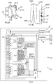
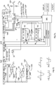
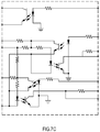
FIG. 7 illustrates an embodiment of the portable power supply according to the invention, whereFIG. 7A is a block diagram of the third embodiment,FIG. 7B is a schematic diagram of thePFC 1020,FIG. 7C is a schematic diagram of the optocoupling,FIG. 7D show four preferable output waves,FIG. 7E is a perspective view of the power supply, andFIG. 7F is a schematic diagram of the inverter output circuitry. -
FIG. 8 is a portable power supply/generator combination according to the invention. -
FIG. 9 is an alternate method for transporting the portable power supply - The present invention will now be described more fully hereinafter. This invention may, however, be embodied in many different forms and should not be construed as limited to the embodiments set forth herein; rather, these embodiments are provided so that this disclosure will be thorough and complete, and will fully convey the scope of the invention to those skilled in the art.
- In
FIGS. 1-2 , an example of a portable power supply is designated generally by thereference numeral 100. Thepower supply 100 preferably includes ahousing 101. Thehousing 101 may include ahandle 101H for carrying thepower supply 100. Thehousing 101 may have at least one and preferably twostraps 101S for carrying thepower supply 100. - A
cable 104 may be attached tohousing 101 for connecting to an AC plug. Thehousing 101 may have a cordwrap 101CW for wrapping thecable 104 therearound. -
Housing 101 may also haveoutlets 103 for connecting power tools and other electric apparatuses thereto. Preferably,housing 101 will carry two ormore outlets 103. - At least one
battery pack 102 can be disposed onhousing 101. Preferably four, five or sixbattery packs 102 are disposed onhousing 101. Persons skilled in the art will recognize that battery pack(s) 102 may be disposed inhousing 101 instead. - Persons skilled in the art will recognize that battery packs B1-Bn (and/or cells) may be connected in parallel as shown in
FIG. 2 , but could also be connected in series as discussed in other embodiments below. Thebattery packs 102 are preferably engageable with power tools. Eachbattery pack 102 preferably has the same components. Accordingly, the discussion as to battery pack B1 may apply to battery packs B2, B3, B4 ... Bn as well. - Referring to
FIGS. 1-2 , battery pack B1 has a housing BH, at least one cell BC disposed in housing BH. Cell(s) BC may have a lead acid, nickel cadmium, nickel metal hydride or lithium ion chemistries, or a combination thereof. Preferably cell(s) BC may have a lithium ion chemistry, such as lithium phosphate, lithium manganese, etc. For example, one possible chemistry could be the chemistry disclosed inUS Published Application No. 2005/0272214 . - Preferably, cells BC can output a total voltage of at least about 14 volts and preferably about 18-36 volts, and capable of providing a current of at least about 40 amps.
- A switching semiconductor BSR and a current sensor or resistor BR may be disposed between an output and cell(s) BC. A battery control BCC may receive information from the current sensor BR to control the switching semiconductor BSR.
- Battery control BCC may also receive other inputs from a controller 20 (and/or a microcontroller) or via other battery terminals. Battery control BCC can use such inputs (from
controller 20 or other outside components, such as resistors, capacitors, etc.) to access the correct pre-programmed settings for proper operation of switching semiconductor BSR. Persons skilled in the art are referred toUS Published Application Nos. 2005/0073282 and2005/0077878 , for further information on the components, operation and capabilities of battery pack B1. An alternate battery pack B1 may be found described inUS Application No. 60/949,740 - As shown in
FIG. 2 ,cable 104 is connected to apower supply circuit 25, which preferably provides power to controller 20.Power supply circuit 25 may convert the AC input received viacable 104 into DC power. -
Power supply 25 may also provide power to current sources i1, i2,...in. Persons skilled in the art will recognize that eachbattery pack 102 can have its own current source for charging. Alternatively, several battery packs 102 may be charged by one current source, or vice versa. -
Controller 20 preferably controls current sources for charging battery packs 102. Preferablycontroller 20 will receive voltage information of cells BC from each battery control BCC to turn on and/or off the current source feeding power (and/or reduce current) to theappropriate battery pack 102. Alternatively, battery controls BCC may instructcontroller 20 to turn on and/or off the current source feeding power (and/or reduce current) to theappropriate battery pack 102. This will prevent overcharging and/or undercharging ofbattery pack 102. -
Controller 20 also can enablebattery packs 102 to discharge, providing power toinverter 30. Because battery packs B1-Bn are in series, and each battery pack can have a voltage between about 14 volts to about 36 volts (for a total voltage of at least about 100 volts to at least about 216 volts DC), it is preferable thatinverter 30 be a high voltage power inverter. Persons skilled in the art will recognize that a boost circuit can be disposed between the battery packs 102 and theinverter 30 if a higher output voltage, e.g. 240 V, is desirable, less battery packs are used and/or it is not desirable to use a high voltage inverter. -
Inverter 30 then outputs about 120-240 volts in AC viaoutlets 103.Inverter 30 may be manually or automatically controlled so that the output frequency is between about 50 and about 60 Hz. Persons skilled in the art will recognize that it may be possible to output 240VAC viaoutlets 103 even if the AC input is 120VAC, or vice versa. Preferably, the power output will be about at least 3 kilowatts and preferably about 5-6 kilowatts peak. Persons skilled in the art will recognize this output may be obtained and/or supplemented by the electrical power provided by current sources i1, i2, ... in. Being thatpower supply 100 weighs about 13.6kg (30 pounds) to 22.7kg (50 pounds), the output power-to-weight ratio will be at least 133.3 watts/kg (60 watts/lb), and preferably between about 222.2 watts/kg (100 watts/lb) and about 444.4 watts/kg (200 watts/lb). - Accordingly, such arrangement allows the user to drive several power tools from
power supply 100, whetherpower supply 100 was connected to an AC source. If thepower supply 100 was connected to an AC source, battery packs 102 would be charged whenpower supply 100 was not supplying the peak power requirements. Furthermore, if the user needed to take this to a different room in the house, the user could disconnectpower supply 100 from the AC source and easily carry it to the room. - A second example of
power supply 100 is shown inFIGS. 3-5 , where like numerals refer to like parts. All the teachings of the previous example are hereby incorporated. - In this example, the controller or
microcontroller 20 preferably controls a single current source i0. However, persons skilled in the art will recognize that multiple current sources could be used instead, as in the previous embodiment. - Furthermore, instead of battery packs 102,
power supply 100 has discrete battery cells BC, preferably between 40-120 discrete battery cells. These are preferably paired up in parallel, with a transistor Q100 disposed across the cell terminals for a preferred capacity of about 288 to about 576 Watts/hour. Transistor Q100 is controlled by a cluster control CC0. - Basically, cluster control CCO monitors the voltage across battery cells BC. As the voltage becomes too high or reaches a target, cluster control CCO turns on transistor Q100 to shunt current through the transistor Q100, thus clamping the voltage across battery cells BC to prevent overcharging. At the same time, cluster control CCO creates an overvoltage signal that may cause the
controller 20 to lower the current being supplied by current source i0. - As seen in
FIG. 4 , cluster control CCO preferably monitors at least four pairs of battery cells BC. As before, cluster control CCO monitors the current across battery cells BC. If the voltage is too high (or the voltage reaches a predetermined target) for one pair of battery cells BC, cluster control CCO turns on the transistor Q100 associated in parallel to such pair of battery cells BC in order to shunt current through the transistor Q100, thus clamping the voltage across battery cells BC to prevent overcharging. Persons skilled in the art are referred to another voltage clamp structure discussed inUS Patent No. 4,719,401 . - Furthermore, cluster control CC0 creates an overvoltage signal ANYOVOUT that communicates to
controller 20 that at least one battery cell is being overcharged. Such signal may cause thecontroller 20 to lower the current being supplied by current source i0. - If cluster control CC0 detects that all four pairs of battery cells BC are being overcharged, have reached their target voltage or are fully charged, cluster control CC0 creates an overvoltage signal ALLOVOUT that communicates to
controller 20 that all associated battery cells BC have reached a predetermined target voltage. - Referring to
FIG. 4 , persons skilled in the art will recognize that several cluster controls CC0, CC1, ... CCn can be used to control charging of all the battery cells BC. While each cluster control may have a signal line for signal ANYOVOUT connected tocontroller 20, (or connected to an OR gate which output is fed into controller 20), it may be more efficient to provide each cluster control (e.g., CC1) with an input ANYOVIN, which receives the ANYOVOUT output of the cluster control above (e.g., CC0). The cluster control receiving the output from the previous cluster control may put such input into an OR gate with its own output, resulting into the ANYOVOUT output that will be sent to the cluster control below (e.g., CC2). In this manner,controller 20 only receives one input representative of the condition where one of the battery cells BC is being overcharged. - Similarly, while each cluster control may have a signal line for signal ALLOVOUT connected to
controller 20, (or connected to an AND gate which output is fed into controller 20), it may be more efficient to provide each cluster control (e.g., CC1) with an input ALLOVIN, which receives the ALLOVOUT output of the cluster control above (e.g., CC0). The cluster control receiving the output from the previous cluster control may put such input into an AND gate with its own output, resulting into the ALLOVOUT output that will be sent to the cluster control below (e.g., CC2). In this manner,controller 20 only receives one input representative of the conditions where all of the battery cells BC are being overcharged (or that all battery cells BC are fully charged). In such case,controller 20 can then turn off current source i0 and thus end charging. - As in the previous example, battery cells BC provide a DC power output to
inverter 30. Furthermore, as battery cells BC are discharging,controller 20 can enable current source i0 to supply power toinverter 30, in order to supplement the power input toinverter 30, as well as supply power tobattery cells 20 during discharge. - During discharge, cluster controls CC0, CC1, ... CCn preferably monitor the voltage of each pair of battery cells BC. If any cell is detected to reach a predetermined low voltage threshold, the cluster control generates an undervoltage signal ANYUVOUT. While each cluster control may have a signal line for signal ANYUVOUT connected to
controller 20, (or connected to an OR gate which output is fed into controller 20), it may be more efficient to provide each cluster control (e.g., CC1) with an input ANYUVIN, which receives the ANYUVOUT output of the cluster control above (e.g., CC0). The cluster control receiving the output from the previous cluster control may put such input into an OR gate with its own output, resulting into the ANYUVOUT output that will be sent to the cluster control below (e.g., CC2). In this manner,controller 20 only receives one input representative of the condition where one of the battery cells BC is under a threshold voltage. Upon receipt of such signal,controller 20 can turn on current source i0 to charge battery cells BC (ifpower supply 100 is connected to an AC source). Alternatively, signal ANYUVOUT can be used to turn off theinverter 30. - Preferably, cluster controls CC0, CC1, ... CCn are powered by battery cells BC. It is preferable to turn off cluster controls CC0, CC1, ... CCn when not needed so as to preserve battery run-time.
Controller 20 can send an ENABLE signal to each cluster control CC0, CC1, ... CCn. However, it may be more efficient to provide each cluster control (e.g., CC1) with an input ENIN, which receives the ENABLE signal fromcontroller 20. Such cluster control has an output ENOUT which can transmit the received ENABLE signal into the input ENIN of the cluster control above (e.g., CC0). In this manner,controller 20 only sends out one ENABLE signal across one wire, rather than across multiple wires.Microcontroller 20 can monitor ENOUT out of cluster control CCO to confirm that all cluster controls have become enabled. -
FIG. 5 is a circuit schematic for a part of a cluster control CC0. Persons skilled in the art will recognize that such circuitry is stackable depending upon how many pairs of battery cells BC are to be monitored. In other words, for the embodiment shown inFIG. 4 , the circuit schematic ofFIG. 5 would be repeated four times, one circuit per pair of battery cells BC. - The following table provides values for each component shown in
FIG. 5 :C100 C-0805 D100 D-BAS20 D101 D-BAS20 D102 D-BAS20 Q100 Q-TIP41 Q101 Q-BSS84 Q101 LMV431 Q102 Q-MMBT3906 Q103 Q-MMBT3906 Q104 Q-MMBT3906 Q105 Q-MMBT3906 Q106 Q-MMBT3904 Q107 Q-MMBT3904 Q108 Q-MMBTA92 Q109 Q- MMBTA92 R100 1 kiloohms R101 1 kiloohms R102 1 kiloohms R103 1 kiloohms R104 1 kiloohms R105 1 kiloohms R106 10 kiloohms R107 10 kiloohms R108 10 kiloohms R109 10 kiloohms R110 10 kiloohms R111 10 kiloohms R112 10 kiloohms R113 10 kiloohms R114 100 kiloohms R115 2.15 kiloohms, 1% R116 1.00 kiloohms, 1% R117 10 kiloohms R118 1 kiloohms R119 1 kiloohms R120 1 kiloohms R121 1 kiloohms U100 TL431 -
FIG. 6 is an alternative circuit schematic for a part of a cluster control CC0. Persons skilled in the art will recognize that such circuitry is stackable depending upon how many pairs of battery cells BC are to be monitored. In other words, for the embodiment shown inFIG. 4 , the circuit schematic ofFIG. 6 would be repeated four times, one circuit per pair of battery cells BC. - The following table provides values for each component shown in
FIG. 6 :D100' BAS16 F100' ¼ Amp F101' ¼ Amp F102' ¼ Amp Q100' D44H8 Q101' MMBT3906 Q102' MMBT3904 Q103' MMBT 3906 Q104' MMBT3906 Q105' MMBT3906 Q106' NTR2101 Q107' MMBT3906 Q108' MMBT3904 Q109' MMBT3906 Q110' MMBT3904 Q111' MMBT3904 Q112' MMBT3904 Q113' MMBT3904 R100' 10 kiloohms R101' 1 kiloohm R102' 100 kiloohms R103' 10 kiloohms R104' 1 kiloohm R105' 1.00 kiloohm R106' 10 kiloohms R107' 10 kiloohms R108' 1 kiloohm R109' 1 kiloohm R110' 1 kiloohm R111' 10 kiloohms R112' 100 kiloohms R113' 100 kiloohms R114' 2.15 kiloohms R115' 10 kiloohms R116' 10 kiloohms R117' 10 kiloohms R118' 10 kiloohms R119' 100 kiloohms R120' 100 kiloohms R121' 100 kiloohms U100' TL431CPK - Persons skilled in the art will recognize that using cluster controls rather than one single control for all battery cells will allow the use of cheaper lower voltage electronics, whereas a single control may require the use of more expensive high voltage electronics that can handle the entire voltage range of the battery cells BC. Furthermore, persons skilled in the art will recognize that cluster control CCO may be integrated into an application specific integrated circuit (ASIC).
- An embodiment of the power supply is shown in
FIG. 7 , where like numerals refer to like parts. Referring toFIG. 7A , thepower supply 100 preferably has aline filter 1000, arectifier 1010 and a power factor/boost converter (PFC) 1020. ThePFC 1020 is preferably a controllable buck converter to boost power as necessary. A schematic diagram ofPFC 1020 is shown inFIG. 7B . The following table provides values for each component shown inFIG. 7B :C200 100 nanofarads C201 1 microfarads C202 10 nanofarads C203 10 nanofarads C204 470 nanofarads C205 2.2 nanofarads C206 10 microfarads/50 volts C207 100 nanofarads C208 220 picofarads C209 100 picofarads C210 330 picofarads D200 LL4148 D201 LL4148 D202 LL4148 L200 500 microhenries Q200 BC8570 Q201 STP12NM50FP Q202 STP12NM50FP R200 6.6 megaohm R201 880 kiloohms R202 680 kiloohms R203 680 kiloohms R204 15 kiloohms R205 100 kiloohms R206 56 kiloohms R207 5.1 kiloohms R208 30 kiloohms R209 820 kiloohms R210 820 kiloohms R211 10 kiloohms R212 150 kiloohms R213 240 kiloohms R214 1.0 kiloohms R215 47 kiloohms R216 1.5 kiloohms R217 15 kiloohms R218 3.3 kiloohms R219 6.8 ohms R220 6.8 ohms R221 1.0 kiloohms R222 0.39 ohms R223 0.39 ohms R224 0.39 ohms R225 0.39 ohms U200 L6563 - The output of the
PFC 1020 goes into an isolated DC-DC converter 1030 that can provide constant current output. The output of theconverter 1030 can charge battery packs B1, ... Bn, and/or provide power to aninverter 1040. -
Inverter 1040 is preferably a non-isolated full-bridge DC-AC inverter. Theinverter 1040 preferably can run at least one of four output waves: a pure sinewave (shown inFIG. 7D(a) ), an AC pulse (shown inFIG. 7D(b) ), a modified AC pulse (shown inFIG. 7D(c) ) and a modified sinewave (shown inFIG. 7D(d) ). - Persons skilled in the art will recognize that the modified sinewave of
FIG. 7D(d) may provide more power than the pure sinewave having the same amplitude, while still providing a recognizable zero crossing. This modified sinewave over time preferably has a first positive voltage step level, a second higher positive voltage step level, a third lower positive voltage step level (which could be at the same level as the first voltage step level), a fourth negative voltage step level (with very little time between the transition from the third and fourth voltage step levels and/or at 0V), a fifth higher negative voltage step level, and a sixth lower negative voltage step level (which could be at the same level as the fourth voltage step level). The pattern is then repeated with very little time between the transition from the sixth and first voltage step levels and/or at 0V. Persons skilled in the art will recognize that, following this pattern, the amount of time spent at 0V is very small or negligible, e.g., less than 10-25 microseconds. (Persons skilled in the art will recognize that other power supplies, such as generators, can be design to output such waveform.) Persons skilled in the art will recognize that, at each step level, the voltage will preferably be substantially constant. -
FIG. 7F shows a schematic ofinverter 1040 that can be used to obtain different output waveforms which may or may not include all of the waveforms shown inFIG. 7D .Inverter 1040 may include an isolated step-down DC/DC converter with a voltage controlledoutput 1042. - Preferably
inverter 1040 has acontroller 1041 which receives inputs from theinverter controller 1050 and/or the battery management unit BMU.Controller 1041 then switches the different transistors that are connected to the DC input and/or to the output ofconverter 1042 as shown inFIG. 7F .Controller 1041 would preferably switch the transistors in a specific order to create the desired output wave. - Persons skilled in the art will recognize that the transistors shown in
FIG. 7F are preferably insulated-gate bipolar transistors (IGBTs). - As shown in
FIG. 7A , some circuitry is disposed betweeninverter 1040 and outlet(s) 103. This circuitry can help in shaping the output sinewave, provide current output information toinverter controller 1050 and/or battery management unit BMU, and/or stop current flow via a standard and/or thermal circuit breaker(s) CB. -
Inverter 1040 is preferably controlled by theinverter controller 1050.Inverter controller 1050 receives inputs from output on/offswitch 1051 and wave selection switch 1052. According to these inputs,inverter controller 1050 would activate several lines for switching bridge switches insideinverter 1040 to provide the desired wave output. - The
inverter controller 1050 is also in communication with the battery management unit BMU, providing information as to whether the inverter is on or off, if a load is connected to the inverter, etc. Based on this information, as well as the state of charge of the batteries, the battery management unit BMU can turn off the DC-DC converter 1030, request a low current output, or request a high current output. For example, if the battery packs can handle the entire inverter current draw, the battery management unit BMU may turn off the DC-DC converter 1030. On the other hand, if the batteries are not charged enough, but the load connected toinverter 1040 is not too large, the battery management unit BMU may request a high current output. The DC-DC converter 1030 may in turn send a low load signal to thePFC 1020 so that thePFC 1020 does not boost its output or is turned off. - The DC-
DC converter 1030 may also provide the high current output to charge battery packs B1-Bn. The DC-DC converter 1030 may also provide a low current output to balance battery packs B1-Bn. These current output settings would be selected by the battery management unit BMU. - If the
PFC 1020 malfunctions, it can send a malfunction signal to DC-DC converter 1030, preferably shutting down DC-DC converter 1030. - Referring to
FIG. 7A , battery packs B1-Bn are preferably connected in series. The battery packs B1-Bn preferably have cells BC, electronics BCC, a power transistor or triac BQ disposed in series with cells BC, and a diode BD disposed across triac BQ. - Preferably, the quantity and voltages of these battery packs are selected so that the combined voltage will be more than 170VDC, to meet the peak voltage of 120V single phase AC. In particular, six 36V battery packs may be provided.
- Each battery pack is preferably connected to the battery management unit BMU via an optocoupling isolator OC. A schematic diagram of such optocoupling isolator OC is shown in
FIG. 7C . Persons skilled in the art will recognize that providing such optocoupling isolator OC will allow battery management unit BMU to handle the different varying voltages in battery packs B1-Bn. - Typically, the battery management unit BMU is normally disconnected from battery packs B1-Bn and connected only after the start switch SSW is pressed. When start switch SSW is pressed, power supply PS provides a signal to battery management unit BMU, after which the battery management unit BMU sends a signal to switch SPB, closing such switch SPB so that battery management unit BMU receives power from another power supply PS.
- Persons skilled in the art will recognize that, if
power supply 100 is connected to an AC source, battery management unit BMU will always be powered on without requiring any input at start switch SSW. - Battery management unit BMU may have a display connected thereto to provide information to the user, such as how much power remains in
power supply 100. Other information that could be displayed include but are not limited to battery diagnostics,power supply 100 diagnostics, etc. - Battery management unit BMU may have an input/output port. This input/outport port can be used to connect the battery management unit BMU to a computer or reader apparatus. With such connection, information collected or stored in the battery management unit BMU can be downloaded to and/or accessed by the computer or reader apparatus for later and/or real-time analysis of the functioning of
power supply 100. Persons skilled in the art will recognize that such connection may also allow programming or reprogramming of the software controlling the battery management unit BMU and/or the battery packs B1-Bn. Persons skilled in the art will recognize that the input/output port may be an infrared port, a USB port, a serial port, optoelectronics port, a parallel port, and/or an RF (radio frequency) communicator. - Battery management unit BMU may receive inputs from locking modules, such as a keylock, a key fob, fingerprint reader, key pad, etc., that maintains the
power supply 100 in a locked unusable status until the proper input is provided. - A
heat source 1060, is provided adjacent to battery packs B1-Bn to warm up the battery packs B1-Bn. Such warming up operation allows the battery packs to be used in a low temperature, e.g., below zero degrees Celsius. The battery packs B1-Bn are warmed by the exhaust of a gas engine, of a gas-engine generator 500 (as shown inFIG. 7E ). Ahose 510 ducts the exhaust gases fromgenerator 500 topower supply 100. - Because of the high energy density of the
power supply 100, it is possible to combinepower supply 100 with alow weight generator 500 and still provide an output usable in a jobsite, as shown inFIG. 8 . This is becausegenerator 500 does not need to output enough power for the jobsite-just enough to charge battery packs B1-Bn. - For example,
power supply 100 may weigh about 13.6kgs (30 pounds) to 22.7kgs (50 pounds), and preferably weighs about 15.9kgs (35 pounds).Such power supply 100 may output about 6000 watts max and about 700 watts constant. Ifsuch power supply 100 were combined with a Honda EU1000i generator (a 1000 watt generator), the combined weight will be about 29kgs (64 pounds) dry weight (or 30.6kgs (67.5 pounds) with 1.9 litres (0.5 gallon) of gas, i.e., wet weight), making this combination very manageable to carry around in a jobsite. Such combination will output about 208.4 watts per kg (93.8 watts per pound) (dry weight) and 197.8 watts per kg (89 watts per pound) (wet weight). By contrast, the Honda EB5000i (a 5000 watt max generator) would weigh about 89.8kgs (198 pounds) (thus outputting about 56.2kgs (25.3 watts per pound)). Similarly, the Honda EB7000i (a 6500 watt max generator) would weight about 89.8kgs (198 pounds) (thus outputting about 72.9 watts per kg (32.8 watts per pound)). - Persons skilled in the art will recognize that it is preferable that the generator and
power supply 100 combination will preferably output at least 5000-6000 watts at at least 106.7 watts per kg (48 watts per pound) and preferably at least 135.3 watts per kg (60 watts per pound). - Because of the low power required to charge battery packs B1-Bn, users can select less expensive power sources to charge
power supply 100. For example, users can use a smaller, less expensive generator that, for example, uses a Stirling engine or fuel cells, than a larger generator using the same technology, e.g., a Stirling engine or fuel cells which outputs 6 kilowatts. Because the larger more expensive generator is no longer needed, the price-to-watts ratio is substantially lowered. - Referring to
FIG. 7E , thegenerator 500 has at least oneprotrusion 501 for receiving thepower supply 100. Protrusion(s) 501 would engage a feature inhousing 101 so thatpower supply 100 cannot be moved horizontally relative togenerator 500, only lifted therefrom. - Persons skilled in the art will recognize that it is preferable that similar protrusion(s) or features are disposed on the top of
power supply 100, allowingmultiple power supplies 100 to be stacked. -
Generator 500 may also havelatches 502 for fixedly attachingpower supply 100 togenerator 500.Latches 502 may engage afeature 101L onroll cage 101R and/orhousing 101, so that thepower supply 100 cannot be lifted offgenerator 500. Persons skilled in the art will recognize that latches 502 may also be used to attach lamps and/or other accessories togenerator 500. - Persons skilled in the art will recognize that latches 502 may be disposed on
housing 101 and/orroll cage 101R to engage afeature 101L ongenerator 500. In such case, latches 502 may also be used to attach lamps and/or other accessories topower supply 100. -
FIG. 9 illustrates another method for transportingpower supply 100 andgenerator 500.Power supply 100 and/orgenerator 500 may be attached to adolly 600.Power supply 100 may have hooks 101HH onhousing 101, allowingpower supply 100 to be hooked onto a beam (not shown) ofdolly 600. Persons skilled in the art will recognize that hooks 101HH are preferably rotatable so they may be rotated to be flat againsthousing 101 when not in use. Springs (not shown) attached to hooks 101HH may be provided to bias hooks 101HH towardshousing 101. - Referring to
FIGS. 7A and7E , it may be preferable to providepower supply 100 with a 12V DC output. Persons skilled in the art will recognize that this could be done by providing an alternate power path with a step-down transformer and rectifier, or a separate12V DC converter 1070 could be provided after the rectified output, as shown inFIG. 7A . Persons skilled in the art will recognize that the12V DC converter 1070 may derive power from the battery packs B1-Bn. - As shown in
FIG. 7A , a relay or a semiconductor switch R may be used to switch between powering the 12V DC converter from AC power (whenpower supply 100 is plugged into an AC source) or battery packs B1-Bn. The output of theDC converter 1070 can be provided to a cigarette lighter-type outlet 1071. - A switch or semiconductor switch DS may be disposed between switch R and the battery packs B1-Bn. Such switch DS is preferably controlled by battery management unit BMU. If battery management unit BMU detects that battery packs B1-Bn are not charged enough to power
DC converter 1070, it may open switch DS to prevent the overdischarge of battery packs B1-Bn. - Persons skilled in the art should also recognize that other converters may be used to obtain different voltages. For example, an
alternate converter 1070 may provide an output about 5 volts. Preferably, the output of theDC converter 1070 can be provided to an USB outlet. - It may also be preferable to provide
power supply 100 with an audio and/orvisual circuit 1080, which can provide audio output through speaker(s) 1081 and/or video output throughdisplay 1082. Such audio and/orvisual circuit 1080 may include a radio, a CD player, an MP3 player, and/or a DVD player. Preferably, audio and/orvisual circuit 1080 may include an auxiliary input to plug in other sources of audio and/or video input, such as an iPod®, a hand-held DVD player, a video game, etc. As before, audio and/orvisual circuit 1080 may be powered from the AC mains line, the output ofrectifier 1010 and/or the battery packs B1-Bn. The power source may be selected manually by the user, or automatically via circuitry, such as switch R, etc. As before, a switch DS may be disposed between switch R and the battery packs B1-Bn and controlled by battery management unit BMU to prevent overdischarge of battery packs B1-Bn. - It may also be preferable to provide
power supply 100 with acharger 1090 for charging power tool battery packs 1091. As before,charger 1090 may be powered from the AC mains line, the output ofrectifier 1010 and/or the battery packs B1-Bn. The power source may be selected manually by the user, or automatically via circuitry, such as switch R, etc. As before, a switch DS may be disposed between switch R and the battery packs B1-Bn and controlled by battery management unit BMU to prevent overdischarge of battery packs B1-Bn. - It may also be preferable to provide
power supply 100 with alamp 1095, as shown inFIGS. 7A and7E . As before,lamp 1095 may be powered from the AC mains line, the output ofrectifier 1010 and/or the battery packs B1-Bn. The power source may be selected manually by the user, or automatically via circuitry, such as switch R, etc. As before, a switch DS may be disposed between switch R and the battery packs B1-Bn and controlled by battery management unit BMU to prevent overdischarge of battery packs B1-Bn. -
Lamp 1095 preferably includes alight assembly 1095L movably connected tohousing 101 viaarms 1095A.Light assembly 1095L preferably comprises a light housing 1095LH, which may support supports a reflector 1095LR and a lamp bulb 1095LL. Lamp bulb 1095LL may be a light bulb, a halogen bulb, a fluorescent tube, light emitting diodes, etc. Preferably lamp bulb 1095LL is a double-D shaped fluorescent tube, rated at about 38 watts. Persons skilled in the art are referred toUS Application No. 11/559,002, filed November 13, 2006 -
Housing 101 may havebars 101R forming a roll cage disposed there housing 101 to protecthousing 101.Bars 101R may be made of plastic or metal, and may be flexibly connected tohousing 101, as is shown inUS Patent No. 6,427,070 . -
Housing 101 may also havelegs 101F. Preferablylegs 101F are rotatably attached tohousing 101 so they may be moved between a collapsed storage position to an extended use position. Persons skilled in the art will recognize that it is preferable to designlegs 101F of a certain length so thathousing 101 can be disposed above mud and/or standing water ifpower supply 100 is disposed on a construction jobsite ground. - Referring to
FIGS. 1 and3 , it is preferable that the center of gravity CG ofpower supply 100 is disposed substantially underneathhandle 101H. This provides for a unit that is well-balanced during transportation. Preferably, center of gravity CG will be disposed in a plane 101P that includes the centerline ofhandle 101H. Plane 101P is preferably located in a substantially vertical orientation that is generally parallel to a vertical (longitudinal) axis USRA of a user USR. - It is preferable that the plane 101P be selected so that it is relatively close to
rear wall 101W. The user USR may then be able to transportpower supply 100 such that therear wall 101W is proximate to a lateral side USRS of the user USR (i.e., within about 10 inches of the lateral side USRS, and preferably about 3 inches to about 7 inches), and the user's wrist USRW is not in a state of flexion. - With such arrangement, the user USR may be able to comfortably carry the
power supply 100, as well as to easily pivot thepower supply 100 between the substantially vertical transport position and a position where thehousing 101 is disposed on rear wall101W. Power supply 100 may be used in this orientation, ensuring stability during operation or transport, and minimizing jostling or tipping over of the unit.
Claims (3)
- A system comprising a portable power supply and a gas-engine generator, the portable power supply comprising:a housing;at least one battery cell (BC) disposed in the housing;an inverter (1040) connected to the at least one battery cell (BC); anda heat source adjacent to the at least one battery cell (BC) for warming the at least one battery cell (BC), wherein the heat source is an exhaust of the gas engine generator;wherein there is further provided a hose (510) to duct the exhaust gases from the gas-engine generator (500) to the power supply; andwherein the gas-engine generator further comprises at least one protrusion (501) for receiving the power supply and for engaging a feature in the housing (101) so that the power supply can not be moved horizontally relative to the gas-engine generator.
- A system comprising a portable power supply and gas-engine generator as claimed in Claim 1 wherein the gas-engine generator comprises latches for fixed attaching the power supply to the gas-engine generator.
- A system comprising a portable power supply and gas-engine generator as claimed in claim 2 whrein the latches engage a feature (101L) on a roll cage (101R) of the gas-engine generator and / or the housing (101) of portable power supply so that the power supply (100) cannot be lifted off the gas-engine generator.
Priority Applications (1)
| Application Number | Priority Date | Filing Date | Title |
|---|---|---|---|
| EP14193515.5A EP2866327B1 (en) | 2007-02-26 | 2008-02-26 | Portable power supply |
Applications Claiming Priority (3)
| Application Number | Priority Date | Filing Date | Title |
|---|---|---|---|
| US89154007P | 2007-02-26 | 2007-02-26 | |
| PCT/US2008/055014 WO2008106447A2 (en) | 2007-02-26 | 2008-02-26 | Portable power supply |
| US12/037,298 US20080265678A1 (en) | 2007-02-26 | 2008-02-26 | Portable Power Supply |
Related Child Applications (2)
| Application Number | Title | Priority Date | Filing Date |
|---|---|---|---|
| EP14193515.5A Division EP2866327B1 (en) | 2007-02-26 | 2008-02-26 | Portable power supply |
| EP14193515.5A Division-Into EP2866327B1 (en) | 2007-02-26 | 2008-02-26 | Portable power supply |
Publications (3)
| Publication Number | Publication Date |
|---|---|
| EP2122803A2 EP2122803A2 (en) | 2009-11-25 |
| EP2122803A4 EP2122803A4 (en) | 2013-07-17 |
| EP2122803B1 true EP2122803B1 (en) | 2018-07-18 |
Family
ID=39721824
Family Applications (1)
| Application Number | Title | Priority Date | Filing Date |
|---|---|---|---|
| EP08730754.2A Not-in-force EP2122803B1 (en) | 2007-02-26 | 2008-02-26 | Portable power supply |
Country Status (3)
| Country | Link |
|---|---|
| US (1) | US20080265678A1 (en) |
| EP (1) | EP2122803B1 (en) |
| WO (1) | WO2008106447A2 (en) |
Families Citing this family (13)
| Publication number | Priority date | Publication date | Assignee | Title |
|---|---|---|---|---|
| US9007023B2 (en) * | 2012-03-14 | 2015-04-14 | Elite Power Solutions Llc | Portable power supply |
| US8960708B2 (en) | 2012-11-30 | 2015-02-24 | Kohler Co. | Enclosure guide system for a towable generator |
| GB2518840B (en) * | 2013-10-01 | 2015-08-19 | Sharlein Smales | A battery powered AC power source |
| US10044197B2 (en) | 2013-12-12 | 2018-08-07 | Milwaukee Electric Tool Corporation | Portable power supply and battery charger |
| US10749430B2 (en) | 2015-03-13 | 2020-08-18 | Positec Power Tools (Suzhou) Co., Ltd. | Power transmission apparatus and control method therefor, and power supply system |
| US20170302095A1 (en) * | 2016-04-18 | 2017-10-19 | Vitec Videocom Inc. | Smart charger with selective discharge capability |
| JP2018064373A (en) * | 2016-10-13 | 2018-04-19 | 東京電力ホールディングス株式会社 | Portable power supply device |
| CN207304039U (en) * | 2017-07-07 | 2018-05-01 | 深圳市正浩创新科技有限公司 | Mobile power |
| USD1009790S1 (en) | 2020-03-19 | 2024-01-02 | Milwaukee Electric Tool Corporation | Single battery pack inverter |
| WO2021188922A1 (en) * | 2020-03-19 | 2021-09-23 | Milwaukee Electric Tool Corporation | Single battery pack inverter |
| US12294232B2 (en) | 2020-12-18 | 2025-05-06 | Milwaukee Electric Tool Corporation | Portable power supply |
| WO2022191233A1 (en) * | 2021-03-10 | 2022-09-15 | 本田技研工業株式会社 | Electric power device, and control method for same |
| CN113054732B (en) * | 2021-03-25 | 2024-06-07 | 深圳市双向诚科技有限公司 | Automatic switching power supply equipment for electric fire-fighting illuminating lamp |
Family Cites Families (11)
| Publication number | Priority date | Publication date | Assignee | Title |
|---|---|---|---|---|
| US3581212A (en) * | 1969-07-31 | 1971-05-25 | Gen Electric | Fast response stepped-wave switching power converter circuit |
| DE7824114U1 (en) * | 1978-08-12 | 1979-10-18 | Diehl Gmbh & Co, 8500 Nuernberg | PORTABLE, RECHARGEABLE DEVICE |
| DE3643558A1 (en) | 1986-12-19 | 1988-07-07 | Wolf Geraete Gmbh | ELECTRIC MOTOR DRIVE SYSTEM |
| US4748344A (en) * | 1987-03-23 | 1988-05-31 | Peter Sing | Portable power supply carrier |
| US4920475A (en) * | 1988-03-07 | 1990-04-24 | California Institute Of Technology | Integrated traction inverter and battery charger apparatus |
| US5138544A (en) * | 1991-04-02 | 1992-08-11 | Westinghouse Electric Corp. | Harmonically modified twelve-pole inverter |
| JP3044975B2 (en) * | 1992-12-10 | 2000-05-22 | トヨタ自動車株式会社 | Battery heating device for electric vehicles |
| US5495403A (en) * | 1994-12-24 | 1996-02-27 | Sundstrand Corporation | Stepped-waveform power converter utilizing a summing transformer and a single inverter bridge |
| US5784267A (en) * | 1996-10-17 | 1998-07-21 | Onan Corporation | Quasi-sine wave and stepped square wave AC to AC converter |
| US20020114983A1 (en) * | 2001-02-21 | 2002-08-22 | Coleman Powermate, Inc. | Portable fuel cell electric power source |
| US6753651B1 (en) * | 2002-05-01 | 2004-06-22 | The Bodine Company, Inc. | Emergency ballast with battery heater |
-
2008
- 2008-02-26 US US12/037,298 patent/US20080265678A1/en not_active Abandoned
- 2008-02-26 WO PCT/US2008/055014 patent/WO2008106447A2/en not_active Ceased
- 2008-02-26 EP EP08730754.2A patent/EP2122803B1/en not_active Not-in-force
Non-Patent Citations (1)
| Title |
|---|
| None * |
Also Published As
| Publication number | Publication date |
|---|---|
| EP2122803A4 (en) | 2013-07-17 |
| EP2122803A2 (en) | 2009-11-25 |
| WO2008106447A3 (en) | 2008-11-27 |
| US20080265678A1 (en) | 2008-10-30 |
| WO2008106447A2 (en) | 2008-09-04 |
Similar Documents
| Publication | Publication Date | Title |
|---|---|---|
| EP2866327B1 (en) | Portable power supply | |
| US20080265678A1 (en) | Portable Power Supply | |
| US11296528B2 (en) | Adaptor and power station | |
| US9991706B2 (en) | Portable alternating current inverter having reduced imipedance losses | |
| US11251623B2 (en) | Portable power supply | |
| KR101197243B1 (en) | Portable Power Supply Device | |
| US11646596B2 (en) | Portable power station having multiple battery modules and method of operating a portable power station having multiple battery modules | |
| US9739429B2 (en) | Light apparatus | |
| CN115663817A (en) | Electric energy transmission device, control method thereof and power supply system | |
| US10302259B2 (en) | Low voltage lighting system for use during power outages | |
| CN101416366A (en) | Battery powered welder system utilizing vehicle powered AC inverter | |
| CN220368486U (en) | Charging device | |
| US7989980B2 (en) | Portable self regenerating power system | |
| CN117118001A (en) | A high-life charge and discharge system and energy storage device | |
| JP2003273976A (en) | Method for charging battery built in mobile phone and charger for the mobile phone | |
| US20250178113A1 (en) | Hybrid chargers and portable hybrid welding-type systems | |
| CN117526493A (en) | Power equipment and power supply units | |
| JPH05122858A (en) | Power storage battery charger |
Legal Events
| Date | Code | Title | Description |
|---|---|---|---|
| PUAI | Public reference made under article 153(3) epc to a published international application that has entered the european phase |
Free format text: ORIGINAL CODE: 0009012 |
|
| 17P | Request for examination filed |
Effective date: 20090923 |
|
| AK | Designated contracting states |
Kind code of ref document: A2 Designated state(s): AT BE BG CH CY CZ DE DK EE ES FI FR GB GR HR HU IE IS IT LI LT LU LV MC MT NL NO PL PT RO SE SI SK TR |
|
| DAX | Request for extension of the european patent (deleted) | ||
| A4 | Supplementary search report drawn up and despatched |
Effective date: 20130618 |
|
| RIC1 | Information provided on ipc code assigned before grant |
Ipc: H02J 7/00 20060101ALI20130612BHEP Ipc: H02M 7/00 20060101ALI20130612BHEP Ipc: H02J 9/00 20060101AFI20130612BHEP Ipc: H02M 7/49 20070101ALI20130612BHEP |
|
| 17Q | First examination report despatched |
Effective date: 20150626 |
|
| GRAP | Despatch of communication of intention to grant a patent |
Free format text: ORIGINAL CODE: EPIDOSNIGR1 |
|
| STAA | Information on the status of an ep patent application or granted ep patent |
Free format text: STATUS: GRANT OF PATENT IS INTENDED |
|
| INTG | Intention to grant announced |
Effective date: 20180223 |
|
| GRAS | Grant fee paid |
Free format text: ORIGINAL CODE: EPIDOSNIGR3 |
|
| GRAA | (expected) grant |
Free format text: ORIGINAL CODE: 0009210 |
|
| STAA | Information on the status of an ep patent application or granted ep patent |
Free format text: STATUS: THE PATENT HAS BEEN GRANTED |
|
| AK | Designated contracting states |
Kind code of ref document: B1 Designated state(s): AT BE BG CH CY CZ DE DK EE ES FI FR GB GR HR HU IE IS IT LI LT LU LV MC MT NL NO PL PT RO SE SI SK TR |
|
| REG | Reference to a national code |
Ref country code: GB Ref legal event code: FG4D |
|
| REG | Reference to a national code |
Ref country code: CH Ref legal event code: EP |
|
| REG | Reference to a national code |
Ref country code: IE Ref legal event code: FG4D |
|
| REG | Reference to a national code |
Ref country code: DE Ref legal event code: R096 Ref document number: 602008056058 Country of ref document: DE |
|
| REG | Reference to a national code |
Ref country code: AT Ref legal event code: REF Ref document number: 1020403 Country of ref document: AT Kind code of ref document: T Effective date: 20180815 |
|
| REG | Reference to a national code |
Ref country code: NL Ref legal event code: MP Effective date: 20180718 |
|
| REG | Reference to a national code |
Ref country code: LT Ref legal event code: MG4D |
|
| REG | Reference to a national code |
Ref country code: AT Ref legal event code: MK05 Ref document number: 1020403 Country of ref document: AT Kind code of ref document: T Effective date: 20180718 |
|
| PG25 | Lapsed in a contracting state [announced via postgrant information from national office to epo] |
Ref country code: NL Free format text: LAPSE BECAUSE OF FAILURE TO SUBMIT A TRANSLATION OF THE DESCRIPTION OR TO PAY THE FEE WITHIN THE PRESCRIBED TIME-LIMIT Effective date: 20180718 |
|
| PG25 | Lapsed in a contracting state [announced via postgrant information from national office to epo] |
Ref country code: SE Free format text: LAPSE BECAUSE OF FAILURE TO SUBMIT A TRANSLATION OF THE DESCRIPTION OR TO PAY THE FEE WITHIN THE PRESCRIBED TIME-LIMIT Effective date: 20180718 Ref country code: AT Free format text: LAPSE BECAUSE OF FAILURE TO SUBMIT A TRANSLATION OF THE DESCRIPTION OR TO PAY THE FEE WITHIN THE PRESCRIBED TIME-LIMIT Effective date: 20180718 Ref country code: NO Free format text: LAPSE BECAUSE OF FAILURE TO SUBMIT A TRANSLATION OF THE DESCRIPTION OR TO PAY THE FEE WITHIN THE PRESCRIBED TIME-LIMIT Effective date: 20181018 Ref country code: BG Free format text: LAPSE BECAUSE OF FAILURE TO SUBMIT A TRANSLATION OF THE DESCRIPTION OR TO PAY THE FEE WITHIN THE PRESCRIBED TIME-LIMIT Effective date: 20181018 Ref country code: IS Free format text: LAPSE BECAUSE OF FAILURE TO SUBMIT A TRANSLATION OF THE DESCRIPTION OR TO PAY THE FEE WITHIN THE PRESCRIBED TIME-LIMIT Effective date: 20181118 Ref country code: FI Free format text: LAPSE BECAUSE OF FAILURE TO SUBMIT A TRANSLATION OF THE DESCRIPTION OR TO PAY THE FEE WITHIN THE PRESCRIBED TIME-LIMIT Effective date: 20180718 Ref country code: GR Free format text: LAPSE BECAUSE OF FAILURE TO SUBMIT A TRANSLATION OF THE DESCRIPTION OR TO PAY THE FEE WITHIN THE PRESCRIBED TIME-LIMIT Effective date: 20181019 Ref country code: PL Free format text: LAPSE BECAUSE OF FAILURE TO SUBMIT A TRANSLATION OF THE DESCRIPTION OR TO PAY THE FEE WITHIN THE PRESCRIBED TIME-LIMIT Effective date: 20180718 Ref country code: LT Free format text: LAPSE BECAUSE OF FAILURE TO SUBMIT A TRANSLATION OF THE DESCRIPTION OR TO PAY THE FEE WITHIN THE PRESCRIBED TIME-LIMIT Effective date: 20180718 |
|
| PG25 | Lapsed in a contracting state [announced via postgrant information from national office to epo] |
Ref country code: LV Free format text: LAPSE BECAUSE OF FAILURE TO SUBMIT A TRANSLATION OF THE DESCRIPTION OR TO PAY THE FEE WITHIN THE PRESCRIBED TIME-LIMIT Effective date: 20180718 Ref country code: ES Free format text: LAPSE BECAUSE OF FAILURE TO SUBMIT A TRANSLATION OF THE DESCRIPTION OR TO PAY THE FEE WITHIN THE PRESCRIBED TIME-LIMIT Effective date: 20180718 Ref country code: HR Free format text: LAPSE BECAUSE OF FAILURE TO SUBMIT A TRANSLATION OF THE DESCRIPTION OR TO PAY THE FEE WITHIN THE PRESCRIBED TIME-LIMIT Effective date: 20180718 |
|
| REG | Reference to a national code |
Ref country code: DE Ref legal event code: R097 Ref document number: 602008056058 Country of ref document: DE |
|
| PG25 | Lapsed in a contracting state [announced via postgrant information from national office to epo] |
Ref country code: RO Free format text: LAPSE BECAUSE OF FAILURE TO SUBMIT A TRANSLATION OF THE DESCRIPTION OR TO PAY THE FEE WITHIN THE PRESCRIBED TIME-LIMIT Effective date: 20180718 Ref country code: CZ Free format text: LAPSE BECAUSE OF FAILURE TO SUBMIT A TRANSLATION OF THE DESCRIPTION OR TO PAY THE FEE WITHIN THE PRESCRIBED TIME-LIMIT Effective date: 20180718 Ref country code: EE Free format text: LAPSE BECAUSE OF FAILURE TO SUBMIT A TRANSLATION OF THE DESCRIPTION OR TO PAY THE FEE WITHIN THE PRESCRIBED TIME-LIMIT Effective date: 20180718 Ref country code: IT Free format text: LAPSE BECAUSE OF FAILURE TO SUBMIT A TRANSLATION OF THE DESCRIPTION OR TO PAY THE FEE WITHIN THE PRESCRIBED TIME-LIMIT Effective date: 20180718 |
|
| PLBE | No opposition filed within time limit |
Free format text: ORIGINAL CODE: 0009261 |
|
| STAA | Information on the status of an ep patent application or granted ep patent |
Free format text: STATUS: NO OPPOSITION FILED WITHIN TIME LIMIT |
|
| PG25 | Lapsed in a contracting state [announced via postgrant information from national office to epo] |
Ref country code: SK Free format text: LAPSE BECAUSE OF FAILURE TO SUBMIT A TRANSLATION OF THE DESCRIPTION OR TO PAY THE FEE WITHIN THE PRESCRIBED TIME-LIMIT Effective date: 20180718 Ref country code: DK Free format text: LAPSE BECAUSE OF FAILURE TO SUBMIT A TRANSLATION OF THE DESCRIPTION OR TO PAY THE FEE WITHIN THE PRESCRIBED TIME-LIMIT Effective date: 20180718 |
|
| 26N | No opposition filed |
Effective date: 20190423 |
|
| PG25 | Lapsed in a contracting state [announced via postgrant information from national office to epo] |
Ref country code: SI Free format text: LAPSE BECAUSE OF FAILURE TO SUBMIT A TRANSLATION OF THE DESCRIPTION OR TO PAY THE FEE WITHIN THE PRESCRIBED TIME-LIMIT Effective date: 20180718 |
|
| REG | Reference to a national code |
Ref country code: CH Ref legal event code: PL |
|
| PG25 | Lapsed in a contracting state [announced via postgrant information from national office to epo] |
Ref country code: LU Free format text: LAPSE BECAUSE OF NON-PAYMENT OF DUE FEES Effective date: 20190226 Ref country code: MC Free format text: LAPSE BECAUSE OF FAILURE TO SUBMIT A TRANSLATION OF THE DESCRIPTION OR TO PAY THE FEE WITHIN THE PRESCRIBED TIME-LIMIT Effective date: 20180718 |
|
| REG | Reference to a national code |
Ref country code: BE Ref legal event code: MM Effective date: 20190228 |
|
| REG | Reference to a national code |
Ref country code: IE Ref legal event code: MM4A |
|
| PG25 | Lapsed in a contracting state [announced via postgrant information from national office to epo] |
Ref country code: LI Free format text: LAPSE BECAUSE OF NON-PAYMENT OF DUE FEES Effective date: 20190228 Ref country code: CH Free format text: LAPSE BECAUSE OF NON-PAYMENT OF DUE FEES Effective date: 20190228 |
|
| PG25 | Lapsed in a contracting state [announced via postgrant information from national office to epo] |
Ref country code: IE Free format text: LAPSE BECAUSE OF NON-PAYMENT OF DUE FEES Effective date: 20190226 |
|
| PG25 | Lapsed in a contracting state [announced via postgrant information from national office to epo] |
Ref country code: BE Free format text: LAPSE BECAUSE OF NON-PAYMENT OF DUE FEES Effective date: 20190228 Ref country code: FR Free format text: LAPSE BECAUSE OF NON-PAYMENT OF DUE FEES Effective date: 20190228 |
|
| PG25 | Lapsed in a contracting state [announced via postgrant information from national office to epo] |
Ref country code: TR Free format text: LAPSE BECAUSE OF FAILURE TO SUBMIT A TRANSLATION OF THE DESCRIPTION OR TO PAY THE FEE WITHIN THE PRESCRIBED TIME-LIMIT Effective date: 20180718 |
|
| PG25 | Lapsed in a contracting state [announced via postgrant information from national office to epo] |
Ref country code: MT Free format text: LAPSE BECAUSE OF NON-PAYMENT OF DUE FEES Effective date: 20190226 Ref country code: PT Free format text: LAPSE BECAUSE OF FAILURE TO SUBMIT A TRANSLATION OF THE DESCRIPTION OR TO PAY THE FEE WITHIN THE PRESCRIBED TIME-LIMIT Effective date: 20181118 |
|
| PG25 | Lapsed in a contracting state [announced via postgrant information from national office to epo] |
Ref country code: CY Free format text: LAPSE BECAUSE OF FAILURE TO SUBMIT A TRANSLATION OF THE DESCRIPTION OR TO PAY THE FEE WITHIN THE PRESCRIBED TIME-LIMIT Effective date: 20180718 |
|
| PGFP | Annual fee paid to national office [announced via postgrant information from national office to epo] |
Ref country code: DE Payment date: 20210216 Year of fee payment: 14 Ref country code: GB Payment date: 20210217 Year of fee payment: 14 |
|
| PG25 | Lapsed in a contracting state [announced via postgrant information from national office to epo] |
Ref country code: HU Free format text: LAPSE BECAUSE OF FAILURE TO SUBMIT A TRANSLATION OF THE DESCRIPTION OR TO PAY THE FEE WITHIN THE PRESCRIBED TIME-LIMIT; INVALID AB INITIO Effective date: 20080226 |
|
| REG | Reference to a national code |
Ref country code: DE Ref legal event code: R119 Ref document number: 602008056058 Country of ref document: DE |
|
| GBPC | Gb: european patent ceased through non-payment of renewal fee |
Effective date: 20220226 |
|
| PG25 | Lapsed in a contracting state [announced via postgrant information from national office to epo] |
Ref country code: GB Free format text: LAPSE BECAUSE OF NON-PAYMENT OF DUE FEES Effective date: 20220226 Ref country code: DE Free format text: LAPSE BECAUSE OF NON-PAYMENT OF DUE FEES Effective date: 20220901 |