EP2120794B1 - Material for treatment of a heart valve, in particular a mitral valve - Google Patents
Material for treatment of a heart valve, in particular a mitral valve Download PDFInfo
- Publication number
- EP2120794B1 EP2120794B1 EP07866565.0A EP07866565A EP2120794B1 EP 2120794 B1 EP2120794 B1 EP 2120794B1 EP 07866565 A EP07866565 A EP 07866565A EP 2120794 B1 EP2120794 B1 EP 2120794B1
- Authority
- EP
- European Patent Office
- Prior art keywords
- implant
- catheter
- valve
- annulus
- guide member
- Prior art date
- Legal status (The legal status is an assumption and is not a legal conclusion. Google has not performed a legal analysis and makes no representation as to the accuracy of the status listed.)
- Not-in-force
Links
Images



Classifications
-
- A—HUMAN NECESSITIES
- A61—MEDICAL OR VETERINARY SCIENCE; HYGIENE
- A61F—FILTERS IMPLANTABLE INTO BLOOD VESSELS; PROSTHESES; DEVICES PROVIDING PATENCY TO, OR PREVENTING COLLAPSING OF, TUBULAR STRUCTURES OF THE BODY, e.g. STENTS; ORTHOPAEDIC, NURSING OR CONTRACEPTIVE DEVICES; FOMENTATION; TREATMENT OR PROTECTION OF EYES OR EARS; BANDAGES, DRESSINGS OR ABSORBENT PADS; FIRST-AID KITS
- A61F2/00—Filters implantable into blood vessels; Prostheses, i.e. artificial substitutes or replacements for parts of the body; Appliances for connecting them with the body; Devices providing patency to, or preventing collapsing of, tubular structures of the body, e.g. stents
- A61F2/02—Prostheses implantable into the body
- A61F2/24—Heart valves ; Vascular valves, e.g. venous valves; Heart implants, e.g. passive devices for improving the function of the native valve or the heart muscle; Transmyocardial revascularisation [TMR] devices; Valves implantable in the body
- A61F2/2442—Annuloplasty rings or inserts for correcting the valve shape; Implants for improving the function of a native heart valve
- A61F2/2445—Annuloplasty rings in direct contact with the valve annulus
-
- A—HUMAN NECESSITIES
- A61—MEDICAL OR VETERINARY SCIENCE; HYGIENE
- A61B—DIAGNOSIS; SURGERY; IDENTIFICATION
- A61B17/00—Surgical instruments, devices or methods
- A61B17/068—Surgical staplers, e.g. containing multiple staples or clamps
-
- A—HUMAN NECESSITIES
- A61—MEDICAL OR VETERINARY SCIENCE; HYGIENE
- A61F—FILTERS IMPLANTABLE INTO BLOOD VESSELS; PROSTHESES; DEVICES PROVIDING PATENCY TO, OR PREVENTING COLLAPSING OF, TUBULAR STRUCTURES OF THE BODY, e.g. STENTS; ORTHOPAEDIC, NURSING OR CONTRACEPTIVE DEVICES; FOMENTATION; TREATMENT OR PROTECTION OF EYES OR EARS; BANDAGES, DRESSINGS OR ABSORBENT PADS; FIRST-AID KITS
- A61F2/00—Filters implantable into blood vessels; Prostheses, i.e. artificial substitutes or replacements for parts of the body; Appliances for connecting them with the body; Devices providing patency to, or preventing collapsing of, tubular structures of the body, e.g. stents
- A61F2/02—Prostheses implantable into the body
- A61F2/24—Heart valves ; Vascular valves, e.g. venous valves; Heart implants, e.g. passive devices for improving the function of the native valve or the heart muscle; Transmyocardial revascularisation [TMR] devices; Valves implantable in the body
- A61F2/2427—Devices for manipulating or deploying heart valves during implantation
-
- A—HUMAN NECESSITIES
- A61—MEDICAL OR VETERINARY SCIENCE; HYGIENE
- A61B—DIAGNOSIS; SURGERY; IDENTIFICATION
- A61B17/00—Surgical instruments, devices or methods
- A61B17/00234—Surgical instruments, devices or methods for minimally invasive surgery
- A61B2017/00238—Type of minimally invasive operation
- A61B2017/00243—Type of minimally invasive operation cardiac
-
- A—HUMAN NECESSITIES
- A61—MEDICAL OR VETERINARY SCIENCE; HYGIENE
- A61B—DIAGNOSIS; SURGERY; IDENTIFICATION
- A61B17/00—Surgical instruments, devices or methods
- A61B17/00234—Surgical instruments, devices or methods for minimally invasive surgery
- A61B2017/00292—Surgical instruments, devices or methods for minimally invasive surgery mounted on or guided by flexible, e.g. catheter-like, means
-
- A—HUMAN NECESSITIES
- A61—MEDICAL OR VETERINARY SCIENCE; HYGIENE
- A61B—DIAGNOSIS; SURGERY; IDENTIFICATION
- A61B17/00—Surgical instruments, devices or methods
- A61B2017/00743—Type of operation; Specification of treatment sites
- A61B2017/00778—Operations on blood vessels
- A61B2017/00783—Valvuloplasty
-
- A—HUMAN NECESSITIES
- A61—MEDICAL OR VETERINARY SCIENCE; HYGIENE
- A61B—DIAGNOSIS; SURGERY; IDENTIFICATION
- A61B17/00—Surgical instruments, devices or methods
- A61B2017/00831—Material properties
- A61B2017/00867—Material properties shape memory effect
-
- A—HUMAN NECESSITIES
- A61—MEDICAL OR VETERINARY SCIENCE; HYGIENE
- A61B—DIAGNOSIS; SURGERY; IDENTIFICATION
- A61B17/00—Surgical instruments, devices or methods
- A61B17/064—Surgical staples, i.e. penetrating the tissue
- A61B2017/0649—Coils or spirals
-
- A—HUMAN NECESSITIES
- A61—MEDICAL OR VETERINARY SCIENCE; HYGIENE
- A61B—DIAGNOSIS; SURGERY; IDENTIFICATION
- A61B17/00—Surgical instruments, devices or methods
- A61B17/22—Implements for squeezing-off ulcers or the like on inner organs of the body; Implements for scraping-out cavities of body organs, e.g. bones; for invasive removal or destruction of calculus using mechanical vibrations; for removing obstructions in blood vessels, not otherwise provided for
- A61B2017/22038—Implements for squeezing-off ulcers or the like on inner organs of the body; Implements for scraping-out cavities of body organs, e.g. bones; for invasive removal or destruction of calculus using mechanical vibrations; for removing obstructions in blood vessels, not otherwise provided for with a guide wire
-
- A—HUMAN NECESSITIES
- A61—MEDICAL OR VETERINARY SCIENCE; HYGIENE
- A61F—FILTERS IMPLANTABLE INTO BLOOD VESSELS; PROSTHESES; DEVICES PROVIDING PATENCY TO, OR PREVENTING COLLAPSING OF, TUBULAR STRUCTURES OF THE BODY, e.g. STENTS; ORTHOPAEDIC, NURSING OR CONTRACEPTIVE DEVICES; FOMENTATION; TREATMENT OR PROTECTION OF EYES OR EARS; BANDAGES, DRESSINGS OR ABSORBENT PADS; FIRST-AID KITS
- A61F2210/00—Particular material properties of prostheses classified in groups A61F2/00 - A61F2/26 or A61F2/82 or A61F9/00 or A61F11/00 or subgroups thereof
- A61F2210/0014—Particular material properties of prostheses classified in groups A61F2/00 - A61F2/26 or A61F2/82 or A61F9/00 or A61F11/00 or subgroups thereof using shape memory or superelastic materials, e.g. nitinol
Definitions
- the present invention relates to a material for treating a heart valve, in particular a mitral valve of a heart.
- This treatment may consist of performing an annuloplasty, i.e. decreasing distention of the annulus, or of strengthening the annulus of a normal valve.
- the invention also relates to a percutaneous method for performing a treatment of this type.
- the annulus of a heart valve may, over time, be subject to distention leading to poor coaptation of the leaflets, resulting in decreased sealing of the valve.
- This annuloplasty member may be a prosthetic annulus fixed on the native valve annulus. This technique, however, has the drawback of involving open-heart surgery.
- the annuloplasty member may also be a deformable member, able to be introduced using a catheter through minimally-invasive vascular access, then able to be delivered through the catheter and fixed near the valve annulus before being circumferentially withdrawn.
- a prosthetic heart valve in particular percutaneously using a catheter.
- this type of percutaneous implantation is difficult on the mitral valve of a heart, due essentially to the fact that the annulus of a mitral valve is elastic and may be distended during percutaneous implantation of a prosthetic valve.
- the present invention essentially aims to resolve the drawbacks and gaps of the earlier techniques.
- WO 2005/087139 A1 relates to a device for treating valve failure that has one or more engaging zones for engaging the device with the annulus of the valve being treated, and also has pre-disposition means for changing the geometry of the device to a predetermined configuration, and is compressible for percutaneous delivery to the valve.
- the concerned material comprises, in a known manner, an annuloplasty member able to be introduced using a catheter through minimally invasive vascular access, then to be delivered by said catheter and fixed to the valve annulus.
- the material according to the invention thus allows the implant to be placed very precisely along a segment of the valve annulus, using minimally-invasive access.
- the guide member is retracted into the catheter after placement of the implant, only the latter part remaining in place at the valve annulus.
- the implant may vary in length and can adopt an extended shape for introduction and a shortened shape for implantation, the passage of the implant to this shortened implantation shape making it possible to gather the valve annulus portion in which said implant is placed.
- the implant allows performance of an annuloplasty.
- said implant is preferably made of a shape memory material.
- This implant may in particular be in a nickel and titanium alloy known by the name "nitinol”.
- the implant can also have an invariable or slightly variable length.
- the implant can then be used to prevent distention of the valve annulus portion in which it is implanted, and/or to form a stiff annular or semi-annular frame, making it possible to implant and anchor a prosthetic valve percutaneously, in particular a prosthetic valve placed on a deployable stent.
- the implant can also be used to perform an annuloplasty, said actuation means then comprising an abutment integral with the implant and an abutment integral with the catheter; once the implant has been deployed, the abutment integral with the implant meets the abutment integral with the catheter and thus limits the longitudinal progress of the implant without limiting the rotation of said implant; continuing rotation of the implant around its axis after this longitudinal progress limitation causes gathering of the annulus portion in which the implant is placed.
- the implant can comprise coils having a uniform pitch. It can also comprise coils having a varied pitch, said pitch being greater at the distal part of the implant and smaller at the proximal part of the implant.
- the proximal coils having the smaller pitch contract the portion of the annulus wherein the distal coils having the greater pitch were previously engaged, thereby causing this portion of the annulus to contract and thus performing an annuloplasty.
- the aforementioned means for actuating the implant comprises a rod rotationally connected to the implant, this connection being releasable to allow, after placement of the implant, separation of said implant from said rod.
- This releasable connection may in particular consist of a releasable snap-locking arrangement of the rod and the implant, said arrangement being released through axial tension exerted on the rod so as to separate it from the corresponding end of the implant; this can also be done by unscrewing, or other similar releasable connection means.
- each guide member is connected to means for its actuation making it possible to rotate the guide member in relation to the catheter.
- the catheter contains two deployable guide members as previously mentioned, a first of which can be engaged on one side of the valve and the second of which can be engaged on the other side of the valve, and the implant is engaged around these two guide members.
- the guide member which is found, once deployed, on the other surface of the valve relative to the catheter, may comprise a bearing portion able to bear against the surface of the valve opposite the catheter, making it possible to pinch this tissue between it and the end of the catheter.
- This bearing portion may be formed in particular by a distal portion of the guide member, designed to be deployed, which is connected by a bent portion to a proximal portion of the guide member intended to remain in the catheter, said bent portion allowing, after deployment, orientation of said distal portion substantially in the plane of the valve annulus.
- This bent portion may in particular be generated by shape memory, then able to be made of "nitinol".
- the implant can be placed from the commissure formed by two leaflets adjacent to the treated valve; in this case, when a guide member contained by the catheter must be deployed on the surface of the valve opposite the catheter, this deployment can be done by going through this commissure.
- the implant can also be placed outside a commissure of this type, in which case the catheter, or another catheter comprised by the material, includes a piercing needle for the valve annulus.
- the material comprises:
- the first catheter makes it possible to perform the piercing and deploy the guidance wire; said guidance wire is left in place and said first catheter and the needle are removed; the second catheter is then introduced while being guided by the guidance wire; said guidance wire makes it possible to guide the guide member during its deployment.
- the material comprises two guide members that may each intended to be engaged on one of the surfaces of the valve or the valve annulus, as described above, the guide member intended to be engaged on the surface of the valve opposite the catheter advantageously being tubular and being engaged on this guidance wire.
- Positioning of the catheter and engagement of the guide member on the surface of the valve opposite the catheter are thus done under optimal conditions.
- the material comprises a guide member positioned such that it can be deployed on one side of the catheter diametrically opposite that on which another guide member is deployed.
- a percutaneous operating method described herein comprises steps consisting of:
- the implant used may be longitudinally compressible and can adopt an extended introduction form and a shortened form making it possible to reduce the length of the annulus portion in which it is implanted.
- the implant used can also have an invariable or slightly variable length, longitudinally.
- the method may comprise a step consisting, after placement of the implant, of percutaneously implanting and anchoring a prosthetic valve.
- the implant used may also comprise coils having an inconstant pitch, said pitch being larger at the distal part of the implant and smaller at the proximal part of said implant.
- the method described herein may also comprise steps consisting of:
- the method according to the invention may also comprise steps consisting of:
- the method described herein may also comprise steps consisting of:
- the method may in particular comprise steps consisting of:
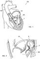
- Figures 1 to 8 illustrate a material for treating a heart valve, in particular a mitral valve 101 of a heart 100 (cf. figure 1 ), which comprises a first catheter 1, diagrammatically illustrated in figure 2 , and a second catheter diagrammatically illustrated in any of figures 3 to 12 .
- the first catheter 1 is introduced through the aorta 102, then bears against the heart wall at the ventricle 103 and is directed such that its free end is positioned at the valve 101, immediately below the annulus 104 thereof, as shown by figure 2 .
- Said catheter 1 contains a hollow needle 5 which, once the catheter has been positioned, is slid into the catheter 1 until it goes through the annulus 104. A guidance wire 6 is then slid inside the needle 5 until it goes past the auricular side of the valve 101.
- the catheter 1 is then removed from the heart 100, without removing the wire 6, then the catheter 2 is introduced along said wire 6 until it in turn arrives against the valve 101 of the ventricular side (cf. figures 3 and 4 ).
- said catheter 2 contains two deployable guide members 10, 11, an implant 12 having a helical shape and an actuating rod 13 connected to one end of the implant 12 with a rotating connection (for clarity of the drawing, the body of the catheter 2 is shown as being transparent).
- the guide member 10 is tubular and is engaged on the wire 6, thus making it possible to guide the catheter 2 to the aforementioned position. It appears in figure 4 that this guide member 10 is designed to be engaged on the auricular side of the valve 101, through the hole 105 previously made by the needle 5.
- the other guide member 11 is not tubular and is engaged in a lateral zone of the catheter 2, leading to the outside through a lateral opening 15 separate from the main end opening 16 of said catheter 2. Said guide member 11 is designed to be engaged on the ventricular side of the valve 101, through said lateral opening 15.
- the distal part 10a of the guide member 10 intended to be deployed from the auricular side of the valve 101 is in a shape memory material. As shown in figure 5 , once deployed, it assumes a bent shape, by shape memory.
- the guide members 10 and 11 can be rotated relative to the catheter 2, along the axis of said catheter 2, such that, by this rotational movement, their parts 10a, 11a deployed outside the catheter 2 can be engaged at the bottom of the above-annular and sub-annular groove formed by the annulus 104 of the valve 101.
- Figure 5 also shows that the guide member 10 can, once its distal portion 10a has adopted said bent shape, be slid into the catheter 2 in the proximal direction while the guide member 11 is either kept in position or slid in this same catheter 2 in the distal direction.
- the result, as shown in figure 6 is pinching of the valve tissue 101, along the annulus 104, which ensures that the catheter 2 is held perfectly in position.
- the implant 12 is engaged both around the guide member 10 and around the guide member 11. Once the aforementioned immobilization of the catheter 2 has taken place, the implant 12 is moved forward using the rod 13 and is simultaneously driven in rotation in the direction of screwing of its coils. The distal end of this implant 12 is self-tapping, such that the implant 12 penetrates the tissue forming the annulus 104 (cf. figure 6 ).
- Figure 7 shows that the implant 12 is thus “screwed” into the tissue of the annulus 104 until an abutment 20 located at the proximal end of the implant 12 meets the tissue of the annulus 104.
- the rod 13 is connected to this abutment 20 with separation possibility, for example by a releasable snap-locking arrangement and, once the implant 12 has been completely placed (cf. figure 8 ), suitable tension is exerted on the rod 13 so as to separate it from the abutment 20.
- the implant 12 is in a shape memory material and is such that before heating by the patient's organism, it adopts a longitudinally extended shape and once heated by the organism, it contracts longitudinally, the pitch of its coils decreasing, as appears in figure 8 .
- This reduction in pitch makes it possible to contract the tissue of the annulus 104, which performs, in whole or in part, an annuloplasty, i.e. a reduction of a distention of the annulus 104.
- the guide members 10 and 11 are removed by sliding, then the catheter 2 is removed, as is the guidance wire 6.
- Figures 9 to 12 show, very diagrammatically, another embodiment of the material according to the invention, in which the implant 12 has a substantially invariable length.
- the guide members 10 and 11 were not illustrated.
- the catheter 2 and the actuating rod 13 comprise respective abutment surfaces 22 and 23, which meet at the end of introduction of the implant 12 in the annulus 104, this meeting blocking the forward motion of the implant 12, but not preventing said implant 12 from being driven in rotation along its axis.
- the implant 12 is introduced into the annulus 104, until the abutment 23 arrives against the abutment 22 (cf. figure 10 ); the abutment 20 is, in this embodiment, equipped with anchors 20a able to penetrate the tissue of the annulus 104 and, in this same position, these anchors 20a are found near the wall of the annulus 104, but without penetrating said wall.
- Rotation of the implant 12 along its axis is then continued, which, in light of the longitudinal immobilization of said implant 12, causes movement, in the proximal direction of the catheter 2, of portions of the annulus 104 gone through by the respective coils of the implant 12.
- This movement makes it possible to compress the tissue forming said annulus 104 and, simultaneously, to cause the anchors 20a to penetrate the wall of this tissue, ensuring the immobilization of the implant 12 in rotation (cf. figure 11 ).
- the abutment 20 can then be separated from the rod 13, as previously described (cf. figure 12 ).
- Figures 13 and 14 show a third embodiment of the material according to the invention, in which the implant 12 comprises coils having an inconsistent pitch, this pitch being larger at the coils 12a located in the distal part of the implant 12 and smaller at the coils 12b located in the proximal part of this implant.
- the proximal coils 12b having the smaller pitch contract the portion of the annulus 104 wherein the distal coils having the larger pitch were previously engaged, thereby causing this portion of the annulus 104 to contract and thus performing an annuloplasty.
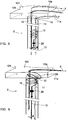
- Figures 15 and 16 show a variation of an embodiment of the material, in which the catheter 2 comprises, in addition to the guide members 10 and 11, a third guide member 25, diametrically opposite the guide member 11.
- This guide member 25 can be deployed through an opening 26 of said catheter 2 diametrically opposite the opening 15.
- the invention provides a material for treating a heart valve, in particular a mitral valve of a heart, that is fully satisfactory and makes it possible to conduct either annuloplasties or reinforcements of the valve annulus under optimal conditions.
Landscapes
- Health & Medical Sciences (AREA)
- Cardiology (AREA)
- Life Sciences & Earth Sciences (AREA)
- Engineering & Computer Science (AREA)
- Public Health (AREA)
- Biomedical Technology (AREA)
- Heart & Thoracic Surgery (AREA)
- Veterinary Medicine (AREA)
- Animal Behavior & Ethology (AREA)
- General Health & Medical Sciences (AREA)
- Surgery (AREA)
- Vascular Medicine (AREA)
- Oral & Maxillofacial Surgery (AREA)
- Transplantation (AREA)
- Nuclear Medicine, Radiotherapy & Molecular Imaging (AREA)
- Medical Informatics (AREA)
- Molecular Biology (AREA)
- Prostheses (AREA)
Description
- The present invention relates to a material for treating a heart valve, in particular a mitral valve of a heart. This treatment may consist of performing an annuloplasty, i.e. decreasing distention of the annulus, or of strengthening the annulus of a normal valve. The invention also relates to a percutaneous method for performing a treatment of this type.
- The annulus of a heart valve may, over time, be subject to distention leading to poor coaptation of the leaflets, resulting in decreased sealing of the valve.
- To treat this ailment, it is well-known to perform an annuloplasty, i.e. a recalibration of the annulus using a member implanted on the valve annulus.
- This annuloplasty member may be a prosthetic annulus fixed on the native valve annulus. This technique, however, has the drawback of involving open-heart surgery.
- The annuloplasty member may also be a deformable member, able to be introduced using a catheter through minimally-invasive vascular access, then able to be delivered through the catheter and fixed near the valve annulus before being circumferentially withdrawn.
- The existing annuloplasty members of this type, and the corresponding implantation techniques, like systems using the coronary sinuses, are not, however, fully satisfactory.
- Moreover, it may be necessary to implant a prosthetic heart valve, in particular percutaneously using a catheter. Currently, this type of percutaneous implantation is difficult on the mitral valve of a heart, due essentially to the fact that the annulus of a mitral valve is elastic and may be distended during percutaneous implantation of a prosthetic valve.
- The present invention essentially aims to resolve the drawbacks and gaps of the earlier techniques.
-
WO 2005/087139 A1 , according to its abstract, relates to a device for treating valve failure that has one or more engaging zones for engaging the device with the annulus of the valve being treated, and also has pre-disposition means for changing the geometry of the device to a predetermined configuration, and is compressible for percutaneous delivery to the valve. - The concerned material comprises, in a known manner, an annuloplasty member able to be introduced using a catheter through minimally invasive vascular access, then to be delivered by said catheter and fixed to the valve annulus.
- The material according to the invention is defined in
claim 1. - The material according to the invention thus allows the implant to be placed very precisely along a segment of the valve annulus, using minimally-invasive access. The guide member is retracted into the catheter after placement of the implant, only the latter part remaining in place at the valve annulus.
- The implant may vary in length and can adopt an extended shape for introduction and a shortened shape for implantation, the passage of the implant to this shortened implantation shape making it possible to gather the valve annulus portion in which said implant is placed.
- In this case, the implant allows performance of an annuloplasty.
- For passage of the implant from its extended shape to its shortened shape, said implant is preferably made of a shape memory material. This implant may in particular be in a nickel and titanium alloy known by the name "nitinol".
- The implant can also have an invariable or slightly variable length. The implant can then be used to prevent distention of the valve annulus portion in which it is implanted, and/or to form a stiff annular or semi-annular frame, making it possible to implant and anchor a prosthetic valve percutaneously, in particular a prosthetic valve placed on a deployable stent. The implant can also be used to perform an annuloplasty, said actuation means then comprising an abutment integral with the implant and an abutment integral with the catheter; once the implant has been deployed, the abutment integral with the implant meets the abutment integral with the catheter and thus limits the longitudinal progress of the implant without limiting the rotation of said implant; continuing rotation of the implant around its axis after this longitudinal progress limitation causes gathering of the annulus portion in which the implant is placed.
- The implant can comprise coils having a uniform pitch. It can also comprise coils having a varied pitch, said pitch being greater at the distal part of the implant and smaller at the proximal part of the implant. During screwing of an implant of this type in the valve annulus, the proximal coils having the smaller pitch contract the portion of the annulus wherein the distal coils having the greater pitch were previously engaged, thereby causing this portion of the annulus to contract and thus performing an annuloplasty.
- The aforementioned means for actuating the implant comprises a rod rotationally connected to the implant, this connection being releasable to allow, after placement of the implant, separation of said implant from said rod. This releasable connection may in particular consist of a releasable snap-locking arrangement of the rod and the implant, said arrangement being released through axial tension exerted on the rod so as to separate it from the corresponding end of the implant; this can also be done by unscrewing, or other similar releasable connection means.
- Preferably, each guide member is connected to means for its actuation making it possible to rotate the guide member in relation to the catheter.
- This rotation makes it possible to ensure that each guide member is indeed engaged along the edge of the valve annulus connected to the wall comprising said annulus.
The catheter contains two deployable guide members as previously mentioned, a first of which can be engaged on one side of the valve and the second of which can be engaged on the other side of the valve, and the implant is engaged around these two guide members. - In this way, the implant is guided during its placement by these two guide members, on the two surfaces of the valve annulus.
- Preferably, in this case, the guide member, which is found, once deployed, on the other surface of the valve relative to the catheter, may comprise a bearing portion able to bear against the surface of the valve opposite the catheter, making it possible to pinch this tissue between it and the end of the catheter.
- This pinching makes it possible to ensure stable positioning of the catheter during deployment of the implant.
- This bearing portion may be formed in particular by a distal portion of the guide member, designed to be deployed, which is connected by a bent portion to a proximal portion of the guide member intended to remain in the catheter, said bent portion allowing, after deployment, orientation of said distal portion substantially in the plane of the valve annulus.
- This bent portion may in particular be generated by shape memory, then able to be made of "nitinol".
- The implant can be placed from the commissure formed by two leaflets adjacent to the treated valve; in this case, when a guide member contained by the catheter must be deployed on the surface of the valve opposite the catheter, this deployment can be done by going through this commissure.
- The implant can also be placed outside a commissure of this type, in which case the catheter, or another catheter comprised by the material, includes a piercing needle for the valve annulus. In particular, in this case, the material comprises:
- a first catheter containing said piercing needle, which is hollow;
- a guidance wire able to be slid through the needle;
- a second catheter, containing the aforementioned guide member(s) and implant, the guide member intended to extend on the surface of the valve opposite the second catheter being tubular and engaged on the guidance wire.
- The first catheter makes it possible to perform the piercing and deploy the guidance wire; said guidance wire is left in place and said first catheter and the needle are removed; the second catheter is then introduced while being guided by the guidance wire; said guidance wire makes it possible to guide the guide member during its deployment.
The material comprises two guide members that may each intended to be engaged on one of the surfaces of the valve or the valve annulus, as described above, the guide member intended to be engaged on the surface of the valve opposite the catheter advantageously being tubular and being engaged on this guidance wire. - Positioning of the catheter and engagement of the guide member on the surface of the valve opposite the catheter are thus done under optimal conditions.
- According to one particular embodiment of the invention, the material comprises a guide member positioned such that it can be deployed on one side of the catheter diametrically opposite that on which another guide member is deployed.
- These diametrically opposed guide members make it possible to ensure perfect positioning of the catheter as close as possible to the valve annulus, without rotating the guide members relative to the catheter, these two diametrically opposed guide members allowing self-shifting of the materials along the wall to which the annulus is connected.
A percutaneous operating method described herein comprises steps consisting of: - using at least one catheter, comprising:
- at least one guide member able to be deployed from said catheter so as to extend along a portion of the valve annulus of the valve, in the immediate vicinity of said valve annulus, and
- an implant having a helical shape engaged on said guide member, connected, with the possibility of being separated, to actuation means making it possible to move said implant forward while driving it in rotation along its axis;
- deploying the implant from the catheter by causing said implant to move forward and driving it in rotation along its axis, said rotation allowing the implant to penetrate the tissue of the valve annulus while being guided along said annulus by said guide member.
- The implant used may be longitudinally compressible and can adopt an extended introduction form and a shortened form making it possible to reduce the length of the annulus portion in which it is implanted.
- The implant used can also have an invariable or slightly variable length, longitudinally.
- In this case, the method may comprise a step consisting, after placement of the implant, of percutaneously implanting and anchoring a prosthetic valve.
- The implant used may also comprise coils having an inconstant pitch, said pitch being larger at the distal part of the implant and smaller at the proximal part of said implant.
- The method described herein may also comprise steps consisting of:
- deploying a first guide member and a second guide member, on the surface of the valve facing the catheter and on the surface of the valve opposite the catheter, respectively;
- positioning the two guide members in relation to each other so as to hold the valve tissue between the guide members.
- The method according to the invention may also comprise steps consisting of:
- introducing the catheter at the commissure formed by two leaflets adjacent to the valve, and
- deploying a deployable member through said commissure.
- The method described herein may also comprise steps consisting of:
- introducing, outside the commissures formed by the leaflets of the valve, a catheter including a piercing needle for the valve annulus;
- piercing the valve annulus using said needle;
- removing the needle and deploying, through the hole made by said needle, a guide member designed to be placed on the side of the valve opposite the catheter.
- In this case, the method may in particular comprise steps consisting of:
- piercing said hole using a first catheter containing said needle;
- introducing, after piercing said hole, a guidance wire through this hole;
- leaving this guidance wire in place and removing said first catheter as well as the needle;
- introducing a second catheter, containing the aforementioned guidance wire(s) and implant, one of the guide members being tubular and engaged on the guidance wire.
- The invention will be well-understood, and other characteristics and advantages thereof will appear, in reference to the appended diagrammatic drawing, illustrating, as non-limiting examples, several possible embodiments of the material it concerns.
-
Figure 1 is a partial cross-section of a heart, in which a first catheter is introduced up to the mitral valve; -
figure 2 is a cross-section of this valve, after piercing of a hole through the valve annulus, and of the first catheter; -
figures 3 to 8 are diagrammatic views of the material according to a first embodiment, and of a portion of the mitral valve, during the various successive steps in placing an implant to treat this valve; -
figures 9 to 12 are very simplified diagrammatic views of four steps in placing the implant according to a second embodiment; -
figures 13 and 14 are principle views of two steps in placing an implant according to another embodiment, and -
figures 15 and 16 are very simplified diagrammatic views, perspective and top views, respectively, of the material according to yet another embodiment. - For simplification, the parts or elements of one embodiment which are found identically or similarly in another embodiment will be identified using the same numeric references and will not be described again.
-
Figures 1 to 8 illustrate a material for treating a heart valve, in particular amitral valve 101 of a heart 100 (cf.figure 1 ), which comprises afirst catheter 1, diagrammatically illustrated infigure 2 , and a second catheter diagrammatically illustrated in any offigures 3 to 12 . - As shown in
figure 1 , thefirst catheter 1 is introduced through theaorta 102, then bears against the heart wall at theventricle 103 and is directed such that its free end is positioned at thevalve 101, immediately below theannulus 104 thereof, as shown byfigure 2 . -
Said catheter 1 contains ahollow needle 5 which, once the catheter has been positioned, is slid into thecatheter 1 until it goes through theannulus 104. Aguidance wire 6 is then slid inside theneedle 5 until it goes past the auricular side of thevalve 101. - The
catheter 1 is then removed from theheart 100, without removing thewire 6, then thecatheter 2 is introduced along saidwire 6 until it in turn arrives against thevalve 101 of the ventricular side (cf.figures 3 and 4 ). - As shown by these
figures 3 and 4 , saidcatheter 2 contains twodeployable guide members implant 12 having a helical shape and anactuating rod 13 connected to one end of theimplant 12 with a rotating connection (for clarity of the drawing, the body of thecatheter 2 is shown as being transparent). - The
guide member 10 is tubular and is engaged on thewire 6, thus making it possible to guide thecatheter 2 to the aforementioned position. It appears infigure 4 that thisguide member 10 is designed to be engaged on the auricular side of thevalve 101, through thehole 105 previously made by theneedle 5. - The
other guide member 11 is not tubular and is engaged in a lateral zone of thecatheter 2, leading to the outside through alateral opening 15 separate from the main end opening 16 of saidcatheter 2. Saidguide member 11 is designed to be engaged on the ventricular side of thevalve 101, through saidlateral opening 15. - The
distal part 10a of theguide member 10 intended to be deployed from the auricular side of thevalve 101 is in a shape memory material. As shown infigure 5 , once deployed, it assumes a bent shape, by shape memory. - It is shown in this
figure 5 that theguide members catheter 2, along the axis of saidcatheter 2, such that, by this rotational movement, theirparts catheter 2 can be engaged at the bottom of the above-annular and sub-annular groove formed by theannulus 104 of thevalve 101.Figure 5 also shows that theguide member 10 can, once itsdistal portion 10a has adopted said bent shape, be slid into thecatheter 2 in the proximal direction while theguide member 11 is either kept in position or slid in thissame catheter 2 in the distal direction. The result, as shown infigure 6 , is pinching of thevalve tissue 101, along theannulus 104, which ensures that thecatheter 2 is held perfectly in position. - As shown in
figures 3 to 8 , theimplant 12 is engaged both around theguide member 10 and around theguide member 11. Once the aforementioned immobilization of thecatheter 2 has taken place, theimplant 12 is moved forward using therod 13 and is simultaneously driven in rotation in the direction of screwing of its coils. The distal end of thisimplant 12 is self-tapping, such that theimplant 12 penetrates the tissue forming the annulus 104 (cf.figure 6 ). -
Figure 7 shows that theimplant 12 is thus "screwed" into the tissue of theannulus 104 until anabutment 20 located at the proximal end of theimplant 12 meets the tissue of theannulus 104. - The
rod 13 is connected to thisabutment 20 with separation possibility, for example by a releasable snap-locking arrangement and, once theimplant 12 has been completely placed (cf.figure 8 ), suitable tension is exerted on therod 13 so as to separate it from theabutment 20. - In the embodiment shown in
figures 3 to 8 , theimplant 12 is in a shape memory material and is such that before heating by the patient's organism, it adopts a longitudinally extended shape and once heated by the organism, it contracts longitudinally, the pitch of its coils decreasing, as appears infigure 8 . This reduction in pitch makes it possible to contract the tissue of theannulus 104, which performs, in whole or in part, an annuloplasty, i.e. a reduction of a distention of theannulus 104. - After placement of the
implant 12, theguide members catheter 2 is removed, as is theguidance wire 6. -
Figures 9 to 12 show, very diagrammatically, another embodiment of the material according to the invention, in which theimplant 12 has a substantially invariable length. For clarity of the drawing, theguide members - In this case, the
catheter 2 and theactuating rod 13 comprise respective abutment surfaces 22 and 23, which meet at the end of introduction of theimplant 12 in theannulus 104, this meeting blocking the forward motion of theimplant 12, but not preventing saidimplant 12 from being driven in rotation along its axis. - From the position shown in
figure 9 , theimplant 12 is introduced into theannulus 104, until theabutment 23 arrives against the abutment 22 (cf.figure 10 ); theabutment 20 is, in this embodiment, equipped withanchors 20a able to penetrate the tissue of theannulus 104 and, in this same position, theseanchors 20a are found near the wall of theannulus 104, but without penetrating said wall. - Rotation of the
implant 12 along its axis is then continued, which, in light of the longitudinal immobilization of saidimplant 12, causes movement, in the proximal direction of thecatheter 2, of portions of theannulus 104 gone through by the respective coils of theimplant 12. This movement makes it possible to compress the tissue forming saidannulus 104 and, simultaneously, to cause theanchors 20a to penetrate the wall of this tissue, ensuring the immobilization of theimplant 12 in rotation (cf.figure 11 ). - The
abutment 20 can then be separated from therod 13, as previously described (cf.figure 12 ). -
Figures 13 and 14 show a third embodiment of the material according to the invention, in which theimplant 12 comprises coils having an inconsistent pitch, this pitch being larger at thecoils 12a located in the distal part of theimplant 12 and smaller at thecoils 12b located in the proximal part of this implant. - As can be understood from comparing
figures 13 and 14 , during screwing of theimplant 12 into theannulus 104, theproximal coils 12b having the smaller pitch contract the portion of theannulus 104 wherein the distal coils having the larger pitch were previously engaged, thereby causing this portion of theannulus 104 to contract and thus performing an annuloplasty. -
Figures 15 and 16 show a variation of an embodiment of the material, in which thecatheter 2 comprises, in addition to theguide members third guide member 25, diametrically opposite theguide member 11. Thisguide member 25 can be deployed through anopening 26 of saidcatheter 2 diametrically opposite theopening 15. - These two
guide members catheter 2 as close as possible to theannulus 104, as shown infigure 16 . - As appears from the preceding, the invention provides a material for treating a heart valve, in particular a mitral valve of a heart, that is fully satisfactory and makes it possible to conduct either annuloplasties or reinforcements of the valve annulus under optimal conditions.
- It goes without saying that the invention is not limited to the embodiment described above as an example, but that it extends to all forms of embodiments covered by the appended claims.
Claims (13)
- Material for treating a heart valve, in particular a mitral valve (101), comprising an annuloplasty member (12) able to be introduced using a catheter (2) through minimally invasive vascular access, then to be delivered by said catheter and fixed to the valve annulus (104), characterized in that it includes at least one catheter (2) comprising:- two guide members (10, 11) able to be deployed from said catheter (2) such that they extend along portions of the valve annulus (104) of the valve (101), in the immediate proximity of said valve annulus, wherein the first guide member can be engaged on one side of the valve (101) and the second guide member can be engaged on the other side of the valve (101), and- an implant (12) having a helical shape engaged on said guide members (10, 11), connected, with separation possibility, to actuation means (13, 20 ; 22, 23) making it possible to cause this implant (12) to move forward while driving it in rotation around its axis; the implant (12) can thus be deployed from the catheter (2) while being simultaneously moved forward and driven in rotation along its axis, said rotation enabling the implant (12) to penetrate the tissue of the valve annulus (104) while being guided along said annulus by said guide members (10, 11), wherein the implant is engaged around these two guide members.
- Material according to claim 1, characterized in that the implant (12) varies in length and that it can adopt an extended shape for introduction and a shortened shape for implantation, the passage of the implant (12) to this shortened implantation shape making it possible to gather the valve annulus (104) portion in which said implant (12) is placed.
- Material according to claim 2, characterized in that the implant (12) is made of a shape memory material.
- Material according to claim 1, characterized in that the implant (12) has an invariable or slightly variable length.
- Material according to claim 1, characterized in that the implant (12) comprises coils having a uniform pitch.
- Material according to claim 1, characterized in that the implant (12) comprises coils (12a, 12b) having a varied pitch, said pitch being greater at the distal part of the implant (12) and smaller at the proximal part of the implant.
- Material according to claim 4, characterized in that said actuation means comprises an abutment (23) integral with the implant (12) and an abutment (22) integral with the catheter (2); once the implant (12) has been deployed, the abutment (23) integral with the implant (12) meets the abutment (22) integral with the catheter (2) and thus limiting the longitudinal progress of the implant (12) without limiting the rotation of said implant; continuing rotation of the implant (12) around its axis after this longitudinal progress limitation causes gathering of the annulus portion (104) in which the implant (12) is placed.
- Material according to any of claims 1 to 7, characterized in that each guide member (10, 11) is connected to means for its actuation making it possible to rotate the guide members (10, 11) in relation to the catheter (2).
- Material according to claim 1, characterized in that the guide member (10), which is found, once deployed, on the other surface of the valve (101) relative to the catheter (2), comprises a bearing portion (10a) able to bear against the surface of the valve (101) opposite the catheter (2), making it possible to pinch this tissue between it and the end of the catheter (2).
- Material according to claim 9, characterized in that said bearing portion is formed by a distal portion (10a) of the guide member (10), designed to be deployed, which is connected by a bent portion to a proximal portion of the guide member (10) intended to remain in the catheter (2), said bent portion allowing, after deployment, orientation of said distal portion (10a) substantially in the plane of the valve annulus (104).
- Material according to any of claims 1 to 10, characterized in that the catheter, or another catheter (1) comprised by the material, includes a piercing needle (5) for the valve annulus (104).
- Material according to claim 11, characterized in that it comprises:- a first catheter (1) containing said piercing needle (5), which is hollow;- a guidance wire (6) able to be slid through the needle (5);- a second catheter (2), containing the two guide members (10, 11), each intended to be engaged on one of the surfaces of the valve (101), and implant (12), the guide member (10) intended to extend on the surface of the valve (101) opposite the second catheter (2) being tubular and engaged on the guidance wire (6).
- Material according to claim 12, characterized in that it comprises a guide member (25) positioned such that it can be deployed on one side of the catheter (2) diametrically opposite that on which another guide member (11) is deployed.
Priority Applications (1)
| Application Number | Priority Date | Filing Date | Title |
|---|---|---|---|
| EP19161192.0A EP3527171A1 (en) | 2006-12-22 | 2007-12-18 | Material for treatment of a heart valve, in particular a mitral valve |
Applications Claiming Priority (3)
| Application Number | Priority Date | Filing Date | Title |
|---|---|---|---|
| US87654706P | 2006-12-22 | 2006-12-22 | |
| FR0611284A FR2910269B1 (en) | 2006-12-22 | 2006-12-22 | TREATMENT EQUIPMENT FOR A CARDIAC VALVE, IN PARTICULAR A MITRAL VALVE |
| PCT/IB2007/003975 WO2008081256A1 (en) | 2006-12-22 | 2007-12-18 | Material for treatment of a heart valve, in particular a mitral valve |
Related Child Applications (1)
| Application Number | Title | Priority Date | Filing Date |
|---|---|---|---|
| EP19161192.0A Division EP3527171A1 (en) | 2006-12-22 | 2007-12-18 | Material for treatment of a heart valve, in particular a mitral valve |
Publications (2)
| Publication Number | Publication Date |
|---|---|
| EP2120794A1 EP2120794A1 (en) | 2009-11-25 |
| EP2120794B1 true EP2120794B1 (en) | 2019-03-13 |
Family
ID=38255558
Family Applications (2)
| Application Number | Title | Priority Date | Filing Date |
|---|---|---|---|
| EP07866565.0A Not-in-force EP2120794B1 (en) | 2006-12-22 | 2007-12-18 | Material for treatment of a heart valve, in particular a mitral valve |
| EP19161192.0A Withdrawn EP3527171A1 (en) | 2006-12-22 | 2007-12-18 | Material for treatment of a heart valve, in particular a mitral valve |
Family Applications After (1)
| Application Number | Title | Priority Date | Filing Date |
|---|---|---|---|
| EP19161192.0A Withdrawn EP3527171A1 (en) | 2006-12-22 | 2007-12-18 | Material for treatment of a heart valve, in particular a mitral valve |
Country Status (5)
| Country | Link |
|---|---|
| US (3) | US9232942B2 (en) |
| EP (2) | EP2120794B1 (en) |
| ES (1) | ES2729201T3 (en) |
| FR (1) | FR2910269B1 (en) |
| WO (1) | WO2008081256A1 (en) |
Cited By (18)
| Publication number | Priority date | Publication date | Assignee | Title |
|---|---|---|---|---|
| US10856984B2 (en) | 2017-08-25 | 2020-12-08 | Neovasc Tiara Inc. | Sequentially deployed transcatheter mitral valve prosthesis |
| US10940001B2 (en) | 2012-05-30 | 2021-03-09 | Neovasc Tiara Inc. | Methods and apparatus for loading a prosthesis onto a delivery system |
| US11311376B2 (en) | 2019-06-20 | 2022-04-26 | Neovase Tiara Inc. | Low profile prosthetic mitral valve |
| US11357622B2 (en) | 2016-01-29 | 2022-06-14 | Neovase Tiara Inc. | Prosthetic valve for avoiding obstruction of outflow |
| US11389291B2 (en) | 2013-04-04 | 2022-07-19 | Neovase Tiara Inc. | Methods and apparatus for delivering a prosthetic valve to a beating heart |
| US11413139B2 (en) | 2011-11-23 | 2022-08-16 | Neovasc Tiara Inc. | Sequentially deployed transcatheter mitral valve prosthesis |
| US11419720B2 (en) | 2010-05-05 | 2022-08-23 | Neovasc Tiara Inc. | Transcatheter mitral valve prosthesis |
| US11464631B2 (en) | 2016-11-21 | 2022-10-11 | Neovasc Tiara Inc. | Methods and systems for rapid retraction of a transcatheter heart valve delivery system |
| US11491006B2 (en) | 2019-04-10 | 2022-11-08 | Neovasc Tiara Inc. | Prosthetic valve with natural blood flow |
| US11497602B2 (en) | 2012-02-14 | 2022-11-15 | Neovasc Tiara Inc. | Methods and apparatus for engaging a valve prosthesis with tissue |
| US11602429B2 (en) | 2019-04-01 | 2023-03-14 | Neovasc Tiara Inc. | Controllably deployable prosthetic valve |
| US11737872B2 (en) | 2018-11-08 | 2023-08-29 | Neovasc Tiara Inc. | Ventricular deployment of a transcatheter mitral valve prosthesis |
| US11779742B2 (en) | 2019-05-20 | 2023-10-10 | Neovasc Tiara Inc. | Introducer with hemostasis mechanism |
| US11944537B2 (en) | 2017-01-24 | 2024-04-02 | 4C Medical Technologies, Inc. | Systems, methods and devices for two-step delivery and implantation of prosthetic heart valve |
| US11998447B2 (en) | 2019-03-08 | 2024-06-04 | Neovasc Tiara Inc. | Retrievable prosthesis delivery system |
| US12029647B2 (en) | 2017-03-07 | 2024-07-09 | 4C Medical Technologies, Inc. | Systems, methods and devices for prosthetic heart valve with single valve leaflet |
| US12109111B2 (en) | 2015-12-15 | 2024-10-08 | Neovasc Tiara Inc. | Transseptal delivery system |
| US12544226B2 (en) | 2019-02-14 | 2026-02-10 | 4C Medical Technologies, Inc. | Hydrophilic skirt for paravalvular leak mitigation and fit and apposition optimization for prosthetic heart valve implants |
Families Citing this family (84)
| Publication number | Priority date | Publication date | Assignee | Title |
|---|---|---|---|---|
| US8016877B2 (en) | 1999-11-17 | 2011-09-13 | Medtronic Corevalve Llc | Prosthetic valve for transluminal delivery |
| US7018406B2 (en) | 1999-11-17 | 2006-03-28 | Corevalve Sa | Prosthetic valve for transluminal delivery |
| US8579966B2 (en) | 1999-11-17 | 2013-11-12 | Medtronic Corevalve Llc | Prosthetic valve for transluminal delivery |
| FR2826863B1 (en) | 2001-07-04 | 2003-09-26 | Jacques Seguin | ASSEMBLY FOR PLACING A PROSTHETIC VALVE IN A BODY CONDUIT |
| US7097659B2 (en) | 2001-09-07 | 2006-08-29 | Medtronic, Inc. | Fixation band for affixing a prosthetic heart valve to tissue |
| ITTO20040135A1 (en) | 2004-03-03 | 2004-06-03 | Sorin Biomedica Cardio Spa | CARDIAC VALVE PROSTHESIS |
| DE102005003632A1 (en) | 2005-01-20 | 2006-08-17 | Fraunhofer-Gesellschaft zur Förderung der angewandten Forschung e.V. | Catheter for the transvascular implantation of heart valve prostheses |
| ITTO20050074A1 (en) | 2005-02-10 | 2006-08-11 | Sorin Biomedica Cardio Srl | CARDIAC VALVE PROSTHESIS |
| US7914569B2 (en) | 2005-05-13 | 2011-03-29 | Medtronics Corevalve Llc | Heart valve prosthesis and methods of manufacture and use |
| US8764820B2 (en) | 2005-11-16 | 2014-07-01 | Edwards Lifesciences Corporation | Transapical heart valve delivery system and method |
| US11304800B2 (en) | 2006-09-19 | 2022-04-19 | Medtronic Ventor Technologies Ltd. | Sinus-engaging valve fixation member |
| US8876895B2 (en) | 2006-09-19 | 2014-11-04 | Medtronic Ventor Technologies Ltd. | Valve fixation member having engagement arms |
| US8834564B2 (en) | 2006-09-19 | 2014-09-16 | Medtronic, Inc. | Sinus-engaging valve fixation member |
| US8747459B2 (en) | 2006-12-06 | 2014-06-10 | Medtronic Corevalve Llc | System and method for transapical delivery of an annulus anchored self-expanding valve |
| US7871436B2 (en) | 2007-02-16 | 2011-01-18 | Medtronic, Inc. | Replacement prosthetic heart valves and methods of implantation |
| US7896915B2 (en) | 2007-04-13 | 2011-03-01 | Jenavalve Technology, Inc. | Medical device for treating a heart valve insufficiency |
| FR2915087B1 (en) * | 2007-04-20 | 2021-11-26 | Corevalve Inc | IMPLANT FOR TREATMENT OF A HEART VALVE, IN PARTICULAR OF A MITRAL VALVE, EQUIPMENT INCLUDING THIS IMPLANT AND MATERIAL FOR PLACING THIS IMPLANT. |
| US9848981B2 (en) | 2007-10-12 | 2017-12-26 | Mayo Foundation For Medical Education And Research | Expandable valve prosthesis with sealing mechanism |
| US8157853B2 (en) | 2008-01-24 | 2012-04-17 | Medtronic, Inc. | Delivery systems and methods of implantation for prosthetic heart valves |
| EP3572045B1 (en) | 2008-01-24 | 2022-12-21 | Medtronic, Inc. | Stents for prosthetic heart valves |
| US9149358B2 (en) | 2008-01-24 | 2015-10-06 | Medtronic, Inc. | Delivery systems for prosthetic heart valves |
| US9393115B2 (en) | 2008-01-24 | 2016-07-19 | Medtronic, Inc. | Delivery systems and methods of implantation for prosthetic heart valves |
| US9044318B2 (en) | 2008-02-26 | 2015-06-02 | Jenavalve Technology Gmbh | Stent for the positioning and anchoring of a valvular prosthesis |
| WO2011104269A1 (en) | 2008-02-26 | 2011-09-01 | Jenavalve Technology Inc. | Stent for the positioning and anchoring of a valvular prosthesis in an implantation site in the heart of a patient |
| US8430927B2 (en) | 2008-04-08 | 2013-04-30 | Medtronic, Inc. | Multiple orifice implantable heart valve and methods of implantation |
| ATE554731T1 (en) | 2008-05-16 | 2012-05-15 | Sorin Biomedica Cardio Srl | ATRAAUMATIC PROSTHETIC HEART VALVE PROSTHESIS |
| ES2551694T3 (en) | 2008-12-23 | 2015-11-23 | Sorin Group Italia S.R.L. | Expandable prosthetic valve with anchoring appendages |
| EP2628465A1 (en) | 2009-04-27 | 2013-08-21 | Sorin Group Italia S.r.l. | Prosthetic vascular conduit |
| US8439970B2 (en) | 2009-07-14 | 2013-05-14 | Edwards Lifesciences Corporation | Transapical delivery system for heart valves |
| US8808369B2 (en) | 2009-10-05 | 2014-08-19 | Mayo Foundation For Medical Education And Research | Minimally invasive aortic valve replacement |
| US9226826B2 (en) | 2010-02-24 | 2016-01-05 | Medtronic, Inc. | Transcatheter valve structure and methods for valve delivery |
| US8652204B2 (en) | 2010-04-01 | 2014-02-18 | Medtronic, Inc. | Transcatheter valve with torsion spring fixation and related systems and methods |
| US10856978B2 (en) | 2010-05-20 | 2020-12-08 | Jenavalve Technology, Inc. | Catheter system |
| IT1400327B1 (en) | 2010-05-21 | 2013-05-24 | Sorin Biomedica Cardio Srl | SUPPORT DEVICE FOR VALVULAR PROSTHESIS AND CORRESPONDING CORRESPONDENT. |
| CA2799459A1 (en) | 2010-05-25 | 2011-12-01 | Jenavalve Technology Inc. | Prosthetic heart valve and transcatheter delivered endoprosthesis comprising a prosthetic heart valve and a stent |
| WO2012087842A1 (en) | 2010-12-23 | 2012-06-28 | The Foundry, Llc | System for mitral valve repair and replacement |
| ES2641902T3 (en) | 2011-02-14 | 2017-11-14 | Sorin Group Italia S.R.L. | Sutureless anchoring device for cardiac valve prostheses |
| EP2486894B1 (en) | 2011-02-14 | 2021-06-09 | Sorin Group Italia S.r.l. | Sutureless anchoring device for cardiac valve prostheses |
| US9381082B2 (en) | 2011-04-22 | 2016-07-05 | Edwards Lifesciences Corporation | Devices, systems and methods for accurate positioning of a prosthetic valve |
| WO2012177942A2 (en) | 2011-06-21 | 2012-12-27 | Hanson Gifford, Iii | Prosthetic heart valve devices and associated systems and methods |
| US9655722B2 (en) | 2011-10-19 | 2017-05-23 | Twelve, Inc. | Prosthetic heart valve devices, prosthetic mitral valves and associated systems and methods |
| CN103889369B (en) | 2011-10-19 | 2016-09-14 | 托尔福公司 | device for cardiac valve replacement |
| JP6133309B2 (en) | 2011-10-19 | 2017-05-24 | トゥエルヴ, インコーポレイテッド | Prosthetic heart valve device |
| US11202704B2 (en) | 2011-10-19 | 2021-12-21 | Twelve, Inc. | Prosthetic heart valve devices, prosthetic mitral valves and associated systems and methods |
| US9039757B2 (en) | 2011-10-19 | 2015-05-26 | Twelve, Inc. | Prosthetic heart valve devices, prosthetic mitral valves and associated systems and methods |
| US9763780B2 (en) | 2011-10-19 | 2017-09-19 | Twelve, Inc. | Devices, systems and methods for heart valve replacement |
| EP2609893B1 (en) | 2011-12-29 | 2014-09-03 | Sorin Group Italia S.r.l. | A kit for implanting prosthetic vascular conduits |
| US9579198B2 (en) | 2012-03-01 | 2017-02-28 | Twelve, Inc. | Hydraulic delivery systems for prosthetic heart valve devices and associated methods |
| US10149757B2 (en) | 2013-03-15 | 2018-12-11 | Edwards Lifesciences Corporation | System and method for transaortic delivery of a prosthetic heart valve |
| WO2014179763A1 (en) | 2013-05-03 | 2014-11-06 | Medtronic Inc. | Valve delivery tool |
| CN105246431B (en) | 2013-05-20 | 2018-04-06 | 托尔福公司 | Implantable heart valve devices, mitral valve repair devices, and related systems and methods |
| CN105491978A (en) | 2013-08-30 | 2016-04-13 | 耶拿阀门科技股份有限公司 | Radially collapsible frame for a prosthetic valve and method for manufacturing such a frame |
| WO2015184138A1 (en) | 2014-05-29 | 2015-12-03 | Cardiaq Valve Technologies, Inc. | Prosthesis, delivery device and methods of use |
| EP3270825B1 (en) | 2015-03-20 | 2020-04-22 | JenaValve Technology, Inc. | Heart valve prosthesis delivery system |
| EP3632378B1 (en) | 2015-05-01 | 2024-05-29 | JenaValve Technology, Inc. | Device with reduced pacemaker rate in heart valve replacement |
| WO2017035002A1 (en) | 2015-08-21 | 2017-03-02 | Twelve Inc. | Implantable heart valve devices, mitral valve repair devices and associated systems and methods |
| CN109069272A (en) | 2016-04-29 | 2018-12-21 | 美敦力瓦斯科尔勒公司 | Prosthetic heart valve device with tethered anchor and associated systems and methods |
| US11065138B2 (en) | 2016-05-13 | 2021-07-20 | Jenavalve Technology, Inc. | Heart valve prosthesis delivery system and method for delivery of heart valve prosthesis with introducer sheath and loading system |
| US20200146854A1 (en) | 2016-05-16 | 2020-05-14 | Elixir Medical Corporation | Methods and devices for heart valve repair |
| US10653523B2 (en) | 2017-01-19 | 2020-05-19 | 4C Medical Technologies, Inc. | Systems, methods and devices for delivery systems, methods and devices for implanting prosthetic heart valves |
| CN110392557A (en) | 2017-01-27 | 2019-10-29 | 耶拿阀门科技股份有限公司 | Heart valve simulation |
| US10433961B2 (en) | 2017-04-18 | 2019-10-08 | Twelve, Inc. | Delivery systems with tethers for prosthetic heart valve devices and associated methods |
| US10702378B2 (en) | 2017-04-18 | 2020-07-07 | Twelve, Inc. | Prosthetic heart valve device and associated systems and methods |
| US10575950B2 (en) | 2017-04-18 | 2020-03-03 | Twelve, Inc. | Hydraulic systems for delivering prosthetic heart valve devices and associated methods |
| US10792151B2 (en) | 2017-05-11 | 2020-10-06 | Twelve, Inc. | Delivery systems for delivering prosthetic heart valve devices and associated methods |
| US10646338B2 (en) | 2017-06-02 | 2020-05-12 | Twelve, Inc. | Delivery systems with telescoping capsules for deploying prosthetic heart valve devices and associated methods |
| US10709591B2 (en) | 2017-06-06 | 2020-07-14 | Twelve, Inc. | Crimping device and method for loading stents and prosthetic heart valves |
| US12036113B2 (en) | 2017-06-14 | 2024-07-16 | 4C Medical Technologies, Inc. | Delivery of heart chamber prosthetic valve implant |
| US10786352B2 (en) | 2017-07-06 | 2020-09-29 | Twelve, Inc. | Prosthetic heart valve devices and associated systems and methods |
| US10729541B2 (en) | 2017-07-06 | 2020-08-04 | Twelve, Inc. | Prosthetic heart valve devices and associated systems and methods |
| US11285003B2 (en) | 2018-03-20 | 2022-03-29 | Medtronic Vascular, Inc. | Prolapse prevention device and methods of use thereof |
| US11026791B2 (en) | 2018-03-20 | 2021-06-08 | Medtronic Vascular, Inc. | Flexible canopy valve repair systems and methods of use |
| US12318289B2 (en) | 2018-05-23 | 2025-06-03 | Corcym S.R.L. | Device for the in-situ delivery of heart valve prosthesis |
| WO2019224577A1 (en) | 2018-05-23 | 2019-11-28 | Sorin Group Italia S.R.L. | A cardiac valve prosthesis |
| US11857441B2 (en) | 2018-09-04 | 2024-01-02 | 4C Medical Technologies, Inc. | Stent loading device |
| US11452628B2 (en) | 2019-04-15 | 2022-09-27 | 4C Medical Technologies, Inc. | Loading systems for collapsible prosthetic heart valve devices and methods thereof |
| WO2020214818A1 (en) * | 2019-04-16 | 2020-10-22 | Neochord, Inc. | Transverse helical cardiac anchor for minimally invasive heart valve repair |
| US11931253B2 (en) | 2020-01-31 | 2024-03-19 | 4C Medical Technologies, Inc. | Prosthetic heart valve delivery system: ball-slide attachment |
| US12133797B2 (en) | 2020-01-31 | 2024-11-05 | 4C Medical Technologies, Inc. | Prosthetic heart valve delivery system: paddle attachment feature |
| US12053375B2 (en) | 2020-03-05 | 2024-08-06 | 4C Medical Technologies, Inc. | Prosthetic mitral valve with improved atrial and/or annular apposition and paravalvular leakage mitigation |
| US11992403B2 (en) | 2020-03-06 | 2024-05-28 | 4C Medical Technologies, Inc. | Devices, systems and methods for improving recapture of prosthetic heart valve device with stent frame having valve support with inwardly stent cells |
| US12588998B1 (en) | 2022-09-01 | 2026-03-31 | 4C Medical Technologies, Inc. | Prosthetic heart valve for natural blood flow |
| US12171658B2 (en) | 2022-11-09 | 2024-12-24 | Jenavalve Technology, Inc. | Catheter system for sequential deployment of an expandable implant |
| US20240366366A1 (en) | 2023-03-24 | 2024-11-07 | 4C Medical Technologies, Inc. | Implant delivery |
Family Cites Families (11)
| Publication number | Priority date | Publication date | Assignee | Title |
|---|---|---|---|---|
| AU689096B2 (en) * | 1993-01-27 | 1998-03-26 | Intra Therapeutics, Inc. | Vascular and coronary stents |
| US7491232B2 (en) * | 1998-09-18 | 2009-02-17 | Aptus Endosystems, Inc. | Catheter-based fastener implantation apparatus and methods with implantation force resolution |
| US6419696B1 (en) * | 2000-07-06 | 2002-07-16 | Paul A. Spence | Annuloplasty devices and related heart valve repair methods |
| US7101395B2 (en) * | 2002-06-12 | 2006-09-05 | Mitral Interventions, Inc. | Method and apparatus for tissue connection |
| US7087064B1 (en) * | 2002-10-15 | 2006-08-08 | Advanced Cardiovascular Systems, Inc. | Apparatuses and methods for heart valve repair |
| US8512403B2 (en) * | 2003-05-20 | 2013-08-20 | The Cleveland Clinic Foundation | Annuloplasty ring with wing members for repair of a cardiac valve |
| US20050187568A1 (en) * | 2004-02-20 | 2005-08-25 | Klenk Alan R. | Devices and methods for closing a patent foramen ovale with a coil-shaped closure device |
| WO2005087139A1 (en) * | 2004-03-15 | 2005-09-22 | Baker Medical Research Institute | Treating valve failure |
| EP1853199B1 (en) * | 2005-02-28 | 2014-10-29 | Medtentia International Ltd Oy | Devices for improving the function of a heart valve |
| US7887476B2 (en) | 2005-11-10 | 2011-02-15 | Cianna Medical, Inc. | Helical brachytherapy apparatus and methods of using same |
| US20070118151A1 (en) * | 2005-11-21 | 2007-05-24 | The Brigham And Women's Hospital, Inc. | Percutaneous cardiac valve repair with adjustable artificial chordae |
-
2006
- 2006-12-22 FR FR0611284A patent/FR2910269B1/en not_active Expired - Fee Related
-
2007
- 2007-12-18 US US12/519,498 patent/US9232942B2/en active Active
- 2007-12-18 WO PCT/IB2007/003975 patent/WO2008081256A1/en not_active Ceased
- 2007-12-18 EP EP07866565.0A patent/EP2120794B1/en not_active Not-in-force
- 2007-12-18 ES ES07866565T patent/ES2729201T3/en active Active
- 2007-12-18 EP EP19161192.0A patent/EP3527171A1/en not_active Withdrawn
-
2015
- 2015-12-07 US US14/960,474 patent/US10478302B2/en active Active
-
2019
- 2019-10-29 US US16/666,494 patent/US20200060826A1/en not_active Abandoned
Non-Patent Citations (1)
| Title |
|---|
| None * |
Cited By (28)
| Publication number | Priority date | Publication date | Assignee | Title |
|---|---|---|---|---|
| US11419720B2 (en) | 2010-05-05 | 2022-08-23 | Neovasc Tiara Inc. | Transcatheter mitral valve prosthesis |
| US12611303B2 (en) | 2010-05-05 | 2026-04-28 | Neovasc Tiara Inc. | Transcatheter mitral valve prosthesis |
| US12053369B2 (en) | 2011-11-23 | 2024-08-06 | Neovasc Tiara Inc. | Sequentially deployed transcatheter mitral valve prosthesis |
| US11413139B2 (en) | 2011-11-23 | 2022-08-16 | Neovasc Tiara Inc. | Sequentially deployed transcatheter mitral valve prosthesis |
| US12138159B2 (en) | 2012-02-14 | 2024-11-12 | Neovasc Tiara Inc. | Methods and apparatus for engaging a valve prosthesis with tissue |
| US11497602B2 (en) | 2012-02-14 | 2022-11-15 | Neovasc Tiara Inc. | Methods and apparatus for engaging a valve prosthesis with tissue |
| US11617650B2 (en) | 2012-05-30 | 2023-04-04 | Neovasc Tiara Inc. | Methods and apparatus for loading a prosthesis onto a delivery system |
| US10940001B2 (en) | 2012-05-30 | 2021-03-09 | Neovasc Tiara Inc. | Methods and apparatus for loading a prosthesis onto a delivery system |
| US11389294B2 (en) | 2012-05-30 | 2022-07-19 | Neovasc Tiara Inc. | Methods and apparatus for loading a prosthesis onto a delivery system |
| US11389291B2 (en) | 2013-04-04 | 2022-07-19 | Neovase Tiara Inc. | Methods and apparatus for delivering a prosthetic valve to a beating heart |
| US12109111B2 (en) | 2015-12-15 | 2024-10-08 | Neovasc Tiara Inc. | Transseptal delivery system |
| US11357622B2 (en) | 2016-01-29 | 2022-06-14 | Neovase Tiara Inc. | Prosthetic valve for avoiding obstruction of outflow |
| US12193932B2 (en) | 2016-01-29 | 2025-01-14 | Neovasc Tiara Inc. | Prosthetic valve for avoiding obstruction of outflow |
| US11464631B2 (en) | 2016-11-21 | 2022-10-11 | Neovasc Tiara Inc. | Methods and systems for rapid retraction of a transcatheter heart valve delivery system |
| US12201524B2 (en) | 2016-11-21 | 2025-01-21 | Neovasc Tiara Inc. | Methods and systems for rapid retraction of a transcatheter heart valve delivery system |
| US11944537B2 (en) | 2017-01-24 | 2024-04-02 | 4C Medical Technologies, Inc. | Systems, methods and devices for two-step delivery and implantation of prosthetic heart valve |
| US12029647B2 (en) | 2017-03-07 | 2024-07-09 | 4C Medical Technologies, Inc. | Systems, methods and devices for prosthetic heart valve with single valve leaflet |
| US10856984B2 (en) | 2017-08-25 | 2020-12-08 | Neovasc Tiara Inc. | Sequentially deployed transcatheter mitral valve prosthesis |
| US11793640B2 (en) | 2017-08-25 | 2023-10-24 | Neovasc Tiara Inc. | Sequentially deployed transcatheter mitral valve prosthesis |
| US11737872B2 (en) | 2018-11-08 | 2023-08-29 | Neovasc Tiara Inc. | Ventricular deployment of a transcatheter mitral valve prosthesis |
| US12544226B2 (en) | 2019-02-14 | 2026-02-10 | 4C Medical Technologies, Inc. | Hydrophilic skirt for paravalvular leak mitigation and fit and apposition optimization for prosthetic heart valve implants |
| US11998447B2 (en) | 2019-03-08 | 2024-06-04 | Neovasc Tiara Inc. | Retrievable prosthesis delivery system |
| US11602429B2 (en) | 2019-04-01 | 2023-03-14 | Neovasc Tiara Inc. | Controllably deployable prosthetic valve |
| US12036117B2 (en) | 2019-04-10 | 2024-07-16 | Neovasc Tiara Inc. | Prosthetic valve with natural blood flow |
| US11491006B2 (en) | 2019-04-10 | 2022-11-08 | Neovasc Tiara Inc. | Prosthetic valve with natural blood flow |
| US11779742B2 (en) | 2019-05-20 | 2023-10-10 | Neovasc Tiara Inc. | Introducer with hemostasis mechanism |
| US11931254B2 (en) | 2019-06-20 | 2024-03-19 | Neovasc Tiara Inc. | Low profile prosthetic mitral valve |
| US11311376B2 (en) | 2019-06-20 | 2022-04-26 | Neovase Tiara Inc. | Low profile prosthetic mitral valve |
Also Published As
| Publication number | Publication date |
|---|---|
| US20100145439A1 (en) | 2010-06-10 |
| US10478302B2 (en) | 2019-11-19 |
| EP2120794A1 (en) | 2009-11-25 |
| FR2910269A1 (en) | 2008-06-27 |
| WO2008081256A1 (en) | 2008-07-10 |
| US9232942B2 (en) | 2016-01-12 |
| EP3527171A1 (en) | 2019-08-21 |
| FR2910269B1 (en) | 2009-02-27 |
| ES2729201T3 (en) | 2019-10-30 |
| US20200060826A1 (en) | 2020-02-27 |
| US20160151156A1 (en) | 2016-06-02 |
Similar Documents
| Publication | Publication Date | Title |
|---|---|---|
| US9232942B2 (en) | Material for treatment of a heart valve, in particular a mitral valve | |
| US9585754B2 (en) | Implant for treatment of a heart valve, in particular a mitral valve, material including such an implant, and material for insertion thereof | |
| JP7821205B2 (en) | Prosthetic Heart Valve Devices, Systems, and Methods | |
| EP3370649B1 (en) | Devices for reducing cardiac valve regurgitation | |
| EP3563805B1 (en) | Adjustable endolumenal mitral valve ring | |
| US20200390551A1 (en) | Transcatheter Annuloplasty System And Method | |
| US20220257373A1 (en) | Anchor for prosthetic cardiac valve delivery devices and systems | |
| EP1988851A2 (en) | Systems and methods for delivering a medical implant | |
| US12551345B2 (en) | Coil and barb anchors for heart valve repair devices | |
| WO2022047274A1 (en) | Prosthetic cardiac valve delivery systems and methods | |
| CN113692253A (en) | Systems and methods for delivering chordae replacement systems |
Legal Events
| Date | Code | Title | Description |
|---|---|---|---|
| PUAI | Public reference made under article 153(3) epc to a published international application that has entered the european phase |
Free format text: ORIGINAL CODE: 0009012 |
|
| 17P | Request for examination filed |
Effective date: 20090715 |
|
| AK | Designated contracting states |
Kind code of ref document: A1 Designated state(s): AT BE BG CH CY CZ DE DK EE ES FI FR GB GR HU IE IS IT LI LT LU LV MC MT NL PL PT RO SE SI SK TR |
|
| DAX | Request for extension of the european patent (deleted) | ||
| 17Q | First examination report despatched |
Effective date: 20120720 |
|
| GRAP | Despatch of communication of intention to grant a patent |
Free format text: ORIGINAL CODE: EPIDOSNIGR1 |
|
| STAA | Information on the status of an ep patent application or granted ep patent |
Free format text: STATUS: GRANT OF PATENT IS INTENDED |
|
| INTG | Intention to grant announced |
Effective date: 20180604 |
|
| GRAJ | Information related to disapproval of communication of intention to grant by the applicant or resumption of examination proceedings by the epo deleted |
Free format text: ORIGINAL CODE: EPIDOSDIGR1 |
|
| STAA | Information on the status of an ep patent application or granted ep patent |
Free format text: STATUS: EXAMINATION IS IN PROGRESS |
|
| INTC | Intention to grant announced (deleted) | ||
| GRAP | Despatch of communication of intention to grant a patent |
Free format text: ORIGINAL CODE: EPIDOSNIGR1 |
|
| STAA | Information on the status of an ep patent application or granted ep patent |
Free format text: STATUS: GRANT OF PATENT IS INTENDED |
|
| RAP1 | Party data changed (applicant data changed or rights of an application transferred) |
Owner name: MEDTRONIC CV LUXEMBOURG S.A R.L. |
|
| INTG | Intention to grant announced |
Effective date: 20181128 |
|
| GRAS | Grant fee paid |
Free format text: ORIGINAL CODE: EPIDOSNIGR3 |
|
| GRAA | (expected) grant |
Free format text: ORIGINAL CODE: 0009210 |
|
| STAA | Information on the status of an ep patent application or granted ep patent |
Free format text: STATUS: THE PATENT HAS BEEN GRANTED |
|
| AK | Designated contracting states |
Kind code of ref document: B1 Designated state(s): AT BE BG CH CY CZ DE DK EE ES FI FR GB GR HU IE IS IT LI LT LU LV MC MT NL PL PT RO SE SI SK TR |
|
| REG | Reference to a national code |
Ref country code: GB Ref legal event code: FG4D |
|
| REG | Reference to a national code |
Ref country code: CH Ref legal event code: EP Ref country code: AT Ref legal event code: REF Ref document number: 1106654 Country of ref document: AT Kind code of ref document: T Effective date: 20190315 |
|
| REG | Reference to a national code |
Ref country code: DE Ref legal event code: R096 Ref document number: 602007057856 Country of ref document: DE |
|
| REG | Reference to a national code |
Ref country code: IE Ref legal event code: FG4D |
|
| REG | Reference to a national code |
Ref country code: NL Ref legal event code: FP |
|
| REG | Reference to a national code |
Ref country code: LT Ref legal event code: MG4D |
|
| PG25 | Lapsed in a contracting state [announced via postgrant information from national office to epo] |
Ref country code: LT Free format text: LAPSE BECAUSE OF FAILURE TO SUBMIT A TRANSLATION OF THE DESCRIPTION OR TO PAY THE FEE WITHIN THE PRESCRIBED TIME-LIMIT Effective date: 20190313 Ref country code: FI Free format text: LAPSE BECAUSE OF FAILURE TO SUBMIT A TRANSLATION OF THE DESCRIPTION OR TO PAY THE FEE WITHIN THE PRESCRIBED TIME-LIMIT Effective date: 20190313 Ref country code: SE Free format text: LAPSE BECAUSE OF FAILURE TO SUBMIT A TRANSLATION OF THE DESCRIPTION OR TO PAY THE FEE WITHIN THE PRESCRIBED TIME-LIMIT Effective date: 20190313 |
|
| PG25 | Lapsed in a contracting state [announced via postgrant information from national office to epo] |
Ref country code: BG Free format text: LAPSE BECAUSE OF FAILURE TO SUBMIT A TRANSLATION OF THE DESCRIPTION OR TO PAY THE FEE WITHIN THE PRESCRIBED TIME-LIMIT Effective date: 20190613 Ref country code: LV Free format text: LAPSE BECAUSE OF FAILURE TO SUBMIT A TRANSLATION OF THE DESCRIPTION OR TO PAY THE FEE WITHIN THE PRESCRIBED TIME-LIMIT Effective date: 20190313 Ref country code: GR Free format text: LAPSE BECAUSE OF FAILURE TO SUBMIT A TRANSLATION OF THE DESCRIPTION OR TO PAY THE FEE WITHIN THE PRESCRIBED TIME-LIMIT Effective date: 20190614 |
|
| REG | Reference to a national code |
Ref country code: AT Ref legal event code: MK05 Ref document number: 1106654 Country of ref document: AT Kind code of ref document: T Effective date: 20190313 |
|
| REG | Reference to a national code |
Ref country code: ES Ref legal event code: FG2A Ref document number: 2729201 Country of ref document: ES Kind code of ref document: T3 Effective date: 20191030 |
|
| PG25 | Lapsed in a contracting state [announced via postgrant information from national office to epo] |
Ref country code: SK Free format text: LAPSE BECAUSE OF FAILURE TO SUBMIT A TRANSLATION OF THE DESCRIPTION OR TO PAY THE FEE WITHIN THE PRESCRIBED TIME-LIMIT Effective date: 20190313 Ref country code: EE Free format text: LAPSE BECAUSE OF FAILURE TO SUBMIT A TRANSLATION OF THE DESCRIPTION OR TO PAY THE FEE WITHIN THE PRESCRIBED TIME-LIMIT Effective date: 20190313 Ref country code: CZ Free format text: LAPSE BECAUSE OF FAILURE TO SUBMIT A TRANSLATION OF THE DESCRIPTION OR TO PAY THE FEE WITHIN THE PRESCRIBED TIME-LIMIT Effective date: 20190313 Ref country code: RO Free format text: LAPSE BECAUSE OF FAILURE TO SUBMIT A TRANSLATION OF THE DESCRIPTION OR TO PAY THE FEE WITHIN THE PRESCRIBED TIME-LIMIT Effective date: 20190313 Ref country code: PT Free format text: LAPSE BECAUSE OF FAILURE TO SUBMIT A TRANSLATION OF THE DESCRIPTION OR TO PAY THE FEE WITHIN THE PRESCRIBED TIME-LIMIT Effective date: 20190713 |
|
| PG25 | Lapsed in a contracting state [announced via postgrant information from national office to epo] |
Ref country code: PL Free format text: LAPSE BECAUSE OF FAILURE TO SUBMIT A TRANSLATION OF THE DESCRIPTION OR TO PAY THE FEE WITHIN THE PRESCRIBED TIME-LIMIT Effective date: 20190313 |
|
| REG | Reference to a national code |
Ref country code: DE Ref legal event code: R097 Ref document number: 602007057856 Country of ref document: DE |
|
| PG25 | Lapsed in a contracting state [announced via postgrant information from national office to epo] |
Ref country code: AT Free format text: LAPSE BECAUSE OF FAILURE TO SUBMIT A TRANSLATION OF THE DESCRIPTION OR TO PAY THE FEE WITHIN THE PRESCRIBED TIME-LIMIT Effective date: 20190313 Ref country code: IS Free format text: LAPSE BECAUSE OF FAILURE TO SUBMIT A TRANSLATION OF THE DESCRIPTION OR TO PAY THE FEE WITHIN THE PRESCRIBED TIME-LIMIT Effective date: 20190713 |
|
| PLBE | No opposition filed within time limit |
Free format text: ORIGINAL CODE: 0009261 |
|
| STAA | Information on the status of an ep patent application or granted ep patent |
Free format text: STATUS: NO OPPOSITION FILED WITHIN TIME LIMIT |
|
| PG25 | Lapsed in a contracting state [announced via postgrant information from national office to epo] |
Ref country code: DK Free format text: LAPSE BECAUSE OF FAILURE TO SUBMIT A TRANSLATION OF THE DESCRIPTION OR TO PAY THE FEE WITHIN THE PRESCRIBED TIME-LIMIT Effective date: 20190313 |
|
| PGFP | Annual fee paid to national office [announced via postgrant information from national office to epo] |
Ref country code: IE Payment date: 20191121 Year of fee payment: 13 |
|
| 26N | No opposition filed |
Effective date: 20191216 |
|
| PG25 | Lapsed in a contracting state [announced via postgrant information from national office to epo] |
Ref country code: SI Free format text: LAPSE BECAUSE OF FAILURE TO SUBMIT A TRANSLATION OF THE DESCRIPTION OR TO PAY THE FEE WITHIN THE PRESCRIBED TIME-LIMIT Effective date: 20190313 |
|
| PGFP | Annual fee paid to national office [announced via postgrant information from national office to epo] |
Ref country code: IT Payment date: 20191121 Year of fee payment: 13 |
|
| PG25 | Lapsed in a contracting state [announced via postgrant information from national office to epo] |
Ref country code: TR Free format text: LAPSE BECAUSE OF FAILURE TO SUBMIT A TRANSLATION OF THE DESCRIPTION OR TO PAY THE FEE WITHIN THE PRESCRIBED TIME-LIMIT Effective date: 20190313 |
|
| PGFP | Annual fee paid to national office [announced via postgrant information from national office to epo] |
Ref country code: ES Payment date: 20200102 Year of fee payment: 13 Ref country code: GB Payment date: 20191121 Year of fee payment: 13 |
|
| REG | Reference to a national code |
Ref country code: CH Ref legal event code: PL |
|
| REG | Reference to a national code |
Ref country code: BE Ref legal event code: MM Effective date: 20191231 |
|
| PG25 | Lapsed in a contracting state [announced via postgrant information from national office to epo] |
Ref country code: MC Free format text: LAPSE BECAUSE OF FAILURE TO SUBMIT A TRANSLATION OF THE DESCRIPTION OR TO PAY THE FEE WITHIN THE PRESCRIBED TIME-LIMIT Effective date: 20190313 |
|
| PG25 | Lapsed in a contracting state [announced via postgrant information from national office to epo] |
Ref country code: LU Free format text: LAPSE BECAUSE OF NON-PAYMENT OF DUE FEES Effective date: 20191218 |
|
| PG25 | Lapsed in a contracting state [announced via postgrant information from national office to epo] |
Ref country code: CH Free format text: LAPSE BECAUSE OF NON-PAYMENT OF DUE FEES Effective date: 20191231 Ref country code: BE Free format text: LAPSE BECAUSE OF NON-PAYMENT OF DUE FEES Effective date: 20191231 Ref country code: LI Free format text: LAPSE BECAUSE OF NON-PAYMENT OF DUE FEES Effective date: 20191231 |
|
| PGFP | Annual fee paid to national office [announced via postgrant information from national office to epo] |
Ref country code: NL Payment date: 20201125 Year of fee payment: 14 |
|
| PG25 | Lapsed in a contracting state [announced via postgrant information from national office to epo] |
Ref country code: CY Free format text: LAPSE BECAUSE OF FAILURE TO SUBMIT A TRANSLATION OF THE DESCRIPTION OR TO PAY THE FEE WITHIN THE PRESCRIBED TIME-LIMIT Effective date: 20190313 |
|
| PG25 | Lapsed in a contracting state [announced via postgrant information from national office to epo] |
Ref country code: MT Free format text: LAPSE BECAUSE OF FAILURE TO SUBMIT A TRANSLATION OF THE DESCRIPTION OR TO PAY THE FEE WITHIN THE PRESCRIBED TIME-LIMIT Effective date: 20190313 Ref country code: HU Free format text: LAPSE BECAUSE OF FAILURE TO SUBMIT A TRANSLATION OF THE DESCRIPTION OR TO PAY THE FEE WITHIN THE PRESCRIBED TIME-LIMIT; INVALID AB INITIO Effective date: 20071218 |
|
| GBPC | Gb: european patent ceased through non-payment of renewal fee |
Effective date: 20201218 |
|
| PG25 | Lapsed in a contracting state [announced via postgrant information from national office to epo] |
Ref country code: IT Free format text: LAPSE BECAUSE OF NON-PAYMENT OF DUE FEES Effective date: 20201218 Ref country code: IE Free format text: LAPSE BECAUSE OF NON-PAYMENT OF DUE FEES Effective date: 20201218 |
|
| PG25 | Lapsed in a contracting state [announced via postgrant information from national office to epo] |
Ref country code: GB Free format text: LAPSE BECAUSE OF NON-PAYMENT OF DUE FEES Effective date: 20201218 |
|
| REG | Reference to a national code |
Ref country code: ES Ref legal event code: FD2A Effective date: 20220222 |
|
| PG25 | Lapsed in a contracting state [announced via postgrant information from national office to epo] |
Ref country code: ES Free format text: LAPSE BECAUSE OF NON-PAYMENT OF DUE FEES Effective date: 20201219 |
|
| REG | Reference to a national code |
Ref country code: NL Ref legal event code: MM Effective date: 20220101 |
|
| PG25 | Lapsed in a contracting state [announced via postgrant information from national office to epo] |
Ref country code: NL Free format text: LAPSE BECAUSE OF NON-PAYMENT OF DUE FEES Effective date: 20220101 |
|
| PGFP | Annual fee paid to national office [announced via postgrant information from national office to epo] |
Ref country code: FR Payment date: 20221123 Year of fee payment: 16 |
|
| PGFP | Annual fee paid to national office [announced via postgrant information from national office to epo] |
Ref country code: DE Payment date: 20231121 Year of fee payment: 17 |
|
| PG25 | Lapsed in a contracting state [announced via postgrant information from national office to epo] |
Ref country code: FR Free format text: LAPSE BECAUSE OF NON-PAYMENT OF DUE FEES Effective date: 20231231 |
|
| PG25 | Lapsed in a contracting state [announced via postgrant information from national office to epo] |
Ref country code: FR Free format text: LAPSE BECAUSE OF NON-PAYMENT OF DUE FEES Effective date: 20231231 |
|
| REG | Reference to a national code |
Ref country code: DE Ref legal event code: R119 Ref document number: 602007057856 Country of ref document: DE |
|
| PG25 | Lapsed in a contracting state [announced via postgrant information from national office to epo] |
Ref country code: DE Free format text: LAPSE BECAUSE OF NON-PAYMENT OF DUE FEES Effective date: 20250701 |