EP2120292A1 - Folding dipole antenna - Google Patents
Folding dipole antenna Download PDFInfo
- Publication number
- EP2120292A1 EP2120292A1 EP07737846A EP07737846A EP2120292A1 EP 2120292 A1 EP2120292 A1 EP 2120292A1 EP 07737846 A EP07737846 A EP 07737846A EP 07737846 A EP07737846 A EP 07737846A EP 2120292 A1 EP2120292 A1 EP 2120292A1
- Authority
- EP
- European Patent Office
- Prior art keywords
- antenna
- antenna element
- folded dipole
- width
- dipole antenna
- Prior art date
- Legal status (The legal status is an assumption and is not a legal conclusion. Google has not performed a legal analysis and makes no representation as to the accuracy of the status listed.)
- Granted
Links
Images





Classifications
-
- H—ELECTRICITY
- H01—ELECTRIC ELEMENTS
- H01Q—ANTENNAS, i.e. RADIO AERIALS
- H01Q9/00—Electrically-short antennas having dimensions not more than twice the operating wavelength and consisting of conductive active radiating elements
- H01Q9/04—Resonant antennas
- H01Q9/16—Resonant antennas with feed intermediate between the extremities of the antenna, e.g. centre-fed dipole
- H01Q9/26—Resonant antennas with feed intermediate between the extremities of the antenna, e.g. centre-fed dipole with folded element or elements, the folded parts being spaced apart a small fraction of operating wavelength
-
- H—ELECTRICITY
- H01—ELECTRIC ELEMENTS
- H01Q—ANTENNAS, i.e. RADIO AERIALS
- H01Q9/00—Electrically-short antennas having dimensions not more than twice the operating wavelength and consisting of conductive active radiating elements
- H01Q9/04—Resonant antennas
- H01Q9/16—Resonant antennas with feed intermediate between the extremities of the antenna, e.g. centre-fed dipole
- H01Q9/28—Conical, cylindrical, cage, strip, gauze, or like elements having an extended radiating surface; Elements comprising two conical surfaces having collinear axes and adjacent apices and fed by two-conductor transmission lines
-
- H—ELECTRICITY
- H01—ELECTRIC ELEMENTS
- H01Q—ANTENNAS, i.e. RADIO AERIALS
- H01Q9/00—Electrically-short antennas having dimensions not more than twice the operating wavelength and consisting of conductive active radiating elements
- H01Q9/04—Resonant antennas
- H01Q9/30—Resonant antennas with feed to end of elongated active element, e.g. unipole
- H01Q9/40—Element having extended radiating surface
-
- H—ELECTRICITY
- H01—ELECTRIC ELEMENTS
- H01Q—ANTENNAS, i.e. RADIO AERIALS
- H01Q9/00—Electrically-short antennas having dimensions not more than twice the operating wavelength and consisting of conductive active radiating elements
- H01Q9/04—Resonant antennas
- H01Q9/30—Resonant antennas with feed to end of elongated active element, e.g. unipole
- H01Q9/42—Resonant antennas with feed to end of elongated active element, e.g. unipole with folded element, the folded parts being spaced apart a small fraction of the operating wavelength
Definitions
- the present invention relates to a small-sized antenna apparatus built in a portable terminal. More particularly, the present invention relates to a structure of a half-folded dipole antenna.
- MIMO Multiple-Input Multiple-Output
- This MIMO technology provides multi-inputs and multi-outputs via radio channels by providing a plurality of antennas on both the transmitting side and the receiving side. This makes it possible to improve the spatial use efficiency and improve transmission speed and transmission capacity.
- MIMO antennas require low correlation characteristics between the antennas and multi-band antennas require characteristics of wide band and multi resonant (i.e. having a plurality of resonance points).
- Non-Patent Documents 1 and 2 Conventionally, a built-in, half-folded dipole antenna is proposed for a demand for miniaturization (see Non-Patent Documents 1 and 2).
- FIG.1A shows a folded loop antenna.
- FIG.1B shows a low-profile folded loop antenna having a low height by laying the folded loop antenna of FIG.1A sideways along a conductor plate.
- FIG.1C Non-Patent documents 1 and 2 propose built-in half-folded dipole antennas, which are low-profile and small, and which have wide-band antenna characteristics, by making the low-profile folded loop antenna of FIG.1B in half at the feeding point.
- Non-Patent Documents 1 and 2 are low-profile and small, and have wide-band antenna characteristics, and are suitable for implementing in portable terminals.
- Non-Patent Document 1 Hayashida, Morishita, and Koyanagi, "Characteristics of built-in folded monopole antenna for handsets” IEICE, AP2003-269, pp.23-28, 2003 .
- Non-Patent Document 2 Hayashida, Morishita, and Koyanagi, "Characteristics of built-in folded monopole antenna for handsets” IEICE, AP2004-128, pp.23-28, 2004 .
- a half-folded dipole antenna adopts a configuration including: a first antenna element formed in a shape of a letter J, one end of the first antenna element being connected with a conductor plate; and a second antenna element formed in the shape of the letter J, having element widths that are different from the element widths of the first antenna element, and folded from the other end of the first antenna element to overlap with the first antenna element at a distance, one end of the second antenna element being connected with the conductor plate.
- the configuration it is possible to realize a half-folded dipole antenna having wide-band frequency characteristics compared to conventional cases by making different the element widths of the first antenna element and second antenna element.
- a portable terminal adopts a configuration including: a first half-folded dipole antenna and second half-folded dipole antenna that are placed along upper corners of a housing of the portable terminal, wherein the first half-folded dipole antenna and second half-folded dipole antenna each include: a first antenna element formed in a shape of a letter J, one end of the first antenna element being connected with a conductor plate; and a second antenna element formed in the shape of the letter J, folded from the other end of the first antenna element to overlap with the first antenna element at a distance, one end of the second antenna element being connected with the conductor plate.
- a half-folded dipole antenna adopts a configuration including: a first antenna element formed in a shape of a letter J, one end of the first antenna element being connected with a conductor plate; a second antenna element formed in the shape of the letter J, folded from the other end of the first antenna element to overlap with the first antenna element at a distance, one end of the second antenna element being connected with the conductor plate; a feed connected with the end of the first antenna element; and a resonant circuit connected with the end of the second antenna element.
- a half-folded dipole antenna having wide-band frequency characteristics compared to conventional cases, having characteristics more adequate MIMO communication than conventional cases and/or having characteristics more adequate multi-band communication than conventional cases.
- FIG.2 shows the schematic configuration of the half-folded dipole antenna according to the present embodiment.
- Half-folded dipole antenna 10 in FIG.2 has the same configuration as the half-folded dipole antennas disclosed in above Non-Patent Documents 1 and 2.
- half-folded dipole antenna 10 of the present embodiment differs from the half-folded dipole antennas disclosed in Non-Patent Documents 1 and 2 in that the element widths vary between upper element 12 and the width of bottom element 11 vary.
- the widths of upper element 12 and the widths of bottom element 11 are drawn such that they are the same width.
- Half-folded dipole antenna 10 is formed by the flat, J-shaped bottom element (first antenna element) 11 and upper element (second antenna element) 12 that overlap each other at interval b.
- Bottom element 11 is provided parallel to conductor plate20 above conductor plate 20. One end of bottom element 11 is connected with conductor plate 20. With the present embodiment, a feed is provided at one end of bottom element 11.
- Upper element 12 is folded back from the other end of bottom element 11 through fold part 13 to overlap with bottom element 11 in parallel at interval b. Further, one end of upper element 12 is connected with plate conductor 20. With the present embodiment, one end of upper element 12 is grounded.
- bottom element 11 and upper element 12 are formed by onset parts 11a and 12b long parts 11b and 12b, middle parts 11c and 12c and short parts 11d and 12d, respectively, whose ends are connected with conductor plate 20.
- the shape joining long part 11b, middle part 11c and short part 11d of bottom element 11 makes a J-shape.
- the shape joining long part 12b, middle part 12c and short part 12d of upper element 12 makes a J-shape.
- the outside shape of half-folded dipole antenna 10 is defined by seven parameters, w1, w2, wt, d, s, b and h shown in the figure.
- parameter w1 represents the widths of short parts 11d and 12d
- parameter w2 represents the widths of long parts 11b and 12b
- parameter wt represents the widths of middle parts 11c and 1 2c
- parameter d represents the lengths of middle parts 11c and 12c
- parameter s represents the differences of lengths between long parts 11b and 12b and short parts 11d and 12d
- parameter b represents the interval between bottom element 11 and upper element 12
- parameter h represents the height of onset part 12a.
- Non-Patent Documents 1 and 2 show the frequency characteristics of these parameters w1, w2, wt, d, s, b and h are set to predetermined values.
- w1 the width of short side parts 11d and 12d
- w2 the width of long parts 11b and 12b, each vary between bottom element 11 and upper element 12.
- short parts 11d and 12d of bottom element 11 and upper element 12 are formed such that the relationship is w1 bottom ⁇ w1 upper .
- long parts 11b and 12b of bottom element 11 and upper element 12 are formed such that the relationship is w2 bottom ⁇ w2 upper .
- the element width of long parts 11b and 12b, w2 makes it possible to keep raising the frequency almost without changing the frequency bandwidth by making wider the element width on power supply end than the element width on a non-feed.
- the half-folded dipole antenna according to the present embodiment makes wider the element width of one of short parts 12d and 11d than the element width of the other, and makes wider the element width of a long part on a feed than the element width of another long part on a non-feed, in upper element 12 or bottom element 11.
- half-folded dipole antenna 10 of the configuration in FIG.2 can realize wide band further.
- Half-folded dipole antenna 10 can change frequencies without lengthening the antenna (that is, without changing "s" in FIG.2 ). Further, frequencies change and wide band can be realized by simply changing the ratio between the widths of upper element and bottom element, so that, it is possible to change frequencies and achieve to realize wide band without enlarging the element areas.
- FIG. 8 shows the configuration of Embodiment 2.
- the feature of the present embodiment includes placing two half-folded dipole antennas 10A and 10B formed in the configuration in FIG.2 along two upper end corners of housing 30 of a mobile phone device.
- two half-folded dipole antennas 10A and 10B are placed such that long parts 11d and 12d meet along the side faces of housing 30 and used in MIMO communication.
- the present embodiment it is possible to place the antennas efficiently in spaces at ends of the housing amongst various electronic parts in the housing, and, additionally, to reduce the correlation between antennas, so that it is possible to realize a portable terminal having good MIMO communication performance. Further, wide band can be realized to achieve by applying the configuration in Embodiment 1 to half-folded dipole antennas 10A and 10B.
- FIG.9 and FIG.10 show the radiation pattern characteristics when antennas placed as in Fig. 8 are adopted.
- FIG.9 shows a radiation pattern of half-folded dipole antenna 10A
- FIG.10 shows a radiation pattern of half-folded dipole antenna 10B.
- the radiation pattern in the X-Z plane is formed symmetrically toward the outside of housing 30.
- a low value 0.08 is obtained.
- FIG. 11 shows an example of the configuration of half-folded dipole antenna according to the present embodiment.
- gaps are provided between the antenna elements and the grounding parts in plate conductor 20, and resonant circuits A1 and A2 are loaded in these parts.
- feeds B1 and B2 are grounded on upper element 12, and parallel resonant circuits (LC circuits) A1 and A2 are connected with bottom element 1 1 .
- FIG.12 shows the frequency characteristics of half-folded dipole antennas 10A and 10B when the configuration according to the present embodiment is adopted.
- the solid line shows the frequency characteristics in the cases where parallel resonant circuits are not provided (that is, bottom element 11 is grounded directly) or where parallel resonant circuits are operated in OFF mode.
- the dotted lines show the frequency characteristics in the cases where parallel resonant circuits are provided and operated in ON mode.
- Frequency bands can change to a certain extent by changing a circuit constant of a parallel resonant circuit.
- a half-folded dipole antenna having a L-shaped face, and, furthermore, other half-folded dipole antennas having other shaped faces can achieve to realize wide band and improve frequency characteristics as described the above Embodiment 1 by making different the element widths of an upper element and bottom element.
- the half-folded dipole antenna having an L-shaped face in which short side parts 11d and 12d are omitted can improve MIMO performance by placing two half-folded dipole antennas each having an L-shaped face in which short side parts 11d and 1 2d are omitted, along two upper end corners of the housing of the mobile phone device, similar to above Embodiment 2.
- a half-folded dipole antenna having an L-shaped face in which short parts 11d and 12d are omitted, and, furthermore, other half-folded dipole antennas having other shaped faces can achieve a half-folded dipole antenna that is wide band that is adaptable to realize multi band by providing a parallel resonant circuit, similar to above Embodiment 3.
- the half-folded dipole antenna of the present invention is suitable for use as an antenna built in a portable terminal that carries out MIMO communication. Further, the present invention is effective in technologies to communicate using a plurality of antennas besides MIMO communication, for example, AAA (Adaptive Array Antenna) communication.
- AAA Adaptive Array Antenna
Landscapes
- Variable-Direction Aerials And Aerial Arrays (AREA)
- Details Of Aerials (AREA)
- Aerials With Secondary Devices (AREA)
Abstract
Description
- The present invention relates to a small-sized antenna apparatus built in a portable terminal. More particularly, the present invention relates to a structure of a half-folded dipole antenna.
- In recent years, in the field of radio communication, with an increasing demand for high-speed and large capacity communication (data transmission), MIMO (Multiple-Input Multiple-Output) technology has been known, and various researches and developments of this MIMO technology have been underway. This MIMO technology provides multi-inputs and multi-outputs via radio channels by providing a plurality of antennas on both the transmitting side and the receiving side. This makes it possible to improve the spatial use efficiency and improve transmission speed and transmission capacity.
- Further, in parallel with the demand for high-speed and large capacity communication, there is an increasing demand for a portable terminal equipped with a plurality of applications (i.e. radio systems). To support these applications, a multi-band antenna technology to support different frequency bands per radio system requires.
- Meanwhile, portable terminals themselves are in the trend of having smaller and thinner. For this reason, a technology for small-sized antenna built in a portable terminal is needed. Further, MIMO antennas require low correlation characteristics between the antennas and multi-band antennas require characteristics of wide band and multi resonant (i.e. having a plurality of resonance points).
- Conventionally, a built-in, half-folded dipole antenna is proposed for a demand for miniaturization (see Non-Patent
Documents 1 and 2). - The structures of the built-in, half-folded dipole antennas disclosed in these Non-Patent
Documents FIG.1A shows a folded loop antenna.FIG.1B shows a low-profile folded loop antenna having a low height by laying the folded loop antenna ofFIG.1A sideways along a conductor plate. As shown inFIG.1C , Non-Patentdocuments FIG.1B in half at the feeding point. The half-folded dipole antennas proposed inNon-Patent Documents
Non-Patent Document 1: Hayashida, Morishita, and Koyanagi, "Characteristics of built-in folded monopole antenna for handsets" IEICE, AP2003-269, pp.23-28, 2003.
Non-Patent Document 2: Hayashida, Morishita, and Koyanagi, "Characteristics of built-in folded monopole antenna for handsets" IEICE, AP2004-128, pp.23-28, 2004. - It is therefore an object of the present invention to provide a half-folded dipole antenna having wide band, multi frequency antenna characteristics compared to conventional cases. Further, it is another object of the present invention to provide a portable terminal having characteristics that are more adaptable MIMO communication than conventional cases. Further, it is also an object of the present invention to provide a half-folded dipole antenna having characteristics that are more adaptable multi-band communication than conventional cases.
- According to an aspect of the half-folded dipole antenna of the present invention, a half-folded dipole antenna adopts a configuration including: a first antenna element formed in a shape of a letter J, one end of the first antenna element being connected with a conductor plate; and a second antenna element formed in the shape of the letter J, having element widths that are different from the element widths of the first antenna element, and folded from the other end of the first antenna element to overlap with the first antenna element at a distance, one end of the second antenna element being connected with the conductor plate.
- According to the configuration, it is possible to realize a half-folded dipole antenna having wide-band frequency characteristics compared to conventional cases by making different the element widths of the first antenna element and second antenna element.
- According to an aspect of the portable terminal of the present invention, a portable terminal adopts a configuration including: a first half-folded dipole antenna and second half-folded dipole antenna that are placed along upper corners of a housing of the portable terminal, wherein the first half-folded dipole antenna and second half-folded dipole antenna each include: a first antenna element formed in a shape of a letter J, one end of the first antenna element being connected with a conductor plate; and a second antenna element formed in the shape of the letter J, folded from the other end of the first antenna element to overlap with the first antenna element at a distance, one end of the second antenna element being connected with the conductor plate.
- According to this configuration, it is possible to place the antennas efficiently in spaces at ends of the housing amongst various electronic parts in the housing, and, additionally, to reduce the correlation between the antennas, so that it is possible to realize a portable terminal having good MIMO communication performance.
- According to another aspect of the half-folded dipole antenna of the present invention, a half-folded dipole antenna adopts a configuration including: a first antenna element formed in a shape of a letter J, one end of the first antenna element being connected with a conductor plate; a second antenna element formed in the shape of the letter J, folded from the other end of the first antenna element to overlap with the first antenna element at a distance, one end of the second antenna element being connected with the conductor plate; a feed connected with the end of the first antenna element; and a resonant circuit connected with the end of the second antenna element.
- According to this configuration, it is possible to realize a half-folded dipole antenna having wide band and multi resonance (multi band) characteristics by providing a resonant circuit in the half-folded dipole antenna.
- According to the present invention, a half-folded dipole antenna having wide-band frequency characteristics compared to conventional cases, having characteristics more adequate MIMO communication than conventional cases and/or having characteristics more adequate multi-band communication than conventional cases.
-
-
FIG.1A shows a folded loop antenna,FIG.1B shows a low-profile folded loop antenna, andFIG. 1C shows a half-folded dipole antenna; -
FIG.2 is a perspective view showing the schematic configuration of the half-folded dipole antenna according to the embodiments; -
FIG.3 shows the frequency characteristics when the width of a short part of an upper element is wider than the width of a short part of a bottom element; -
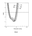
FIG.4 shows the frequency characteristics when the width of the short part of the bottom element is wider than the width of the short part of the upper element; -
FIG.5 shows the frequency characteristics when the width of a long part of the bottom element is wider than the width of a long part of the upper element; -
FIG.6 shows the frequency characteristics when the width of a long part of the upper element is wider than the width of a long part of the bottom element; -
FIG.7 shows an example of the frequency characteristics of the half-folded dipole antenna according toEmbodiment 1; -
FIG.8 shows the configuration ofEmbodiment 2; -
FIG.9 shows the radiation pattern of half-foldeddipole antenna 10A; -
FIG.10 shows the radiation pattern of half-foldeddipole antenna 10B; -
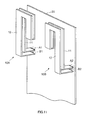
FIG.11 shows the configuration ofEmbodiment 3; and -
FIG.12 shows the frequency characteristics according toEmbodiment 3. - Now, embodiments of the present invention will be described in detail with reference to the accompanying drawings.
-
FIG.2 shows the schematic configuration of the half-folded dipole antenna according to the present embodiment. Half-foldeddipole antenna 10 inFIG.2 has the same configuration as the half-folded dipole antennas disclosed in above Non-PatentDocuments dipole antenna 10 of the present embodiment differs from the half-folded dipole antennas disclosed inNon-Patent Documents upper element 12 and the width ofbottom element 11 vary. InFIG.2 , to simplify the figure, the widths ofupper element 12 and the widths ofbottom element 11 are drawn such that they are the same width. - Half-folded
dipole antenna 10 is formed by the flat, J-shaped bottom element (first antenna element) 11 and upper element (second antenna element) 12 that overlap each other at interval b. -
Bottom element 11 is provided parallel to conductor plate20 aboveconductor plate 20. One end ofbottom element 11 is connected withconductor plate 20. With the present embodiment, a feed is provided at one end ofbottom element 11. -
Upper element 12 is folded back from the other end ofbottom element 11 throughfold part 13 to overlap withbottom element 11 in parallel at interval b. Further, one end ofupper element 12 is connected withplate conductor 20. With the present embodiment, one end ofupper element 12 is grounded. - To be more specific,
bottom element 11 andupper element 12 are formed byonset parts long parts middle parts short parts conductor plate 20. - Here, the shape joining
long part 11b,middle part 11c andshort part 11d ofbottom element 11, makes a J-shape. Similarly, the shape joininglong part 12b,middle part 12c andshort part 12d ofupper element 12, makes a J-shape. - The outside shape of half-folded
dipole antenna 10 is defined by seven parameters, w1, w2, wt, d, s, b and h shown in the figure. Here, parameter w1 represents the widths ofshort parts long parts middle parts middle parts long parts short parts bottom element 11 andupper element 12, and parameter h represents the height ofonset part 12a. - Incidentally, the above-described
Non-Patent Documents - With the present embodiment, amongst the above-described parameters w1, w2, wt, d, s, b and h as parameters to define the outside shape of half-folded
dipole antenna 10, it is proposed that w1, the width ofshort side parts long parts bottom element 11 andupper element 12. - That is, when the width of
short part 11d ofbottom element 11 is w1bottom and the width ofshort part 12d ofupper element 12 is w1upper,short parts bottom element 11 andupper element 12 are formed such that the relationship is w1bottom≠w1upper. Further, when the width oflong part 11b ofbottom element 11 is w2bottom and the width oflong part 12b ofupper element 12 is w2upper,long parts bottom element 11 andupper element 12 are formed such that the relationship is w2bottom≠w2upper. - By this means, it is possible to realize wider band or control frequency characteristics (to shift all frequency bands that can be used for reception to desired frequencies) without changing the total length of the antenna.
- Next, how to define a ratio between the width of
short part 11d ofbottom element 11 and width ofshort part 12d ofupper element 12 and how to define a ratio between the width oflong part 11b ofbottom element 11 and the width oflong part 12b ofupper element 12, will be explained in detail. Here, the following experimental results have been acquired. - <1> In the case where the width of
short part 12d ofupper element 12, w1upper, is wider than the width ofshort part 11d of bottom element, w1bottom. -
FIG.3 shows the frequency characteristics of half-foldeddipole antenna 10 when the width ofshort part 11d ofbottom element 11 , w1bottom=1 mm, the width oflong part 11b ofbottom element 11 , w2bottom= the width oflong part 12b ofupper element 12, w2upper =1 mm, the length ofmiddle part middle part onset part 12a, h=7 mm, the difference of length betweenlong part short part bottom element 11 andupper element 12, b =1 mm are fixed, and when the width ofshort part 12d ofupper element 12, w1upper, keeps widening in 1 mm units. -
FIG.3 shows the frequency characteristics of half-foldeddipole antenna 10 when curve S1 is w1upper=1 mm, curve S2 is w1upper=2 mm, curve S3 is w1upper=3 mm, curve S4 is w1upper=4 mm, and curve S5 is w1upper=5 mm. - It is evident from
FIG.3 that, when the width ofshort part 12d ofupper element 12, w1upper, is made wider than the width ofshort part 11d ofbottom element 11, w1bottom, it is possible to keep lowering the frequency almost without changing the frequency bandwidth. - <2> In the case where the width of
short part 11d ofbottom element 11, w1bottom, is wider than the width ofshort part 12d ofupper element 12, w1upper. -
FIG.4 shows the frequency characteristics of half-foldeddipole antenna 10 when the width ofshort part 12d ofupper element 12, w1upper=1 mm, the width oflong part 11b ofbottom element 11 , w2bottom= the width oflong part 12b ofupper element 12, w2upper =1 mm, d =5 mm, wt=1 mm, h=7 mm, s =12.5 mm, and b =1 mm are fixed, and when the width ofshort part 11d ofbottom element 11, w1bottom, keeps widening in 1 mm units. -
FIG.4 shows the frequency characteristics of half-foldeddipole antenna 10 when curve S1 is w1bottom=1 mm, curve S2 is w1 bottom=2 mm, curve S3 is w1bottom=3 mm, curve S4 is w1bottom=4 mm, and curve S5 is w1 bottom=5 mm. - It is evident from
FIG.4 that, when the width ofshort part 11d ofbottom element 11, w1bottom, is made wider than the width ofshort part 12d ofupper element 12, w1upper, it is possible to keep lowering the frequency almost without changing the frequency bandwidth. - <3> In the case where the width of
long part 11b ofbottom element 11, w2bottom, is wider than the width oflong part 12b ofupper element 12, w2upper. -
Fig. 5 shows the frequency characteristics of half-foldeddipole antenna 10 when the width oflong part 12b ofupper element 12, w2upper=1 mm, the width ofshort part 11d ofbottom element 11, w1bottom= the width ofshort part 12d ofupper element 12, w1upper =1 mm, d =5 mm, wt=1 mm, h=7 mm, s =12.5 mm, and b =1 mm are fixed, and when the width oflong part 11b ofbottom element 11, w2bottom, keeps widening in 1 mm units. -
Fig. 5 shows the frequency characteristics of half-foldeddipole antenna 10 when curve S1 is w2bottom=1 mm, curve S2 is w2bottom=2 mm, curve S3 is w2bottom=3 mm, curve S4is w2bottom=4 mm, and curve S5 is w2bottom=5 mm. - It is evident from
Fig. 5 that, when the width oflong part 11b ofbottom element 11, w2bottom, is made wider than the width oflong part 12b ofupper element 12, w2upper, it is possible to keep raising the frequency almost without changing in the frequency bandwidth. - <4> In the case where the width of
long part 12b ofupper element 12, w2upper, is wider than the width oflong part 11b ofbottom element 11, w2bottom. -
FIG.6 shows the frequency characteristics of half-foldeddipole antenna 10 when the width oflong part 11b ofbottom element 11, w2bottom=1 mm, the width ofshort part 11d ofbottom element 11, w1bottom= the width ofshort part 12d ofupper element 12, w1upper =1 mm, d=5 mm, wt=1 mm, h=7 mm, s =12.5 mm, and b=1 mm are fixed, and when the width oflong part 12b ofupper element 12, w2upper, keeps widening in 1 mm units. -
FIG.6 shows the frequency characteristics of half-foldeddipole antenna 10 when curve S1 is w2upper=1 mm, curve S2 is w2 upper=2 mm, curve S3 is w2 upper=3 mm, curve S4 is w2 upper=4 mm, and curve S5 is w2 upper=5 mm. - It is evident from
FIG.6 that, when the width oflong part 12b ofupper element 12, w2upper, is made wider than the width oflong part 11b ofbottom element 11, w2bottom, the frequency bandwidth is narrower, and therefore it is not adaptable to realize wide band. In this way, the reason the frequency bandwidth is narrower is that, in the present embodiment, the width ofupper element 12, in which a feed is not provided, is wider than the width ofbottom element 11, in which a feed is provided. - That is, it is evident from <3> and <4> that the element width of
long parts - Based on the above considerations, it has been found out that all frequencies can be lowered by making wider the element width of one of
short parts upper element 12 orbottom element 11 than the element width of the other. Further, it has been found out that all frequencies can be raised by making wider the element width oflong parts long parts upper element 12 orbottom element 11. - The half-folded dipole antenna according to the present embodiment makes wider the element width of one of
short parts upper element 12 orbottom element 11. By this means, half-foldeddipole antenna 10 of the configuration inFIG.2 can realize wide band further. -
FIG.7 shows the frequency characteristics of half-foldeddipole antenna 10 when the ratio between the width ofshort part 11d and the width ofshort part 12d is 1/5 (that is, the width ratio between w1upper=1 mm and w1bottom=5 mm), the ratio between the width oflong part 11b and the width oflong part 12b is 1/5 (that is, the width ratio between w1upper=1 mm and w1bottom=5 mm, d =5 mm, wt=1 mm, h=7 mm, s =12.5 mm, and b =1 mm. It is evident from the experimental result inFIG.7 that the configuration according to the present embodiment is able to achieve to realize wide band. - Half-folded
dipole antenna 10 according to the present embodiment can change frequencies without lengthening the antenna (that is, without changing "s" inFIG.2 ). Further, frequencies change and wide band can be realized by simply changing the ratio between the widths of upper element and bottom element, so that, it is possible to change frequencies and achieve to realize wide band without enlarging the element areas. -
FIG. 8 shows the configuration ofEmbodiment 2. The feature of the present embodiment includes placing two half-foldeddipole antennas FIG.2 along two upper end corners ofhousing 30 of a mobile phone device. To be more specific, two half-foldeddipole antennas long parts housing 30 and used in MIMO communication. - According to the present embodiment, it is possible to place the antennas efficiently in spaces at ends of the housing amongst various electronic parts in the housing, and, additionally, to reduce the correlation between antennas, so that it is possible to realize a portable terminal having good MIMO communication performance.. Further, wide band can be realized to achieve by applying the configuration in
Embodiment 1 to half-foldeddipole antennas -
FIG.9 andFIG.10 show the radiation pattern characteristics when antennas placed as inFig. 8 are adopted. Here, radiation pattern characteristics in center frequency 2.4 GHz have been investigated when the size ofhousing 30 is 45 mm×180 mm, the parameters of half-foldeddipole antennas -
FIG.9 shows a radiation pattern of half-foldeddipole antenna 10A andFIG.10 shows a radiation pattern of half-foldeddipole antenna 10B. For example, as known fromFIG.9B andFIG.10B , the radiation pattern in the X-Z plane is formed symmetrically toward the outside ofhousing 30. When the correlation coefficient betweenantennas - Further, when the current distribution at center frequency 2.4 GHz has been investigated, it has been found out that current is distributed around the antenna elements in a concentrated manner. By this means, even when a terminal used by holding it in a hand, the influence upon antenna characteristic is little. Normally, for a mobile phone device, which is usually used by holding it in a hand, less influence upon a human body suggests that safe communication is possible in any use conditions.
-
FIG. 11 shows an example of the configuration of half-folded dipole antenna according to the present embodiment. At half-foldeddipole antennas plate conductor 20, and resonant circuits A1 and A2 are loaded in these parts. - With the present embodiment, feeds B1 and B2 are grounded on
upper element 12, and parallel resonant circuits (LC circuits) A1 and A2 are connected withbottom element 1 1 . -
FIG.12 shows the frequency characteristics of half-foldeddipole antennas bottom element 11 is grounded directly) or where parallel resonant circuits are operated in OFF mode. - Meanwhile, the dotted lines show the frequency characteristics in the cases where parallel resonant circuits are provided and operated in ON mode. By providing parallel resonant circuits, it is possible to acquire the low frequency band between 1.6 and 1.9 GHz that cannot be acquired when parallel resonant circuits are not provided (the solid line in the figure), in addition to the frequency band between 2.2 and 2.6 GHz.
- By this means, multi frequency (multi resonance) can be achieved, so that it is possible to be adaptable to realize multi-band. Frequency bands can change to a certain extent by changing a circuit constant of a parallel resonant circuit.
- In this way, according to the present embodiment, by providing parallel resonant circuits A1 and A2 for half-folded
dipole antennas - The configurations of the above described
Embodiments 1 to 3 can be implemented by combining these embodiments. - Although cases have been explained with the
above Embodiments 1 to 3 where a half-folded dipole antenna having a J-shaped face as disclosed inNon-Patent Documents short side parts - That is, a half-folded dipole antenna having a L-shaped face, and, furthermore, other half-folded dipole antennas having other shaped faces can achieve to realize wide band and improve frequency characteristics as described the
above Embodiment 1 by making different the element widths of an upper element and bottom element. - Further, the half-folded dipole antenna having an L-shaped face in which
short side parts short side parts above Embodiment 2. - Further, a half-folded dipole antenna having an L-shaped face in which
short parts above Embodiment 3. - The half-folded dipole antenna of the present invention is suitable for use as an antenna built in a portable terminal that carries out MIMO communication. Further, the present invention is effective in technologies to communicate using a plurality of antennas besides MIMO communication, for example, AAA (Adaptive Array Antenna) communication.
Claims (7)
- A half-folded dipole antenna comprising:a first antenna element formed in a shape of a letter J, one end of the first antenna element being connected with a conductor plate; anda second antenna element formed in the shape of the letter J, having element widths that are different from the element widths of the first antenna element, and folded from the other end of the first antenna element to overlap with the first antenna element at a distance, one end of the second antenna element being connected with the conductor plate.
- The half-folded dipole antenna according to claim 1,
wherein, the first antenna element and second antenna element are each formed with a long part, a middle part and a short part,
wherein:the long part, the middle part and the short part are provided in ascending order of distance from where the first antenna element and second antenna element are connected with the conductor plate;the element width of the short part varies between the first antenna element and second antenna element; andthe element width of the long part of one of the first antenna element and second antenna element on a feed side, is wider than the element width of the long part of the other antenna element on a non-feed side. - A portable terminal comprising:a first half-folded dipole antenna and second half-folded dipole antenna that are placed along upper corners of a housing of the portable terminal,wherein the first half-folded dipole antenna and second half-folded dipole antenna each comprise:a first antenna element formed in a shape of a letter J, one end of the first antenna element being connected with a conductor plate; anda second antenna element formed in the shape of the letter J, folded from the other end of the first antenna element to overlap with the first antenna element at a distance, one end of the second antenna element being connected with the conductor plate.
- The portable terminal according to claim 3, wherein:the first antenna element and second antenna element of the first half-folded dipole antenna and second half-folded dipole antenna are each formed with a long part, a middle part and a short part,wherein the long part, the middle part and the short part are provided in ascending order of distance from where the first antenna element and second antenna element are connected with the plate conductor; and
the first half-folded dipole antenna and second half-folded dipole antenna are placed such that the long parts meet along each side of the housing. - The portable terminal according to claim 3, wherein the element widths vary between the first antenna element and second antenna element of the first half-folded dipole antenna and second half-folded dipole antenna.
- A half-folded dipole antenna comprising:a first antenna element formed in a shape of a letter J, one end of the first antenna element being connected with a conductor plate;a second antenna element formed in the shape of the letter J, folded from the other end of the first antenna element to overlap with the first antenna element at a distance, one end of the second antenna element being connected with the conductor plate;a power supplier connected with the end of the first antenna element; anda resonant circuit connected with the end of the second antenna element.
- The half-folded dipole antenna according to claim 6,
wherein the element widths vary between the first antenna element and second antenna element.
Applications Claiming Priority (1)
| Application Number | Priority Date | Filing Date | Title |
|---|---|---|---|
| PCT/JP2007/054299 WO2008107971A1 (en) | 2007-03-06 | 2007-03-06 | Folding dipole antenna |
Publications (3)
| Publication Number | Publication Date |
|---|---|
| EP2120292A1 true EP2120292A1 (en) | 2009-11-18 |
| EP2120292A4 EP2120292A4 (en) | 2010-03-03 |
| EP2120292B1 EP2120292B1 (en) | 2012-02-15 |
Family
ID=39737876
Family Applications (1)
| Application Number | Title | Priority Date | Filing Date |
|---|---|---|---|
| EP07737846A Not-in-force EP2120292B1 (en) | 2007-03-06 | 2007-03-06 | Folding dipole antenna |
Country Status (6)
| Country | Link |
|---|---|
| US (1) | US20100097285A1 (en) |
| EP (1) | EP2120292B1 (en) |
| JP (1) | JPWO2008107971A1 (en) |
| CN (1) | CN101627505A (en) |
| AT (1) | ATE545968T1 (en) |
| WO (1) | WO2008107971A1 (en) |
Cited By (5)
| Publication number | Priority date | Publication date | Assignee | Title |
|---|---|---|---|---|
| US10448173B2 (en) | 2017-10-16 | 2019-10-15 | Widex A/S | Antenna for a hearing assistance device |
| US10743119B2 (en) | 2017-10-16 | 2020-08-11 | Widex A/S | Antenna for a hearing assistance device |
| US10750295B2 (en) | 2017-10-16 | 2020-08-18 | Widex A/S | Antenna for a hearing assistance device |
| US10820123B2 (en) | 2017-10-16 | 2020-10-27 | Widex A/S | Antenna for a hearing assistance device |
| US11223109B2 (en) | 2017-10-16 | 2022-01-11 | Widex A/S | Antenna for a hearing assistance device |
Families Citing this family (9)
| Publication number | Priority date | Publication date | Assignee | Title |
|---|---|---|---|---|
| JP4952835B2 (en) * | 2009-11-20 | 2012-06-13 | 株式会社デンソー | Modified folded dipole antenna, impedance adjustment method thereof, and antenna device |
| JP5112530B2 (en) * | 2010-04-02 | 2013-01-09 | 原田工業株式会社 | Folded monopole antenna |
| EP2573873A1 (en) * | 2010-05-17 | 2013-03-27 | Panasonic Corporation | Antenna device and mobile wireless terminal with same mounted |
| GB2484542B (en) | 2010-10-15 | 2015-04-29 | Microsoft Technology Licensing Llc | LTE antenna pair for mimo/diversity operation in the LTE/GSM bands |
| CN104701608B (en) * | 2015-03-24 | 2018-09-04 | 上海与德通讯技术有限公司 | The wide frequency antenna of mobile terminal |
| US10305171B1 (en) * | 2017-04-24 | 2019-05-28 | Blue Digs LLC | Electronic devices with antenna arrays |
| US10992045B2 (en) * | 2018-10-23 | 2021-04-27 | Neptune Technology Group Inc. | Multi-band planar antenna |
| CA3057782C (en) * | 2018-10-23 | 2022-03-22 | Neptune Technology Group Inc. | Compact folded dipole antenna with multiple frequency bands |
| WO2025128957A1 (en) * | 2023-12-14 | 2025-06-19 | Battelle Memorial Institute | Reduced footprint antenna array system |
Family Cites Families (4)
| Publication number | Priority date | Publication date | Assignee | Title |
|---|---|---|---|---|
| US4413254A (en) * | 1981-09-04 | 1983-11-01 | Sensormatic Electronics Corporation | Combined radio and magnetic energy responsive surveillance marker and system |
| JP2003179426A (en) * | 2001-12-13 | 2003-06-27 | Matsushita Electric Ind Co Ltd | Antenna device and portable wireless device |
| JP2003209427A (en) * | 2002-01-09 | 2003-07-25 | Hidaka Denki Works Co Ltd | Miniaturized portable multi-frequency resonance antenna |
| JPWO2004047223A1 (en) * | 2002-11-18 | 2006-03-23 | 株式会社ヨコオ | Multi-band antenna |
-
2007
- 2007-03-06 WO PCT/JP2007/054299 patent/WO2008107971A1/en not_active Ceased
- 2007-03-06 US US12/529,075 patent/US20100097285A1/en not_active Abandoned
- 2007-03-06 AT AT07737846T patent/ATE545968T1/en active
- 2007-03-06 CN CN200780051978A patent/CN101627505A/en active Pending
- 2007-03-06 EP EP07737846A patent/EP2120292B1/en not_active Not-in-force
- 2007-03-06 JP JP2009502388A patent/JPWO2008107971A1/en not_active Withdrawn
Cited By (6)
| Publication number | Priority date | Publication date | Assignee | Title |
|---|---|---|---|---|
| US10448173B2 (en) | 2017-10-16 | 2019-10-15 | Widex A/S | Antenna for a hearing assistance device |
| US10674288B2 (en) | 2017-10-16 | 2020-06-02 | Widex A/S | Antenna for a hearing assistance device |
| US10743119B2 (en) | 2017-10-16 | 2020-08-11 | Widex A/S | Antenna for a hearing assistance device |
| US10750295B2 (en) | 2017-10-16 | 2020-08-18 | Widex A/S | Antenna for a hearing assistance device |
| US10820123B2 (en) | 2017-10-16 | 2020-10-27 | Widex A/S | Antenna for a hearing assistance device |
| US11223109B2 (en) | 2017-10-16 | 2022-01-11 | Widex A/S | Antenna for a hearing assistance device |
Also Published As
| Publication number | Publication date |
|---|---|
| US20100097285A1 (en) | 2010-04-22 |
| ATE545968T1 (en) | 2012-03-15 |
| JPWO2008107971A1 (en) | 2010-06-10 |
| EP2120292B1 (en) | 2012-02-15 |
| EP2120292A4 (en) | 2010-03-03 |
| CN101627505A (en) | 2010-01-13 |
| WO2008107971A1 (en) | 2008-09-12 |
Similar Documents
| Publication | Publication Date | Title |
|---|---|---|
| EP2120292B1 (en) | Folding dipole antenna | |
| KR102951856B1 (en) | Multilayer patch antenna | |
| US9379433B2 (en) | Multiple-input multiple-output (MIMO) antennas with multi-band wave traps | |
| US7307591B2 (en) | Multi-band antenna | |
| KR101217469B1 (en) | Multi-Input Multi-Output antenna with multi-band characteristic | |
| CN102150327B (en) | Antenna apparatus and wireless communication apparatus | |
| JP5163262B2 (en) | Antenna and communication apparatus having the antenna | |
| US20110260933A1 (en) | Mobile radio apparatus | |
| US20130057443A1 (en) | Antenna device, and wireless communication device | |
| US20050104783A1 (en) | Antenna for portable radio | |
| US20120306718A1 (en) | Antenna and wireless mobile terminal equipped with the same | |
| US20040032370A1 (en) | Portable radio-use antenna | |
| US8405555B2 (en) | Embedded UWB antenna and portable device having the same | |
| JPWO2011142135A1 (en) | Antenna device and portable wireless terminal equipped with the same | |
| CN112805877B (en) | Common Radiator Multi-Band Antenna System | |
| CN101194441A (en) | Antenna device | |
| KR20090031969A (en) | Antenna element and broadband antenna device | |
| US7391375B1 (en) | Multi-band antenna | |
| US20040095282A1 (en) | Antenna device | |
| EP2375488B1 (en) | Planar antenna and handheld device | |
| KR101218718B1 (en) | Diversity antenna device and mobile using the same | |
| JP4661816B2 (en) | Antenna and wireless communication device | |
| EP4456322A1 (en) | Antenna module and electronic device comprising same | |
| CN102683822A (en) | Antenna and terminal |
Legal Events
| Date | Code | Title | Description |
|---|---|---|---|
| PUAI | Public reference made under article 153(3) epc to a published international application that has entered the european phase |
Free format text: ORIGINAL CODE: 0009012 |
|
| 17P | Request for examination filed |
Effective date: 20090904 |
|
| AK | Designated contracting states |
Kind code of ref document: A1 Designated state(s): AT BE BG CH CY CZ DE DK EE ES FI FR GB GR HU IE IS IT LI LT LU LV MC MT NL PL PT RO SE SI SK TR |
|
| A4 | Supplementary search report drawn up and despatched |
Effective date: 20100202 |
|
| 17Q | First examination report despatched |
Effective date: 20100409 |
|
| DAX | Request for extension of the european patent (deleted) | ||
| REG | Reference to a national code |
Ref country code: DE Ref legal event code: R079 Ref document number: 602007020712 Country of ref document: DE Free format text: PREVIOUS MAIN CLASS: H01Q0009260000 Ipc: H01Q0021280000 |
|
| GRAP | Despatch of communication of intention to grant a patent |
Free format text: ORIGINAL CODE: EPIDOSNIGR1 |
|
| RIC1 | Information provided on ipc code assigned before grant |
Ipc: H01Q 21/28 20060101AFI20110715BHEP |
|
| GRAS | Grant fee paid |
Free format text: ORIGINAL CODE: EPIDOSNIGR3 |
|
| GRAA | (expected) grant |
Free format text: ORIGINAL CODE: 0009210 |
|
| AK | Designated contracting states |
Kind code of ref document: B1 Designated state(s): AT BE BG CH CY CZ DE DK EE ES FI FR GB GR HU IE IS IT LI LT LU LV MC MT NL PL PT RO SE SI SK TR |
|
| REG | Reference to a national code |
Ref country code: GB Ref legal event code: FG4D Ref country code: CH Ref legal event code: EP |
|
| REG | Reference to a national code |
Ref country code: IE Ref legal event code: FG4D |
|
| REG | Reference to a national code |
Ref country code: AT Ref legal event code: REF Ref document number: 545968 Country of ref document: AT Kind code of ref document: T Effective date: 20120315 |
|
| REG | Reference to a national code |
Ref country code: DE Ref legal event code: R096 Ref document number: 602007020712 Country of ref document: DE Effective date: 20120412 |
|
| PGFP | Annual fee paid to national office [announced via postgrant information from national office to epo] |
Ref country code: FR Payment date: 20120405 Year of fee payment: 6 |
|
| REG | Reference to a national code |
Ref country code: NL Ref legal event code: VDEP Effective date: 20120215 |
|
| PGFP | Annual fee paid to national office [announced via postgrant information from national office to epo] |
Ref country code: GB Payment date: 20120327 Year of fee payment: 6 |
|
| LTIE | Lt: invalidation of european patent or patent extension |
Effective date: 20120215 |
|
| PG25 | Lapsed in a contracting state [announced via postgrant information from national office to epo] |
Ref country code: LT Free format text: LAPSE BECAUSE OF FAILURE TO SUBMIT A TRANSLATION OF THE DESCRIPTION OR TO PAY THE FEE WITHIN THE PRESCRIBED TIME-LIMIT Effective date: 20120215 Ref country code: IS Free format text: LAPSE BECAUSE OF FAILURE TO SUBMIT A TRANSLATION OF THE DESCRIPTION OR TO PAY THE FEE WITHIN THE PRESCRIBED TIME-LIMIT Effective date: 20120615 Ref country code: NL Free format text: LAPSE BECAUSE OF FAILURE TO SUBMIT A TRANSLATION OF THE DESCRIPTION OR TO PAY THE FEE WITHIN THE PRESCRIBED TIME-LIMIT Effective date: 20120215 |
|
| PGFP | Annual fee paid to national office [announced via postgrant information from national office to epo] |
Ref country code: DE Payment date: 20120328 Year of fee payment: 6 |
|
| PG25 | Lapsed in a contracting state [announced via postgrant information from national office to epo] |
Ref country code: PT Free format text: LAPSE BECAUSE OF FAILURE TO SUBMIT A TRANSLATION OF THE DESCRIPTION OR TO PAY THE FEE WITHIN THE PRESCRIBED TIME-LIMIT Effective date: 20120615 Ref country code: GR Free format text: LAPSE BECAUSE OF FAILURE TO SUBMIT A TRANSLATION OF THE DESCRIPTION OR TO PAY THE FEE WITHIN THE PRESCRIBED TIME-LIMIT Effective date: 20120516 Ref country code: LV Free format text: LAPSE BECAUSE OF FAILURE TO SUBMIT A TRANSLATION OF THE DESCRIPTION OR TO PAY THE FEE WITHIN THE PRESCRIBED TIME-LIMIT Effective date: 20120215 Ref country code: FI Free format text: LAPSE BECAUSE OF FAILURE TO SUBMIT A TRANSLATION OF THE DESCRIPTION OR TO PAY THE FEE WITHIN THE PRESCRIBED TIME-LIMIT Effective date: 20120215 Ref country code: PL Free format text: LAPSE BECAUSE OF FAILURE TO SUBMIT A TRANSLATION OF THE DESCRIPTION OR TO PAY THE FEE WITHIN THE PRESCRIBED TIME-LIMIT Effective date: 20120215 Ref country code: BE Free format text: LAPSE BECAUSE OF FAILURE TO SUBMIT A TRANSLATION OF THE DESCRIPTION OR TO PAY THE FEE WITHIN THE PRESCRIBED TIME-LIMIT Effective date: 20120215 |
|
| REG | Reference to a national code |
Ref country code: AT Ref legal event code: MK05 Ref document number: 545968 Country of ref document: AT Kind code of ref document: T Effective date: 20120215 |
|
| PG25 | Lapsed in a contracting state [announced via postgrant information from national office to epo] |
Ref country code: CY Free format text: LAPSE BECAUSE OF FAILURE TO SUBMIT A TRANSLATION OF THE DESCRIPTION OR TO PAY THE FEE WITHIN THE PRESCRIBED TIME-LIMIT Effective date: 20120215 |
|
| PG25 | Lapsed in a contracting state [announced via postgrant information from national office to epo] |
Ref country code: SE Free format text: LAPSE BECAUSE OF FAILURE TO SUBMIT A TRANSLATION OF THE DESCRIPTION OR TO PAY THE FEE WITHIN THE PRESCRIBED TIME-LIMIT Effective date: 20120215 Ref country code: CZ Free format text: LAPSE BECAUSE OF FAILURE TO SUBMIT A TRANSLATION OF THE DESCRIPTION OR TO PAY THE FEE WITHIN THE PRESCRIBED TIME-LIMIT Effective date: 20120215 Ref country code: RO Free format text: LAPSE BECAUSE OF FAILURE TO SUBMIT A TRANSLATION OF THE DESCRIPTION OR TO PAY THE FEE WITHIN THE PRESCRIBED TIME-LIMIT Effective date: 20120215 Ref country code: EE Free format text: LAPSE BECAUSE OF FAILURE TO SUBMIT A TRANSLATION OF THE DESCRIPTION OR TO PAY THE FEE WITHIN THE PRESCRIBED TIME-LIMIT Effective date: 20120215 Ref country code: SI Free format text: LAPSE BECAUSE OF FAILURE TO SUBMIT A TRANSLATION OF THE DESCRIPTION OR TO PAY THE FEE WITHIN THE PRESCRIBED TIME-LIMIT Effective date: 20120215 Ref country code: DK Free format text: LAPSE BECAUSE OF FAILURE TO SUBMIT A TRANSLATION OF THE DESCRIPTION OR TO PAY THE FEE WITHIN THE PRESCRIBED TIME-LIMIT Effective date: 20120215 Ref country code: MC Free format text: LAPSE BECAUSE OF NON-PAYMENT OF DUE FEES Effective date: 20120331 |
|
| REG | Reference to a national code |
Ref country code: CH Ref legal event code: PL |
|
| PG25 | Lapsed in a contracting state [announced via postgrant information from national office to epo] |
Ref country code: SK Free format text: LAPSE BECAUSE OF FAILURE TO SUBMIT A TRANSLATION OF THE DESCRIPTION OR TO PAY THE FEE WITHIN THE PRESCRIBED TIME-LIMIT Effective date: 20120215 Ref country code: IT Free format text: LAPSE BECAUSE OF FAILURE TO SUBMIT A TRANSLATION OF THE DESCRIPTION OR TO PAY THE FEE WITHIN THE PRESCRIBED TIME-LIMIT Effective date: 20120215 |
|
| PLBE | No opposition filed within time limit |
Free format text: ORIGINAL CODE: 0009261 |
|
| STAA | Information on the status of an ep patent application or granted ep patent |
Free format text: STATUS: NO OPPOSITION FILED WITHIN TIME LIMIT |
|
| REG | Reference to a national code |
Ref country code: IE Ref legal event code: MM4A |
|
| 26N | No opposition filed |
Effective date: 20121116 |
|
| PG25 | Lapsed in a contracting state [announced via postgrant information from national office to epo] |
Ref country code: LI Free format text: LAPSE BECAUSE OF NON-PAYMENT OF DUE FEES Effective date: 20120331 Ref country code: IE Free format text: LAPSE BECAUSE OF NON-PAYMENT OF DUE FEES Effective date: 20120306 Ref country code: CH Free format text: LAPSE BECAUSE OF NON-PAYMENT OF DUE FEES Effective date: 20120331 Ref country code: AT Free format text: LAPSE BECAUSE OF FAILURE TO SUBMIT A TRANSLATION OF THE DESCRIPTION OR TO PAY THE FEE WITHIN THE PRESCRIBED TIME-LIMIT Effective date: 20120215 |
|
| REG | Reference to a national code |
Ref country code: DE Ref legal event code: R097 Ref document number: 602007020712 Country of ref document: DE Effective date: 20121116 |
|
| PG25 | Lapsed in a contracting state [announced via postgrant information from national office to epo] |
Ref country code: ES Free format text: LAPSE BECAUSE OF FAILURE TO SUBMIT A TRANSLATION OF THE DESCRIPTION OR TO PAY THE FEE WITHIN THE PRESCRIBED TIME-LIMIT Effective date: 20120526 |
|
| PG25 | Lapsed in a contracting state [announced via postgrant information from national office to epo] |
Ref country code: MT Free format text: LAPSE BECAUSE OF FAILURE TO SUBMIT A TRANSLATION OF THE DESCRIPTION OR TO PAY THE FEE WITHIN THE PRESCRIBED TIME-LIMIT Effective date: 20120215 Ref country code: BG Free format text: LAPSE BECAUSE OF FAILURE TO SUBMIT A TRANSLATION OF THE DESCRIPTION OR TO PAY THE FEE WITHIN THE PRESCRIBED TIME-LIMIT Effective date: 20120515 |
|
| GBPC | Gb: european patent ceased through non-payment of renewal fee |
Effective date: 20130306 |
|
| REG | Reference to a national code |
Ref country code: FR Ref legal event code: ST Effective date: 20131129 |
|
| REG | Reference to a national code |
Ref country code: DE Ref legal event code: R119 Ref document number: 602007020712 Country of ref document: DE Effective date: 20131001 |
|
| PG25 | Lapsed in a contracting state [announced via postgrant information from national office to epo] |
Ref country code: GB Free format text: LAPSE BECAUSE OF NON-PAYMENT OF DUE FEES Effective date: 20130306 Ref country code: FR Free format text: LAPSE BECAUSE OF NON-PAYMENT OF DUE FEES Effective date: 20130402 Ref country code: DE Free format text: LAPSE BECAUSE OF NON-PAYMENT OF DUE FEES Effective date: 20131001 |
|
| PG25 | Lapsed in a contracting state [announced via postgrant information from national office to epo] |
Ref country code: TR Free format text: LAPSE BECAUSE OF FAILURE TO SUBMIT A TRANSLATION OF THE DESCRIPTION OR TO PAY THE FEE WITHIN THE PRESCRIBED TIME-LIMIT Effective date: 20120215 |
|
| PG25 | Lapsed in a contracting state [announced via postgrant information from national office to epo] |
Ref country code: LU Free format text: LAPSE BECAUSE OF NON-PAYMENT OF DUE FEES Effective date: 20120306 |
|
| PG25 | Lapsed in a contracting state [announced via postgrant information from national office to epo] |
Ref country code: HU Free format text: LAPSE BECAUSE OF FAILURE TO SUBMIT A TRANSLATION OF THE DESCRIPTION OR TO PAY THE FEE WITHIN THE PRESCRIBED TIME-LIMIT Effective date: 20070306 |