EP2120090A1 - Wavelength converter - Google Patents
Wavelength converter Download PDFInfo
- Publication number
- EP2120090A1 EP2120090A1 EP08721984A EP08721984A EP2120090A1 EP 2120090 A1 EP2120090 A1 EP 2120090A1 EP 08721984 A EP08721984 A EP 08721984A EP 08721984 A EP08721984 A EP 08721984A EP 2120090 A1 EP2120090 A1 EP 2120090A1
- Authority
- EP
- European Patent Office
- Prior art keywords
- optical fiber
- zero
- wavelength
- light
- optical
- Prior art date
- Legal status (The legal status is an assumption and is not a legal conclusion. Google has not performed a legal analysis and makes no representation as to the accuracy of the status listed.)
- Withdrawn
Links
- 239000013307 optical fiber Substances 0.000 claims abstract description 138
- 239000006185 dispersion Substances 0.000 claims abstract description 107
- 230000003287 optical effect Effects 0.000 claims abstract description 47
- 239000000835 fiber Substances 0.000 claims description 10
- 238000001514 detection method Methods 0.000 claims description 7
- 238000006243 chemical reaction Methods 0.000 description 17
- 238000010586 diagram Methods 0.000 description 13
- 238000000034 method Methods 0.000 description 3
- 238000005516 engineering process Methods 0.000 description 2
- 238000010438 heat treatment Methods 0.000 description 1
- 230000010287 polarization Effects 0.000 description 1
- 238000001228 spectrum Methods 0.000 description 1
Images




Classifications
-
- G—PHYSICS
- G02—OPTICS
- G02F—OPTICAL DEVICES OR ARRANGEMENTS FOR THE CONTROL OF LIGHT BY MODIFICATION OF THE OPTICAL PROPERTIES OF THE MEDIA OF THE ELEMENTS INVOLVED THEREIN; NON-LINEAR OPTICS; FREQUENCY-CHANGING OF LIGHT; OPTICAL LOGIC ELEMENTS; OPTICAL ANALOGUE/DIGITAL CONVERTERS
- G02F1/00—Devices or arrangements for the control of the intensity, colour, phase, polarisation or direction of light arriving from an independent light source, e.g. switching, gating or modulating; Non-linear optics
- G02F1/35—Non-linear optics
- G02F1/353—Frequency conversion, i.e. wherein a light beam is generated with frequency components different from those of the incident light beams
-
- G—PHYSICS
- G02—OPTICS
- G02F—OPTICAL DEVICES OR ARRANGEMENTS FOR THE CONTROL OF LIGHT BY MODIFICATION OF THE OPTICAL PROPERTIES OF THE MEDIA OF THE ELEMENTS INVOLVED THEREIN; NON-LINEAR OPTICS; FREQUENCY-CHANGING OF LIGHT; OPTICAL LOGIC ELEMENTS; OPTICAL ANALOGUE/DIGITAL CONVERTERS
- G02F1/00—Devices or arrangements for the control of the intensity, colour, phase, polarisation or direction of light arriving from an independent light source, e.g. switching, gating or modulating; Non-linear optics
- G02F1/35—Non-linear optics
- G02F1/365—Non-linear optics in an optical waveguide structure
-
- G—PHYSICS
- G02—OPTICS
- G02F—OPTICAL DEVICES OR ARRANGEMENTS FOR THE CONTROL OF LIGHT BY MODIFICATION OF THE OPTICAL PROPERTIES OF THE MEDIA OF THE ELEMENTS INVOLVED THEREIN; NON-LINEAR OPTICS; FREQUENCY-CHANGING OF LIGHT; OPTICAL LOGIC ELEMENTS; OPTICAL ANALOGUE/DIGITAL CONVERTERS
- G02F1/00—Devices or arrangements for the control of the intensity, colour, phase, polarisation or direction of light arriving from an independent light source, e.g. switching, gating or modulating; Non-linear optics
- G02F1/35—Non-linear optics
- G02F1/353—Frequency conversion, i.e. wherein a light beam is generated with frequency components different from those of the incident light beams
- G02F1/3536—Four-wave interaction
-
- G—PHYSICS
- G02—OPTICS
- G02F—OPTICAL DEVICES OR ARRANGEMENTS FOR THE CONTROL OF LIGHT BY MODIFICATION OF THE OPTICAL PROPERTIES OF THE MEDIA OF THE ELEMENTS INVOLVED THEREIN; NON-LINEAR OPTICS; FREQUENCY-CHANGING OF LIGHT; OPTICAL LOGIC ELEMENTS; OPTICAL ANALOGUE/DIGITAL CONVERTERS
- G02F2201/00—Constructional arrangements not provided for in groups G02F1/00 - G02F7/00
- G02F2201/02—Constructional arrangements not provided for in groups G02F1/00 - G02F7/00 fibre
Definitions
- the present invention relates to a wavelength converter that generates converted light having a wavelength different from that of input light.
- Non-patent Document I M. Onishi, et al.: Proc. 23rd ECOC, 1997, vol. 2, p.115 ) discloses that a desired wavelength conversion characteristic can be obtained by adjusting the wavelength of pump light, which is input to an optical fiber, in accordance with the zero-dispersion wavelength of the optical fiber.
- Non-patent Document 2 K. Inoue, et al.: IEEE Photonics Technology Lett., vol. 6 (1994) 1451 ) discloses a wavelength-tunable light source that can be used for such a purpose.
- a wavelength converter using the wavelength-tunable light source has a complex structure and is expensive.
- Non-patent Document 3 (M. Takahashi et al.: Proc. 32nd ECOC 2006 Th.1.5.1) discloses a method for shifting the zero-dispersion wavelength of a highly nonlinear fiber by stretching the fiber.
- Non-patent Document 3 does not disclose a specific method for applying tension to the fiber. In particular, a method for repeatedly changing tension is not examined in Non-patent Document 3.
- An object of the invention is to provide a wavelength converter having a simple and lovcr-cost structure.
- a wavelength converter that generates converted light having a wavelength different from that of input light.
- the wavelength converter includes (1) a pump light source that outputs pump light, (2) an optical multiplexer that combines and outputs input light and the pump light, (3) a first optical fiber that receives and guides the input light and the pump light that have been combined and output by the optical multiplexer and generates converted light using a nonlinear optical phenomenon that occurs while the first optical fiber guides the input light and the pump light, the first optical fiber being coiled, and (4) zero-dispersion wavelength adjusting means that adjusts a zero-dispersion wavelength of the first optical fiber.
- the first optical fiber be a highly nonlinear fiber (an optical fiber with a nonlinear coefficient ⁇ equal to or greater than 10 W -1 km -1 ).
- the zero-dispersion wavelength adjusting means can adjust the zero-dispersion wavelength of the first optical fiber by adjusting the temperature, the stress, or the tension of the first optical fiber.
- a temperature adjustment range be equal to or greater than 40°C.
- the zero-dispersion wavelength adjusting means changes the inside diameter of the first optical fiber being coiled.
- the wavelength converter according to the invention further includes (a) a detector that detects a state of the first optical fiber, (b) a controller that controls an adjustment of the zero-dispersion wavelength of the first optical fiber by the zero-dispersion wavelength adjusting means on the basis of a result of the detection by the detector.
- the zero-dispersion wavelength adjusting means be configured such that portions to which the temperature, tension, or stress is applied can be separately controlled.
- the zero-dispersion wavelength adjusting means can adjust the zero-dispersion wavelength of an optical fiber such that the zero-dispersion wavelength is substantially constant across a coil of the optical fiber.
- an optical fiber which is to be coiled, can be prepared such that the outer diameter, the core diameter, and the residual stress characteristic are changed along the length.
- the wavelength converter according to the invention may include a plurality of fibers having different characteristics and each being coiled or a plurality of fibers having the same characteristic and each being coiled.
- the zero-dispersion wavelength adjusting means simultaneously or independently adjusts the temperatures, the stresses, or the tensions of the optical fibers so as to adjust the zero-dispersion wavelengths of the optical fibers.
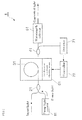
- Fig. 1 is a conceptual diagram of a wavelength converter according to a first embodiment of the invention.
- Fig. 2 is a graph showing chromatic dispersion characteristics of an optical fiber included in the wavelength converter according to the first embodiment.
- Fig. 3 is a graph showing wavelength conversion efficiency characteristics of the wavelength converter according to the first embodiment.
- Fig. 4 is a conceptual diagram showing an exemplifying structure of zero-dispersion wavelength adjusting means included in the wavelength converter according to the first embodiment.
- Fig. 5 is a conceptual diagram showing another exemplifying structure of the zero-dispersion wavelength adjusting means included in the wavelength converter according to the first embodiment.
- Fig. 6 is a conceptual diagram showing still another exemplifying structure of the zero-dispersion wavelength adjusting means included in the wavelength converter according to the first embodiment.
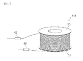
- Fig. 7 is a conceptual diagram showing still another exemplifying structure of the zero-dispersion wavelength adjusting means included in the wavelength converter according to the first embodiment.
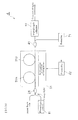
- Fig. 8 is a conceptual diagram of a wavelength converter according to a second embodiment of the invention.
- Fig. 9 is a conceptual diagram of a wavelength converter according to a third embodiment of the invention.
- Fig. 10 is a conceptual diagram of a wavelength converter according to a fourth embodiment of the invention.
- Fig. 1 is a conceptual diagram of a wavelength converter 1 according to a first embodiment of the invention.
- a pump light source 11 outputs pump light.
- An optical multiplexer 21 receives input light to be converted and the pump light that has been output from the pump light source 11, and the optical multiplexer 21 combines and outputs the input light and the pump light.
- An optical fiber 31 receives the input light and the pump light that have been combined and output from the optical multiplexer 21 at one end thereof, and guides the input light and the pump light.
- the optical fiber 31 generates converted light using a nonlinear optical phenomenon (four-wave mixing) that occurs while the optical fiber 31 guides the input light and the pump light, and outputs the converted light from the other end thereof.
- the optical fiber 31 has a zero-dispersion wavelength in the vicinity of the pump light wavelength.
- the light output from the other end of the optical fiber 31 includes not only the converted light but also the pump light and light having the same wavelength as that of the input light.
- the optical fiber 31 be a highly nonlinear fiber (an optical fiber with a nonlinear coefficient ⁇ equal to or greater than 10 W -1 km -1 ).
- highly nonlinear fibers are disclosed in Non-patent Document 4 ( T. Okuno, et al.: IEEE J. Select. Topics in Quantum Electron. Vol. 5 (1999) 1385 ) and Non-patent Document 5 ( T. Okuno, et al.: Electron. Lett. vol. 39 (2003) 972 ).
- the wavelength converter 1 has a high wavelength conversion efficiency, so that the length of the optical fiber 31. can be shortened.
- the optical fiber 31 be coiled.
- the wavelength converter can be made small and easy-to-handle.
- An optical demultiplexer 41 outputs almost all the light that has been output from the optical fiber 31 to a wavelength selector 51 while splitting a part of the light and outputs the part to a detector 71.
- the wavelength selector 51 receives light that has been output from the optical demultiplexer 41 and has reached the wavelength selector 51, and selectively outputs converted light among the received light.
- the wavelength selector 51 is, for example, an optical filter, an optical separator, or the like.
- a zero-dispersion wavelength adjusting means 61 adjusts the zero-dispersion wavelength of the optical fiber 31.
- the zero-dispersion wavelength adjusting means 61 adjusts the zero-dispersion wavelength of the optical fiber 31 by adjusting the temperature, the stress, or the tension of the optical fiber 31.
- the temperature adjustment range be equal to or greater than 40°C. In this case, the adjustment amount of the zero-dispersion wavelength of the optical fiber 31 can be made sufficiently large, so that the adjustment amount of the wavelength conversion characteristic of the wavelength converter 1 can be made sufficiently large.
- the detector 71 receives light that has been split by the optical demultiplexer 41 and has reached the detector 71, and detects a state of the optical fiber 31 on the basis of the result of receiving the light. At this time, the detector 71 detects the state of the optical fiber 31 on the basis of the power of received light, the spectrum of the received light, or the power of the converted light among the received light. On the basis of the result of the detection by the detector 71, the controller 72 controls the adjustment of the zero-dispersion wavelength of the optical fiber 31 by the zero-dispersion wavelength adjusting means 61.
- the wavelength converter 1 operates as follows. Input light to be converted and pump light that has been output from the pump light source 11 are combined by the optical multiplexer 21 and input to one end of the optical fiber 31. While the input light and the pump light are being guided along the optical fiber 31, a nonlinear optical phenomenon occurs, so that converted light having a wavelength different from that of the input light is generated in the optical fiber 31. The converted light generated in the optical fiber 31 is output from the other end of the optical fiber 31, and the converted light passes through the optical demultiplexer 41 and the wavelength selector 51 so as to be output.
- the zero-dispersion wavelength adjusting means 61 adjusts the zero-dispersion wavelength of the optical fiber 31, so that the wavelength conversion characteristic of the wavelength converter 1 can be adjusted.
- the detector 71 detects the state of the optical fiber 31.
- the controller 72 controls the adjustment of the zero-dispersion wavelength of the optical fiber 31 by the zero-dispersion wavelength adjusting means 61.
- the phase matching of four-wave mixing shifts to a longer wavelength when an input power is high.
- controlling the zero-dispersion wavelength in accordance with the input power may be necessary in some cases.
- the invention enables flexible operation by, for example, controlling or maintaining the conversion bandwidth without changing the wavelength in accordance with the increase/decrease of the input power.
- the pump light wavelength is 1549.4 nm and the optical fiber 31 is a highly nonlinear fiber having characteristics shown in Table at the pump light wavelength and having a length of 1 km.
- the differential coefficient (d ⁇ 0 /dT) of the zero-dispersion wavelength ⁇ 0 is 0.02 nm/°C at room temperature.
- the wavelength dependence of the dispersion slope and the zero-dispersion wavelength of the optical fiber 31 are uniform along the length.
- Fig. 2 is a graph showing chromatic dispersion characteristics of the optical fiber 31.
- the solid line shows the chromatic dispersion characteristic (case 1) at temperature T 0
- the broken line shows the chromatic dispersion characteristic (case 2) at temperature (T 0 + 40°C).
- the zero-dispersion wavelength is 1549.8 nm.
- the zero-dispersion wavelength is 1550.6 nm.
- Fig. 3 is a graph showing wavelength conversion efficiency characteristics of the wavelength converter 1.
- the abscissa represents the difference ⁇ between the wavelengths of input light and pump light.
- the ordinate represents the wavelength conversion efficiency ⁇ that is normalized by the wavelength conversion efficiency when the wavelengths of input light and pump light are the same.
- the wavelength conversion bandwidth (full width at half maximum) is 49.2 nm for case 1 and 23.6 nm for case 2.
- Figs. 4 to 7 are conceptual diagrams showing exemplifying structures 611 to 614 of the zero-dispersion wavelength adjusting means 61.
- the optical fiber 31 is coiled around the body of a bobbin 33.
- Zero-dispersion wavelength adjusting means 611 shown in Fig. 4 includes a voltage supply 62.
- the voltage supply 62 adjusts the zero-dispersion wavelength of the optical fiber 31 by applying a voltage to the bobbin 33 so that an electric current passes through the bobbin 33 and thereby heating the optical fiber 31.
- the zero-dispersion wavelength adjusting means 611 may include a heater or a Pertier device provided to the bobbin 33 or the optical fiber 31 so as to heat the optical fiber 31 and thereby adjust the zero-dispersion wavelength of the optical fiber 31.
- Zero-dispersion wavelength adjusting means 612 shown in Fig. 5 includes a voltage supply 63.
- the voltage supply 63 adjusts the zero-dispersion wavelength of the optical fiber 31 by applying a voltage to a body 32 of the bobbin 33 so that an electric current passes through the body 32 and thereby thermally expanding the body 32 and changing the stress of the optical fiber 31.
- Zero-dispersion wavelength adjusting means 613 shown in Fig. 6 includes an expandable and contractible member 64.
- the expandable and contractible member 64 is a cylinder-shaped member that is inserted into the body of the bobbin 33.
- the expandable and contractible member can expand and contract in radial directions by using a piezoelectric device or the like.
- the expandable and contractible member 64 adjusts the zero-dispersion wavelength of the optical fiber 31 by expanding and contracting in radial directions so that the stress of the optical fiber 31 is changed.
- the body of the bobbin itself may be the piezoelectric device.
- Zero-dispersion wavelength adjusting means 614 shown in Fig. 7 includes tension-applying units 65.
- the tension-applying units 65 which are movable while holding the ends of the optical fiber 31, adjust the zero-dispersion wavelength of the optical fiber 31 by applying tension to the optical fiber 31.
- the bobbin 33 may rotate so that tension is applied to the optical fiber 31 and the zero-dispersion wavelength of the optical fiber 31 is adjusted.
- Fig. 8 is a conceptual diagram of a wavelength converter 2 according to a second embodiment of the invention.
- Each of optical fibers 31A and 31B is similar to the optical fiber 31 in the first embodiment.
- the optical fibers 31A and 31B may be of the same kind or of different kinds.
- Each of zero-dispersion wavelength adjusting means 61A and 61B is similar to the zero-dispersion wavelength adjusting means 61 in the first embodiment.
- the zero-dispersion wavelength adjusting means 61A adjusts the zero-dispersion wavelength of the optical fiber 31A.
- the zero-dispersion wavelength adjusting means 61B adjusts the zero-dispersion wavelength of the optical fiber 31B.
- the wavelength converter 2 operates as follows. Input light to be convened and pump light that has been output from a pump light source 11 are combined by an optical multiplexer 21 and input to one end of the optical fiber 31A. While the input light and the pump light, which have been input to one end of the optical fiber 31A, are guided along the optical fibers 31A and 31B, a nonlinear optical phenomenon occurs, so that converted light having a wavelength different from that of the input light is generated in the optical fibers 31 A and 31B. The converted light generated in the optical fibers 31A and 31B is output from the other end of the optical fiber 31B, and the converted light passes through the optical demultiplexer 41 and the wavelength selector 51 so as to be output.
- the zero-dispersion wavelength adjusting means 61 A adjusts the zero-dispersion wavelength of the optical fiber 31A and the zero-dispersion wavelength adjusting means 61B adjusts the zero-dispersion wavelength of the optical fiber 31B, so that the wavelength conversion characteristic of the wavelength converter 2 can be adjusted.
- the detector 71 detects the states of the optical fibers 31A and 31B.
- the controller 72 controls the adjustment of the zero-dispersion wavelengths of the optical fibers 31A and 31B by the zero-dispersion wavelength adjusting means 61A and 61B.
- Fig. 9 is a conceptual diagram of a wavelength converter 3 according to a third embodiment of the invention.
- the wavelength converter 3 further includes an optical demultiplexer 12 and an optical multiplexer 22.
- the optical demultiplexer 12 bifurcates pump light that has been output from a pump light source 11, and outputs the bifurcated pump light to the optical multiplexers 21 and 22.
- Input light to be converted and the pump light that has reached from the optical demultiplexer 12 are input to the optical multiplexer 21.
- the optical multiplexer 21 combines and outputs the input light and the pump light to an optical fiber 31A.
- Light that has been output from the optical fiber 31A and the pump light that has reached from the optical demultiplexer 12 are input to the optical multiplexer 22.
- the optical multiplexer 22 combines and outputs these light to an optical fiber 31B.
- the wavelength converter 3 operates as follows. Input light to be converted and one part of pump light that has been output form the pump light source 11 and bifurcated by the optical demultiplexer 12 are combined by the optical multiplexer 21 and input to one end of the optical fiber 31A. Light output from the other end of the optical fiber 31A and the other part of pump light that has been output from the pump light source 11 and bifurcated by the optical demultiplexer 12 are combined by the optical multiplexer 22 and input to one end of the optical fiber 31B. While the input light and the pump light are guided along the optical fibers 31A and 31B, a nonlinear optical phenomenon occurs, so that converted light having a wavelength different from that of the input light is generated in the optical fibers 31A and 31B. The converted light that has been generated in the optical fibers 31A and 31B is output from the other end of the optical fiber 31B, and the converted light passes through an optical demultiplexer 41 and a wavelength selector 51 so as to be output.
- the zero-dispersion wavelength adjusting means 61A adjusts the zero-dispersion wavelength of the optical fiber 31A and the zero-dispersion wavelength adjusting means 61B adjusts the zero-dispersion wavelength of the optical fiber 31B, so that the wavelength conversion characteristic of the wavelength converter 3 can be adjusted.
- a detector 71 detects the states of the optical fibers 31A and 31B.
- a controller 72 adjusts the adjustment of the zero-dispersion wavelength of the optical fibers 31A and 31B by the zero-dispersion wavelength adjusting means 61A and 61B.
- the wavelength converter 3 has a simple and low-cost structure.
- the branching ratio of the demultiplexer 12 or the powers of branched outputs be variable. In this case, the conversion efficiencies of the optical fibers 31 A and 31B can be independently adjusted. It is preferable that the demultiplexer 12 be also controlled by the controller 72.
- Fig. 10 is a conceptual diagram of a wavelength converter 4 according to a fourth embodiment of the invention.
- the wavelength converter 4 is different in that common zero-dispersion wavelength adjusting means 61 adjusts the zero-dispersion wavelength of each of two optical fibers 31 A and 31B.
- the wavelength converter 4 operates as follows. Input light to be converted and pump light that has been output from a pump light source 11 are combined by an optical multiplexer 21 and input to one end of an optical fiber 31A. While the input light and pump light that have been input to one end of the optical fiber 31A are guided along the optical fibers 31A and 31B, a nonlinear optical phenomenon occurs, so that converted light having a wavelength different from that of the input light is generated in the optical fibers 31A and 31B. The converted light generated in the optical fibers 31A and 31B is output from the other end of the optical fiber 31B, and the conversed light passes through an optical demultiplexer 41 and a wavelength selector 51 so as to be output.
- the zero-dispersion wavelength adjusting means 61 adjusts the zero-dispersion wavelengths of the optical fibers 31A and 31B, so that the wavelength conversion characteristic of the wavelength converter 4 can be adjusted.
- a detector 71 detects the states of the optical fibers 31A and 31B.
- a controller 72 controls the adjustment of the zero-dispersion wavelengths of the optical fibers 31A and 31B by the zero-dispersion wavelength adjusting means 61.
- the wavelength converter 4 has a simple and low-cost structure. If the dispersion slopes of the optical fibers 31A and 31B are the same, the difference between the zero-dispersion wavelengths of the optical fibers 31A and 31B is constant even when the temperature is changed.
- a wavelength converter having a simple and low-cost structure is provided.
- the wavelength converter is suitable for an optical communications system.
Landscapes
- Physics & Mathematics (AREA)
- Nonlinear Science (AREA)
- General Physics & Mathematics (AREA)
- Optics & Photonics (AREA)
- Optical Modulation, Optical Deflection, Nonlinear Optics, Optical Demodulation, Optical Logic Elements (AREA)
- Optical Fibers, Optical Fiber Cores, And Optical Fiber Bundles (AREA)
Abstract
Provided is a wavelength converter having a simple and low-cost structure. The wavelength converter generates converted light having a wavelength different from that of input light. The wavelength converter includes (1) a pump light source that outputs pump light, (2) an optical multiplexer that combines and outputs input light and the pump light, (3) a first optical fiber that receives and guides the input light and the pump light that have been combined and output by the optical multiplexer and generates converted light using a nonlinear optical phenomenon that occurs while the first optical fiber guides the input light and the pump light, the first optical fiber being coiled, and (4) zero-dispersion wavelength adjusting means that adjusts a zero-dispersion wavelength of the first optical fiber.
Description
- The present invention relates to a wavelength converter that generates converted light having a wavelength different from that of input light.
- Some wavelength converters generate converted light having a wavelength different from that of input light by using a nonlinear optical phenomenon, such as four-wave mixing, that occurs in an optical fiber. Non-patent Document I (M. Onishi, et al.: Proc. 23rd ECOC, 1997, vol. 2, p.115) discloses that a desired wavelength conversion characteristic can be obtained by adjusting the wavelength of pump light, which is input to an optical fiber, in accordance with the zero-dispersion wavelength of the optical fiber. Non-patent Document 2 (K. Inoue, et al.: IEEE Photonics Technology Lett., vol. 6 (1994) 1451) discloses a wavelength-tunable light source that can be used for such a purpose. A wavelength converter using the wavelength-tunable light source has a complex structure and is expensive.
- On the other hand, attempts have been made to obtain a desired wavelength conversion characteristic by adjusting the zero-dispersion wavelength of an optical fiber. For example, Non-patent Document 3 (M. Takahashi et al.: Proc. 32nd ECOC 2006 Th.1.5.1) discloses a method for shifting the zero-dispersion wavelength of a highly nonlinear fiber by stretching the fiber. However, Non-patent Document 3 does not disclose a specific method for applying tension to the fiber. In particular, a method for repeatedly changing tension is not examined in Non-patent Document 3.
- Non-patent Document 1: M. Onishi, et al.: Proc. 23rd ECOC, 1997, vol. 2, p.115.
- Non-patent Document 2: K. Inoue, et al.: IEEE Photonics Technology Lett., vol. 6 (1994) 1451.
- Non-patent Document 3 : M. Takahashi et aL: Proc. 32nd ECOC 2006 Th.1.5.1.
- Non-patent Document 4: T. Okuno, et al.: IEEE J. Select. Topics in Quantum Electron. Vol. 5 (1999) 1385.
- Non-patent Document 5: T. Okuno, et al.: Electron. Lett. vol. 39 (2003) 972.
- An object of the invention is to provide a wavelength converter having a simple and lovcr-cost structure.
- To achieve the object, a wavelength converter that generates converted light having a wavelength different from that of input light is provided. The wavelength converter includes (1) a pump light source that outputs pump light, (2) an optical multiplexer that combines and outputs input light and the pump light, (3) a first optical fiber that receives and guides the input light and the pump light that have been combined and output by the optical multiplexer and generates converted light using a nonlinear optical phenomenon that occurs while the first optical fiber guides the input light and the pump light, the first optical fiber being coiled, and (4) zero-dispersion wavelength adjusting means that adjusts a zero-dispersion wavelength of the first optical fiber.
- In the wavelength converter according to the invention, it is preferable that the first optical fiber be a highly nonlinear fiber (an optical fiber with a nonlinear coefficient γ equal to or greater than 10 W-1km-1). The zero-dispersion wavelength adjusting means can adjust the zero-dispersion wavelength of the first optical fiber by adjusting the temperature, the stress, or the tension of the first optical fiber. When the zero-dispersion wavelength is adjusted by adjusting the temperature, it is preferable that a temperature adjustment range be equal to or greater than 40°C. When the zero-dispersion wavelength is adjusted by adjusting the stress, the zero-dispersion wavelength adjusting means changes the inside diameter of the first optical fiber being coiled. It is preferable that the wavelength converter according to the invention further includes (a) a detector that detects a state of the first optical fiber, (b) a controller that controls an adjustment of the zero-dispersion wavelength of the first optical fiber by the zero-dispersion wavelength adjusting means on the basis of a result of the detection by the detector.
- It is preferable that the zero-dispersion wavelength adjusting means be configured such that portions to which the temperature, tension, or stress is applied can be separately controlled. With this configuration, the zero-dispersion wavelength adjusting means can adjust the zero-dispersion wavelength of an optical fiber such that the zero-dispersion wavelength is substantially constant across a coil of the optical fiber. Without separate control, the same result can be achieved with a simple structure by providing a control system with a pre-designed condition that makes the zero-dispersion wavelength be constant along the length with respect to each zero-dispersion wavelength. Moreover, an optical fiber, which is to be coiled, can be prepared such that the outer diameter, the core diameter, and the residual stress characteristic are changed along the length. By using such an optical fiber, a substantially constant zero-dispersion wavelength can be provided across the coil even with a simple zero-dispersion wavelength adjusting means having, for example, one control point.
- In addition, the wavelength converter according to the invention may include a plurality of fibers having different characteristics and each being coiled or a plurality of fibers having the same characteristic and each being coiled. In this case, the zero-dispersion wavelength adjusting means simultaneously or independently adjusts the temperatures, the stresses, or the tensions of the optical fibers so as to adjust the zero-dispersion wavelengths of the optical fibers.
-
Fig. 1 is a conceptual diagram of a wavelength converter according to a first embodiment of the invention. -
Fig. 2 is a graph showing chromatic dispersion characteristics of an optical fiber included in the wavelength converter according to the first embodiment. -
Fig. 3 is a graph showing wavelength conversion efficiency characteristics of the wavelength converter according to the first embodiment. -
Fig. 4 is a conceptual diagram showing an exemplifying structure of zero-dispersion wavelength adjusting means included in the wavelength converter according to the first embodiment. -
Fig. 5 is a conceptual diagram showing another exemplifying structure of the zero-dispersion wavelength adjusting means included in the wavelength converter according to the first embodiment. -
Fig. 6 is a conceptual diagram showing still another exemplifying structure of the zero-dispersion wavelength adjusting means included in the wavelength converter according to the first embodiment. -
Fig. 7 is a conceptual diagram showing still another exemplifying structure of the zero-dispersion wavelength adjusting means included in the wavelength converter according to the first embodiment. -
Fig. 8 is a conceptual diagram of a wavelength converter according to a second embodiment of the invention. -
Fig. 9 is a conceptual diagram of a wavelength converter according to a third embodiment of the invention. -
Fig. 10 is a conceptual diagram of a wavelength converter according to a fourth embodiment of the invention. - Hereinafter, embodiments of the invention are described with reference to the drawings. The drawings are for illustrative purposes only, and do not limit the scope of the invention. In the drawings, the same numerals denote the same elements so as to avoid redundant description. Ratios of dimensions in the drawings are not necessarily accurate.
-
Fig. 1 is a conceptual diagram of awavelength converter 1 according to a first embodiment of the invention. In thewavelength converter 1, apump light source 11 outputs pump light. Anoptical multiplexer 21 receives input light to be converted and the pump light that has been output from thepump light source 11, and theoptical multiplexer 21 combines and outputs the input light and the pump light. Anoptical fiber 31 receives the input light and the pump light that have been combined and output from theoptical multiplexer 21 at one end thereof, and guides the input light and the pump light. Theoptical fiber 31 generates converted light using a nonlinear optical phenomenon (four-wave mixing) that occurs while theoptical fiber 31 guides the input light and the pump light, and outputs the converted light from the other end thereof. Theoptical fiber 31 has a zero-dispersion wavelength in the vicinity of the pump light wavelength. The light output from the other end of theoptical fiber 31 includes not only the converted light but also the pump light and light having the same wavelength as that of the input light. - It is preferable that the
optical fiber 31 be a highly nonlinear fiber (an optical fiber with a nonlinear coefficient γ equal to or greater than 10 W-1km-1). Examples of highly nonlinear fibers are disclosed in Non-patent Document 4 (T. Okuno, et al.: IEEE J. Select. Topics in Quantum Electron. Vol. 5 (1999) 1385) and Non-patent Document 5 (T. Okuno, et al.: Electron. Lett. vol. 39 (2003) 972). In this case, thewavelength converter 1 has a high wavelength conversion efficiency, so that the length of theoptical fiber 31. can be shortened. Therefore, polarization mode dispersion, stimulated Brillouin scattering, and variation of dispersion characteristics along the length can be reduced. It is preferable that theoptical fiber 31 be coiled. In this case, the wavelength converter can be made small and easy-to-handle. - An
optical demultiplexer 41 outputs almost all the light that has been output from theoptical fiber 31 to awavelength selector 51 while splitting a part of the light and outputs the part to adetector 71. Thewavelength selector 51 receives light that has been output from theoptical demultiplexer 41 and has reached thewavelength selector 51, and selectively outputs converted light among the received light. Thewavelength selector 51 is, for example, an optical filter, an optical separator, or the like. - A zero-dispersion wavelength adjusting means 61 adjusts the zero-dispersion wavelength of the
optical fiber 31. The zero-dispersion wavelength adjusting means 61 adjusts the zero-dispersion wavelength of theoptical fiber 31 by adjusting the temperature, the stress, or the tension of theoptical fiber 31. When the zero-dispersion wavelength adjusting means 61 adjusts the temperature of theoptical fiber 31, it is preferable that the temperature adjustment range be equal to or greater than 40°C. In this case, the adjustment amount of the zero-dispersion wavelength of theoptical fiber 31 can be made sufficiently large, so that the adjustment amount of the wavelength conversion characteristic of thewavelength converter 1 can be made sufficiently large. - The
detector 71 receives light that has been split by theoptical demultiplexer 41 and has reached thedetector 71, and detects a state of theoptical fiber 31 on the basis of the result of receiving the light. At this time, thedetector 71 detects the state of theoptical fiber 31 on the basis of the power of received light, the spectrum of the received light, or the power of the converted light among the received light. On the basis of the result of the detection by thedetector 71, thecontroller 72 controls the adjustment of the zero-dispersion wavelength of theoptical fiber 31 by the zero-dispersion wavelength adjusting means 61. - The
wavelength converter 1 operates as follows. Input light to be converted and pump light that has been output from thepump light source 11 are combined by theoptical multiplexer 21 and input to one end of theoptical fiber 31. While the input light and the pump light are being guided along theoptical fiber 31, a nonlinear optical phenomenon occurs, so that converted light having a wavelength different from that of the input light is generated in theoptical fiber 31. The converted light generated in theoptical fiber 31 is output from the other end of theoptical fiber 31, and the converted light passes through theoptical demultiplexer 41 and thewavelength selector 51 so as to be output. - At this time, the zero-dispersion wavelength adjusting means 61 adjusts the zero-dispersion wavelength of the
optical fiber 31, so that the wavelength conversion characteristic of thewavelength converter 1 can be adjusted. Moreover, thedetector 71 detects the state of theoptical fiber 31. On the basis of the result of the detection by thedetector 71, thecontroller 72 controls the adjustment of the zero-dispersion wavelength of theoptical fiber 31 by the zero-dispersion wavelength adjusting means 61. With this configuration, the wavelength conversion characteristic can not only be adjusted but stably maintained to be a desired characteristic. Moreover, thewavelength converter 1 has a simple and low-cost structure. - In particular, it is known that the phase matching of four-wave mixing shifts to a longer wavelength when an input power is high. Thus, controlling the zero-dispersion wavelength in accordance with the input power may be necessary in some cases. Also in such a case, the invention enables flexible operation by, for example, controlling or maintaining the conversion bandwidth without changing the wavelength in accordance with the increase/decrease of the input power.
- It is assumed that the pump light wavelength is 1549.4 nm and the
optical fiber 31 is a highly nonlinear fiber having characteristics shown in Table at the pump light wavelength and having a length of 1 km. The differential coefficient (dλ0/dT) of the zero-dispersion wavelength λ0 is 0.02 nm/°C at room temperature. The wavelength dependence of the dispersion slope and the zero-dispersion wavelength of theoptical fiber 31 are uniform along the length. -
Table Differential coefficient of zero-dispersion wavelength (dλ0/dT) 0.02 nm/°C Chromatic dispersion 0.024 ps/nm/ km Dispersion slope 0,03 ps/nm2/km Attenuation 0.5 dB/km Nonlinear coefficient γ 20 W-1km-1 - Because the
optical fiber 31 has a differential coefficient (dλ0/dT) of 0.02 nm/°C, the zero-dispersion wavelength changes by 0.8 nm when the temperature changes by 40°C.Fig. 2 is a graph showing chromatic dispersion characteristics of theoptical fiber 31. The solid line shows the chromatic dispersion characteristic (case 1) at temperature T0, and the broken line shows the chromatic dispersion characteristic (case 2) at temperature (T0 + 40°C). Incase 1, the zero-dispersion wavelength is 1549.8 nm. Incase 2, the zero-dispersion wavelength is 1550.6 nm. -
Fig. 3 is a graph showing wavelength conversion efficiency characteristics of thewavelength converter 1. The abscissa represents the difference Δλ between the wavelengths of input light and pump light. The ordinate represents the wavelength conversion efficiency η that is normalized by the wavelength conversion efficiency when the wavelengths of input light and pump light are the same. The wavelength conversion bandwidth (full width at half maximum) is 49.2 nm forcase 1 and 23.6 nm forcase 2. -
Figs. 4 to 7 are conceptual diagrams showing exemplifyingstructures 611 to 614 of the zero-dispersion wavelength adjusting means 61. In the structures shown inFigs. 4 to 7 , theoptical fiber 31 is coiled around the body of abobbin 33. - Zero-dispersion wavelength adjusting means 611 shown in
Fig. 4 includes avoltage supply 62. Thevoltage supply 62 adjusts the zero-dispersion wavelength of theoptical fiber 31 by applying a voltage to thebobbin 33 so that an electric current passes through thebobbin 33 and thereby heating theoptical fiber 31. The zero-dispersion wavelength adjusting means 611 may include a heater or a Pertier device provided to thebobbin 33 or theoptical fiber 31 so as to heat theoptical fiber 31 and thereby adjust the zero-dispersion wavelength of theoptical fiber 31. - Zero-dispersion wavelength adjusting means 612 shown in
Fig. 5 includes avoltage supply 63. Thevoltage supply 63 adjusts the zero-dispersion wavelength of theoptical fiber 31 by applying a voltage to abody 32 of thebobbin 33 so that an electric current passes through thebody 32 and thereby thermally expanding thebody 32 and changing the stress of theoptical fiber 31. - Zero-dispersion wavelength adjusting means 613 shown in
Fig. 6 includes an expandable andcontractible member 64. The expandable andcontractible member 64 is a cylinder-shaped member that is inserted into the body of thebobbin 33. The expandable and contractible member can expand and contract in radial directions by using a piezoelectric device or the like. The expandable andcontractible member 64 adjusts the zero-dispersion wavelength of theoptical fiber 31 by expanding and contracting in radial directions so that the stress of theoptical fiber 31 is changed. The body of the bobbin itself may be the piezoelectric device. - Zero-dispersion wavelength adjusting means 614 shown in
Fig. 7 includes tension-applyingunits 65. The tension-applyingunits 65, which are movable while holding the ends of theoptical fiber 31, adjust the zero-dispersion wavelength of theoptical fiber 31 by applying tension to theoptical fiber 31. Alternatively, thebobbin 33 may rotate so that tension is applied to theoptical fiber 31 and the zero-dispersion wavelength of theoptical fiber 31 is adjusted. -
Fig. 8 is a conceptual diagram of awavelength converter 2 according to a second embodiment of the invention. Each ofoptical fibers optical fiber 31 in the first embodiment. Theoptical fibers optical fiber 31A. The zero-dispersion wavelength adjusting means 61B adjusts the zero-dispersion wavelength of theoptical fiber 31B. - The
wavelength converter 2 operates as follows. Input light to be convened and pump light that has been output from a pumplight source 11 are combined by anoptical multiplexer 21 and input to one end of theoptical fiber 31A. While the input light and the pump light, which have been input to one end of theoptical fiber 31A, are guided along theoptical fibers optical fibers optical fibers optical fiber 31B, and the converted light passes through theoptical demultiplexer 41 and thewavelength selector 51 so as to be output. - At this time, the zero-dispersion wavelength adjusting means 61 A adjusts the zero-dispersion wavelength of the
optical fiber 31A and the zero-dispersion wavelength adjusting means 61B adjusts the zero-dispersion wavelength of theoptical fiber 31B, so that the wavelength conversion characteristic of thewavelength converter 2 can be adjusted. Moreover, thedetector 71 detects the states of theoptical fibers detector 71, thecontroller 72 controls the adjustment of the zero-dispersion wavelengths of theoptical fibers -
Fig. 9 is a conceptual diagram of a wavelength converter 3 according to a third embodiment of the invention. In addition to the structure of thewavelength converter 2, the wavelength converter 3 further includes anoptical demultiplexer 12 and anoptical multiplexer 22. Theoptical demultiplexer 12 bifurcates pump light that has been output from a pumplight source 11, and outputs the bifurcated pump light to theoptical multiplexers optical demultiplexer 12 are input to theoptical multiplexer 21. Theoptical multiplexer 21 combines and outputs the input light and the pump light to anoptical fiber 31A. Light that has been output from theoptical fiber 31A and the pump light that has reached from theoptical demultiplexer 12 are input to theoptical multiplexer 22. Theoptical multiplexer 22 combines and outputs these light to anoptical fiber 31B. - The wavelength converter 3 operates as follows. Input light to be converted and one part of pump light that has been output form the
pump light source 11 and bifurcated by theoptical demultiplexer 12 are combined by theoptical multiplexer 21 and input to one end of theoptical fiber 31A. Light output from the other end of theoptical fiber 31A and the other part of pump light that has been output from thepump light source 11 and bifurcated by theoptical demultiplexer 12 are combined by theoptical multiplexer 22 and input to one end of theoptical fiber 31B. While the input light and the pump light are guided along theoptical fibers optical fibers optical fibers optical fiber 31B, and the converted light passes through anoptical demultiplexer 41 and awavelength selector 51 so as to be output. - At this time, the zero-dispersion wavelength adjusting means 61A adjusts the zero-dispersion wavelength of the
optical fiber 31A and the zero-dispersion wavelength adjusting means 61B adjusts the zero-dispersion wavelength of theoptical fiber 31B, so that the wavelength conversion characteristic of the wavelength converter 3 can be adjusted. Adetector 71 detects the states of theoptical fibers detector 71, acontroller 72 adjusts the adjustment of the zero-dispersion wavelength of theoptical fibers - It is preferable that the branching ratio of the
demultiplexer 12 or the powers of branched outputs be variable. In this case, the conversion efficiencies of theoptical fibers demultiplexer 12 be also controlled by thecontroller 72. -
Fig. 10 is a conceptual diagram of awavelength converter 4 according to a fourth embodiment of the invention. Thewavelength converter 4 is different in that common zero-dispersion wavelength adjusting means 61 adjusts the zero-dispersion wavelength of each of twooptical fibers - The
wavelength converter 4 operates as follows. Input light to be converted and pump light that has been output from a pumplight source 11 are combined by anoptical multiplexer 21 and input to one end of anoptical fiber 31A. While the input light and pump light that have been input to one end of theoptical fiber 31A are guided along theoptical fibers optical fibers optical fibers optical fiber 31B, and the conversed light passes through anoptical demultiplexer 41 and awavelength selector 51 so as to be output. - At this time, the zero-dispersion wavelength adjusting means 61 adjusts the zero-dispersion wavelengths of the
optical fibers wavelength converter 4 can be adjusted. Moreover, adetector 71 detects the states of theoptical fibers detector 71, acontroller 72 controls the adjustment of the zero-dispersion wavelengths of theoptical fibers wavelength converter 4 has a simple and low-cost structure. If the dispersion slopes of theoptical fibers optical fibers - A wavelength converter having a simple and low-cost structure is provided. The wavelength converter is suitable for an optical communications system.
Claims (9)
- A wavelength converter that generates converted light having a wavelength different from that of input light, the wavelength converter comprising:a pump light source that outputs pump light;an optical multiplexer that combines and outputs input light and the pump light;a first optical fiber that receives and guides the input light and the pump light that have been combined and output by the optical multiplexer and generates converted light using a nonlinear optical phenomenon that occurs while the first optical fiber guides the input light and the pump light, the first optical fiber being coiled; andzero-dispersion wavelength adjusting means that adjusts a zero-dispersion wavelengths of the first optical fiber.
- The wavelength converter according to Claim 1, wherein the first optical fiber is a highly nonlinear fiber.
- The wavelength converter according to Claim 1, wherein the zero-dispersion wavelength adjusting means adjusts a temperature of the first optical fiber, and
wherein a temperature adjustment range of the first optical fiber adjusted by the zero-dispersion wavelength adjusting means is equal to or greater than 40°C. - The wavelength converter according to Claim 1, wherein the zero-dispersion wavelength adjusting means adjusts a stress of the first optical fiber, and
wherein the zero-dispersion wavelength adjusting means changes an inside diameter of the first optical fiber being coiled. - The wavelength converter according to Claim 1, further comprising:a detector that detects a state of the first optical fiber; anda controller that controls an adjustment of the zero-dispersion wavelength of the first optical fiber by the zero-dispersion wavelength adjusting means on the basis of a result of the detection by the detector.
- The wavelength converter according to Claim 1, wherein the zero-dispersion wavelength adjusting means adjusts the zero-dispersion wavelength of the first optical fiber to be constant.
- The wavelength converter according to Claim 1, further comprising a second optical fiber that receives and guides the input light and the pump light that have been combined and output by the optical multiplexer and generates converted light using a nonlinear optical phenomenon that occurs while the second optical fiber guides the input light and the pump light, the second optical fiber being coiled,
wherein the zero-dispersion wavelength adjusting means adjusts zero-dispersion wavelengths of the first optical fiber and the second optical fiber by simultaneously or independently adjusting temperatures, stresses, or tensions of the first optical fiber and the second optical fiber. - The wavelength converter according to Claim 7, wherein the first optical fiber and the second optical fiber are the same kind of optical fibers.
- The wavelength converter according to Claim 7, wherein the first optical fiber and the second optical fiber are different kinds of optical fibers.
Applications Claiming Priority (2)
| Application Number | Priority Date | Filing Date | Title |
|---|---|---|---|
| JP2007065452A JP2008225217A (en) | 2007-03-14 | 2007-03-14 | Wavelength converter |
| PCT/JP2008/054571 WO2008111633A1 (en) | 2007-03-14 | 2008-03-13 | Wavelength converter |
Publications (2)
| Publication Number | Publication Date |
|---|---|
| EP2120090A1 true EP2120090A1 (en) | 2009-11-18 |
| EP2120090A4 EP2120090A4 (en) | 2010-12-29 |
Family
ID=39759564
Family Applications (1)
| Application Number | Title | Priority Date | Filing Date |
|---|---|---|---|
| EP08721984A Withdrawn EP2120090A4 (en) | 2007-03-14 | 2008-03-13 | WAVE LENGTH CONVERTER |
Country Status (5)
| Country | Link |
|---|---|
| US (1) | US8054525B2 (en) |
| EP (1) | EP2120090A4 (en) |
| JP (1) | JP2008225217A (en) |
| CN (1) | CN101641639A (en) |
| WO (1) | WO2008111633A1 (en) |
Cited By (1)
| Publication number | Priority date | Publication date | Assignee | Title |
|---|---|---|---|---|
| US20140098408A1 (en) * | 2012-10-05 | 2014-04-10 | Daisy Williams | All-optical nand/not/and/or logic gates based on combined brillouin gain and loss in an optical fiber |
Families Citing this family (7)
| Publication number | Priority date | Publication date | Assignee | Title |
|---|---|---|---|---|
| US8922875B2 (en) * | 2011-10-03 | 2014-12-30 | Daisy Williams | Method for optical phase modulation, optical phase modulator and optical network using the same |
| JP6325648B2 (en) * | 2014-03-04 | 2018-05-16 | 国立研究開発法人産業技術総合研究所 | Optical phase reproduction method and apparatus |
| JP7047338B2 (en) * | 2017-11-16 | 2022-04-05 | 富士通株式会社 | Optical transmission device, optical transmission system, and excitation optical frequency control method |
| JP2021060454A (en) * | 2019-10-03 | 2021-04-15 | 富士通株式会社 | Wavelength converter, optical transmission system using the same, and adjustment method of wavelength converter |
| JP7473789B2 (en) * | 2020-03-13 | 2024-04-24 | 富士通株式会社 | Wavelength conversion device and wavelength conversion method |
| JP2022128895A (en) * | 2021-02-24 | 2022-09-05 | 富士通株式会社 | Wavelength conversion device, transmission device, and transmission system |
| WO2023062791A1 (en) * | 2021-10-14 | 2023-04-20 | 日本電信電話株式会社 | Wavelength conversion device |
Family Cites Families (9)
| Publication number | Priority date | Publication date | Assignee | Title |
|---|---|---|---|---|
| JPS6358303A (en) | 1986-08-28 | 1988-03-14 | Fujitsu Ltd | Variable wavelength disperser |
| US5007705A (en) | 1989-12-26 | 1991-04-16 | United Technologies Corporation | Variable optical fiber Bragg filter arrangement |
| JP3461121B2 (en) * | 1998-07-08 | 2003-10-27 | 日本電信電話株式会社 | Optical limiter circuit |
| JP3903235B2 (en) * | 1998-12-18 | 2007-04-11 | 富士通株式会社 | Variable wavelength four-wave mixer |
| US6904217B2 (en) * | 2003-01-29 | 2005-06-07 | Furukawa Electric North America | Method for the manufacture of optical fibers, improved optical fibers, and improved Raman fiber amplifier communication systems |
| JP4748504B2 (en) | 2004-04-14 | 2011-08-17 | 古河電気工業株式会社 | Optical fiber type wavelength converter |
| JP2008544563A (en) | 2005-06-27 | 2008-12-04 | エヌエックスピー ビー ヴィ | Semiconductor device and manufacturing method thereof |
| WO2007100060A1 (en) | 2006-03-03 | 2007-09-07 | The Furukawa Electric Co., Ltd. | Optical fiber module and optical device |
| JP2008152133A (en) | 2006-12-19 | 2008-07-03 | Sumitomo Electric Ind Ltd | Wavelength converter |
-
2007
- 2007-03-14 JP JP2007065452A patent/JP2008225217A/en not_active Withdrawn
-
2008
- 2008-03-13 WO PCT/JP2008/054571 patent/WO2008111633A1/en not_active Ceased
- 2008-03-13 EP EP08721984A patent/EP2120090A4/en not_active Withdrawn
- 2008-03-13 US US12/530,753 patent/US8054525B2/en not_active Expired - Fee Related
- 2008-03-13 CN CN200880008184A patent/CN101641639A/en active Pending
Cited By (2)
| Publication number | Priority date | Publication date | Assignee | Title |
|---|---|---|---|---|
| US20140098408A1 (en) * | 2012-10-05 | 2014-04-10 | Daisy Williams | All-optical nand/not/and/or logic gates based on combined brillouin gain and loss in an optical fiber |
| US9335607B2 (en) * | 2012-10-05 | 2016-05-10 | Daisy Williams | All-optical NAND/NOT/AND/OR logic gates based on combined brillouin gain and loss in an optical fiber |
Also Published As
| Publication number | Publication date |
|---|---|
| US20100134868A1 (en) | 2010-06-03 |
| WO2008111633A1 (en) | 2008-09-18 |
| CN101641639A (en) | 2010-02-03 |
| JP2008225217A (en) | 2008-09-25 |
| US8054525B2 (en) | 2011-11-08 |
| EP2120090A4 (en) | 2010-12-29 |
Similar Documents
| Publication | Publication Date | Title |
|---|---|---|
| US8054525B2 (en) | Wavelength converter | |
| US6633698B2 (en) | Optical filter | |
| US6741389B2 (en) | Optical transmission system and optical transmission method utilizing Raman amplification | |
| JP5648321B2 (en) | Wavelength conversion device, wavelength conversion method, and optical add / drop device | |
| JP7204877B2 (en) | Low noise FM fiber laser amplifier | |
| JP7254901B2 (en) | Spectral Compensation Fiber Amplification System | |
| Huang et al. | A silicon photonic 8λ, x 32Gbps/λ, WDM transceiver with integrated laser array and SOA for optical I/O | |
| EP3613112B1 (en) | Optical amplifying apparatus and method of amplifying optical signal | |
| US20160248519A1 (en) | Variable power splitter for equalizing output power | |
| JP2001111150A (en) | Optical fiber amplifier | |
| US20090207481A1 (en) | Wavelength converter | |
| Vakoc et al. | A tunable dispersion compensator comprised of cascaded single-cavity etalons | |
| Grillanda et al. | Wavelength locking platform for DML-based multichannel transmitter on a silicon chip | |
| JP2004533014A (en) | Wavelength dispersion and dispersion gradient control | |
| US11646540B2 (en) | Variable optical attenuator assisted control of optical devices | |
| WO2026053387A1 (en) | Optical spectrum control device | |
| HK40066003A (en) | Variable optical attenuator assisted control of optical devices | |
| Nascimento et al. | Dynamic EDFA gain spectrum equalizer using temperature controlled optoceramic filter array | |
| Yao et al. | Bandwidth-Tunable Add-Drop Filters Based on MEMS-Actuated Single-Crystalline Silicon Microtoroidal Resonators | |
| Azami | All-fiber dynamic gain slope compensator |
Legal Events
| Date | Code | Title | Description |
|---|---|---|---|
| PUAI | Public reference made under article 153(3) epc to a published international application that has entered the european phase |
Free format text: ORIGINAL CODE: 0009012 |
|
| 17P | Request for examination filed |
Effective date: 20090903 |
|
| AK | Designated contracting states |
Kind code of ref document: A1 Designated state(s): AT BE BG CH CY CZ DE DK EE ES FI FR GB GR HR HU IE IS IT LI LT LU LV MC MT NL NO PL PT RO SE SI SK TR |
|
| DAX | Request for extension of the european patent (deleted) | ||
| A4 | Supplementary search report drawn up and despatched |
Effective date: 20101129 |
|
| STAA | Information on the status of an ep patent application or granted ep patent |
Free format text: STATUS: THE APPLICATION HAS BEEN WITHDRAWN |
|
| 18W | Application withdrawn |
Effective date: 20110105 |