EP2120033A1 - Sample piece collection method and blade temperature estimation method - Google Patents
Sample piece collection method and blade temperature estimation method Download PDFInfo
- Publication number
- EP2120033A1 EP2120033A1 EP08704194A EP08704194A EP2120033A1 EP 2120033 A1 EP2120033 A1 EP 2120033A1 EP 08704194 A EP08704194 A EP 08704194A EP 08704194 A EP08704194 A EP 08704194A EP 2120033 A1 EP2120033 A1 EP 2120033A1
- Authority
- EP
- European Patent Office
- Prior art keywords
- blade
- specimen
- incision
- cutting
- base material
- Prior art date
- Legal status (The legal status is an assumption and is not a legal conclusion. Google has not performed a legal analysis and makes no representation as to the accuracy of the status listed.)
- Granted
Links
Images





Classifications
-
- G—PHYSICS
- G01—MEASURING; TESTING
- G01N—INVESTIGATING OR ANALYSING MATERIALS BY DETERMINING THEIR CHEMICAL OR PHYSICAL PROPERTIES
- G01N1/00—Sampling; Preparing specimens for investigation
- G01N1/28—Preparing specimens for investigation including physical details of (bio-)chemical methods covered elsewhere, e.g. G01N33/50, C12Q
- G01N1/286—Preparing specimens for investigation including physical details of (bio-)chemical methods covered elsewhere, e.g. G01N33/50, C12Q involving mechanical work, e.g. chopping, disintegrating, compacting, homogenising
-
- G—PHYSICS
- G01—MEASURING; TESTING
- G01N—INVESTIGATING OR ANALYSING MATERIALS BY DETERMINING THEIR CHEMICAL OR PHYSICAL PROPERTIES
- G01N1/00—Sampling; Preparing specimens for investigation
- G01N1/28—Preparing specimens for investigation including physical details of (bio-)chemical methods covered elsewhere, e.g. G01N33/50, C12Q
- G01N1/286—Preparing specimens for investigation including physical details of (bio-)chemical methods covered elsewhere, e.g. G01N33/50, C12Q involving mechanical work, e.g. chopping, disintegrating, compacting, homogenising
- G01N2001/2873—Cutting or cleaving
-
- Y—GENERAL TAGGING OF NEW TECHNOLOGICAL DEVELOPMENTS; GENERAL TAGGING OF CROSS-SECTIONAL TECHNOLOGIES SPANNING OVER SEVERAL SECTIONS OF THE IPC; TECHNICAL SUBJECTS COVERED BY FORMER USPC CROSS-REFERENCE ART COLLECTIONS [XRACs] AND DIGESTS
- Y10—TECHNICAL SUBJECTS COVERED BY FORMER USPC
- Y10T—TECHNICAL SUBJECTS COVERED BY FORMER US CLASSIFICATION
- Y10T83/00—Cutting
- Y10T83/04—Processes
Definitions
- the present invention relates to a specimen collecting method for collecting a specimen from a member provided with a layer on a surface thereof, and more particularly, to a specimen collecting method for collecting a specimen from a surface of a blade used for a gas turbine and to a blade temperature estimating method.
- An approach for providing thermal barrier coating on a surface of a base material of a component is known to improve heat resistance of the base material.
- an approach for providing thermal barrier coating on surfaces of a rotor blade and a stationary blade that are included in the turbine is known.
- thermal barrier coat A member formed on a surface of a component by thermal barrier coating (hereinafter, "thermal barrier coat”) is generally composed of two layers: an external layer called a top coat, and a layer called a bond coat that joins the top coat and the base material together.
- a thermal barrier coat for a gas turbine a ceramic having low thermal conductivity is used as the top coat, and an alloy having excellent oxidation resistance is used as the bond coat.
- a thermally grown oxide (hereinafter, "oxide scale layer”) oxidized by the heat from the top coat, may be generated on the side of the bond coat facing the top coat.
- the oxide scale layer is generated on an area of the bond coat in contact with the top coat, and expands as thermal load applied to the thermal barrier coat increases.
- the oxide scale layer expands and the thickness thereof increases, the oxide scale layer pushes up the top coat to, for example, form a crack on the top coat.
- the top coat may be separated from the base material and the bond coat.
- Patent Document 1 Japanese Patent Application Laid-open No. 2002-277383
- Patent Document 1 In the technology disclosed in Patent Document 1, a strong impact force is applied to the thermal barrier coat and thus, structure thereof is destroyed. Therefore, the technology disclosed therein is not suitable for optically observing the thermal barrier coat and obtaining information about deterioration thereof.
- the oxide scale layer is very thin, that is, the thickness thereof is 20 micrometers at most, and is not an oxide having a simple composition. Therefore, it is difficult to obtain information about condition of the oxide scale layer of the thermal barrier coating with a nondestructive approach.
- a specimen collecting method of collecting a specimen from a member whose surface is provided with a layer includes: an incision forming step of forming a cylindrical incision by feeding a cylindrical cutter having a cylindrical cutting blade from the surface in the direction of thickness of the member to perform cutting; and a specimen cutting away step of cutting away a specimen formed inside the incision by inwardly cutting the member from the cylindrical incision.
- the specimen collecting method further includes an incision expanding step of cutting the member so that the incision is outwardly expanded after forming the cylindrical incision.
- a rotating cutter having a disc-shaped cutting blade is inserted to the cylindrical incision to cut the member at the specimen cutting away step.
- the member is a blade of a gas turbine
- a surface of the blade is formed by providing a layer of a thermal barrier coat on a base material
- the cylindrical cutter is fed until the cylindrical cutter comes in contact with the base material at the incision forming step
- the rotating cutter cuts the base material at the specimen cutting away step.
- a plurality of incisions is formed so that the incisions partially overlap at the incision forming step.
- a temperature estimating method of a blade in which a bond coat and a top coat are sequentially formed on a base material uses a specimen obtained by the specimen collecting method described above. A relationship between a thickness and a temperature of an oxide scale layer of the blade, and time is obtained based on a test piece having a same composition as the blade, and then, by utilizing the relationship, a metal temperature of the blade is estimated based on the thickness of the oxide scale layer of the specimen obtained from the gas turbine.
- a temperature estimating method of a blade formed with a top coat that is a ceramic layer on a base material uses a specimen obtained by the specimen collecting method described above. An amount of a monoclinic crystal formed on the top coat of the obtained specimen is measured by X-ray diffraction method, and a surface temperature of the top coat is estimated based on the amount of the monoclinic crystal.
- the specimen collecting method includes an incision forming step of forming a cylindrical incision by using a cylindrical cutter having a cylindrical cutting blade and a specimen collecting method of cutting away a specimen by cutting a member inwardly from the cylindrical incision. Therefore, when the specimen is collected from the member, the specimen can be obtained from the surface thereof by applying thereto as less impact force as possible. Thus, accurate optical observation of the member can be implemented.
- the specimen collecting method according to the present invention may further include an incision expanding step of cutting the member so that the incision is expanded outwardly after the cylindrical incision is formed on the member. Therefore, even if the difference between the inner diameter and the external diameter of the cylindrical cutter is small, and thus, the distance between the inner edge and the outer edge of the incision is also small, the rotating cutter can be inserted into the member so that an angle formed between the rotating cutter and the surface of the member is as acute as possible. As a result, the specimen cut away from the member can be as thin as possible. Therefore, a depression formed on the member after the specimen is cut away therefrom can be as shallow as possible.
- the member is a blade of a gas turbine.
- the surface of the blade is configured so that a thermal barrier coat layer is formed thereon.
- the cylindrical cutter is fed into the blade until the cylindrical cutter comes in contact with the base material.
- the rotating cutter cuts the base material.
- a plurality of cylindrical incisions is formed so that the cylindrical incisions overlap partially. Therefore, a ratio between a total surface of specimens thus obtained and a surface of an area expanded outwardly from the incisions can be smaller than the case where only a single incision is formed. Accordingly, while minimizing a cumbersome step of expanding the incisions, a plurality of specimen can be obtained.
- a relationship between a width and a temperature of the oxide scale layer of the blade, and time is first obtained based on a test piece having the composition similar to the composition of the blade. Thereafter, based on the relationship, the temperature of the blade can be estimated according to the thickness of the oxide scale layer of the specimen obtained from the gas turbine.
- a temperature of the blade can be estimated. As a result, it is not necessary to replace the blade to obtain a specimen, and thus, deterioration of the blade can be evaluated at low cost.
- a specimen is obtained with the specimen collecting method, and an amount of a monoclinic crystal generated on the top coat is measured with an X-ray diffraction method. Then, a temperature of the surface of the top coat is estimated based on the amount of the monoclinic crystal. Therefore, a temperature of the blade can be estimated while minimizing damage applied to the blade. As a result, it is not necessary to replace the blade to obtain a specimen, and thus, deterioration of the blade can be evaluated at low cost.
- FIG. 1 is a longitudinal sectional view of an overall configuration of the gas turbine.
- Fig. 2 is a sectional view of the blade.
- Fig. 3A is a schematic of an example of a thermal barrier coat provided on the blade, and
- Fig. 3B is a schematic of a state of the blade when an oxide scale layer is formed within the thermal barrier coat. Only substantial parts related to the present invention are schematically shown in Figs. 1 and 2 .
- Figs. 3A and 3B are enlarged views of an area surrounded by a chain double-dashed line B shown in Fig. 2 .
- an industrial gas turbine 1 includes an air intake 2, a compressor 3, a combustor 4, and a turbine 5, which are arranged in the described order from the upstream side to the downstream side in the air flow direction.
- Air taken into the gas turbine through the air intake 2 is compressed by the compressor 3 to produce compressed air that is at high temperature and high pressure.
- the compressed air is supplied to the combustor 4.
- the combustor 4 supplies the compressed air with gas fuel such as natural gas or liquid fuel such as diesel oil and heavy oil, and then, burns the fuel to produce combustion gas that is at high temperature and high pressure.
- gas fuel such as natural gas or liquid fuel such as diesel oil and heavy oil
- stationary blades 10 and rotor blades 11 are alternately arranged.
- the turbine 5 converts energy of the combustion gas supplied from the combustor 4 into rotary torque through the stationary blades 10 and the rotor blades 11.
- a part of mechanical power received from the combustion gas by the turbine 5 is used to drive the compressor 3, and the rest of the mechanical power is used for purposes such as generating electric power.
- the "blade” means a rotor blade or a stationary blade.
- the blades 10 (11) are configured so that all around the cross section of each of the blades 10 (11), a layer of thermal barrier coat 110 is provided on a surface 100a of a base material 100.
- the thermal barrier coat 110 is provided on the surface 100a of the base material 100 by performing vapor deposition or thermal spraying on the surface 100a. Because the thermal barrier coat 110 is provided on the blades 10 (11), a temperature (metal temperature) of the base material 100 can be lower than a temperature (for example, at 1500 degrees centigrade) of the combustion gas contacting the blades 10 (11).
- the thermal barrier coat 110 includes a top coat 114 that is an external layer constituting an outer surface of each of the blades 10 (11) and a bond coat 112 that is a metal bonding layer bonding the top coat 114 and the base material 100 together.
- MCrAlY alloy M: Ni, Co, Fe, or other metals
- the alloy is applied to the base material 100 by performing low pressure plasma spraying, and thus, the bond coat 112 is formed thereon.
- zirconium ceramic is used as a material for the top coat 114. The ceramic is applied to the bond coat 112 by performing air plasma spray or electron beam physical vapor deposition, and thus, the top coat 114 is formed thereon.
- the top coat 114 is provided with a heat shielding property by, for example, having a plurality of pores formed at the interior thereof.
- the top coat 114 reduces a temperature of the base material 100 so that the temperature is lower than a temperature of the combustion gas contacting a surface 114a of the base material 100.
- the bond coat 112 bonds the top coat 114 and the base material 100 together, and prevents the base material 100 from oxidizing due to the combustion gas and heat thereof entering into the top coat 114.
- the surface 114a of the top coat 114 is the surface of each of the blades 10 (11).
- an oxide scale layer 112s that is a oxide is generated as shown in Fig. 3B on the area in the bond coat 112 that is at the boundary between the bond coat 112 and the top coat 114 as shown in Fig. 3B .
- An area of the oxide scale layer 112s expands (grows) as thermal load applied thereto increases.
- the top coat 114 is pushed up in the direction away from the base material 100.
- a crack may be formed in the top coat 114, or sometimes the top coat 114 may be separated from the base material 100.
- an ultrasonic cutter having a cylindrical cutting blade is employed to collect a specimen of the thermal barrier coat from the surface of a blade of the gas turbine to obtain information about a status of generation of the oxide scale layer 112s in the thermal barrier coat 110.
- a method for collecting a specimen of the thermal barrier coat is described below in detail with reference to Figs. 4 to 7 .
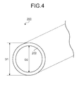
- Fig. 4 is a perspective view of the cylindrical cutting blade of the ultrasonic cutter.
- Figs. 5A to 5E are schematics for explaining the processes in each step of collecting the specimen.
- Fig. 6 is a top view of the thermal barrier coat while the specimen is collected.
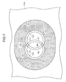
- Fig. 7 is a schematic of another example of the incision formed on the blade with the ultrasonic cutter.
- Fig. 5A depicts a state of the blade before being processed.
- Fig. 5B depicts a state of the blade when the cylindrical incision is formed in the thermal barrier coat.
- Fig. 5C depicts a state of the blade when a grinder is cutting an area around the cylindrical incision.
- Fig. 5D depicts a state of the blade when a rotating cutter having a disc-shaped cutting blade is cutting the base material 100 under the specimen.
- Fig. 5E depicts a state of the blade when the specimen is separated from the base material.
- an ultrasonic cutter 200 used in the present embodiment cuts a processing object member by minutely vibrating a cutting blade 202.
- the cutting blade 202 of the ultrasonic cutter 200 has a cylindrical shape, and a diameter D thereof is 3 millimeters to 5 millimeters.
- the cylindrical incision can be formed on the thermal barrier coat 110 by pushing the cutting blade 202 against the thermal barrier coat 110.
- an amount of the cutting blade fed that is, a distance (indicated by an arrow A shown in Fig. 4 ) the cutting blade 202 moved in the direction from the top coat 114 to the base material 100, can be monitored.
- cutting of the top coat 114 is started by vertically contacting the cylindrical cutting blade 202 onto the thermal barrier coat 110 from above and by vibrating the cutting blade 202. While cutting the top coat 114 and the bond coat 112, the cutting blade 202 is fed as much as the width of the thermal barrier coat 110 toward the base material 100 as indicated by the arrow A.
- Vibrating frequency of the cutting blade 202 of the ultrasonic cutter 200 is 1 kilohertz to 50 kilohertz. As the vibrating frequency increases, a cutting speed of the cutting blade 202, that is, a feeding speed thereof, can be higher. With the vibrating frequency equal to or larger than 50 kilohertz, however, the cutting speed is too high and the top coat 114 may be damaged. On the other hand, with the vibrating frequency equal to or smaller than 1 kilohertz, the cutting speed is equal to or lower than one hundredth of a standard condition described later. Thus, the cutting speed is significantly low. In the standard condition in the present embodiment, the vibrating frequency of the cutting blade 202 is set to be 25 kilohertz and the feeding speed of the cutting blade 202 is set to be 0.5 mm/min.
- Carborundum (SiC) is used as abrasive grain of the ultrasonic cutter 200.
- Abrasive grain having a grain size of #240 to #1000 that is, abrasive grain having a diameter of about 60 micrometers to 16 micrometers, is used in the ultrasonic cutter 200.
- a grain size is set to be #400, that is, a diameter of the abrasive grain is set to be about 30 micrometers. If a grain size is smaller than #240, that is, if a diameter of the abrasive grain is large, the cutting speed can be increased. However, with the speed, the cutting surface is more likely to be damaged. On the other hand, if a grain size is larger than #1000, that is, if a diameter of the abrasive grain is small, the cutting speed is significantly low.
- the thermal barrier coat 110 is cut until the cutting blade 202 of the ultrasonic cutter 200 comes in contact with a base material surface 100a that is a boundary between the base material 100 and the thermal barrier coat 110 (incision forming step).
- a cylindrical incision 121 can be formed on the thermal barrier coat 110.
- an area surrounded by the cylindrical incision 121 becomes a specimen 20 described later in detail.
- an inner edge 120 of the incision 121 is the edge of the specimen 20.
- the portion of the thermal barrier coat 110 located outside of the incision 121 is removed by using a tool such as a grinder so that a rotating cutter 220 having a disc-shaped cutting blade 222 (cutting unit) can be inserted to the base material 100 thereat at a later step. More specifically, as shown in Fig. 6 , the thermal barrier coat 110 neighboring the outer edge 122 of the incision 121 is cut from the outer edge 122 to an edge 130 that is located at a predetermined distance away from the edge 122 along the surface 100a of the base material 100. Thus, the incision 121 is expanded (incision expanding step). The edge 130 is continual to the surface 114a of the top coat 114 before the thermal barrier coat 110 is cut.
- the thermal barrier coat 110 is cut into a plate between the outer edge 122 of the incision 121 and the edge 130 located a predetermined distance away from the edge 122 so that as the distance from the outer edge 122 toward the edge 130 increases, the distance from the surface 100a of the base material 100 toward the surface 114a of the top coat 114 decreases. Accordingly, an area 133 in the thermal barrier coat 110 neighboring the outer edge 122 of the incision 121 is cut away as described above, the incision 121 is expanded outwardly and formed into a plate.
- the rotating cutter 220 having the cutting blade 222 (cutting unit) that is very thin and disc-shaped cuts a part 20a that becomes the specimen 20 later.
- the section of the part 20a cut by the rotating cutter 220 is situated closer to the base material 100 than the bond coat 112.
- the rotating cutter 220 has the cylindrical cutting blade 222, which is a disk provided with diamond abrasive grain by electrodepositing.
- the rotating cutter 220 can cut an area of a processing object member contacting the cutting blade 222 by rotating the disc-shaped cutting blade 222.
- the cutting blade 222 having a thickness T of 0.05 millimeter to 0.4 millimeter is used in the rotating cutter 220.
- the cutting blade having the cutting blade width T of 0.2 millimeter is used in the rotating cutter 220. If the cutting blade 222 having a cutting blade width smaller than 0.05 millimeter is used in the rotating cutter 220, the cutting blade 222 is bent while cutting the thermal barrier coat 110.
- a cutting edge 223 of the rotating cutter 220 is inserted to the part 20a that becomes the specimen 20 so that the bond coat 112 in the part 20a is not cut away.
- the rotating cutter 220 is inserted to the part 20a so that an angle between a disc surface 222a and the surface 100a of the base material 100 is as small as possible.
- the base material 100 is cut inwardly from the part 20a that later becomes the specimen 20 all around the inner edge 120 of the cylindrical incision 121.
- the specimen 20 is cut away from one of the blades 10 (11) (specimen cutting away step).
- the specimen can be collected that corresponds to an inner diameter of the cylindrical cutting blade 202 of the ultrasonic cutter 200.
- the specimen 20 thus obtained is used for evaluating the deterioration of the thermal barrier coat 110.
- the "inwardly” means in the direction from the incision 121 toward the center of the part 20a that later becomes the specimen, that is, the direction radially inward the cylindrical incision 121.
- a part 110c of the base material 100 is also cut away along with the top coat 114 and the bond coat 112 of the specimen 20.
- a depression 110e that is a trace of the part 110c of the base material 100 that is cut away from the base material 100 is formed on the base material 100. If a depth B of a depression 100e from the surface 100a of the base material 100 is about 0.5 millimeter, by forming the thermal barrier coat 110 again at the depression 100e, the blade 10 (11) having the depression 100e can be used again as the blade 10 (11) of the turbine 5 of the gas turbine 1.
- the present embodiment includes the step of forming the cylindrical incision 121 from the surface 114a of the thermal barrier coat 110 to the surface of the base material 100 with the ultrasonic cutter 200 having the cylindrical cutting blade 202 and the step of cutting away the specimen 20 by cutting the thermal barrier coat 110 inwardly from the cylindrical incision 121 with the rotating cutter 220 having the disc-shaped cutting blade 222.
- the specimen 20 including the thermal barrier coat 110 can be obtained while minimizing the impact force applied to the thermal barrier coat 110.
- optical observation of the oxide scale layer 112s can be accurately performed, such as measuring a thickness of an oxide scale layer 112a formed on the bond coat 112 of the thermal barrier coat 110 provided on the blade 10 (11).
- deterioration of the thermal barrier coat 110 can be evaluated without replacing the blade 10 (11) of the turbine 5.
- the incision 121 is expanded by cutting the thermal barrier coat 110 situated outside of the incision 121 all around the incision 121 after the incision 121 is formed by using the ultrasonic cutter 200. Then, the thermal barrier coat 110 is cut by the rotating cutter 220 inwardly from the incision 121. Because the rotating cutter 220 is inserted to the incision 121 after the incision is expanded outwardly, the rotating cutter 220 can be inserted to the thermal barrier coat 110 so that an angle between the rotating cutter 220 and the surface of the base material 100 is as small as possible even if the difference between the inner diameter D2 and the external diameter D1 provided by the ultrasonic cutter 200 is small and a distance between the inner edge 120 and the outer edge 122 of the incision 121 is small.
- an amount of the base material 100 cut away along with the thermal barrier coat 110 in the specimen 20 can be made as small as possible, and the depression 100e formed on the base material 100 after the specimen 20 is cut away from the thermal barrier coat 110 can be as shallow as possible.
- only one cylindrical incision 121 that is round shaped is formed with the ultrasonic cutter 200.
- examples of the incision 121 are not limited thereto.
- a plurality of incisions 121c and 121f can preferably be formed so that the incisions 121c and 121f partially overlap.
- a ratio between the total surface of the specimens that can be obtained (20c, 20e, and 20f) and a surface of a region 135 that is outwardly expanded from the incisions 121c and the 121f can be smaller than when only one incision 121 is formed.
- the specimens 20c, 20e, and 20f can be obtained while minimizing the step of outwardly expanding the incision 121, which is cumbersome compared to other steps.
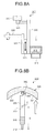
- FIG. 8A is a front view of a discharge wire cutting device.
- Fig. 8B is a side view of the discharge wire cutting device.
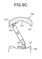
- Figs. 9A to 9C are schematics for explaining operation performed by the discharge wire cutting device.
- Fig. 9A depicts a state where when an electrode of the discharge wire cutting device is entering the incision formed in the thermal barrier coat.
- Fig. 9B depicts a state where the electrode moves along the surface of the base material, while cutting the thermal barrier coat by utilizing electric discharge.
- FIG. 9C depicts a state where the electrode is exiting the incision after finishing cutting the specimen.
- the present embodiment is different from the first embodiment in that the discharge wire cutting device is used in place of the rotating cutter to cut the specimen of the thermal barrier coat.
- the present embodiment is described below in greater detail. Configurations of the gas turbine, the blades, and the thermal barrier coat are similar to that of the first embodiment. Accordingly, the gas turbine, the blades, and the thermal barrier coat are given the identical reference characteristics and detail descriptions thereof are omitted.
- a discharge wire cutting device 300 includes: an electrode 310 having a U-shaped wire and can cut metal with electrical discharge; and an electrode holder 315 that holds the electrode 310. Electrical power is supplied from a power supply (not shown) to the electrode 310.
- the electrode 310 can cut the blade 10 (11) by generating electrical discharge between the blade 10 (11), that is a metal member and a processing object member, and the electrode 310
- the discharge wire cutting device 300 includes a rotating shaft 330 that rotates the electrode holder 315, a sliding mechanism 320 connected to the rotating shaft 330 via a stay 325, and the stay 325 that transmits, to the electrode holder 315, rotating movement of the rotating shaft 330 that transmits movement of a roller 340 to the electrode holder 315.
- the rotating shaft 330 is connected to a motor (not shown), and is rotated about a shaft center C of the rotating shaft 330.
- the rotating movement of the rotating shaft 330 is transmitted from the stay 325 to the electrode holder 315 via the later described sliding mechanism 320.
- the electrode 310 can be rotated in the circumferential direction of the rotating shaft 330.
- the discharge wire cutting device 300 further includes: the sliding mechanism 320 that enables the electrode 310 and the electrode holder 315 to slide in the radial direction of the rotating shaft 330; a guiding slide 350 on which outline surfaces (profile surfaces 351, 352, and 353) are provided that defines movement of the electrode 310 in the radial direction; the roller 340 that moves along the outline surfaces 351, 352, and 353 of the guiding slide 350; a rod that transmits movement of the roller 340 in the radial direction of the rotating shaft 330 to the electrode holder 315 and the electrode 310.
- the sliding mechanism 320 that enables the electrode 310 and the electrode holder 315 to slide in the radial direction of the rotating shaft 330
- the roller 340 that moves along the outline surfaces 351, 352, and 353 of the guiding slide 350
- a rod that transmits movement of the roller 340 in the
- the roller 340 is rotatably supported with respect to a rod 335, and moves along the outline surfaces (351, 352, and 353) of the guiding slide 350.
- the rod 335 biases the roller 340 with a spring (not shown) in the radial direction of the rotating shaft 330 toward the outline surfaces (351, 352, and 353) of the guiding slide 350.
- the roller 340 can move along the outline surfaces (351, 352, and 353) of the guiding slide 350, and the rod 335 is driven in the radial direction of the rotating shaft 330 according to the outline of the guiding slide 350.
- the electrode holder 315 is connected to the rod 335, and is connected to the rotating shaft 330 via the sliding mechanism 320.
- the electrode 310 slides in the radial direction of the rotating shaft 330 by a distance that corresponds to a difference made on the cross-sectional shape of the outline surface (351, 352, and 353) of the guiding slide 350 from the shape of the circle of which the center is the shaft center C of the rotating shaft 330. That is, in the discharge wire cutting device 300, by setting the cross-sectional shape of the outline surfaces (351, 352, and 353) of the guiding slide 350, a distance E between the shaft center C of the rotating shaft 330 and the electrode 310 can be adjusted to be a desired value corresponding to a rotating angle position of the electrode 310.
- the cylindrical incision 121 is formed from the thermal barrier coat 110 to the base material 100 with the ultrasonic cutter 200 having the cylindrical cutting blade 202 (incision forming step).
- the incision 121 is outwardly expanded by cutting away the thermal barrier coat 110 situated radially outward of the outer edge of the incision 121 (incision expanding step).
- the blade 10 (11) on which the incision 121 is formed is fitted to the discharge wire cutting device 300 as shown in Fig. 9A .
- the rotating shaft 330 is rotated by controlling the motor (not shown) and an electric voltage is applied to the electrode 310, and thus, electrical discharge is generated.
- the roller 340 moves along a first surface 351 of the outline surfaces (351, 352, and 353) of the guiding slide 350, and thus, the electrode 310 moves in a rotating manner in the circumferential direction of the rotating shaft 330. As a result, the electrode 310 enters the incision 121.
- the roller 340 moves along a second surface 352 that is situated in the middle of the outline surfaces (351, 352, and 353), as shown in Fig. 9B .
- the depression 100e is formed so that the electrode 310 slides more toward the side of the guiding slide 350 in the radial direction of the rotating shaft 330 than in the first surface 351.
- the shape of the second surface 352 is configured so that the electrode 310, that is provided on the other side of the roller 340 with the rotating shaft 330 in the center between each other, moves along the surface 100a of the base material 100 and the thermal barrier coat 110 in parallel thereto when the roller 340 moves along the second surface 352.
- the electrode 310 moves along the surface 100a, and the electrode 310 cuts along the surface 100a of the base material 100 by generating electrical discharge between the electrode 310 and the thermal barrier coat 110 and the base material 100 (specimen cutting away step).
- the discharge wire cutting device 300 can cut away the specimen 20 of the thermal barrier coat 110 from the surface of the blade 10 (11).
- the discharge wire cutting device 300 in which the distance E between the rotating shaft 330 and the electrode 310 can be adjusted to a desired value corresponding to the rotating angle position of the electrode 310, is used to cut the thermal barrier coat 110 inwardly from the cylindrical incision 121 to cut away the specimen 20. Therefore, an amount of the base material 100 contained in the specimen 20 of the thermal barrier coat 110 can be minimized.
- the discharge wire cutting device 300 includes the guiding slide 350, the roller 340 that moves along the outline surfaces (351, 352, and 353) of the guiding slide 350, and the roller 340 that rotatably instructs the roller 340 and that is connected to the electrode holder 315.
- the configuration of the discharge wire cutting device 300 according to the present invention is not limited thereto.
- the discharge wire cutting device 300 may take any configurations as long as the distance E between the rotating shaft 330 and the electrode 310 can be adjusted to desired value corresponding to a rotating angle position of the electrode 310.
- the discharge wire cutting device 300 may be configured without the guiding slide 350, the roller 340, and the rod 335, and an actuator that is extendable with a control device can be provided in place of the sliding mechanism 320 that holds the electrode holder 315.
- a method is described that estimates a "metal temperature", i.e., a temperature of the base material, from the specimen of the thermal barrier coat obtained with the collecting method of the specimen according to the first or the second embodiment.
- a metal temperature i.e., a temperature of the base material.
- the present embodiment is described below in detail.
- configurations of the gas turbine, the blades, and the thermal barrier coat are similar to that of the first embodiment. Accordingly, the gas turbine, the blades, and the thermal barrier coat are given the identical reference characteristics and the detail descriptions thereof are omitted.
- a metal temperature estimating method In a metal temperature estimating method according to the present embodiment of estimating a metal temperature of the blade 10 (11) in which the bond coat 112 and the top coat 114 are sequentially formed on the base material 100, relationships between a thickness, a temperature, and a time of the oxide scale layer 112s are obtained in advance from a test piece having the same composition as the blade 10 (11). Then, utilizing the relationships, a metal temperature of the blade 10 (11) is estimated based on a thickness of the oxide scale layer 112s of the specimen 20 obtained from the gas turbine 1.
- the timing of the deterioration of the blade 10 (11) such as separation of the top coat 114 can be predicted, and a remnant service life of the blade 10 (11) can be evaluated.
- the deterioration of the blade can be evaluated at low cost because the blade needs not to be replaced.
- a metal temperature estimating method In a metal temperature estimating method according to the present embodiment of estimating a metal temperature of the blade 10 (11) in which the bond coat 112 and the top coat 114 are sequentially formed on the base material 100, relationships between a disappearing depth, a temperature, and a time of a deposition substance formed on the surface side of the blade 10 (11) is obtained in advance from a test piece having the same composition as the blade 10 (11). Then, utilizing the relationships, a metal temperature of the blade 10 (11) is estimated based on a disappearing depth of a deposition substance formed on the specimen 20 obtained from the gas turbine 1. Also with the method, the timing of the deterioration of the blade 10 (11) such as separation of the top coat 114 can be predicted, and a remnant service life of the blade 10 (11) can be evaluated.
- a metal temperature estimating method In a metal temperature estimating method according to the present embodiment of estimating a metal temperature of the blade 10 (11) in which the bond coat 112 is formed on the base material 100, a relationship between a thickness and a temperature of a diffuse layer formed on the surface of the base material 100, and time is obtained in advance from a test piece having the same composition as the blade 10 (11). Then, utilizing the relationships, a metal temperature of a component that is at a high temperature is estimated based on a thickness of a diffuse layer of the specimen 20 obtained from the gas turbine 1. Also with the method, the timing of the deterioration of the blade 10 (11) such as separation of the top coat 114 can be predicted, and a remnant service life of the blade 10 (11) can be evaluated.
- a metal temperature estimating method In a metal temperature estimating method according to the present embodiment of estimating a metal temperature of the blade 10 (11) in which the bond coat 112 is formed on the base material 100, a relationship between a disappearing depth of a deposition substance formed on the blade 10 (11) on the side of the base material 100, a temperature of the base material 100, and time is obtained in advance from a test piece having the same composition as the blade 10 (11). Then, utilizing the relationship, a metal temperature of a component that is at a high temperature is estimated based on a disappearing depth of a deposition substance formed on the specimen 20 obtained from the gas turbine 1. Also with the method, the timing of the deterioration of the blade 10 (11) such as separation of the top coat 114 can be predicted, and a remnant service life of the blade 10 (11) can be evaluated.
- a temperature of the top coat 114 of the blade 10 (11) is estimated based on the specimen 20 of the thermal barrier coat 110 obtained according to a collecting method of the specimen 20 according to the first or the second embodiment.
- the present embodiment is described below in detail.
- configurations of the gas turbine, the blade 10 (11), and the thermal barrier coat 110 are similar to the first embodiment. Accordingly, the gas turbine, the blade, and the thermal barrier coat are given the identical reference characteristics and the detail descriptions thereof are omitted.
- a temperature of the blade 10 (11) in which the top coat 114 that is a ceramic layer is formed on the base material 100 is estimated.
- An amount of monoclinic crystal formed on the top coat 114 is measured by using X-ray crystallography, and then, based on the amount of the monoclinic crystal, a surface temperature of the top coat 114 is estimated.
- the surface temperature of the top coat 114 can be nondestructively estimated. Accordingly, the timing of the deterioration of the blade 10 (11) such as separation of the top coat 114 can be predicted, and a remnant service life of the blade 10 (11) can be evaluated. With the method, the deterioration of the blade can be evaluated at low cost because the blade needs not to be replaced.
- a temperature estimating method of the blade 10 (11) in which the top coat 114 is formed on the base material 100 an surface rate of a film shaped defect is obtained by performing image processing of a microstructure of the cross-section, along the direction of the depth of the top coat 114, of the obtained specimen 20. Based on the surface rate, a surface temperature of the top coat 114 is estimated. Also with the method, the timing of the deterioration of the blade 10 (11) such as separation of the top coat 114 can be predicted, and a remnant service life of the blade 10 (11) can be evaluated.
- a hardness of the cross-section of the top coat 114 along the direction of depth of the top coat 114 is obtained. Based on the hardness, a surface temperature of the top coat 114 is estimated. Also with the method, the timing of the deterioration of the blade 10 (11) such as separation of the top coat 114 can be predicted, and a remnant service life of the blade 10 (11) can be evaluated.
- the bond coat 112 that is an oxidation resistant layer and the top coat 114 that is a ceramic layer are sequentially provided on the base material 100 as the thermal barrier coat 110, and the specimen 20 is constituted mainly of the bond coat 112 and the top coat 114.
- the configurations of the thermal barrier coat 110 and the specimen 20 are not limited thereto.
- an oxidation resistant layer may separately be provided between the bond coat provided on the base material and the top coat that constitutes the surface of the blade.
- the method of collecting a specimen according to the present embodiment is useful in evaluating the deterioration of a thermal barrier coat provided on a blade of a turbine, and more particularly, for evaluating the deterioration of a blade of an industrial gas turbine.
Landscapes
- Physics & Mathematics (AREA)
- Health & Medical Sciences (AREA)
- Life Sciences & Earth Sciences (AREA)
- Chemical & Material Sciences (AREA)
- Analytical Chemistry (AREA)
- Biochemistry (AREA)
- General Health & Medical Sciences (AREA)
- General Physics & Mathematics (AREA)
- Immunology (AREA)
- Pathology (AREA)
- Sampling And Sample Adjustment (AREA)
- Analysing Materials By The Use Of Radiation (AREA)
- Turbine Rotor Nozzle Sealing (AREA)
Abstract
Description
- The present invention relates to a specimen collecting method for collecting a specimen from a member provided with a layer on a surface thereof, and more particularly, to a specimen collecting method for collecting a specimen from a surface of a blade used for a gas turbine and to a blade temperature estimating method.
- An approach for providing thermal barrier coating on a surface of a base material of a component is known to improve heat resistance of the base material. For example, in a gas turbine, an approach for providing thermal barrier coating on surfaces of a rotor blade and a stationary blade that are included in the turbine is known.
- A member formed on a surface of a component by thermal barrier coating (hereinafter, "thermal barrier coat") is generally composed of two layers: an external layer called a top coat, and a layer called a bond coat that joins the top coat and the base material together. In a thermal barrier coat for a gas turbine, a ceramic having low thermal conductivity is used as the top coat, and an alloy having excellent oxidation resistance is used as the bond coat.
- When the thermal barrier coat is exposed to a high temperature for a long time, a thermally grown oxide (hereinafter, "oxide scale layer") oxidized by the heat from the top coat, may be generated on the side of the bond coat facing the top coat. The oxide scale layer is generated on an area of the bond coat in contact with the top coat, and expands as thermal load applied to the thermal barrier coat increases. As the oxide scale layer expands and the thickness thereof increases, the oxide scale layer pushes up the top coat to, for example, form a crack on the top coat. As a result, the top coat may be separated from the base material and the bond coat.
- To detect the separation of the thermal barrier coat in advance, an approach for estimating deterioration of the thermal barrier coat, that is, the degree of damage onto the barrier coat, is called for. In a technology disclosed in
Patent Document 1, an impact force is applied to a thermal barrier coat. For example, a spherical object is collided thereagainst. Thus, the thermal barrier coat is destroyed, and information about deterioration of the thermal barrier coat can be obtained according to the condition of damage, such as the separation, provided thereto. - Patent Document 1: Japanese Patent Application Laid-open No.
2002-277383 - In the technology disclosed in
Patent Document 1, a strong impact force is applied to the thermal barrier coat and thus, structure thereof is destroyed. Therefore, the technology disclosed therein is not suitable for optically observing the thermal barrier coat and obtaining information about deterioration thereof. - The oxide scale layer is very thin, that is, the thickness thereof is 20 micrometers at most, and is not an oxide having a simple composition. Therefore, it is difficult to obtain information about condition of the oxide scale layer of the thermal barrier coating with a nondestructive approach.
- More specifically, when deterioration of a blade thermal barrier coat provided on a blade of a gas turbine is evaluated, for example, the blade is cut away from the gas turbine, and thus, the thermal barrier coat is destroyed along with the components provided on the blade. Accordingly, each time the thermal barrier coat is evaluated, new components are required to be mounted on the blade in place of the destroyed components.
- In view of the foregoing, it is an object of the present invention to provide a specimen collecting method that makes it possible to collect a specimen from a surface of a member without damaging the member and a blade temperature estimating method that makes it possible to estimate a temperature of a blade of a gas turbine without destroying the blade.
- According to an aspect of the present invention, a specimen collecting method of collecting a specimen from a member whose surface is provided with a layer, includes: an incision forming step of forming a cylindrical incision by feeding a cylindrical cutter having a cylindrical cutting blade from the surface in the direction of thickness of the member to perform cutting; and a specimen cutting away step of cutting away a specimen formed inside the incision by inwardly cutting the member from the cylindrical incision.
- Advantageously, the specimen collecting method further includes an incision expanding step of cutting the member so that the incision is outwardly expanded after forming the cylindrical incision. A rotating cutter having a disc-shaped cutting blade is inserted to the cylindrical incision to cut the member at the specimen cutting away step.
- Advantageously, in the specimen collecting method, the member is a blade of a gas turbine, a surface of the blade is formed by providing a layer of a thermal barrier coat on a base material, the cylindrical cutter is fed until the cylindrical cutter comes in contact with the base material at the incision forming step, and the rotating cutter cuts the base material at the specimen cutting away step.
- Advantageously, in the specimen collecting method, a plurality of incisions is formed so that the incisions partially overlap at the incision forming step.
- According to another aspect of the present invention, a temperature estimating method of a blade in which a bond coat and a top coat are sequentially formed on a base material uses a specimen obtained by the specimen collecting method described above. A relationship between a thickness and a temperature of an oxide scale layer of the blade, and time is obtained based on a test piece having a same composition as the blade, and then, by utilizing the relationship, a metal temperature of the blade is estimated based on the thickness of the oxide scale layer of the specimen obtained from the gas turbine.
- According to another aspect of the present invention, a temperature estimating method of a blade formed with a top coat that is a ceramic layer on a base material uses a specimen obtained by the specimen collecting method described above. An amount of a monoclinic crystal formed on the top coat of the obtained specimen is measured by X-ray diffraction method, and a surface temperature of the top coat is estimated based on the amount of the monoclinic crystal.
- The specimen collecting method according to the present invention includes an incision forming step of forming a cylindrical incision by using a cylindrical cutter having a cylindrical cutting blade and a specimen collecting method of cutting away a specimen by cutting a member inwardly from the cylindrical incision. Therefore, when the specimen is collected from the member, the specimen can be obtained from the surface thereof by applying thereto as less impact force as possible. Thus, accurate optical observation of the member can be implemented.
- The specimen collecting method according to the present invention may further include an incision expanding step of cutting the member so that the incision is expanded outwardly after the cylindrical incision is formed on the member. Therefore, even if the difference between the inner diameter and the external diameter of the cylindrical cutter is small, and thus, the distance between the inner edge and the outer edge of the incision is also small, the rotating cutter can be inserted into the member so that an angle formed between the rotating cutter and the surface of the member is as acute as possible. As a result, the specimen cut away from the member can be as thin as possible. Therefore, a depression formed on the member after the specimen is cut away therefrom can be as shallow as possible.
- In the specimen collecting method according to the present invention, the member is a blade of a gas turbine. The surface of the blade is configured so that a thermal barrier coat layer is formed thereon. At the incision forming step, the cylindrical cutter is fed into the blade until the cylindrical cutter comes in contact with the base material. At the specimen cutting away step, the rotating cutter cuts the base material. Thus, a specimen of a thermal barrier coat of a blade of a gas turbine can be collected with a small damage applied to the specimen. Therefore, without replacing the blade of the gas turbine after destroying the blade, an oxide scale layer can be evaluated to evaluate the deterioration of the blade.
- In the specimen collecting method according to the present invention, a plurality of cylindrical incisions is formed so that the cylindrical incisions overlap partially. Therefore, a ratio between a total surface of specimens thus obtained and a surface of an area expanded outwardly from the incisions can be smaller than the case where only a single incision is formed. Accordingly, while minimizing a cumbersome step of expanding the incisions, a plurality of specimen can be obtained.
- In the blade temperature estimating method according to the present invention, a relationship between a width and a temperature of the oxide scale layer of the blade, and time is first obtained based on a test piece having the composition similar to the composition of the blade. Thereafter, based on the relationship, the temperature of the blade can be estimated according to the thickness of the oxide scale layer of the specimen obtained from the gas turbine. Thus, while minimizing the damage applied to the blade, a temperature of the blade can be estimated. As a result, it is not necessary to replace the blade to obtain a specimen, and thus, deterioration of the blade can be evaluated at low cost.
- In the blade temperature estimating method according to the present invention, a specimen is obtained with the specimen collecting method, and an amount of a monoclinic crystal generated on the top coat is measured with an X-ray diffraction method. Then, a temperature of the surface of the top coat is estimated based on the amount of the monoclinic crystal. Therefore, a temperature of the blade can be estimated while minimizing damage applied to the blade. As a result, it is not necessary to replace the blade to obtain a specimen, and thus, deterioration of the blade can be evaluated at low cost.
-
- [
Fig. 1] Fig. 1 is longitudinal sectional view of an overall configuration of a gas turbine according to a first embodiment of the present invention. - [
Fig. 2] Fig. 2 is a sectional view of a blade according to the first embodiment. - [
Fig. 3A] Fig. 3A is a schematic of an example of a thermal barrier coat provided on the blade according to the first embodiment. - [
Fig. 3B] Fig. 3B is a schematic of a state of the thermal barrier coat when an oxide scale portion is generated within the thermal barrier coat according to the first embodiment. - [
Fig. 4] Fig. 4 is a perspective view of a cylindrical cutting blade of an ultrasonic cutter according to the first embodiment. - [
Fig. 5A] Fig. 5A is a schematic for explaining a process in each step of collecting a specimen according to the first embodiment, in which a state of the blade before being processed is shown. - [
Fig. 5B] Fig. 5B is a schematic for explaining a process in each step of collecting a specimen according to the first embodiment, in which a state of the blade when a cylindrical incision is formed in the thermal barrier coat is shown. - [
Fig. 5C] Fig. 5C is a schematic for explaining a process in each step of collecting a specimen according to the first embodiment, in which a state of the blade when a grinder is cutting an area around the cylindrical incision is shown. - [
Fig. 5D] Fig. 5D is a schematic for explaining a process in each step of collecting a specimen according to the first embodiment, in which a state of the blade when a rotating cutter having a disc-shaped cutting blade is cutting the base material under the specimen is shown. - [
Fig. 5E] Fig. 5E is a schematic for explaining a process in each step of collecting a specimen according to the first embodiment, in which a state of the blade when the specimen is cut away from the base material is shown. - [
Fig. 6] Fig. 6 is a top view of the thermal barrier coat while the specimen is collected according to the first embodiment. - [
Fig. 7] Fig. 7 is a schematic of another example of the incision formed on the blade with the ultrasonic cutter. - [
Fig. 8A] Fig. 8A is a front view of a discharge wire cutting device according to a second embodiment of the present invention. - [
Fig. 8B] Fig. 8B is a side view of the discharge wire cutting device according to the second embodiment. - [
Fig. 9A] Fig. 9A is a schematic for explaining an operation performed by the discharge wire cutting device according to the second embodiment, in which an electrode of the discharge wire cutting device entering into the incision formed in the thermal barrier coat is shown. - [
Fig. 9B] Fig. 9B is a schematic for explaining an operation performed by the discharge wire cutting device according to the second embodiment, in which the electrode moving along the surface of the base material while cutting the specimen is shown. - [
Fig. 9C] Fig. 9C is a schematic for explaining an operation performed by the discharge wire cutting device according to the second embodiment, in which the electrode exiting the incision after the cutting of the specimen is completed is shown. -
- 1
- gas turbine
- 3
- compressor
- 5
- turbine
- 10
- stationary blade (blade)
- 11
- rotor blade (blade)
- 20
- specimen
- 20c
- specimen
- 20e
- specimen
- 20f
- specimen
- 100
- base material
- 100a
- base material surface
- 110
- thermal barrier coat
- 112
- bond coat
- 112s
- oxide scale layer
- 114
- top coat
- 114a
- surface (blade surface)
- 120
- inner edge
- 121
- incision
- 122
- outer edge
- 200
- ultrasonic cutter (cylindrical cutter)
- 202
- cutting blade (cylindrical cutting blade)
- 220
- rotating cutter
- 222
- cutting blade (disc-shaped cutting blade)
- 300
- discharge wire cutting device (discharge sampling device)
- 310
- electrode
- 315
- electrode holder
- 320
- sliding mechanism
- 330
- rotating shaft
- 340
- roller
- Exemplary embodiments according to the present invention are described below in detail with reference to the accompanying drawings. The present invention is not, however, limited thereto. The elements described in embodiments below include various modifications that will readily occur to those skilled in the art or modifications substantially similar thereto.
- A gas turbine and a thermal barrier coat provided on a blade of the turbine to which a collecting method of a thermal barrier coat specimen according to a first embodiment of the present invention is applied are described below in detail with reference to
Figs. 1 to 3B .Fig. 1 is a longitudinal sectional view of an overall configuration of the gas turbine.Fig. 2 is a sectional view of the blade.Fig. 3A is a schematic of an example of a thermal barrier coat provided on the blade, andFig. 3B is a schematic of a state of the blade when an oxide scale layer is formed within the thermal barrier coat. Only substantial parts related to the present invention are schematically shown inFigs. 1 and2 .Figs. 3A and 3B are enlarged views of an area surrounded by a chain double-dashed line B shown inFig. 2 . - As shown in
Fig. 1 , anindustrial gas turbine 1 according to the present embodiment includes anair intake 2, a compressor 3, a combustor 4, and aturbine 5, which are arranged in the described order from the upstream side to the downstream side in the air flow direction. Air taken into the gas turbine through theair intake 2 is compressed by the compressor 3 to produce compressed air that is at high temperature and high pressure. The compressed air is supplied to the combustor 4. The combustor 4 supplies the compressed air with gas fuel such as natural gas or liquid fuel such as diesel oil and heavy oil, and then, burns the fuel to produce combustion gas that is at high temperature and high pressure. The high temperature and high pressure combustion gas generated at the combustor 4 is supplied to theturbine 5. - In the
turbine 5,stationary blades 10 androtor blades 11 are alternately arranged. Theturbine 5 converts energy of the combustion gas supplied from the combustor 4 into rotary torque through thestationary blades 10 and therotor blades 11. A part of mechanical power received from the combustion gas by theturbine 5 is used to drive the compressor 3, and the rest of the mechanical power is used for purposes such as generating electric power. Here, the "blade" means a rotor blade or a stationary blade. - As shown in
Fig. 2 , the blades 10 (11) are configured so that all around the cross section of each of the blades 10 (11), a layer ofthermal barrier coat 110 is provided on asurface 100a of abase material 100. Thethermal barrier coat 110 is provided on thesurface 100a of thebase material 100 by performing vapor deposition or thermal spraying on thesurface 100a. Because thethermal barrier coat 110 is provided on the blades 10 (11), a temperature (metal temperature) of thebase material 100 can be lower than a temperature (for example, at 1500 degrees centigrade) of the combustion gas contacting the blades 10 (11). - As shown in
Fig. 3A , thethermal barrier coat 110 according to the present embodiment includes atop coat 114 that is an external layer constituting an outer surface of each of the blades 10 (11) and abond coat 112 that is a metal bonding layer bonding thetop coat 114 and thebase material 100 together. MCrAlY alloy (M: Ni, Co, Fe, or other metals) that is excellent in oxidation resistance is used as a material for thebond coat 112. The alloy is applied to thebase material 100 by performing low pressure plasma spraying, and thus, thebond coat 112 is formed thereon. On the other hand, zirconium ceramic is used as a material for thetop coat 114. The ceramic is applied to thebond coat 112 by performing air plasma spray or electron beam physical vapor deposition, and thus, thetop coat 114 is formed thereon. - The
top coat 114 is provided with a heat shielding property by, for example, having a plurality of pores formed at the interior thereof. Thetop coat 114 reduces a temperature of thebase material 100 so that the temperature is lower than a temperature of the combustion gas contacting asurface 114a of thebase material 100.
Thebond coat 112 bonds thetop coat 114 and thebase material 100 together, and prevents thebase material 100 from oxidizing due to the combustion gas and heat thereof entering into thetop coat 114. Thesurface 114a of thetop coat 114 is the surface of each of the blades 10 (11). - When the
gas turbine 1 configured as described above is in operation for a long time, in thethermal barrier coat 110 of each of therotor blades 11 and thestationary blades 10, anoxide scale layer 112s that is a oxide is generated as shown inFig. 3B on the area in thebond coat 112 that is at the boundary between thebond coat 112 and thetop coat 114 as shown inFig. 3B . An area of theoxide scale layer 112s expands (grows) as thermal load applied thereto increases. Thus, thetop coat 114 is pushed up in the direction away from thebase material 100. Thus, a crack may be formed in thetop coat 114, or sometimes thetop coat 114 may be separated from thebase material 100. - In the present embodiment, an ultrasonic cutter having a cylindrical cutting blade (cutting unit) is employed to collect a specimen of the thermal barrier coat from the surface of a blade of the gas turbine to obtain information about a status of generation of the
oxide scale layer 112s in thethermal barrier coat 110. A method for collecting a specimen of the thermal barrier coat is described below in detail with reference toFigs. 4 to 7 .Fig. 4 is a perspective view of the cylindrical cutting blade of the ultrasonic cutter.Figs. 5A to 5E are schematics for explaining the processes in each step of collecting the specimen.Fig. 6 is a top view of the thermal barrier coat while the specimen is collected.Fig. 7 is a schematic of another example of the incision formed on the blade with the ultrasonic cutter. -
Fig. 5A depicts a state of the blade before being processed.Fig. 5B depicts a state of the blade when the cylindrical incision is formed in the thermal barrier coat.Fig. 5C depicts a state of the blade when a grinder is cutting an area around the cylindrical incision.Fig. 5D depicts a state of the blade when a rotating cutter having a disc-shaped cutting blade is cutting thebase material 100 under the specimen.Fig. 5E depicts a state of the blade when the specimen is separated from the base material. - As shown in
Fig. 4 , anultrasonic cutter 200 used in the present embodiment cuts a processing object member by minutely vibrating acutting blade 202. Thecutting blade 202 of theultrasonic cutter 200 has a cylindrical shape, and a diameter D thereof is 3 millimeters to 5 millimeters. With theultrasonic cutter 200, the cylindrical incision can be formed on thethermal barrier coat 110 by pushing thecutting blade 202 against thethermal barrier coat 110. With theultrasonic cutter 200, an amount of the cutting blade fed, that is, a distance (indicated by an arrow A shown inFig. 4 ) thecutting blade 202 moved in the direction from thetop coat 114 to thebase material 100, can be monitored. - As shown in
Fig. 5A , cutting of thetop coat 114 is started by vertically contacting thecylindrical cutting blade 202 onto thethermal barrier coat 110 from above and by vibrating thecutting blade 202. While cutting thetop coat 114 and thebond coat 112, thecutting blade 202 is fed as much as the width of thethermal barrier coat 110 toward thebase material 100 as indicated by the arrow A. - Vibrating frequency of the
cutting blade 202 of theultrasonic cutter 200 is 1 kilohertz to 50 kilohertz. As the vibrating frequency increases, a cutting speed of thecutting blade 202, that is, a feeding speed thereof, can be higher. With the vibrating frequency equal to or larger than 50 kilohertz, however, the cutting speed is too high and thetop coat 114 may be damaged. On the other hand, with the vibrating frequency equal to or smaller than 1 kilohertz, the cutting speed is equal to or lower than one hundredth of a standard condition described later. Thus, the cutting speed is significantly low. In the standard condition in the present embodiment, the vibrating frequency of thecutting blade 202 is set to be 25 kilohertz and the feeding speed of thecutting blade 202 is set to be 0.5 mm/min. - Carborundum (SiC) is used as abrasive grain of the
ultrasonic cutter 200. Abrasive grain having a grain size of #240 to #1000, that is, abrasive grain having a diameter of about 60 micrometers to 16 micrometers, is used in theultrasonic cutter 200. In the standard condition in the present embodiment, a grain size is set to be #400, that is, a diameter of the abrasive grain is set to be about 30 micrometers. If a grain size is smaller than #240, that is, if a diameter of the abrasive grain is large, the cutting speed can be increased. However, with the speed, the cutting surface is more likely to be damaged. On the other hand, if a grain size is larger than #1000, that is, if a diameter of the abrasive grain is small, the cutting speed is significantly low. - As shown in
Fig. 5B , thethermal barrier coat 110 is cut until thecutting blade 202 of theultrasonic cutter 200 comes in contact with abase material surface 100a that is a boundary between thebase material 100 and the thermal barrier coat 110 (incision forming step). Thus, as shown inFig. 6 , acylindrical incision 121 can be formed on thethermal barrier coat 110. In thethermal barrier coat 110, an area surrounded by thecylindrical incision 121 becomes aspecimen 20 described later in detail. In other words, aninner edge 120 of theincision 121 is the edge of thespecimen 20. - As shown in
Fig. 5C , the portion of thethermal barrier coat 110 located outside of theincision 121 is removed by using a tool such as a grinder so that arotating cutter 220 having a disc-shaped cutting blade 222 (cutting unit) can be inserted to thebase material 100 thereat at a later step. More specifically, as shown inFig. 6 , thethermal barrier coat 110 neighboring theouter edge 122 of theincision 121 is cut from theouter edge 122 to anedge 130 that is located at a predetermined distance away from theedge 122 along thesurface 100a of thebase material 100. Thus, theincision 121 is expanded (incision expanding step). Theedge 130 is continual to thesurface 114a of thetop coat 114 before thethermal barrier coat 110 is cut. That is, thethermal barrier coat 110 is cut into a plate between theouter edge 122 of theincision 121 and theedge 130 located a predetermined distance away from theedge 122 so that as the distance from theouter edge 122 toward theedge 130 increases, the distance from thesurface 100a of thebase material 100 toward thesurface 114a of thetop coat 114 decreases. Accordingly, anarea 133 in thethermal barrier coat 110 neighboring theouter edge 122 of theincision 121 is cut away as described above, theincision 121 is expanded outwardly and formed into a plate. - As shown in
Fig. 5D , therotating cutter 220 having the cutting blade 222 (cutting unit) that is very thin and disc-shaped cuts apart 20a that becomes thespecimen 20 later. The section of thepart 20a cut by therotating cutter 220 is situated closer to thebase material 100 than thebond coat 112. - The
rotating cutter 220 has thecylindrical cutting blade 222, which is a disk provided with diamond abrasive grain by electrodepositing. Therotating cutter 220 can cut an area of a processing object member contacting thecutting blade 222 by rotating the disc-shapedcutting blade 222. Thecutting blade 222 having a thickness T of 0.05 millimeter to 0.4 millimeter is used in therotating cutter 220. In the present embodiment, the cutting blade having the cutting blade width T of 0.2 millimeter is used in therotating cutter 220. If thecutting blade 222 having a cutting blade width smaller than 0.05 millimeter is used in therotating cutter 220, thecutting blade 222 is bent while cutting thethermal barrier coat 110. On the other hand, it is not favorable to use thecutting blade 222 having a width that is larger than 0.4 millimeter in therotating cutter 220 because a "cutting overlap width" becomes larger therewith, and thus, the area of thebase material 100 cut becomes large. An external diameter of the disc-shapedcutting blade 222 of therotating cutter 220 is sufficiently larger than an inner diameter D2 of thecylindrical cutting blade 202 of theultrasonic cutter 200. - A
cutting edge 223 of therotating cutter 220 is inserted to thepart 20a that becomes thespecimen 20 so that thebond coat 112 in thepart 20a is not cut away. To minimize an amount of thebase material 100 located under thebond coat 112 that is cut away, therotating cutter 220 is inserted to thepart 20a so that an angle between a disc surface 222a and thesurface 100a of thebase material 100 is as small as possible. - By using the
rotating cutter 220, thebase material 100 is cut inwardly from thepart 20a that later becomes thespecimen 20 all around theinner edge 120 of thecylindrical incision 121. Thus, as shown inFig. 5E , thespecimen 20 is cut away from one of the blades 10 (11) (specimen cutting away step). Thus, in the present embodiment, the specimen can be collected that corresponds to an inner diameter of thecylindrical cutting blade 202 of theultrasonic cutter 200. Thespecimen 20 thus obtained is used for evaluating the deterioration of thethermal barrier coat 110. Here, the "inwardly" means in the direction from theincision 121 toward the center of thepart 20a that later becomes the specimen, that is, the direction radially inward thecylindrical incision 121. - When the
specimen 20 is collected, a part 110c of thebase material 100 is also cut away along with thetop coat 114 and thebond coat 112 of thespecimen 20. Thus, a depression 110e that is a trace of the part 110c of thebase material 100 that is cut away from thebase material 100 is formed on thebase material 100. If a depth B of adepression 100e from thesurface 100a of thebase material 100 is about 0.5 millimeter, by forming thethermal barrier coat 110 again at thedepression 100e, the blade 10 (11) having thedepression 100e can be used again as the blade 10 (11) of theturbine 5 of thegas turbine 1. - As described above, the present embodiment includes the step of forming the
cylindrical incision 121 from thesurface 114a of thethermal barrier coat 110 to the surface of thebase material 100 with theultrasonic cutter 200 having thecylindrical cutting blade 202 and the step of cutting away thespecimen 20 by cutting thethermal barrier coat 110 inwardly from thecylindrical incision 121 with therotating cutter 220 having the disc-shapedcutting blade 222. Thus, in collecting thespecimen 20, thespecimen 20 including thethermal barrier coat 110 can be obtained while minimizing the impact force applied to thethermal barrier coat 110. Thus, optical observation of theoxide scale layer 112s can be accurately performed, such as measuring a thickness of an oxide scale layer 112a formed on thebond coat 112 of thethermal barrier coat 110 provided on the blade 10 (11). As a result, in thegas turbine 1, deterioration of thethermal barrier coat 110 can be evaluated without replacing the blade 10 (11) of theturbine 5. - In the present embodiment, the
incision 121 is expanded by cutting thethermal barrier coat 110 situated outside of theincision 121 all around theincision 121 after theincision 121 is formed by using theultrasonic cutter 200. Then, thethermal barrier coat 110 is cut by therotating cutter 220 inwardly from theincision 121. Because therotating cutter 220 is inserted to theincision 121 after the incision is expanded outwardly, therotating cutter 220 can be inserted to thethermal barrier coat 110 so that an angle between therotating cutter 220 and the surface of thebase material 100 is as small as possible even if the difference between the inner diameter D2 and the external diameter D1 provided by theultrasonic cutter 200 is small and a distance between theinner edge 120 and theouter edge 122 of theincision 121 is small. As a result, an amount of thebase material 100 cut away along with thethermal barrier coat 110 in thespecimen 20 can be made as small as possible, and thedepression 100e formed on thebase material 100 after thespecimen 20 is cut away from thethermal barrier coat 110 can be as shallow as possible. - In the present embodiment, only one
cylindrical incision 121 that is round shaped is formed with theultrasonic cutter 200. However, examples of theincision 121 are not limited thereto. For example, as shown inFig. 7 , a plurality ofincisions incisions incisions region 135 that is outwardly expanded from theincisions 121c and the 121f can be smaller than when only oneincision 121 is formed. Thus, thespecimens incision 121, which is cumbersome compared to other steps. - A specimen collecting method of a thermal barrier coat according to a second embodiment of the present invention is described below in greater detail with reference to
Figs. 5B ,5C , and8A to 9C .Fig. 8A is a front view of a discharge wire cutting device.Fig. 8B is a side view of the discharge wire cutting device.Figs. 9A to 9C are schematics for explaining operation performed by the discharge wire cutting device.Fig. 9A depicts a state where when an electrode of the discharge wire cutting device is entering the incision formed in the thermal barrier coat.Fig. 9B depicts a state where the electrode moves along the surface of the base material, while cutting the thermal barrier coat by utilizing electric discharge.Fig. 9C depicts a state where the electrode is exiting the incision after finishing cutting the specimen. The present embodiment is different from the first embodiment in that the discharge wire cutting device is used in place of the rotating cutter to cut the specimen of the thermal barrier coat. The present embodiment is described below in greater detail. Configurations of the gas turbine, the blades, and the thermal barrier coat are similar to that of the first embodiment. Accordingly, the gas turbine, the blades, and the thermal barrier coat are given the identical reference characteristics and detail descriptions thereof are omitted. - As shown in
Fig. 8A , a dischargewire cutting device 300 includes: anelectrode 310 having a U-shaped wire and can cut metal with electrical discharge; and anelectrode holder 315 that holds theelectrode 310. Electrical power is supplied from a power supply (not shown) to theelectrode 310. Theelectrode 310 can cut the blade 10 (11) by generating electrical discharge between the blade 10 (11), that is a metal member and a processing object member, and theelectrode 310 - The discharge
wire cutting device 300 includes arotating shaft 330 that rotates theelectrode holder 315, a slidingmechanism 320 connected to therotating shaft 330 via astay 325, and thestay 325 that transmits, to theelectrode holder 315, rotating movement of therotating shaft 330 that transmits movement of aroller 340 to theelectrode holder 315. Therotating shaft 330 is connected to a motor (not shown), and is rotated about a shaft center C of therotating shaft 330. The rotating movement of therotating shaft 330 is transmitted from thestay 325 to theelectrode holder 315 via the later described slidingmechanism 320. Thus, theelectrode 310 can be rotated in the circumferential direction of therotating shaft 330. - The discharge
wire cutting device 300 further includes: the slidingmechanism 320 that enables theelectrode 310 and theelectrode holder 315 to slide in the radial direction of therotating shaft 330; a guidingslide 350 on which outline surfaces (profile surfaces 351, 352, and 353) are provided that defines movement of theelectrode 310 in the radial direction; theroller 340 that moves along the outline surfaces 351, 352, and 353 of the guidingslide 350; a rod that transmits movement of theroller 340 in the radial direction of therotating shaft 330 to theelectrode holder 315 and theelectrode 310. - The
roller 340 is rotatably supported with respect to arod 335, and moves along the outline surfaces (351, 352, and 353) of the guidingslide 350. Therod 335 biases theroller 340 with a spring (not shown) in the radial direction of therotating shaft 330 toward the outline surfaces (351, 352, and 353) of the guidingslide 350. Thus, theroller 340 can move along the outline surfaces (351, 352, and 353) of the guidingslide 350, and therod 335 is driven in the radial direction of therotating shaft 330 according to the outline of the guidingslide 350. Theelectrode holder 315 is connected to therod 335, and is connected to therotating shaft 330 via the slidingmechanism 320. Thus, the rotating movement of therotating shaft 330 and the sliding movement of therod 335 in the radial direction of therotating shaft 330 that is defined by the outline surfaces (351, 352, and 353) of the guidingslide 350 are integrated together, and movement thus integrated is transmitted to theelectrode holder 315 and theelectrode 310. - In the discharge
wire cutting device 300 that is configured as described above, as shown inFig. 8B , theelectrode 310 slides in the radial direction of therotating shaft 330 by a distance that corresponds to a difference made on the cross-sectional shape of the outline surface (351, 352, and 353) of the guidingslide 350 from the shape of the circle of which the center is the shaft center C of therotating shaft 330. That is, in the dischargewire cutting device 300, by setting the cross-sectional shape of the outline surfaces (351, 352, and 353) of the guidingslide 350, a distance E between the shaft center C of therotating shaft 330 and theelectrode 310 can be adjusted to be a desired value corresponding to a rotating angle position of theelectrode 310. - In the specimen collecting method of the thermal barrier coat according to the present embodiment, similarly to the first embodiment, as shown in
Fig. 5B , thecylindrical incision 121 is formed from thethermal barrier coat 110 to thebase material 100 with theultrasonic cutter 200 having the cylindrical cutting blade 202 (incision forming step). As shown inFig. 5C , theincision 121 is outwardly expanded by cutting away thethermal barrier coat 110 situated radially outward of the outer edge of the incision 121 (incision expanding step). - The blade 10 (11) on which the
incision 121 is formed is fitted to the dischargewire cutting device 300 as shown inFig. 9A . Therotating shaft 330 is rotated by controlling the motor (not shown) and an electric voltage is applied to theelectrode 310, and thus, electrical discharge is generated. Theroller 340 moves along afirst surface 351 of the outline surfaces (351, 352, and 353) of the guidingslide 350, and thus, theelectrode 310 moves in a rotating manner in the circumferential direction of therotating shaft 330. As a result, theelectrode 310 enters theincision 121. - Then, the
roller 340 moves along asecond surface 352 that is situated in the middle of the outline surfaces (351, 352, and 353), as shown inFig. 9B . In thesecond surface 352, thedepression 100e is formed so that theelectrode 310 slides more toward the side of the guidingslide 350 in the radial direction of therotating shaft 330 than in thefirst surface 351. The shape of thesecond surface 352 is configured so that theelectrode 310, that is provided on the other side of theroller 340 with therotating shaft 330 in the center between each other, moves along thesurface 100a of thebase material 100 and thethermal barrier coat 110 in parallel thereto when theroller 340 moves along thesecond surface 352. With such configuration, theelectrode 310 moves along thesurface 100a, and theelectrode 310 cuts along thesurface 100a of thebase material 100 by generating electrical discharge between theelectrode 310 and thethermal barrier coat 110 and the base material 100 (specimen cutting away step). - When the
roller 340 moves from thesecond surface 352 to athird surface 353, thespecimen 20 is cut away from the blade 10 (11) , and then, theelectrode 310 gets out of theincision 121. Thus, the dischargewire cutting device 300 can cut away thespecimen 20 of thethermal barrier coat 110 from the surface of the blade 10 (11). - As described above, in the specimen collecting method of the
thermal barrier coat 110 according to the present embodiment, the dischargewire cutting device 300 in which the distance E between therotating shaft 330 and theelectrode 310 can be adjusted to a desired value corresponding to the rotating angle position of theelectrode 310, is used to cut thethermal barrier coat 110 inwardly from thecylindrical incision 121 to cut away thespecimen 20. Therefore, an amount of thebase material 100 contained in thespecimen 20 of thethermal barrier coat 110 can be minimized. - In the present embodiment, the discharge
wire cutting device 300 includes the guidingslide 350, theroller 340 that moves along the outline surfaces (351, 352, and 353) of the guidingslide 350, and theroller 340 that rotatably instructs theroller 340 and that is connected to theelectrode holder 315. However, the configuration of the dischargewire cutting device 300 according to the present invention is not limited thereto. The dischargewire cutting device 300 may take any configurations as long as the distance E between therotating shaft 330 and theelectrode 310 can be adjusted to desired value corresponding to a rotating angle position of theelectrode 310. For example, the dischargewire cutting device 300 according to the present invention may be configured without the guidingslide 350, theroller 340, and therod 335, and an actuator that is extendable with a control device can be provided in place of the slidingmechanism 320 that holds theelectrode holder 315. - In a third embodiment of the present invention, a method is described that estimates a "metal temperature", i.e., a temperature of the base material, from the specimen of the thermal barrier coat obtained with the collecting method of the specimen according to the first or the second embodiment. The present embodiment is described below in detail. Here, configurations of the gas turbine, the blades, and the thermal barrier coat are similar to that of the first embodiment. Accordingly, the gas turbine, the blades, and the thermal barrier coat are given the identical reference characteristics and the detail descriptions thereof are omitted.
- In a metal temperature estimating method according to the present embodiment of estimating a metal temperature of the blade 10 (11) in which the
bond coat 112 and thetop coat 114 are sequentially formed on thebase material 100, relationships between a thickness, a temperature, and a time of theoxide scale layer 112s are obtained in advance from a test piece having the same composition as the blade 10 (11). Then, utilizing the relationships, a metal temperature of the blade 10 (11) is estimated based on a thickness of theoxide scale layer 112s of thespecimen 20 obtained from thegas turbine 1. Thus, while minimizing the damage applied to thebase material 100 of the blade 10 (11), the timing of the deterioration of the blade 10 (11) such as separation of thetop coat 114 can be predicted, and a remnant service life of the blade 10 (11) can be evaluated. With the method, the deterioration of the blade can be evaluated at low cost because the blade needs not to be replaced. - In a metal temperature estimating method according to the present embodiment of estimating a metal temperature of the blade 10 (11) in which the
bond coat 112 and thetop coat 114 are sequentially formed on thebase material 100, relationships between a disappearing depth, a temperature, and a time of a deposition substance formed on the surface side of the blade 10 (11) is obtained in advance from a test piece having the same composition as the blade 10 (11). Then, utilizing the relationships, a metal temperature of the blade 10 (11) is estimated based on a disappearing depth of a deposition substance formed on thespecimen 20 obtained from thegas turbine 1. Also with the method, the timing of the deterioration of the blade 10 (11) such as separation of thetop coat 114 can be predicted, and a remnant service life of the blade 10 (11) can be evaluated. - In a metal temperature estimating method according to the present embodiment of estimating a metal temperature of the blade 10 (11) in which the
bond coat 112 is formed on thebase material 100, a relationship between a thickness and a temperature of a diffuse layer formed on the surface of thebase material 100, and time is obtained in advance from a test piece having the same composition as the blade 10 (11). Then, utilizing the relationships, a metal temperature of a component that is at a high temperature is estimated based on a thickness of a diffuse layer of thespecimen 20 obtained from thegas turbine 1. Also with the method, the timing of the deterioration of the blade 10 (11) such as separation of thetop coat 114 can be predicted, and a remnant service life of the blade 10 (11) can be evaluated. - In a metal temperature estimating method according to the present embodiment of estimating a metal temperature of the blade 10 (11) in which the
bond coat 112 is formed on thebase material 100, a relationship between a disappearing depth of a deposition substance formed on the blade 10 (11) on the side of thebase material 100, a temperature of thebase material 100, and time is obtained in advance from a test piece having the same composition as the blade 10 (11). Then, utilizing the relationship, a metal temperature of a component that is at a high temperature is estimated based on a disappearing depth of a deposition substance formed on thespecimen 20 obtained from thegas turbine 1. Also with the method, the timing of the deterioration of the blade 10 (11) such as separation of thetop coat 114 can be predicted, and a remnant service life of the blade 10 (11) can be evaluated. - Detailed information about the metal temperature estimating method according to the present embodiment is described in detail in the paragraphs [0001] to [0028] in Japanese Patent No.
3794939 - In a temperature estimating method of the blade 10 (11) according to a fourth embodiment of the present invention, a temperature of the
top coat 114 of the blade 10 (11) is estimated based on thespecimen 20 of thethermal barrier coat 110 obtained according to a collecting method of thespecimen 20 according to the first or the second embodiment. The present embodiment is described below in detail. Here, configurations of the gas turbine, the blade 10 (11), and thethermal barrier coat 110 are similar to the first embodiment. Accordingly, the gas turbine, the blade, and the thermal barrier coat are given the identical reference characteristics and the detail descriptions thereof are omitted. - In a temperature estimating method of the blade 10 (11) according to the present embodiment, a temperature of the blade 10 (11) in which the
top coat 114 that is a ceramic layer is formed on thebase material 100 is estimated. An amount of monoclinic crystal formed on thetop coat 114 is measured by using X-ray crystallography, and then, based on the amount of the monoclinic crystal, a surface temperature of thetop coat 114 is estimated. Thus, the surface temperature of thetop coat 114 can be nondestructively estimated. Accordingly, the timing of the deterioration of the blade 10 (11) such as separation of thetop coat 114 can be predicted, and a remnant service life of the blade 10 (11) can be evaluated. With the method, the deterioration of the blade can be evaluated at low cost because the blade needs not to be replaced. - In a temperature estimating method of the blade 10 (11) in which the
top coat 114 is formed on thebase material 100, an surface rate of a film shaped defect is obtained by performing image processing of a microstructure of the cross-section, along the direction of the depth of thetop coat 114, of the obtainedspecimen 20. Based on the surface rate, a surface temperature of thetop coat 114 is estimated. Also with the method, the timing of the deterioration of the blade 10 (11) such as separation of thetop coat 114 can be predicted, and a remnant service life of the blade 10 (11) can be evaluated. - In a temperature estimating method of the blade 10 (11) in which the
top coat 114 is formed on thebase material 100, a hardness of the cross-section of thetop coat 114 along the direction of depth of thetop coat 114 is obtained. Based on the hardness, a surface temperature of thetop coat 114 is estimated. Also with the method, the timing of the deterioration of the blade 10 (11) such as separation of thetop coat 114 can be predicted, and a remnant service life of the blade 10 (11) can be evaluated. - Detailed information about the metal temperature estimating method according to the present embodiment is described in detail in the paragraphs [0001] to [0038] in Japanese Patent No.
3519703 - In the embodiment described above, the
bond coat 112 that is an oxidation resistant layer and thetop coat 114 that is a ceramic layer are sequentially provided on thebase material 100 as thethermal barrier coat 110, and thespecimen 20 is constituted mainly of thebond coat 112 and thetop coat 114. However, the configurations of thethermal barrier coat 110 and thespecimen 20 are not limited thereto. For example, an oxidation resistant layer may separately be provided between the bond coat provided on the base material and the top coat that constitutes the surface of the blade. - As described above, the method of collecting a specimen according to the present embodiment is useful in evaluating the deterioration of a thermal barrier coat provided on a blade of a turbine, and more particularly, for evaluating the deterioration of a blade of an industrial gas turbine.
Claims (6)
- A specimen collecting method of collecting a specimen from a member whose surface is provided with a layer, the specimen collecting method comprising:an incision forming step of forming a cylindrical incision by feeding a cylindrical cutter having a cylindrical cutting blade from the surface in the direction of thickness of the member to perform cutting; anda specimen cutting away step of cutting away a specimen formed inside the incision by inwardly cutting the member from the cylindrical incision.
- The specimen collecting method according to claim 1, further comprising an incision expanding step of cutting the member so that the incision is outwardly expanded after forming the cylindrical incision, wherein a rotating cutter having a disc-shaped cutting blade is inserted to the cylindrical incision to cut the member at the specimen cutting away step.
- The specimen collecting method according to claim 1 or 2, wherein
the member is a blade of a gas turbine,
a surface of the blade is formed by providing a layer of a thermal barrier coat on a base material,
the cylindrical cutter is fed until the cylindrical cutter comes in contact with the base material at the incision forming step, and
the rotating cutter cuts the base material at the specimen cutting away step. - The specimen collecting method according to claim 2, wherein a plurality of incisions is formed so that the incisions partially overlap at the incision forming step.
- A temperature estimating method of a blade in which a bond coat and a top coat are sequentially formed on a base material by using a specimen obtained by the specimen collecting method according to claim 4, wherein a relationship between a thickness and a temperature of an oxide scale layer of the blade, and time is obtained based on a test piece having a same composition as the blade, and then, by utilizing the relationship, a metal temperature of the blade is estimated based on the thickness of the oxide scale layer of the specimen obtained from the gas turbine.
- A temperature estimating method of a blade formed with a top coat that is a ceramic layer on a base material by using a specimen obtained by the specimen collecting method according to claim 4, wherein an amount of a monoclinic crystal formed on the top coat of the obtained specimen is measured by X-ray diffraction method, and a surface temperature of the top coat is estimated based on the amount of the monoclinic crystal.
Applications Claiming Priority (2)
| Application Number | Priority Date | Filing Date | Title |
|---|---|---|---|
| JP2007036905A JP4592716B2 (en) | 2007-02-16 | 2007-02-16 | Sample collection method, blade temperature estimation method |
| PCT/JP2008/051431 WO2008099676A1 (en) | 2007-02-16 | 2008-01-30 | Sample piece collection method and blade temperature estimation method |
Publications (3)
| Publication Number | Publication Date |
|---|---|
| EP2120033A1 true EP2120033A1 (en) | 2009-11-18 |
| EP2120033A4 EP2120033A4 (en) | 2013-03-27 |
| EP2120033B1 EP2120033B1 (en) | 2016-01-13 |
Family
ID=39689921
Family Applications (1)
| Application Number | Title | Priority Date | Filing Date |
|---|---|---|---|
| EP08704194.3A Active EP2120033B1 (en) | 2007-02-16 | 2008-01-30 | Sample piece collection method and blade temperature estimation method |
Country Status (6)
| Country | Link |
|---|---|
| US (1) | US8287186B2 (en) |
| EP (1) | EP2120033B1 (en) |
| JP (1) | JP4592716B2 (en) |
| CN (1) | CN101669021B (en) |
| CA (1) | CA2675435C (en) |
| WO (1) | WO2008099676A1 (en) |
Cited By (2)
| Publication number | Priority date | Publication date | Assignee | Title |
|---|---|---|---|---|
| EP3663706A1 (en) * | 2018-12-06 | 2020-06-10 | General Electric Company | Quantitative multilayer assessment method and resulting multilayer component |
| US12140412B2 (en) | 2018-12-06 | 2024-11-12 | Ge Infrastructure Technology Llc | Non-invasive quantitative multilayer assessment method and resulting multilayer component |
Families Citing this family (9)
| Publication number | Priority date | Publication date | Assignee | Title |
|---|---|---|---|---|
| KR101029925B1 (en) | 2009-01-21 | 2011-04-18 | 주식회사 하이닉스반도체 | Flash memory device and manufacturing method thereof |
| JP5311403B2 (en) * | 2009-07-27 | 2013-10-09 | 一般財団法人電力中央研究所 | How to create a temperature estimation formula for coated parts |
| CN105699235B (en) * | 2016-04-28 | 2018-04-17 | 西安交通大学 | A kind of gradient thermal shock rig that burnt heating technique is copolymerized based on halogen lamp |
| JP6901415B2 (en) * | 2018-02-06 | 2021-07-14 | 三菱パワー株式会社 | Deterioration evaluation method for turbine parts and turbine maintenance method |
| US11573156B2 (en) * | 2019-01-15 | 2023-02-07 | Westinghouse Electric Company Llc | Minimally invasive microsampler for intact removal of surface deposits and substrates |
| CN113722994B (en) * | 2021-08-30 | 2023-11-07 | 以诺康医疗科技(苏州)有限公司 | Ultrasonic cutter bar temperature control method and system based on temperature distribution function model |
| CN114323729B (en) * | 2021-11-18 | 2024-05-28 | 北京卫星制造厂有限公司 | Sampling device |
| CN115508395A (en) * | 2022-09-16 | 2022-12-23 | 华能国际电力股份有限公司 | A kind of preparation method of coated blade sample |
| CN117388033B (en) * | 2023-12-12 | 2024-03-15 | 中国农业科学院蔬菜花卉研究所 | A device for processing plant samples |
Family Cites Families (9)
| Publication number | Priority date | Publication date | Assignee | Title |
|---|---|---|---|---|
| US5467657A (en) * | 1993-12-29 | 1995-11-21 | Wheeling Pittsburgh Steel Corporation | Method and device for core sampling steel |
| JP3152607B2 (en) * | 1996-02-14 | 2001-04-03 | 株式会社日立製作所 | Micro sample collection apparatus and method |
| JPH1096684A (en) * | 1996-09-25 | 1998-04-14 | Jeol Ltd | Sample preparation apparatus and method for microanalysis |
| JP2000266644A (en) * | 1999-03-18 | 2000-09-29 | Daido Steel Co Ltd | Core test piece cutting tool for boring milling machine |
| JP2002277383A (en) | 2001-03-19 | 2002-09-25 | Toshiba Corp | Coating strength evaluation method |
| JP3519703B2 (en) * | 2001-06-18 | 2004-04-19 | 三菱重工業株式会社 | Temperature estimation method for high temperature parts |
| JP3794939B2 (en) * | 2001-06-18 | 2006-07-12 | 三菱重工業株式会社 | Method for estimating metal temperature of high temperature parts |
| DE10222040A1 (en) * | 2002-05-17 | 2003-12-04 | Kennametal Inc | milling tool |
| US7442924B2 (en) * | 2005-02-23 | 2008-10-28 | Fei, Company | Repetitive circumferential milling for sample preparation |
-
2007
- 2007-02-16 JP JP2007036905A patent/JP4592716B2/en active Active
-
2008
- 2008-01-30 EP EP08704194.3A patent/EP2120033B1/en active Active
- 2008-01-30 US US12/526,213 patent/US8287186B2/en active Active
- 2008-01-30 WO PCT/JP2008/051431 patent/WO2008099676A1/en not_active Ceased
- 2008-01-30 CN CN2008800043495A patent/CN101669021B/en active Active
- 2008-01-30 CA CA2675435A patent/CA2675435C/en active Active
Cited By (3)
| Publication number | Priority date | Publication date | Assignee | Title |
|---|---|---|---|---|
| EP3663706A1 (en) * | 2018-12-06 | 2020-06-10 | General Electric Company | Quantitative multilayer assessment method and resulting multilayer component |
| US12025425B2 (en) | 2018-12-06 | 2024-07-02 | Ge Infrastructure Technology Llc | Non-invasive quantitative multilayer assessment method and resulting multilayer component |
| US12140412B2 (en) | 2018-12-06 | 2024-11-12 | Ge Infrastructure Technology Llc | Non-invasive quantitative multilayer assessment method and resulting multilayer component |
Also Published As
| Publication number | Publication date |
|---|---|
| CA2675435C (en) | 2013-10-22 |
| EP2120033B1 (en) | 2016-01-13 |
| CN101669021A (en) | 2010-03-10 |
| JP2008202986A (en) | 2008-09-04 |
| EP2120033A4 (en) | 2013-03-27 |
| CA2675435A1 (en) | 2008-08-21 |
| JP4592716B2 (en) | 2010-12-08 |
| WO2008099676A1 (en) | 2008-08-21 |
| US20100215148A1 (en) | 2010-08-26 |
| CN101669021B (en) | 2012-09-05 |
| US8287186B2 (en) | 2012-10-16 |
Similar Documents
| Publication | Publication Date | Title |
|---|---|---|
| CA2675435C (en) | Specimen collecting method and blade temperature estimating method | |
| EP3263844B1 (en) | Air seal abrasive coating and method | |
| Watson et al. | Wear mechanisms at the blade tip seal interface | |
| MX2015006730A (en) | Seal systems for use in turbomachines and methods of fabricating the same. | |
| US10857596B1 (en) | Method of producing an abrasive tip for a turbine blade | |
| CN104812994B (en) | Form the method with the long gas turbine vane of the main wall with thin-walled portion near blade tip | |
| US10030524B2 (en) | Machined film holes | |
| US20120121431A1 (en) | Blade tip coating that can be rubbed off | |
| US10472729B2 (en) | Abrasive tip blade manufacture methods | |
| JP2017533367A (en) | Method of manufacturing a strain sensor on a turbine component | |
| Cui et al. | Evolution of the residual stress in porous ceramic abradable coatings under thermal exposure | |
| Guipont et al. | Buckling and interface strength analyses of thermal barrier coatings combining Laser Shock Adhesion Test to thermal cycling | |
| US7584669B2 (en) | Method for recording microstructural changes in a component | |
| EP3179206A1 (en) | Components with embedded strain sensors and methods for monitoring the same | |
| EP2022597A1 (en) | Methods for repairing gas turbine engine knife edge seals | |
| Zhang et al. | Experimental study on the machining of inclined holes for thermal barrier-coated nickel superalloys by EDM | |
| CN110181240B (en) | Process and equipment for manufacturing disposable venereal slicing knife | |
| JP6842165B2 (en) | Laminated coating film and its manufacturing method and piston ring | |
| US8859935B2 (en) | Method of preparing material for welding | |
| KR102510425B1 (en) | How to Clean Components with Thermal Barrier Coatings | |
| JP6004899B2 (en) | Gas turbine member surface inspection method | |
| EP4512558A1 (en) | Monitoring breakthrough of electrical discharge machining electrode through a workpiece | |
| Briguente et al. | Creep Behavior of Uncoated, Bond-Coated, and Thermal Barrier coated Ti-6Al-4V | |
| JP2019138640A (en) | Method for evaluating deterioration of turbine component and turbine maintenance method | |
| BEAM | Matthew Kelly', Jogender Singh', Judith Todd², Steven Copley¹, Douglas Wolfe¹ The Applied Research Laboratory Engineering Sciences and Mechanics Department |
Legal Events
| Date | Code | Title | Description |
|---|---|---|---|
| PUAI | Public reference made under article 153(3) epc to a published international application that has entered the european phase |
Free format text: ORIGINAL CODE: 0009012 |
|
| 17P | Request for examination filed |
Effective date: 20090727 |
|
| AK | Designated contracting states |
Kind code of ref document: A1 Designated state(s): AT BE BG CH CY CZ DE DK EE ES FI FR GB GR HR HU IE IS IT LI LT LU LV MC MT NL NO PL PT RO SE SI SK TR |
|
| DAX | Request for extension of the european patent (deleted) | ||
| REG | Reference to a national code |
Ref country code: DE Ref legal event code: R079 Ref document number: 602008041994 Country of ref document: DE Free format text: PREVIOUS MAIN CLASS: G01N0001040000 Ipc: G01N0001280000 |
|
| RIC1 | Information provided on ipc code assigned before grant |
Ipc: G01N 1/28 20060101AFI20130129BHEP |
|
| A4 | Supplementary search report drawn up and despatched |
Effective date: 20130222 |
|
| RIC1 | Information provided on ipc code assigned before grant |
Ipc: G01N 1/28 20060101AFI20130215BHEP |
|
| RAP1 | Party data changed (applicant data changed or rights of an application transferred) |
Owner name: MITSUBISHI HITACHI POWER SYSTEMS, LTD. |
|
| RAP1 | Party data changed (applicant data changed or rights of an application transferred) |
Owner name: MITSUBISHI HITACHI POWER SYSTEMS, LTD. |
|
| GRAP | Despatch of communication of intention to grant a patent |
Free format text: ORIGINAL CODE: EPIDOSNIGR1 |
|
| INTG | Intention to grant announced |
Effective date: 20150713 |
|
| GRAS | Grant fee paid |
Free format text: ORIGINAL CODE: EPIDOSNIGR3 |
|
| GRAA | (expected) grant |
Free format text: ORIGINAL CODE: 0009210 |
|
| AK | Designated contracting states |
Kind code of ref document: B1 Designated state(s): AT BE BG CH CY CZ DE DK EE ES FI FR GB GR HR HU IE IS IT LI LT LU LV MC MT NL NO PL PT RO SE SI SK TR |
|
| REG | Reference to a national code |
Ref country code: GB Ref legal event code: FG4D |
|
| REG | Reference to a national code |
Ref country code: CH Ref legal event code: EP |
|
| REG | Reference to a national code |
Ref country code: IE Ref legal event code: FG4D |
|
| REG | Reference to a national code |
Ref country code: AT Ref legal event code: REF Ref document number: 770852 Country of ref document: AT Kind code of ref document: T Effective date: 20160215 |
|
| REG | Reference to a national code |
Ref country code: DE Ref legal event code: R096 Ref document number: 602008041994 Country of ref document: DE |
|
| REG | Reference to a national code |
Ref country code: LT Ref legal event code: MG4D |
|
| REG | Reference to a national code |
Ref country code: NL Ref legal event code: MP Effective date: 20160113 |
|
| PG25 | Lapsed in a contracting state [announced via postgrant information from national office to epo] |
Ref country code: BE Free format text: LAPSE BECAUSE OF NON-PAYMENT OF DUE FEES Effective date: 20160131 |
|
| REG | Reference to a national code |
Ref country code: AT Ref legal event code: MK05 Ref document number: 770852 Country of ref document: AT Kind code of ref document: T Effective date: 20160113 |
|
| PG25 | Lapsed in a contracting state [announced via postgrant information from national office to epo] |
Ref country code: NL Free format text: LAPSE BECAUSE OF FAILURE TO SUBMIT A TRANSLATION OF THE DESCRIPTION OR TO PAY THE FEE WITHIN THE PRESCRIBED TIME-LIMIT Effective date: 20160113 |
|
| PG25 | Lapsed in a contracting state [announced via postgrant information from national office to epo] |
Ref country code: NO Free format text: LAPSE BECAUSE OF FAILURE TO SUBMIT A TRANSLATION OF THE DESCRIPTION OR TO PAY THE FEE WITHIN THE PRESCRIBED TIME-LIMIT Effective date: 20160413 Ref country code: GR Free format text: LAPSE BECAUSE OF FAILURE TO SUBMIT A TRANSLATION OF THE DESCRIPTION OR TO PAY THE FEE WITHIN THE PRESCRIBED TIME-LIMIT Effective date: 20160414 Ref country code: ES Free format text: LAPSE BECAUSE OF FAILURE TO SUBMIT A TRANSLATION OF THE DESCRIPTION OR TO PAY THE FEE WITHIN THE PRESCRIBED TIME-LIMIT Effective date: 20160113 Ref country code: HR Free format text: LAPSE BECAUSE OF FAILURE TO SUBMIT A TRANSLATION OF THE DESCRIPTION OR TO PAY THE FEE WITHIN THE PRESCRIBED TIME-LIMIT Effective date: 20160113 Ref country code: IT Free format text: LAPSE BECAUSE OF FAILURE TO SUBMIT A TRANSLATION OF THE DESCRIPTION OR TO PAY THE FEE WITHIN THE PRESCRIBED TIME-LIMIT Effective date: 20160113 Ref country code: FI Free format text: LAPSE BECAUSE OF FAILURE TO SUBMIT A TRANSLATION OF THE DESCRIPTION OR TO PAY THE FEE WITHIN THE PRESCRIBED TIME-LIMIT Effective date: 20160113 |
|
| PG25 | Lapsed in a contracting state [announced via postgrant information from national office to epo] |
Ref country code: AT Free format text: LAPSE BECAUSE OF FAILURE TO SUBMIT A TRANSLATION OF THE DESCRIPTION OR TO PAY THE FEE WITHIN THE PRESCRIBED TIME-LIMIT Effective date: 20160113 Ref country code: PT Free format text: LAPSE BECAUSE OF FAILURE TO SUBMIT A TRANSLATION OF THE DESCRIPTION OR TO PAY THE FEE WITHIN THE PRESCRIBED TIME-LIMIT Effective date: 20160513 Ref country code: LT Free format text: LAPSE BECAUSE OF FAILURE TO SUBMIT A TRANSLATION OF THE DESCRIPTION OR TO PAY THE FEE WITHIN THE PRESCRIBED TIME-LIMIT Effective date: 20160113 Ref country code: SE Free format text: LAPSE BECAUSE OF FAILURE TO SUBMIT A TRANSLATION OF THE DESCRIPTION OR TO PAY THE FEE WITHIN THE PRESCRIBED TIME-LIMIT Effective date: 20160113 Ref country code: PL Free format text: LAPSE BECAUSE OF FAILURE TO SUBMIT A TRANSLATION OF THE DESCRIPTION OR TO PAY THE FEE WITHIN THE PRESCRIBED TIME-LIMIT Effective date: 20160113 Ref country code: IS Free format text: LAPSE BECAUSE OF FAILURE TO SUBMIT A TRANSLATION OF THE DESCRIPTION OR TO PAY THE FEE WITHIN THE PRESCRIBED TIME-LIMIT Effective date: 20160513 Ref country code: LV Free format text: LAPSE BECAUSE OF FAILURE TO SUBMIT A TRANSLATION OF THE DESCRIPTION OR TO PAY THE FEE WITHIN THE PRESCRIBED TIME-LIMIT Effective date: 20160113 |
|
| REG | Reference to a national code |
Ref country code: CH Ref legal event code: PL |
|
| REG | Reference to a national code |
Ref country code: DE Ref legal event code: R097 Ref document number: 602008041994 Country of ref document: DE |
|
| PG25 | Lapsed in a contracting state [announced via postgrant information from national office to epo] |
Ref country code: MC Free format text: LAPSE BECAUSE OF FAILURE TO SUBMIT A TRANSLATION OF THE DESCRIPTION OR TO PAY THE FEE WITHIN THE PRESCRIBED TIME-LIMIT Effective date: 20160113 Ref country code: EE Free format text: LAPSE BECAUSE OF FAILURE TO SUBMIT A TRANSLATION OF THE DESCRIPTION OR TO PAY THE FEE WITHIN THE PRESCRIBED TIME-LIMIT Effective date: 20160113 Ref country code: LI Free format text: LAPSE BECAUSE OF NON-PAYMENT OF DUE FEES Effective date: 20160131 Ref country code: DK Free format text: LAPSE BECAUSE OF FAILURE TO SUBMIT A TRANSLATION OF THE DESCRIPTION OR TO PAY THE FEE WITHIN THE PRESCRIBED TIME-LIMIT Effective date: 20160113 Ref country code: CH Free format text: LAPSE BECAUSE OF NON-PAYMENT OF DUE FEES Effective date: 20160131 |
|
| REG | Reference to a national code |
Ref country code: IE Ref legal event code: MM4A |
|
| PLBE | No opposition filed within time limit |
Free format text: ORIGINAL CODE: 0009261 |
|
| STAA | Information on the status of an ep patent application or granted ep patent |
Free format text: STATUS: NO OPPOSITION FILED WITHIN TIME LIMIT |
|
| PG25 | Lapsed in a contracting state [announced via postgrant information from national office to epo] |
Ref country code: SK Free format text: LAPSE BECAUSE OF FAILURE TO SUBMIT A TRANSLATION OF THE DESCRIPTION OR TO PAY THE FEE WITHIN THE PRESCRIBED TIME-LIMIT Effective date: 20160113 Ref country code: RO Free format text: LAPSE BECAUSE OF FAILURE TO SUBMIT A TRANSLATION OF THE DESCRIPTION OR TO PAY THE FEE WITHIN THE PRESCRIBED TIME-LIMIT Effective date: 20160113 Ref country code: CZ Free format text: LAPSE BECAUSE OF FAILURE TO SUBMIT A TRANSLATION OF THE DESCRIPTION OR TO PAY THE FEE WITHIN THE PRESCRIBED TIME-LIMIT Effective date: 20160113 |
|
| 26N | No opposition filed |
Effective date: 20161014 |
|
| GBPC | Gb: european patent ceased through non-payment of renewal fee |
Effective date: 20160413 |
|
| PG25 | Lapsed in a contracting state [announced via postgrant information from national office to epo] |
Ref country code: BE Free format text: LAPSE BECAUSE OF FAILURE TO SUBMIT A TRANSLATION OF THE DESCRIPTION OR TO PAY THE FEE WITHIN THE PRESCRIBED TIME-LIMIT Effective date: 20160113 |
|
| REG | Reference to a national code |
Ref country code: FR Ref legal event code: ST Effective date: 20161125 |
|
| PG25 | Lapsed in a contracting state [announced via postgrant information from national office to epo] |
Ref country code: GB Free format text: LAPSE BECAUSE OF NON-PAYMENT OF DUE FEES Effective date: 20160413 Ref country code: FR Free format text: LAPSE BECAUSE OF NON-PAYMENT OF DUE FEES Effective date: 20160314 Ref country code: IE Free format text: LAPSE BECAUSE OF NON-PAYMENT OF DUE FEES Effective date: 20160130 |
|
| PG25 | Lapsed in a contracting state [announced via postgrant information from national office to epo] |
Ref country code: SI Free format text: LAPSE BECAUSE OF FAILURE TO SUBMIT A TRANSLATION OF THE DESCRIPTION OR TO PAY THE FEE WITHIN THE PRESCRIBED TIME-LIMIT Effective date: 20160113 Ref country code: BG Free format text: LAPSE BECAUSE OF FAILURE TO SUBMIT A TRANSLATION OF THE DESCRIPTION OR TO PAY THE FEE WITHIN THE PRESCRIBED TIME-LIMIT Effective date: 20160413 |
|
| PG25 | Lapsed in a contracting state [announced via postgrant information from national office to epo] |
Ref country code: MT Free format text: LAPSE BECAUSE OF FAILURE TO SUBMIT A TRANSLATION OF THE DESCRIPTION OR TO PAY THE FEE WITHIN THE PRESCRIBED TIME-LIMIT Effective date: 20160113 |
|
| PG25 | Lapsed in a contracting state [announced via postgrant information from national office to epo] |
Ref country code: CY Free format text: LAPSE BECAUSE OF FAILURE TO SUBMIT A TRANSLATION OF THE DESCRIPTION OR TO PAY THE FEE WITHIN THE PRESCRIBED TIME-LIMIT Effective date: 20160113 Ref country code: HU Free format text: LAPSE BECAUSE OF FAILURE TO SUBMIT A TRANSLATION OF THE DESCRIPTION OR TO PAY THE FEE WITHIN THE PRESCRIBED TIME-LIMIT; INVALID AB INITIO Effective date: 20080130 |
|
| PG25 | Lapsed in a contracting state [announced via postgrant information from national office to epo] |
Ref country code: TR Free format text: LAPSE BECAUSE OF FAILURE TO SUBMIT A TRANSLATION OF THE DESCRIPTION OR TO PAY THE FEE WITHIN THE PRESCRIBED TIME-LIMIT Effective date: 20160113 Ref country code: MT Free format text: LAPSE BECAUSE OF FAILURE TO SUBMIT A TRANSLATION OF THE DESCRIPTION OR TO PAY THE FEE WITHIN THE PRESCRIBED TIME-LIMIT Effective date: 20160131 Ref country code: LU Free format text: LAPSE BECAUSE OF NON-PAYMENT OF DUE FEES Effective date: 20160130 |
|
| REG | Reference to a national code |
Ref country code: DE Ref legal event code: R082 Ref document number: 602008041994 Country of ref document: DE Representative=s name: HENKEL & PARTNER MBB PATENTANWALTSKANZLEI, REC, DE Ref country code: DE Ref legal event code: R081 Ref document number: 602008041994 Country of ref document: DE Owner name: MITSUBISHI POWER, LTD., JP Free format text: FORMER OWNER: MITSUBISHI HITACHI POWER SYSTEMS, LTD., YOKOHAMA, JP |
|
| PGFP | Annual fee paid to national office [announced via postgrant information from national office to epo] |
Ref country code: DE Payment date: 20251203 Year of fee payment: 19 |