EP2119981A1 - Rotor of heat-generator for heating of liquid - Google Patents
Rotor of heat-generator for heating of liquid Download PDFInfo
- Publication number
- EP2119981A1 EP2119981A1 EP08475006A EP08475006A EP2119981A1 EP 2119981 A1 EP2119981 A1 EP 2119981A1 EP 08475006 A EP08475006 A EP 08475006A EP 08475006 A EP08475006 A EP 08475006A EP 2119981 A1 EP2119981 A1 EP 2119981A1
- Authority
- EP
- European Patent Office
- Prior art keywords
- housing
- rotor
- blind openings
- executed
- wall
- Prior art date
- Legal status (The legal status is an assumption and is not a legal conclusion. Google has not performed a legal analysis and makes no representation as to the accuracy of the status listed.)
- Withdrawn
Links
- 239000007788 liquid Substances 0.000 title claims abstract description 91
- 238000010438 heat treatment Methods 0.000 title claims abstract description 28
- 230000007704 transition Effects 0.000 claims description 3
- 239000007789 gas Substances 0.000 description 7
- 239000000446 fuel Substances 0.000 description 4
- IJGRMHOSHXDMSA-UHFFFAOYSA-N Atomic nitrogen Chemical compound N#N IJGRMHOSHXDMSA-UHFFFAOYSA-N 0.000 description 2
- 230000001133 acceleration Effects 0.000 description 2
- 230000015572 biosynthetic process Effects 0.000 description 2
- 230000008859 change Effects 0.000 description 2
- 230000007423 decrease Effects 0.000 description 2
- VNWKTOKETHGBQD-UHFFFAOYSA-N methane Chemical compound C VNWKTOKETHGBQD-UHFFFAOYSA-N 0.000 description 2
- OKTJSMMVPCPJKN-UHFFFAOYSA-N Carbon Chemical compound [C] OKTJSMMVPCPJKN-UHFFFAOYSA-N 0.000 description 1
- NINIDFKCEFEMDL-UHFFFAOYSA-N Sulfur Chemical compound [S] NINIDFKCEFEMDL-UHFFFAOYSA-N 0.000 description 1
- 239000005864 Sulphur Substances 0.000 description 1
- 230000005540 biological transmission Effects 0.000 description 1
- 229910052799 carbon Inorganic materials 0.000 description 1
- 238000004140 cleaning Methods 0.000 description 1
- 238000011109 contamination Methods 0.000 description 1
- 230000003467 diminishing effect Effects 0.000 description 1
- -1 for example Substances 0.000 description 1
- 239000000295 fuel oil Substances 0.000 description 1
- 230000006872 improvement Effects 0.000 description 1
- 238000009434 installation Methods 0.000 description 1
- 238000004519 manufacturing process Methods 0.000 description 1
- 238000000034 method Methods 0.000 description 1
- 239000003345 natural gas Substances 0.000 description 1
- 229910052757 nitrogen Inorganic materials 0.000 description 1
- 230000008569 process Effects 0.000 description 1
- 230000009466 transformation Effects 0.000 description 1
- 238000010792 warming Methods 0.000 description 1
- XLYOFNOQVPJJNP-UHFFFAOYSA-N water Substances O XLYOFNOQVPJJNP-UHFFFAOYSA-N 0.000 description 1
Images





Classifications
-
- F—MECHANICAL ENGINEERING; LIGHTING; HEATING; WEAPONS; BLASTING
- F24—HEATING; RANGES; VENTILATING
- F24V—COLLECTION, PRODUCTION OR USE OF HEAT NOT OTHERWISE PROVIDED FOR
- F24V40/00—Production or use of heat resulting from internal friction of moving fluids or from friction between fluids and moving bodies
Definitions
- An invention belongs to the heating engineering devices, in particular to the devices for heating the liquid and generating steam which can be used for heat supply.
- gases of incineration of fuel creates an ecological problem - these gases contain the harmful oxides of nitrogen, sulphur, carbon, and the emission of unrefined gases results in contamination of atmosphere.
- Application of facilities and equipment for cleaning of gases of incineration of fuel complicates the installation of heat supply and increases charges for the heat supply.
- the front housing element has an external form o a cylinder with two walls - butt end and lateral.
- the internal surface of the butt end wall has a form of a ring
- the internal surface of lateral wall has a form of a truncated cone.
- the back housing element has a form of cylinder in which one of surfaces of wall in form of a ring is internal.
- the butt end wall of front the housing element and wall of back the housing element is spatially opposite, the lateral wall of front the housing element is located between them, here an internal surface of butt end wall of front the housing element and internal surface of wall of back the housing element is perpendicular to the conditional longitudinal axis of billow.
- a chamber the volume of which is limited to the internal surfaces of three walls of the housing elements, and which has a form of a truncated cone.
- a rotor On the shaft a rotor is fastened which is located in a chamber.
- a rotor is made with three walls and has a form of a truncated cone, the external surfaces of walls of which are conjugate with a gap in accordance with the internal surfaces of walls of the housing.
- In the housing of rotor there is the through axial channel made alignment to the longitudinal axis of the rotor the openings of which go out to two opposite walls of the housing of rotor.
- the shaft passes through an axial channel in the housing of the rotor.
- the external surface of the walls of the housing of the rotor is made smooth.
- the two channels are made in the walls of front housing element of stator for an entrance and output of liquid - the channel of entrance of stream of liquid passes through the lateral wall of the front f housing element, the channel of output of liquid passes through the butt end wall of the front housing element.
- a liquid which enters in a device under pressure gets in gaps between the internal surfaces of walls of the housing of stator and external surfaces of walls of the housing of rotor.
- the flow of the liquid at a contact with the walls of rotor which is revolved begins to move in the turbulent mode.
- On the surface of walls of stator the motion of part of stream of liquid is decelerated and the kinetic energy of motion of liquid changes into thermal energy and the liquid is heated.
- the efficiency of heating of liquid in a device depends on the degree of turbulence of stream of liquid and degree of decelerating of stream of liquid - the higher degrees of turbulence and decelerating of stream of liquid in the device the more the liquid is heated.
- the lack of the known device is low efficiency of heating of liquid. It is related to the structural features of device: the external surface of basic walls of rotor is made smooth and has a small area - that is why for achievement of the certain value of turbulence of stream of liquid the considerable speeds of rotation of rotor are needed, and accordingly considerable charges of energy are needed; the enter of stream of liquid to the rotor through one channel results in the unevenness of turbulence in the volume of stream of liquid and decline of degree of turbulence of stream of liquid; a device can work only in the small range of volume of speed of stream of liquid - with change of volume speed of stream of liquid the time of contact of stream of liquid with the surface of walls of rotor at the turbulence of stream of liquid and degree of turbulence of stream of liquid which results in diminishing of degree of turbulence of stream of liquid and decline of temperature of heating of liquid.
- the task of invention is an improvement of the rotor of heat-generator for heating the liquid by the change of form of the housing of the rotor and implementation of elements of the housing of rotor. It will enable to promote speed of streams of liquid and increase the area of surface of rotor, with which the stream of liquid contacts.
- a task is solved by the rotor of heat-generator for heating the liquid, which contains a housing which three basic walls and a cap, the first and the second basic walls of the housing of the rotor are opposite and the third basic wall of the housing of rotor is located between the first and the second basic walls of the housing of rotor, there is an axial channel in the rotor for a shaft, the first and second basic walls of the housing of rotor are executed with the external surfaces of the walls in form of a truncated cone and with identical direction of tapering of external surfaces of walls, the third basic wall of rotor is executed with the external surface of a cylinder form, on the external surface of the first basic wall of the housing the first grooves are executed for a passage-way for liquid, and the first grooves are executed so, that pass from one edge to other of external surface of the first basic wall of the housing, the cap is executed as a hollow cone with one lateral wall in which the axial opening is made, the external surface and internal one of the wall of cap are
- the housing contains additionally the first butt end wall which is located between the first and third basic walls of the housing, and the external surface of the first butt end wall of the housing is executed in form of a ring
- the housing contains additionally the second butt end wall which is located between the third and second basic walls of the housing, and the external surface of the second butt end wall of the housing is executed in form of a ring
- the first circular groove is executed, which forms on the external surface of the first basic wall of the housing the surface of a cylinder form on which the coulisses of semi-cylinder form are executed with an even interval
- a few rows of the first blind openings are executed so that in every row the first blind openings are spatially located on identical and certain distance from the conditional longitudinal axis of rotor for every row, thus every row of the first blind openings from the second to the last one contains
- every additional groove passes consistently through one blind opening of the second and first rows of the first blind openings and finishes near the coulisse of a semi-cylinder form, and the additional grooves pass through such blind openings in the first row of the first blind openings and finish near such coulisses of a semi-cylinder form, through which the first grooves do not pass and near which they do not end.
- the second blind openings are executed so that the longitudinal axes of all of the blind openings are located on identical distance from the conditional longitudinal axis of rotor, the second grooves are made so that one groove and longitudinal axes of grooves passes through every second blind opening and is located under an identical corner in relation to conditional radial lines, conducted from axes of the second blind openings to the conditional longitudinal axis of the rotor.
- the third grooves and the second circular grooves are executed, all of rows of the third blind openings have an identical amount of the blind openings, and the third blind openings in every row are located so that axes of the third blind openings are in the plane of conditional circle at identical distance to each other and displaced in relation to the axes of the third blind openings in nearby rows at a certain step, the third grooves are executed so that the amount of grooves equals the amount of the blind openings in the row of the third blind openings and each of the third grooves passes from one to other edge of external surface of the third basic wall of the housing consistently through one blind opening in every row of the third blind openings, the second circular grooves are located between the rows of the third blind openings.
- a few rows of the fourth blind openings are executed so that in every row the fourth blind openings are spatially located on identical and certain distance for every row from the conditional longitudinal axis of the rotor.
- a few rows of the fifth blind openings are executed so that in every row the fifth blind openings are spatially located on identical and certain distance from the conditional longitudinal axis of rotor for every row.
- the row of the sixth blind openings is executed, and the sixth blind openings are executed so that the longitudinal axes of all of the sixth blind openings are located on identical distance from the conditional longitudinal axis of the rotor.
- Rotor 1 of heat-generator for heating of liquid ( Fig. 1 ) consists of the housing 2 and the cap 3 .
- the housing contains the three basic walls - the first basic wall 4 , the second basic wall 5 and the third basic wall 6 .
- the first and second basic walls of the housing are opposite.
- the third basic wall of the housing is located between the first and second basic walls of the housing.
- the first and second basic walls of the housing are made with external surfaces 7 and 8 in form of a truncated cone and with identical direction of tapering of external surfaces of the walls.
- the third basic wall 6 of the housing is made with an external surface 9 of cylinder form.
- the second and third basic walls of the housing simultaneously are the second and third walls of the rotor, and the external surfaces of the second and third basic walls of the housing are the external surfaces of the second and third walls of rotor.
- the first grooves 10 are made for a liquid passage-ways which pass from one edge to other edge of external surface of the first basic wall of the housing.
- a cap 3 ( Fig. 1 , 8 ) is made as a hollow cone with one lateral wall 11 , in which the axial opening 12 is made. External and internal surfaces 13 and 14 of walls of cap are made in form of a truncated cone.
- the cap 3 is connected with the housing so that the internal surface 14 of the wall of cap adjoins to the external surface 7 of the first basic wall of the housing of rotor.
- the internal surface of the wall of cap covers the opened parts of the first grooves 10 on the external surface of the first basic wall of the cap with formation of internal channels in the rotor.
- An axial channel 15 is made for a shaft 30 in the housing.
- the shaft 30 is made in such way which executes the functions of turbulence promoter and distributor of stream of liquid and through it a liquid passes in the internal channels of the first wall of rotor.
- implementation of the first basic wall of the housing of rotor in form of a truncated cone allows to increase length of internal channels in the rotor, and accordingly additionally to speeds up the streams of liquid and increases the degree of turbulence of streams of liquid.
- the housing can contain additionally the first and second butt end walls 18 and 19 ( Fig. 1 ).
- the first butt end wall 18 of the housing is located between the first 4 and third 6 basic walls of the housing.
- the external surface 20 of the first butt end wall 18 of the housing is made in form of a ring.
- the second butt end wall 19 is located between the third 6 and second 5 basic walls of the housing.
- the external surface 21 of the second butt end wall 19 of the housing is made in form of a ring.
- the row of the second blind openings 22 and the second grooves 23 ( Fig. 2 , 4 ) can be made, and the second blind openings are made so that the longitudinal axes of all of the second blind openings are located on identical distance from the conditional longitudinal axis 24 of the rotor, and the second grooves are made so that through every blind opening one groove passes and longitudinal axes of grooves are located under an identical corner in relation to conditional radial lines, conducted from axes of the blind openings to the conditional longitudinal 24 axis of the rotor.
- the row of the sixth blind openings 25 can be made ( Fig. 1 ), which is made alike to the row of the second blind openings 22 of the external surface of the first butt end wall 18 .
- the first circular groove 2 6 can be made ( Fig. 2 , 3 , 4 , 5 ).
- the circular groove forms on the external surface of the first basic wall of the housing the surface 27 of a cylinder form, on which the coulisses 28 of semi-cylinder form are made with an even interval ( Fig. 2 , 4 , 5 ).
- first blind openings 29 can be made on the external surface 7 of the first basic wall of the housing so that in every row the first blind openings are spatially located on identical and certain distance from the conditional longitudinal axis 24 of rotor for every row, every row of the blind openings 29 from the second to the last one contains the identical amount of the blind openings, the first row of the blind openings 29 contains blind openings twice more than the second row of the blind openings and amount of coulisses 28 equals the amount of the blind openings in the first row of the first blind openings 29 .
- first grooves on the external surface 7 of the first basic wall of the housing can be made as spiral grooves ( Fig. 2 ).
- First grooves 10 are made so that their amount equals the amount of the blind openings in the second row of the first blind openings 29 and each of first grooves 10 passes from the edge of external surface 7 of the first basic wall of the housing consistently through one blind opening in every row of the first blind openings 29 and ends near the coulisse 28 .
- Implementation of grooves 10 as spirals accordingly results in formation of internal channels of spiral form in the rotor. It increases the speed of streams of liquid on an exit from internal channels and increases the degree of turbulence of the stream of the liquid.
- additional grooves 31 can be made ( Fig. 2 ). Additional grooves 31 are made so that every additional groove passes consistently through one blind opening of the second and first rows of the first blind openings 29 and ends near the coulisse 28 of a semi-cylinder form, here additional grooves 31 pass through such blind openings in the first row of the first blind openings 29 and coulisse 28 , through which the first grooves 10 do not pass and near which they are not ended.
- the third grooves 33 and second circular grooves 34 can be made ( Fig. 3 , 7 ). All the rows of the third blind openings 32 have an identical amount of the blind openings, and the blind openings in every row are located so that axes of the blind openings are in the plane of conditional circle at the identical distance to each other and are displaced in relation to the axes of the third blind openings 32 in nearby rows at a certain step.
- the third grooves 33 are made so that the amount of grooves equals the amount of the blind openings in the row of the third blind openings 32 and each of the third grooves 33 passes from one to other edge of external surface 9 of the third basic wall of the housing consistently through one blind opening in every row of the third blind openings 32 .
- the second circular grooves 34 are made so that they are located between the rows of the third blind openings 32 .
- the walls of cap a few rows of the fourth blind openings 35 can be made ( Fig. 8 , 9 ). In every row the fourth blind openings 35 are spatially located on identical and certain distance from the conditional longitudinal axis 24 of rotor for every row.
- a few rows of the fifth blind openings 36 are made ( Fig. 1 ), they are made like the rows of the fourth blind openings 35 on the external surface 13 of wall of cap.
- Fig. 10 The example of work of rotor of heat-generator is shown on Fig. 10 , where the general view of heat-generator is represented.
- the rotor 1 is located in the stator 37 , the internal surfaces of walls of which are conjugated with a gap with the external surfaces of the walls of the rotor.
- An engine (it is not shown) drives the shaft 30 of heat-generator and rotor 1 of heat-generator into the rotation.
- Liquid for example, water
- the entrance branch pipe 38 Passing through the entrance branch pipe, the flow of liquid gets in the axial channel 39 of the shaft.
- the general stream of liquid is distributed into a few even streams and passes through radial channels 40 in the housing of the shaft, whereupon streams get in internal channels 41 of the rotor.
- internal channels the streams of liquid move in direction from the axis of the shaft rotation.
- the streams of liquid in internal channels 41 get an additional centrifugal acceleration and due to it there is an increase of speed of streams of liquid and the degree of turbulence of streams of liquid rises.
- the streams of liquid go out on the external surface of the first wall of rotor and get in a gap between the external surfaces of wall of rotor and internal surface of wall of stator, where on the walls of the stator there is slowing down of part of the stream of liquid and the liquid is heated.
- the heated liquid goes out from the heat-generator through a channel 42 in the wall of stator.
Landscapes
- Engineering & Computer Science (AREA)
- Physics & Mathematics (AREA)
- Thermal Sciences (AREA)
- Chemical & Material Sciences (AREA)
- Combustion & Propulsion (AREA)
- Mechanical Engineering (AREA)
- General Engineering & Computer Science (AREA)
- Motor Or Generator Cooling System (AREA)
Abstract
Rotor of heat-generator for heating of liquid which contains a housing (2) which three basic walls and a cap (3), the first (4) and the second (5) basic walls of the housing of the rotor are opposite and the third basic wall (6) of the housing of rotor is located between the first and the second basic walls of the housing of rotor, there is an axial channel (15) in the rotor for a shaft. The first and second basic walls of the housing of rotor are executed with the external surfaces (7,8) of the walls in form of a truncated cone and with identical direction of tapering of external surfaces of walls. On the external surface (7) of the first basic wall (4) of the housing the first grooves (10) are executed for a passage-way for liquid.
Description
- An invention belongs to the heating engineering devices, in particular to the devices for heating the liquid and generating steam which can be used for heat supply.
- For heating the houses and different industrial buildings there already have been used for a long time the heating engineering devices in which the heating of liquid and, at a necessity, generating of steam, is carried out by the transmission of heat from a hot working medium to the liquid. Thus the obligatory condition of such process is a necessity to have a working medium with a temperature more than temperature to which it is necessary to warm a liquid. The use of gases of incineration of fuel such, for example, as natural gas or fuel oil is most widespread for such working medium. The basic lack of the use of such heating engineering devices is a low coefficient of efficiency (CE), which in the best devices does not exceed 40 percents, and in most cases in the conditions of production the real CE makes only 20-25 percents. Gases of incineration of fuel after the use have a temperature far less than temperature of surrounding environments, and this heat is seldom used, the warm gases are simply thrown out in an atmosphere.
- In addition, the use of gases of incineration of fuel creates an ecological problem - these gases contain the harmful oxides of nitrogen, sulphur, carbon, and the emission of unrefined gases results in contamination of atmosphere. Application of facilities and equipment for cleaning of gases of incineration of fuel complicates the installation of heat supply and increases charges for the heat supply.
- As an alternative to the heating engineering devices with a hot working medium there are devices in which the warming of liquid takes place at the terms of creation of motion of liquid with certain hydrodynamic parameters, thus the kinetic energy of motion of liquid changes into thermal energy and the liquid is heated.
- There are known devices for heating liquids, in which a liquid is heated, when it passes through the device, in which there is an immobile element (stator) and mobile element which is revolved (rotor). In literature such devices are often called the heat-generators. Thus, there is a known device for heating the liquid (the patent of the USA of
US 6823820 B2 , F22B 3/06, is published on 30.11.2004), in which a liquid is heated when it passes through a gap between the internal walls of the housing of stator and external walls of the housing of rotor. The housing of stator consists of two housing elements - the front and back ones, which are united with each other. The axial openings are made in the housing elements through which the shaft of a cylinder form passes. The front housing element has an external form o a cylinder with two walls - butt end and lateral. The internal surface of the butt end wall has a form of a ring, the internal surface of lateral wall has a form of a truncated cone. The back housing element has a form of cylinder in which one of surfaces of wall in form of a ring is internal. - At connection of the housing elements the butt end wall of front the housing element and wall of back the housing element is spatially opposite, the lateral wall of front the housing element is located between them, here an internal surface of butt end wall of front the housing element and internal surface of wall of back the housing element is perpendicular to the conditional longitudinal axis of billow. In the collected housing there is a chamber the volume of which is limited to the internal surfaces of three walls of the housing elements, and which has a form of a truncated cone.
- On the shaft a rotor is fastened which is located in a chamber. A rotor is made with three walls and has a form of a truncated cone, the external surfaces of walls of which are conjugate with a gap in accordance with the internal surfaces of walls of the housing. In the housing of rotor there is the through axial channel made alignment to the longitudinal axis of the rotor the openings of which go out to two opposite walls of the housing of rotor. The shaft passes through an axial channel in the housing of the rotor. The external surface of the walls of the housing of the rotor is made smooth.
- The two channels are made in the walls of front housing element of stator for an entrance and output of liquid - the channel of entrance of stream of liquid passes through the lateral wall of the front f housing element, the channel of output of liquid passes through the butt end wall of the front housing element. A liquid which enters in a device under pressure gets in gaps between the internal surfaces of walls of the housing of stator and external surfaces of walls of the housing of rotor. The flow of the liquid at a contact with the walls of rotor which is revolved begins to move in the turbulent mode. On the surface of walls of stator the motion of part of stream of liquid is decelerated and the kinetic energy of motion of liquid changes into thermal energy and the liquid is heated. The efficiency of heating of liquid in a device depends on the degree of turbulence of stream of liquid and degree of decelerating of stream of liquid - the higher degrees of turbulence and decelerating of stream of liquid in the device the more the liquid is heated.
- The lack of the known device is low efficiency of heating of liquid. It is related to the structural features of device: the external surface of basic walls of rotor is made smooth and has a small area - that is why for achievement of the certain value of turbulence of stream of liquid the considerable speeds of rotation of rotor are needed, and accordingly considerable charges of energy are needed; the enter of stream of liquid to the rotor through one channel results in the unevenness of turbulence in the volume of stream of liquid and decline of degree of turbulence of stream of liquid; a device can work only in the small range of volume of speed of stream of liquid - with change of volume speed of stream of liquid the time of contact of stream of liquid with the surface of walls of rotor at the turbulence of stream of liquid and degree of turbulence of stream of liquid which results in diminishing of degree of turbulence of stream of liquid and decline of temperature of heating of liquid.
- The task of invention is an improvement of the rotor of heat-generator for heating the liquid by the change of form of the housing of the rotor and implementation of elements of the housing of rotor. It will enable to promote speed of streams of liquid and increase the area of surface of rotor, with which the stream of liquid contacts.
- A task is solved by the rotor of heat-generator for heating the liquid, which contains a housing which three basic walls and a cap, the first and the second basic walls of the housing of the rotor are opposite and the third basic wall of the housing of rotor is located between the first and the second basic walls of the housing of rotor, there is an axial channel in the rotor for a shaft, the first and second basic walls of the housing of rotor are executed with the external surfaces of the walls in form of a truncated cone and with identical direction of tapering of external surfaces of walls, the third basic wall of rotor is executed with the external surface of a cylinder form, on the external surface of the first basic wall of the housing the first grooves are executed for a passage-way for liquid, and the first grooves are executed so, that pass from one edge to other of external surface of the first basic wall of the housing, the cap is executed as a hollow cone with one lateral wall in which the axial opening is made, the external surface and internal one of the wall of cap are executed in form of a truncated cone, and the cap is connected with the housing so that the internal surface of the wall of cap adjoins the external surface of the first basic wall of the housing.
- In addition, the housing contains additionally the first butt end wall which is located between the first and third basic walls of the housing, and the external surface of the first butt end wall of the housing is executed in form of a ring, the housing contains additionally the second butt end wall which is located between the third and second basic walls of the housing, and the external surface of the second butt end wall of the housing is executed in form of a ring, on the external surface of the first basic wall of the housing in the place of transition between the first basic wall and the first butt end wall of the housing the first circular groove is executed, which forms on the external surface of the first basic wall of the housing the surface of a cylinder form on which the coulisses of semi-cylinder form are executed with an even interval, on the external surface of the first basic wall of the housing a few rows of the first blind openings are executed so that in every row the first blind openings are spatially located on identical and certain distance from the conditional longitudinal axis of rotor for every row, thus every row of the first blind openings from the second to the last one contains the identical amount of the first blind openings and the first row of the first blind openings contains twice more blind openings than the second row of the first blind openings on the external surface of the first basic wall of the housing, the first grooves are executed as spiral grooves so that their amount equals the amount of the first blind openings in the second row of the blind openings and each of the first grooves passes from the edge of external surface of the first basic wall of the housing consistently through one first blind opening in every row of the first blind openings and finishes near the coulisse of semi-cylinder form.
- Moreover, on the external surface of the first wall of the housing the additional grooves are executed, thus every additional groove passes consistently through one blind opening of the second and first rows of the first blind openings and finishes near the coulisse of a semi-cylinder form, and the additional grooves pass through such blind openings in the first row of the first blind openings and finish near such coulisses of a semi-cylinder form, through which the first grooves do not pass and near which they do not end.
- Moreover, on the external surface of the first butt end wall of the housing the row of the second blind openings and of the second grooves is executed, thus the second blind openings are executed so that the longitudinal axes of all of the blind openings are located on identical distance from the conditional longitudinal axis of rotor, the second grooves are made so that one groove and longitudinal axes of grooves passes through every second blind opening and is located under an identical corner in relation to conditional radial lines, conducted from axes of the second blind openings to the conditional longitudinal axis of the rotor.
- In addition, on the external surface of the third basic wall of the housing a few rows of the third blind openings, the third grooves and the second circular grooves are executed, all of rows of the third blind openings have an identical amount of the blind openings, and the third blind openings in every row are located so that axes of the third blind openings are in the plane of conditional circle at identical distance to each other and displaced in relation to the axes of the third blind openings in nearby rows at a certain step, the third grooves are executed so that the amount of grooves equals the amount of the blind openings in the row of the third blind openings and each of the third grooves passes from one to other edge of external surface of the third basic wall of the housing consistently through one blind opening in every row of the third blind openings, the second circular grooves are located between the rows of the third blind openings.
- In addition, on the external surface of the wall of cap a few rows of the fourth blind openings are executed so that in every row the fourth blind openings are spatially located on identical and certain distance for every row from the conditional longitudinal axis of the rotor.
- In addition, on the external surface of the second basic wall of the housing a few rows of the fifth blind openings are executed so that in every row the fifth blind openings are spatially located on identical and certain distance from the conditional longitudinal axis of rotor for every row.
- In addition, on the external surface of the second butt end wall of the housing the row of the sixth blind openings is executed, and the sixth blind openings are executed so that the longitudinal axes of all of the sixth blind openings are located on identical distance from the conditional longitudinal axis of the rotor.
- New substantial signs in an invention have the following connection with the declared technical result:
- the presence of the blind openings and grooves on the external surfaces of walls of rotor considerably increases the area of surface of rotor, with which the stream of liquid contacts and the degree of turbulence of stream of liquid is accordingly increased.
- an implementation of the first basic wall of the housing of rotor in form of a truncated cone allows and the first grooves as spiral grooves to increase length of first grooves on the external surface of the first basic wall, and accordingly additionally to speed up the streams of liquid and increases the degree of turbulence of streams of liquid;
- the presence of the cap form the internal channels in the rotor that additionally speeds up the streams of liquid and increases the degree of turbulence of stream of liquid;
-
-
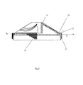
Fig.1 is a side-view of rotor in collection with a shaft in a section. -
Fig.2 is an above-view of the first basic and first butt end wall of the housing from above. -
Fig.3 is a side-view of overhead element of the housing in a cut section. -
Fig.4 is a view of separate area B on the surface of the first basic and first butt end walls of the housing onFig.2 in the expanded scale. -
Fig.5 is a view of separate area B onFig.3 in the expanded scale. -
Fig.6 is a cut by the line of G-G onFig.4 in the expanded scale. -
Fig.7 is a cut by the line of A-A onFig.3 in the expanded scale. -
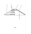
Fig.8 is a side-view of cap. -
Fig.9 is an above-view of cap. -
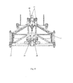
Fig.10 is a general view of heat-generator for heating of liquid in a cut section. - On
figures 1-9 , as an example, the one of possible variants of implementation of rotor of heat-generator for heating of liquid is shown and the possible variants of implementation of separate elements of rotor are given. -
Rotor 1 of heat-generator for heating of liquid (Fig. 1 ) consists of the housing 2 and thecap 3. The housing contains the three basic walls - the first basic wall 4, the secondbasic wall 5 and the thirdbasic wall 6. The first and second basic walls of the housing are opposite. The third basic wall of the housing is located between the first and second basic walls of the housing. - The first and second basic walls of the housing are made with
external surfaces 7 and 8 in form of a truncated cone and with identical direction of tapering of external surfaces of the walls. The thirdbasic wall 6 of the housing is made with anexternal surface 9 of cylinder form. The second and third basic walls of the housing simultaneously are the second and third walls of the rotor, and the external surfaces of the second and third basic walls of the housing are the external surfaces of the second and third walls of rotor. - On the
external surface 7 of the first basic wall of the housing thefirst grooves 10 are made for a liquid passage-ways which pass from one edge to other edge of external surface of the first basic wall of the housing. - A cap 3 (
Fig. 1 ,8 ) is made as a hollow cone with onelateral wall 11, in which theaxial opening 12 is made. External andinternal surfaces cap 3 is connected with the housing so that theinternal surface 14 of the wall of cap adjoins to theexternal surface 7 of the first basic wall of the housing of rotor. - Thus the internal surface of the wall of cap covers the opened parts of the
first grooves 10 on the external surface of the first basic wall of the cap with formation of internal channels in the rotor. - An
axial channel 15 is made for ashaft 30 in the housing. Theshaft 30 is made in such way which executes the functions of turbulence promoter and distributor of stream of liquid and through it a liquid passes in the internal channels of the first wall of rotor. - Presence of internal channels in the rotor, through which the stream of liquid passes, leads at the rotation of rotor (due to influence on the streams of liquid of centrifugal force) to the acceleration of streams of liquid, which speeds up the streams of liquid and increases the degree of turbulence of streams of liquid, implementation of the first basic wall of the housing of rotor in form of a truncated cone allows to increase length of internal channels in the rotor, and accordingly additionally to speeds up the streams of liquid and increases the degree of turbulence of streams of liquid.
- For simplification of making of the housing it can consist of
overhead element 16 andlower element 17 that are united between them. For simplification of explanation of possible variants of implementation of separate elements of the housing onFig.3 the view of overhead element is shown. - As a variant, the housing can contain additionally the first and second
butt end walls 18 and 19 (Fig. 1 ). The firstbutt end wall 18 of the housing is located between the first 4 and third 6 basic walls of the housing. Theexternal surface 20 of the firstbutt end wall 18 of the housing is made in form of a ring. The secondbutt end wall 19 is located between the third 6 and second 5 basic walls of the housing. Theexternal surface 21 of the secondbutt end wall 19 of the housing is made in form of a ring. - On the external surface of the first butt end wall of the housing the row of the second
blind openings 22 and the second grooves 23 (Fig. 2 ,4 ) can be made, and the second blind openings are made so that the longitudinal axes of all of the second blind openings are located on identical distance from the conditionallongitudinal axis 24 of the rotor, and the second grooves are made so that through every blind opening one groove passes and longitudinal axes of grooves are located under an identical corner in relation to conditional radial lines, conducted from axes of the blind openings to the conditional longitudinal 24 axis of the rotor. - On the
external surface 21 of the second butt end wall of the housing the row of the sixthblind openings 25 can be made (Fig. 1 ), which is made alike to the row of the secondblind openings 22 of the external surface of the firstbutt end wall 18. - On the
external surface 7 of the first basic wall of the housing in the place of transition between the first basic and first butt end walls of the housing the firstcircular groove 26 can be made (Fig. 2 ,3 ,4 ,5 ). The circular groove forms on the external surface of the first basic wall of the housing thesurface 27 of a cylinder form, on which thecoulisses 28 of semi-cylinder form are made with an even interval (Fig. 2 ,4 ,5 ). - In addition, on the
external surface 7 of the first basic wall of the housing a few rows of the firstblind openings 29 can be made (Fig. 2 ). The rows of the first blind openings are made so that in every row the first blind openings are spatially located on identical and certain distance from the conditionallongitudinal axis 24 of rotor for every row, every row of theblind openings 29 from the second to the last one contains the identical amount of the blind openings, the first row of theblind openings 29 contains blind openings twice more than the second row of the blind openings and amount ofcoulisses 28 equals the amount of the blind openings in the first row of the firstblind openings 29. - In addition, the first grooves on the
external surface 7 of the first basic wall of the housing can be made as spiral grooves (Fig. 2 ).First grooves 10 are made so that their amount equals the amount of the blind openings in the second row of the firstblind openings 29 and each offirst grooves 10 passes from the edge ofexternal surface 7 of the first basic wall of the housing consistently through one blind opening in every row of the firstblind openings 29 and ends near thecoulisse 28. Implementation ofgrooves 10 as spirals accordingly results in formation of internal channels of spiral form in the rotor. It increases the speed of streams of liquid on an exit from internal channels and increases the degree of turbulence of the stream of the liquid. - In addition, on the external surface of the first wall of the housing the
additional grooves 31 can be made (Fig. 2 ).Additional grooves 31 are made so that every additional groove passes consistently through one blind opening of the second and first rows of the firstblind openings 29 and ends near thecoulisse 28 of a semi-cylinder form, hereadditional grooves 31 pass through such blind openings in the first row of the firstblind openings 29 andcoulisse 28, through which thefirst grooves 10 do not pass and near which they are not ended. - In addition, on the
external surface 9 of the third basic wall of the housing a few rows of the thirdblind openings 32, thethird grooves 33 and secondcircular grooves 34 can be made (Fig. 3 ,7 ). All the rows of the thirdblind openings 32 have an identical amount of the blind openings, and the blind openings in every row are located so that axes of the blind openings are in the plane of conditional circle at the identical distance to each other and are displaced in relation to the axes of the thirdblind openings 32 in nearby rows at a certain step. Thethird grooves 33 are made so that the amount of grooves equals the amount of the blind openings in the row of the thirdblind openings 32 and each of thethird grooves 33 passes from one to other edge ofexternal surface 9 of the third basic wall of the housing consistently through one blind opening in every row of the thirdblind openings 32. The secondcircular grooves 34 are made so that they are located between the rows of the thirdblind openings 32. - In addition, on an
external surface 13 the walls of cap a few rows of the fourthblind openings 35 can be made (Fig. 8 ,9 ). In every row the fourthblind openings 35 are spatially located on identical and certain distance from the conditionallongitudinal axis 24 of rotor for every row. - In addition, on the external surface 8 of the second basic wall of the housing a few rows of the fifth
blind openings 36 are made (Fig. 1 ), they are made like the rows of the fourthblind openings 35 on theexternal surface 13 of wall of cap. - The presence of the blind openings and grooves on the external surfaces of walls of rotor considerably increases the area of surface of rotor, with which the stream of liquid contacts and the degree of turbulence of stream of liquid which results in the increase of efficiency of transformation of kinetic energy of motion of stream of liquid in thermal energy and increase of temperature of heating of liquid.
- The example of work of rotor of heat-generator is shown on
Fig. 10 , where the general view of heat-generator is represented. Therotor 1 is located in thestator 37, the internal surfaces of walls of which are conjugated with a gap with the external surfaces of the walls of the rotor. An engine (it is not shown) drives theshaft 30 of heat-generator androtor 1 of heat-generator into the rotation. Liquid, for example, water, is driven by a pump to the entrance of thebranch pipe 38 for a liquid. Passing through the entrance branch pipe, the flow of liquid gets in theaxial channel 39 of the shaft. Then the general stream of liquid is distributed into a few even streams and passes throughradial channels 40 in the housing of the shaft, whereupon streams get ininternal channels 41 of the rotor. In internal channels the streams of liquid move in direction from the axis of the shaft rotation. As a result of the rotation of rotor the streams of liquid ininternal channels 41 get an additional centrifugal acceleration and due to it there is an increase of speed of streams of liquid and the degree of turbulence of streams of liquid rises. - Afterwards the internal channels of rotor the streams of liquid go out on the external surface of the first wall of rotor and get in a gap between the external surfaces of wall of rotor and internal surface of wall of stator, where on the walls of the stator there is slowing down of part of the stream of liquid and the liquid is heated. The heated liquid goes out from the heat-generator through a channel 42 in the wall of stator.
- The given examples only illustrate the invention but they do not limit it.
Claims (8)
- Rotor of heat-generator for heating of liquid, which contains a housing which three basic walls, the first and second basic walls of the housing of the rotor are opposite and the third wall of the housing of rotor is located between the first and second basic walls of the housing of rotor, there is an axial channel in the rotor for a shaft, characterized in that the rotor (1) contains additionally a cap (3), the first and second basic walls (4,5) of the housing (2) are executed with the external surfaces (7,8) of the walls in form of a truncated cone and with the identical direction of tapering of external surfaces of the walls, the third basic wall (6) of housing (2) is executed with the external surface (9) of cylinder form, on the external surface (7) of the first basic wall (4) of the housing the first grooves (10) are executed for a passage-way for liquid, and the first grooves (10) are executed so, that pass from one edge to other of external surface (7) of the first basic wall (4) of the housing, the cap (3) is executed as a hollow cone with one lateral wall (11) in which the axial opening (12) is made, the external surface (13) and internal one (14) of the wall of cap (3) are executed in form of a truncated cone, and the cap (3) is connected with the housing (2) so that the internal surface (14) of the wall of cap (3) adjoins the external surface (7) of the first basic wall (4) of the housing (2).
- Rotor of heat-generator for heating of liquid according to claim 1, characterized in that the housing (2) contains additionally the first butt end wall (18) which is located between the first (4) and third (6) basic walls of the housing (2), and the external surface of the first butt end wall (20) of the housing is executed in form of a ring, the housing (2) contains additionally the second butt end wall (19) which is located between the third (6) and second (5) basic walls of the housing, and the external surface of the second butt end wall (21) of the housing is executed in form of a ring, on the external surface (7) of the first basic wall (4) of the housing in the place of transition between the first basic wall (4) and the first butt end wall (18) of the housing the first circular groove (26) is executed, which forms on the external surface (7) of the first basic wall (4) of the housing (2) the surface of a cylinder form (27) on which the coulisses (28) of semi-cylinder form are executed with an even interval, on the external surface (7) of the first basic wall (4) of the housing a few rows of the first blind openings (29) are executed so that in every row the first blind openings (29) are spatially located on identical and certain distance from the conditional longitudinal axis (24) of rotor (1) for every row, thus every row of the first blind openings (29) from the second to the last one contains the identical amount of the first blind openings (29) and the first row of the first blind openings (29) contains twice more blind openings than the second row of the first blind openings (29) on the external surface (7) of the first basic wall (4) of the housing, the first grooves (10) are executed as spiral grooves so that their amount equals the amount of the first blind openings (29) in the second row of the blind openings and each of the first grooves (10) passes from the edge of external surface (7) of the first basic wall (4) of the housing consistently through one first blind opening (29) in every row of the first blind openings (29) and finishes near the coulisse (28) of semi-cylinder form.
- Rotor of heat-generator for heating of liquid according to claim 2, characterized in that on the external surface (7) of the first wall (4) of the housing (2) the additional grooves (31) are executed, thus every additional groove (31) passes consistently through one blind opening of the second and first rows of the first blind openings (29) and finishes near the coulisse (28) of a semi-cylinder form, and the additional grooves (31) pass through such blind openings in the first row of the first blind openings (29) and finish near such coulisses (28) of a semi-cylinder form, through which the first grooves (10) do not pass and near which they do not end.
- Rotor of heat-generator for heating of liquid according to any claims 2-3, characterized in that on the external surface of the first butt end wall (20) of the housing the row of the second blind openings (22) and of the second grooves (23) is executed, thus the second blind openings (22) are executed so that the longitudinal axes of all of the blind openings are located on identical distance from the conditional longitudinal axis (24) of rotor (1), the second grooves (23) are made so that one groove and longitudinal axes of grooves passes through every second blind opening and is located under an identical corner in relation to conditional radial lines, conducted from axes of the second blind openings (22) to the conditional longitudinal axis (24) of the rotor (1).
- Rotor of heat-generator for heating of liquid according to any claims 1-4, characterized in that on the external surface (9) of the third basic wall (6) of the housing (2) a few rows of the third blind openings (32), the third grooves (33) and the second circular grooves (34) are executed, all of rows of the third blind openings (32) have an identical amount of the blind openings, and the third blind openings (32) in every row are located so that axes of the third blind openings (32) are in the plane of conditional circle at identical distance to each other and displaced in relation to the axes of the third blind openings (32) in nearby rows at a certain step, the third grooves (33) are executed so that the amount of grooves equals the amount of the blind openings in the row of the third blind openings (32) and each of the third grooves (33) passes from one to other edge of external surface (9) of the third basic wall (6) of the housing (2) consistently through one blind opening in every row of the third blind openings (32), the second circular grooves (34) are located between the rows of the third blind openings (32).
- Rotor of heat-generator for heating of liquid according to any claims 1-5, characterized in that on the external surface (13) of the wall of cap (3) a few rows of the fourth blind openings (35) are executed so that in every row the fourth blind openings (35) are spatially located on identical and certain distance for every row from the conditional longitudinal axis (24) of the rotor (1).
- Rotor of heat-generator for heating of liquid according to any claims 2-6, characterized in that on the external surface (8) of the second basic wall (5) of the housing (2) a few rows of the fifth blind openings (36) are executed so that in every row the fifth blind openings (36) are spatially located on identical and certain distance from the conditional longitudinal axis (24) of rotor (1) for every row.
- Rotor of heat-generator for heating of liquid according to any claims 3-7, characterized in that on the external surface of the second butt end wall (21) of the housing the row of the sixth blind openings (25) is executed, and the sixth blind openings (25) are executed so that the longitudinal axes of all of the sixth blind openings (25) are located on identical distance from the conditional longitudinal axis (24) of the rotor (1).
Priority Applications (1)
| Application Number | Priority Date | Filing Date | Title |
|---|---|---|---|
| EP08475006A EP2119981A1 (en) | 2008-05-13 | 2008-05-13 | Rotor of heat-generator for heating of liquid |
Applications Claiming Priority (1)
| Application Number | Priority Date | Filing Date | Title |
|---|---|---|---|
| EP08475006A EP2119981A1 (en) | 2008-05-13 | 2008-05-13 | Rotor of heat-generator for heating of liquid |
Publications (1)
| Publication Number | Publication Date |
|---|---|
| EP2119981A1 true EP2119981A1 (en) | 2009-11-18 |
Family
ID=39793770
Family Applications (1)
| Application Number | Title | Priority Date | Filing Date |
|---|---|---|---|
| EP08475006A Withdrawn EP2119981A1 (en) | 2008-05-13 | 2008-05-13 | Rotor of heat-generator for heating of liquid |
Country Status (1)
| Country | Link |
|---|---|
| EP (1) | EP2119981A1 (en) |
Cited By (1)
| Publication number | Priority date | Publication date | Assignee | Title |
|---|---|---|---|---|
| RU2624687C1 (en) * | 2016-04-21 | 2017-07-05 | Михаил Федорович Манаенков | Device for producing thermal energy |
Citations (4)
| Publication number | Priority date | Publication date | Assignee | Title |
|---|---|---|---|---|
| US3791349A (en) | 1973-01-29 | 1974-02-12 | Sonaqua Inc | Steam generator |
| DE10222947A1 (en) * | 2002-05-24 | 2003-12-04 | Behr Gmbh & Co | Heating device for motor vehicles |
| US6959669B2 (en) * | 2002-12-03 | 2005-11-01 | Christian Helmut Thoma | Apparatus for heating fluids |
| US20080060588A1 (en) * | 2004-07-28 | 2008-03-13 | Cristian Isopo | Centrifugal Rotary Device For Heating And/Or Vaporizing Liquids |
-
2008
- 2008-05-13 EP EP08475006A patent/EP2119981A1/en not_active Withdrawn
Patent Citations (4)
| Publication number | Priority date | Publication date | Assignee | Title |
|---|---|---|---|---|
| US3791349A (en) | 1973-01-29 | 1974-02-12 | Sonaqua Inc | Steam generator |
| DE10222947A1 (en) * | 2002-05-24 | 2003-12-04 | Behr Gmbh & Co | Heating device for motor vehicles |
| US6959669B2 (en) * | 2002-12-03 | 2005-11-01 | Christian Helmut Thoma | Apparatus for heating fluids |
| US20080060588A1 (en) * | 2004-07-28 | 2008-03-13 | Cristian Isopo | Centrifugal Rotary Device For Heating And/Or Vaporizing Liquids |
Cited By (1)
| Publication number | Priority date | Publication date | Assignee | Title |
|---|---|---|---|---|
| RU2624687C1 (en) * | 2016-04-21 | 2017-07-05 | Михаил Федорович Манаенков | Device for producing thermal energy |
Similar Documents
| Publication | Publication Date | Title |
|---|---|---|
| US9080451B2 (en) | Airfoil | |
| KR100905963B1 (en) | Reaction Steam Turbine | |
| KR19990063333A (en) | Method and apparatus for sealing a separation gap formed between the rotor and the stator in a non-contact manner | |
| US20110097189A1 (en) | Boundary layer effect turbine | |
| CN101846320A (en) | Vortex generator, method for avoiding flame recoil in a burner and burner | |
| RU2649159C2 (en) | Airfoil device and airfoil device assembly for a gas turbine | |
| EP2865850A1 (en) | Impingement cooling arrangement | |
| KR101052253B1 (en) | Reaction turbine | |
| CA2924922C (en) | Fluid delivery system for a gas turbine engine | |
| CN106460518A (en) | Axial fluid machine and method for power extraction | |
| US20160032730A1 (en) | Obtuse angle chevron trip strip | |
| EP2119981A1 (en) | Rotor of heat-generator for heating of liquid | |
| CN103114876B (en) | Impact type air turbine machine and wavy hair power plant | |
| US4390316A (en) | Turbine wheel | |
| RU2614946C2 (en) | Jet-reactive turbine | |
| EP2119980A1 (en) | Heat generator for heating of liquids | |
| US9810195B2 (en) | Turbine with radial inlet and outlet and multi-element guide vanes for oscillating flows | |
| EP2020570A2 (en) | Valveless pulse combustor | |
| KR101332613B1 (en) | Radial impeller combined multi-layer turbine | |
| US10301958B2 (en) | Gas turbine engine with seal having protrusions | |
| US10253642B2 (en) | Gas turbine engine with disk having periphery with protrusions | |
| US4529354A (en) | Total flow turbine | |
| US4519744A (en) | Turbine power plant | |
| EP3290650A1 (en) | Low-pressure steam turbine diffuser for reducing shock losses | |
| RU2302535C1 (en) | Turbine compartment |
Legal Events
| Date | Code | Title | Description |
|---|---|---|---|
| PUAI | Public reference made under article 153(3) epc to a published international application that has entered the european phase |
Free format text: ORIGINAL CODE: 0009012 |
|
| AK | Designated contracting states |
Kind code of ref document: A1 Designated state(s): AT BE BG CH CY CZ DE DK EE ES FI FR GB GR HR HU IE IS IT LI LT LU LV MC MT NL NO PL PT RO SE SI SK TR |
|
| AX | Request for extension of the european patent |
Extension state: AL BA MK RS |
|
| AKX | Designation fees paid | ||
| REG | Reference to a national code |
Ref country code: DE Ref legal event code: 8566 |
|
| STAA | Information on the status of an ep patent application or granted ep patent |
Free format text: STATUS: THE APPLICATION IS DEEMED TO BE WITHDRAWN |
|
| 18D | Application deemed to be withdrawn |
Effective date: 20100519 |