EP2119581A1 - Air diffusing or distributing device with synthetic jets - Google Patents
Air diffusing or distributing device with synthetic jets Download PDFInfo
- Publication number
- EP2119581A1 EP2119581A1 EP08425311A EP08425311A EP2119581A1 EP 2119581 A1 EP2119581 A1 EP 2119581A1 EP 08425311 A EP08425311 A EP 08425311A EP 08425311 A EP08425311 A EP 08425311A EP 2119581 A1 EP2119581 A1 EP 2119581A1
- Authority
- EP
- European Patent Office
- Prior art keywords
- main
- lateral
- duct
- air
- flow
- Prior art date
- Legal status (The legal status is an assumption and is not a legal conclusion. Google has not performed a legal analysis and makes no representation as to the accuracy of the status listed.)
- Granted
Links
Images


Classifications
-
- B—PERFORMING OPERATIONS; TRANSPORTING
- B60—VEHICLES IN GENERAL
- B60H—ARRANGEMENTS OF HEATING, COOLING, VENTILATING OR OTHER AIR-TREATING DEVICES SPECIALLY ADAPTED FOR PASSENGER OR GOODS SPACES OF VEHICLES
- B60H1/00—Heating, cooling or ventilating devices
- B60H1/34—Nozzles; Air-diffusers
- B60H1/3414—Nozzles; Air-diffusers with means for adjusting the air stream direction
-
- F—MECHANICAL ENGINEERING; LIGHTING; HEATING; WEAPONS; BLASTING
- F15—FLUID-PRESSURE ACTUATORS; HYDRAULICS OR PNEUMATICS IN GENERAL
- F15D—FLUID DYNAMICS, i.e. METHODS OR MEANS FOR INFLUENCING THE FLOW OF GASES OR LIQUIDS
- F15D1/00—Influencing flow of fluids
- F15D1/02—Influencing flow of fluids in pipes or conduits
- F15D1/06—Influencing flow of fluids in pipes or conduits by influencing the boundary layer
-
- F—MECHANICAL ENGINEERING; LIGHTING; HEATING; WEAPONS; BLASTING
- F15—FLUID-PRESSURE ACTUATORS; HYDRAULICS OR PNEUMATICS IN GENERAL
- F15D—FLUID DYNAMICS, i.e. METHODS OR MEANS FOR INFLUENCING THE FLOW OF GASES OR LIQUIDS
- F15D1/00—Influencing flow of fluids
- F15D1/14—Diverting flow into alternative channels
Definitions
- the present invention relates to air diffusing and distributing devices of the type comprising a main duct for a main air flow and means to deviate said main air flow toward any one of two or more outlet areas opening onto an external space or toward any one of two or more secondary ducts branching from the main duct.
- the present invention is for example applicable to an air outlet vent for the dashboard of an auto-vehicle, or to an air outlet vent for an air conditioning device in a building or again for example to an air distributing device in an air-conditioning plant of an auto-vehicle or of a vehicle in general (for example a railway vehicle or an aircraft).
- the applicant has already proposed and developed air distributing and diffusing devices that exploit the Coanda effect to direct a main air flow in the desired direction (see for example EP-A-1 399 324 , EP-A-1 399 686 , EP-A-1 382 472 , EP-A-1 585 642 , EP-A-1 544 004 , EP-A-1 544 005 , EP-A-1 544 006 , EP-A-1 544 007 ).
- This solution eliminates the need to provide for deflecting elements that influence the fluid-dynamic characteristics of the air flow, so that they represent a significant step forward in the development of such devices.
- the purpose of the present invention is to propose an alternative solution, that likewise possesses the advantage of not substantially influencing the characteristics of velocity and capacity of the main air flow, that is of general applicability, and that is also characterised on one hand by the simplicity of its construction and its reduced dimensions, and on the other hand by its reliability in operation.
- the invention has as its object an air diffusing or distributing device having the characteristics that were indicated at the beginning of the present description and also characterised in that said air deviating means comprises at least one synthetic jet generating device adjacent to a lateral wall of the main duct having an end portion with a curved profile diverging outwards in the direction of flow, said synthetic jet generating device being able to be activated to direct a series of synthetic jets within the main duct, in such a manner as to energise the boundary layer adjacent to said lateral wall, so as to cause the main air flow to adhere to said lateral wall and a consequent deviation of the air flow towards one of the said outlet areas that is situated on the extension of said lateral wall or towards one of said secondary ducts that extend on the extension of said lateral wall.
- jet is indicated a flow of fluid that is generated by effect of the mixing of a current of a fluid within a second fluid.
- Synthetic jets have been studied relatively recently and are typically obtained by predisposing a hollow body 1 (see figure 1 ) defining within it a chamber 2 delimited on one side by a flexible metal lamina 3 to which is associated a piezoelectric element 4 that is subject to a contraction following on to the supply of electric power.
- the chamber 2 communicates through an opening 5 to a space 6.
- the piezoelectric element 4 is supplied with electric power in a pulsating manner such as to subject the flexible membrane 3 to an alternating movement in the direction indicated by the arrow A, with predetermined frequency and amplitude.
- reference number 8 indicates diagrammatically an electronic control unit controlling the electric power supplied to the piezoelectric element 4.
- the present invention is based on the idea of applying a synthetic jet generating device of the type illustrated in figure 1 to an air diffusing and distributing device.
- the main advantage of the invention lies in the absence of fins or levers to deviate the air flow, with consequent elimination of the loss of energy connected with the presence of such elements.
- a further significant advantage of the invention lies in the fact that it can readily be applied in any field, and in particular in the automobile sector and in that of air-conditioning plants for buildings.
- a further significant advantage lies in the possibility of varying the synthetic jet generating device control logic at will and likewise the wave form of the command signal applied to it, such as to vary the frequency and/or amplitude of movement of the membrane 3, so as in consequence to vary the intensity of the synthetic jets 7. In this way it is possible to direct the airflow as preferred, and if desired also in a gradual and continuous manner, deviating the flow gradually from a first direction towards a second direction.
- reference number 9 indicates overall an air diffusing device associated with a vent 10 destined to be mounted on the dashboard of an auto-vehicle.
- the body of the diffusing device 9 comprises a main duct 11 through which an air of flow F moves and terminating in the vent 10, in correspondence with which for preference fins 12 are provided for, for example of the type orientable manually, to direct the flow vertically.
- the body of the main duct 11 presents an upper wall 13 and a lower wall (not visible in figure 2 ) opposed to one another and two lateral walls 14 that have an end portion in which they diverge from one another in the direction of an outlet vent 10, following a curved profile.
- Two devices 15 to generate synthetic jets are prearranged adjacent to the two lateral walls 14, before the divergent end portion 11a of the main duct 11.
- Figures 3 and 4 show the main duct 11 in section and one of the devices 15 to generate synthetic jets.
- Figure 3 illustrates the condition in which the device 15 is off, so that the main air flow F is substantially rectilinear.
- Figure 4 illustrates the deviation of the flow F that comes about when the synthetic jet generating device 15 is activated, with a predetermined frequency and amplitude.
- the emission of synthetic jets 7 into the flow F energises the boundary layer adjacent to the lateral wall 14, such that the flow F is encouraged to remain adherent to that wall, so as to be deviated toward a lateral zone of the outlet vent 10.
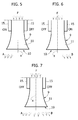
- Figures 5-7 show how, by activating and deactivating the two synthetic jet generating devices 15 associated to the two lateral walls 14, it is possible to control the direction of the air flow leaving the vent 10.
- the device 15 illustrated at the left is on, whereas the device 15 at the right is off.
- the flow F is in the main guided in the direction A, laterally inclined (toward the left with reference to the figure) with respect to the axis X of the device.
- Deactivating the device 15 on the left and activating that on the right ( figure 6 ) the flow is sent in the direction B inclined laterally toward the right (with reference to figure 6 ) with respect to the axis X.
- both devices are off ( figure 7 ) the prevalent part of the flow F leaves the vent 10 in the direction of the axis X, part of the flow being nevertheless also deviated in directions A and B.
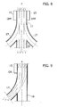
- Figures 8 and 9 illustrate two examples of the application of the device according to the invention to an air distributing device, that could for example be used in the field of an air-conditioning plant for an auto-vehicle.
- the main duct 11 flows into a plurality of secondary ducts that branch from it.
- a single lateral duct 17 is provided alongside the central duct 16.
- there are two synthetic jet generating devices 15 associated with the two sides of the main duct 11 whereas in the case of figure 9 there is a single generating device on the side of the duct 11 on which the secondary lateral duct 17 is situated.
- the electronic unit 8 that controls the electric power supply to the piezoelectric element 4 may vary the duty cycle of the pulsed power supply to the piezoelectric element, that is it may vary the relationship between the duration of each pulse and the period between each pulse and the next.
- the electronic unit 8 that controls the electric power supply to the piezoelectric element 4 may vary the duty cycle of the pulsed power supply to the piezoelectric element, that is it may vary the relationship between the duration of each pulse and the period between each pulse and the next.
- This characteristic may be exploited for example in the case of the outlet vent of an air conditioning device for a room in a building, so as to make the outflow oscillate continuously between one direction and the opposite one.
- the device according to the invention may easily be adapted to being used as an air diffusing device, to vary the direction in which an air flow leaves a vent, or also as an air distributing device in any conditioning plant for a vehicle or for civil engineering applications.
- the invention is characterised by extreme simplicity of construction, reduced dimensions and high reliability and flexibility of application.
- each synthetic jet generating device may also be different from a piezoelectric actuator, for example in particular it may consist of an electromagnetic actuator (for example of the "voice coil” type for the reproduction of sound) or of an electromechanical actuator, for example of the type comprising a piston activated by an electric motor.
- a piezoelectric actuator for example in particular it may consist of an electromagnetic actuator (for example of the "voice coil” type for the reproduction of sound) or of an electromechanical actuator, for example of the type comprising a piston activated by an electric motor.
Landscapes
- Engineering & Computer Science (AREA)
- Physics & Mathematics (AREA)
- Mechanical Engineering (AREA)
- Fluid Mechanics (AREA)
- General Engineering & Computer Science (AREA)
- Thermal Sciences (AREA)
- Air-Flow Control Members (AREA)
- Air-Conditioning For Vehicles (AREA)
- Duct Arrangements (AREA)
- Nozzles (AREA)
- Respiratory Apparatuses And Protective Means (AREA)
Abstract
Description
- The present invention relates to air diffusing and distributing devices of the type comprising a main duct for a main air flow and means to deviate said main air flow toward any one of two or more outlet areas opening onto an external space or toward any one of two or more secondary ducts branching from the main duct.
- The present invention is for example applicable to an air outlet vent for the dashboard of an auto-vehicle, or to an air outlet vent for an air conditioning device in a building or again for example to an air distributing device in an air-conditioning plant of an auto-vehicle or of a vehicle in general (for example a railway vehicle or an aircraft).
- In the case of known air diffusing devices, for example in the case of air outlet vents on the dashboard of an auto-vehicle, the most traditional manner to give the air flow leaving the outlet a preferred direction is that of providing the vent with a plurality of orientable fins, with manual or electrical control. The drawback of this solution is that it involves an interference of the directional fins with the air flow with consequent loss of energy by said flow. What is indicated above applies in an identical manner also to the case of air distributing devices of known type, which traditionally include deflector elements to deviate the air flow in the desired direction, that involves penalising the characteristics (velocity and capacity) of the air flow.
- The applicant has already proposed and developed air distributing and diffusing devices that exploit the Coanda effect to direct a main air flow in the desired direction (see for example
EP-A-1 399 324 ,EP-A-1 399 686 ,EP-A-1 382 472 ,EP-A-1 585 642 ,EP-A-1 544 004 ,EP-A-1 544 005 ,EP-A-1 544 006 ,EP-A-1 544 007 ). This solution eliminates the need to provide for deflecting elements that influence the fluid-dynamic characteristics of the air flow, so that they represent a significant step forward in the development of such devices. - The purpose of the present invention is to propose an alternative solution, that likewise possesses the advantage of not substantially influencing the characteristics of velocity and capacity of the main air flow, that is of general applicability, and that is also characterised on one hand by the simplicity of its construction and its reduced dimensions, and on the other hand by its reliability in operation.
- In view of achieving this purpose, the invention has as its object an air diffusing or distributing device having the characteristics that were indicated at the beginning of the present description and also characterised in that said air deviating means comprises at least one synthetic jet generating device adjacent to a lateral wall of the main duct having an end portion with a curved profile diverging outwards in the direction of flow, said synthetic jet generating device being able to be activated to direct a series of synthetic jets within the main duct, in such a manner as to energise the boundary layer adjacent to said lateral wall, so as to cause the main air flow to adhere to said lateral wall and a consequent deviation of the air flow towards one of the said outlet areas that is situated on the extension of said lateral wall or towards one of said secondary ducts that extend on the extension of said lateral wall.
- The use of "synthetic jets" (or "synjets") has already been proposed in the aeronautics field (
US 6 471 477 B2 ), as well as in a patent held by the applicant relating to an application of such jets to an auto-vehicle (seeEP-A-1 544 089 ). - In general, by "jet" is indicated a flow of fluid that is generated by effect of the mixing of a current of a fluid within a second fluid. "Synthetic jets" have been studied relatively recently and are typically obtained by predisposing a hollow body 1 (see
figure 1 ) defining within it achamber 2 delimited on one side by aflexible metal lamina 3 to which is associated a piezoelectric element 4 that is subject to a contraction following on to the supply of electric power. On the opposite side, thechamber 2 communicates through anopening 5 to a space 6. The piezoelectric element 4 is supplied with electric power in a pulsating manner such as to subject theflexible membrane 3 to an alternating movement in the direction indicated by the arrow A, with predetermined frequency and amplitude. Said phenomenon does not involve the injection of an additional mass of air into the space 6, since the flows of air entering and leaving through theopening 5 are substantially equivalent. However, the flows exiting generate trains ofvortices 7 disposed ring-wise around the axis of the opening 5. Infigure 1 ,reference number 8 indicates diagrammatically an electronic control unit controlling the electric power supplied to the piezoelectric element 4. - The present invention is based on the idea of applying a synthetic jet generating device of the type illustrated in
figure 1 to an air diffusing and distributing device. - The main advantage of the invention lies in the absence of fins or levers to deviate the air flow, with consequent elimination of the loss of energy connected with the presence of such elements. A further significant advantage of the invention lies in the fact that it can readily be applied in any field, and in particular in the automobile sector and in that of air-conditioning plants for buildings. A further significant advantage lies in the possibility of varying the synthetic jet generating device control logic at will and likewise the wave form of the command signal applied to it, such as to vary the frequency and/or amplitude of movement of the
membrane 3, so as in consequence to vary the intensity of thesynthetic jets 7. In this way it is possible to direct the airflow as preferred, and if desired also in a gradual and continuous manner, deviating the flow gradually from a first direction towards a second direction. - Further characteristics and advantages of the invention will be clear in the following description with reference to the attached drawings, provided as a simple non-limiting example, in which:
-
figure 1 is a diagrammatic section view of a synthetic jet generating device usable in the device according to the invention, -
figure 2 is a diagrammatic prospective view of a first embodiment of the device according to the invention, -
figures 3 and 4 are partial section views at enlarged scale of a detail of the device infigure 2 , in two different operating conditions, -
figures 5-7 are plan views illustrating three different operating conditions of the device infigure 2 , and -
figures 8 and 9 are diagrammatic plan views illustrating two further embodiments of the device according to the invention. - In
figure 2 ,reference number 9 indicates overall an air diffusing device associated with avent 10 destined to be mounted on the dashboard of an auto-vehicle. The body of the diffusingdevice 9 comprises amain duct 11 through which an air of flow F moves and terminating in thevent 10, in correspondence with which forpreference fins 12 are provided for, for example of the type orientable manually, to direct the flow vertically. The body of themain duct 11 presents anupper wall 13 and a lower wall (not visible infigure 2 ) opposed to one another and twolateral walls 14 that have an end portion in which they diverge from one another in the direction of anoutlet vent 10, following a curved profile. - Two
devices 15 to generate synthetic jets, each fundamentally of the type illustrated infigure 1 , are prearranged adjacent to the twolateral walls 14, before thedivergent end portion 11a of themain duct 11. -
Figures 3 and 4 show themain duct 11 in section and one of thedevices 15 to generate synthetic jets.Figure 3 illustrates the condition in which thedevice 15 is off, so that the main air flow F is substantially rectilinear.Figure 4 illustrates the deviation of the flow F that comes about when the syntheticjet generating device 15 is activated, with a predetermined frequency and amplitude. The emission ofsynthetic jets 7 into the flow F energises the boundary layer adjacent to thelateral wall 14, such that the flow F is encouraged to remain adherent to that wall, so as to be deviated toward a lateral zone of theoutlet vent 10. -
Figures 5-7 show how, by activating and deactivating the two syntheticjet generating devices 15 associated to the twolateral walls 14, it is possible to control the direction of the air flow leaving thevent 10. In the case offigure 5 , thedevice 15 illustrated at the left is on, whereas thedevice 15 at the right is off. In this condition, the flow F is in the main guided in the direction A, laterally inclined (toward the left with reference to the figure) with respect to the axis X of the device. Deactivating thedevice 15 on the left and activating that on the right (figure 6 ) the flow is sent in the direction B inclined laterally toward the right (with reference tofigure 6 ) with respect to the axis X. When both devices are off (figure 7 ) the prevalent part of the flow F leaves thevent 10 in the direction of the axis X, part of the flow being nevertheless also deviated in directions A and B. -
Figures 8 and 9 illustrate two examples of the application of the device according to the invention to an air distributing device, that could for example be used in the field of an air-conditioning plant for an auto-vehicle. In both cases, themain duct 11 flows into a plurality of secondary ducts that branch from it. In the case offigure 8 , twolateral ducts 17, opposed to one another, branch from thecentral duct 16. In the case offigure 9 , a singlelateral duct 17 is provided alongside thecentral duct 16. In the case offigure 8 , there are two syntheticjet generating devices 15 associated with the two sides of themain duct 11, whereas in the case offigure 9 there is a single generating device on the side of theduct 11 on which the secondarylateral duct 17 is situated. In the case of the embodiment infigure 8 , when both generatingdevices 15 are off, most of the flow F is conveyed into the centralsecondary duct 16. Activation of one or other of the twodevices 15 on the contrary causes the flow F to be deviated into one or other of the lateralsecondary ducts 17. Similarly, in the case offigure 9 , when thedevice 15 is off, the main flow F is conveyed for the most part into thesecondary duct 16, whereas when thedevice 15 is on, it causes most of the flow F to be deviated into thelateral duct 17. - A significant possibility offered by the device according to the invention lies in the fact that the
electronic unit 8 that controls the electric power supply to the piezoelectric element 4 may vary the duty cycle of the pulsed power supply to the piezoelectric element, that is it may vary the relationship between the duration of each pulse and the period between each pulse and the next. In this way, in the case for example of the embodiment illustrated infigures 2 and5-7 , it is possible to increase the degree of activation of one of the two synthetic jet generatingdevices 15 in a continuous manner, and at the same time to decrease the degree of activation of the other generatingdevice 15 in a continuous manner, in such a way that the flow leaving thevent 10 may be deviated continuously from direction A to direction B. This characteristic may be exploited for example in the case of the outlet vent of an air conditioning device for a room in a building, so as to make the outflow oscillate continuously between one direction and the opposite one. - As will be clear from the above description, the device according to the invention may easily be adapted to being used as an air diffusing device, to vary the direction in which an air flow leaves a vent, or also as an air distributing device in any conditioning plant for a vehicle or for civil engineering applications. The invention is characterised by extreme simplicity of construction, reduced dimensions and high reliability and flexibility of application.
- Naturally, the main of the invention holding good, construction details and embodiments may be widely varied with regard to what is described and illustrated here as a simple example, without thereby departing from the sphere of the present invention.
- For example, the actuating element provided in each synthetic jet generating device may also be different from a piezoelectric actuator, for example in particular it may consist of an electromagnetic actuator (for example of the "voice coil" type for the reproduction of sound) or of an electromechanical actuator, for example of the type comprising a piston activated by an electric motor.
Claims (9)
- Air diffusing or distributing device comprising a main duct (11) for a main air flow (F) and means to deviate said main air flow towards one or more outlet areas (A, X, B) opening onto an outside space or towards any one of two or more secondary ducts (16, 17) branching from the main duct,
characterised in that said air deviating means comprise a least one device (15) generating synthetic jets adjacent to a lateral wall (14) of the main duct (11) having an end portion with a curved profile diverging outwards in the direction of flow, said synthetic jet generating device being able to be activated to direct within the main duct (11) a series of synthetic jets (7) in such a manner as to energise the boundary layer adjacent to said lateral wall (14), such as to cause adherence of the main air flow (F) to said lateral wall (14) and a consequent deviation of the air flow toward one of said outlet areas (A, B) situated on the extension of said lateral wall (14) or towards one or more of said secondary ducts (17) situated on the extension of said lateral wall (14). - Device according to claim 1, characterised in that said air deviating means comprise two synthetic jet generators (15) situated adjacent to two opposed lateral walls (14) of the main duct (11).
- Device according to claim 1, characterised in that said means of deviation comprises a single synthetic jet generating device (15) situated adjacent to said lateral wall (14).
- Device according to claim 2, characterised in that three outlet areas are provided for (A, X, B) including a central outlet area (X) and two lateral outlet areas (A, B) or three secondary ducts (17, 16, 17), comprising a central secondary duct (16) and two lateral secondary ducts (17) and in that the two synthetic jet generating devices (15) are disposed such as when only one of them is on the main air flow (F) is deviated towards a respective lateral outlet area (A, B) or towards a respective lateral duct (17), whereas when both of the generating devices (15) are off, the main flow (F) is prevalently directed to the central outlet area (X) or into the central secondary duct (16) and in part also into the lateral outlet areas (A, B) or into the lateral secondary ducts (17).
- Device according to claim 1, characterised in that means (8) are associated to the or to each synthetic jet generating device (15) to vary the intensity of said synthetic jets (7).
- Device according to claim 5, characterised in that each synthetic jet generating device comprises a body (1) defining a cavity (2) communicating through an opening (5) with a passage for said main flow (F) within said main duct (11), said cavity (2) being delimited on one side by a mobile wall (3) to which is associated an electrically-activated actuator element (4) and means (8) to control pulsed electric power supplied to said piezoelectric actuator element (4) in such a manner as to generate an alternating movement of said mobile wall (3) with predetermined frequency and amplitude, so as to generate said synthetic jets (7).
- Device according to claim 6, characterised in that said actuator element is a piezoelectric actuator, or an electromagnetic actuator for example of the "voice coil" type used for the reproduction of sound, or an electromechanical actuator for example of the type comprising a piston moved by an electric motor.
- Device according to claim 1, characterised in that it is in the form of an air outlet vent assembly having a body defining said main duct (11) terminating with a vent (10) said main duct (11) having two lateral walls (14) that diverge from one another in the direction of said vent (10).
- Device according to claim 8, characterised in that it is predisposed to be assembled on the dashboard of an auto-vehicle.
Priority Applications (3)
| Application Number | Priority Date | Filing Date | Title |
|---|---|---|---|
| EP08425311A EP2119581B1 (en) | 2008-05-06 | 2008-05-06 | Air diffusing or distributing device with synthetic jets |
| DE602008002412T DE602008002412D1 (en) | 2008-05-06 | 2008-05-06 | Air diffuser or distributor with synthetic nozzles |
| AT08425311T ATE479567T1 (en) | 2008-05-06 | 2008-05-06 | AIR DIFFUSER OR DISTRIBUTOR WITH SYNTHETIC NOZZLES |
Applications Claiming Priority (1)
| Application Number | Priority Date | Filing Date | Title |
|---|---|---|---|
| EP08425311A EP2119581B1 (en) | 2008-05-06 | 2008-05-06 | Air diffusing or distributing device with synthetic jets |
Publications (2)
| Publication Number | Publication Date |
|---|---|
| EP2119581A1 true EP2119581A1 (en) | 2009-11-18 |
| EP2119581B1 EP2119581B1 (en) | 2010-09-01 |
Family
ID=39768815
Family Applications (1)
| Application Number | Title | Priority Date | Filing Date |
|---|---|---|---|
| EP08425311A Not-in-force EP2119581B1 (en) | 2008-05-06 | 2008-05-06 | Air diffusing or distributing device with synthetic jets |
Country Status (3)
| Country | Link |
|---|---|
| EP (1) | EP2119581B1 (en) |
| AT (1) | ATE479567T1 (en) |
| DE (1) | DE602008002412D1 (en) |
Cited By (3)
| Publication number | Priority date | Publication date | Assignee | Title |
|---|---|---|---|---|
| JP2015055394A (en) * | 2013-09-11 | 2015-03-23 | 三菱重工業株式会社 | Air conditioner having airflow control function |
| WO2015052012A1 (en) * | 2013-10-09 | 2015-04-16 | Dr. Schneider Kunststoffwerke Gmbh | Air vent |
| CN113740487A (en) * | 2020-05-29 | 2021-12-03 | 华为技术有限公司 | Fluid driver, fluid detection module and electronic equipment |
Families Citing this family (2)
| Publication number | Priority date | Publication date | Assignee | Title |
|---|---|---|---|---|
| DE102012012448B4 (en) | 2012-06-25 | 2022-02-03 | Volkswagen Aktiengesellschaft | Air flow generating device, use of such and motor vehicle |
| GB2536214B (en) * | 2015-03-05 | 2020-05-27 | Elogab O | Engine system and method of generating electricity from an internal combustion engine |
Citations (11)
| Publication number | Priority date | Publication date | Assignee | Title |
|---|---|---|---|---|
| EP1382472A1 (en) | 2002-07-16 | 2004-01-21 | C.R.F. Società Consortile per Azioni | An air-distribution device for motor vehicles |
| EP1399686A1 (en) | 2001-06-27 | 2004-03-24 | C.R.F. Società Consortile per Azioni | Fluid distribution device having improved deviating means |
| EP1399324A1 (en) | 2001-06-27 | 2004-03-24 | C.R.F. Società Consortile per Azioni | Air distribution system for a motor vehicle |
| WO2005008348A2 (en) * | 2003-07-07 | 2005-01-27 | Georgia Tech Research Corporation | System and method for thermal management using distributed synthetic jet actuators |
| EP1544004A1 (en) | 2003-12-16 | 2005-06-22 | C.R.F. Società Consortile per Azioni | System for distributing air to a row of seats in the passenger compartment of a means of transport or inside the room of a building |
| EP1544005A1 (en) | 2003-12-16 | 2005-06-22 | C.R.F. Società Consortile per Azioni | Air-distribution system for the dashboard of a motor vehicle and the dashboard of a motor vehicle comprising said system |
| EP1544089A1 (en) * | 2003-12-18 | 2005-06-22 | C.R.F. Società Consortile per Azioni | A motor vehicle with a device for controlling aerodynamic flow using synthetic jets |
| EP1544007A1 (en) | 2003-12-16 | 2005-06-22 | C.R.F. Società Consortile per Azioni | Air-distribution device based on the coanda effect |
| EP1544006A1 (en) | 2003-12-16 | 2005-06-22 | C.R.F. Società Consortile per Azioni | Air-distribution device based on the coanda effect with means for imparting a circulatory motion on the flow of air not properly oriented |
| EP1585642A1 (en) | 2003-01-24 | 2005-10-19 | C.R.F. Società Consortile per Azioni | A motor vehicle air conditioning system with an air distributor and mixer device, with coanda effect, having outlets at differentiated temperatures |
| FR2896758A1 (en) * | 2006-02-02 | 2007-08-03 | Renault Sas | MOTOR VEHICLE ASSEMBLY ADAPTED TO BE INTEGRATED IN A VEHICLE BODY MEMBER |
-
2008
- 2008-05-06 AT AT08425311T patent/ATE479567T1/en not_active IP Right Cessation
- 2008-05-06 EP EP08425311A patent/EP2119581B1/en not_active Not-in-force
- 2008-05-06 DE DE602008002412T patent/DE602008002412D1/en active Active
Patent Citations (11)
| Publication number | Priority date | Publication date | Assignee | Title |
|---|---|---|---|---|
| EP1399686A1 (en) | 2001-06-27 | 2004-03-24 | C.R.F. Società Consortile per Azioni | Fluid distribution device having improved deviating means |
| EP1399324A1 (en) | 2001-06-27 | 2004-03-24 | C.R.F. Società Consortile per Azioni | Air distribution system for a motor vehicle |
| EP1382472A1 (en) | 2002-07-16 | 2004-01-21 | C.R.F. Società Consortile per Azioni | An air-distribution device for motor vehicles |
| EP1585642A1 (en) | 2003-01-24 | 2005-10-19 | C.R.F. Società Consortile per Azioni | A motor vehicle air conditioning system with an air distributor and mixer device, with coanda effect, having outlets at differentiated temperatures |
| WO2005008348A2 (en) * | 2003-07-07 | 2005-01-27 | Georgia Tech Research Corporation | System and method for thermal management using distributed synthetic jet actuators |
| EP1544004A1 (en) | 2003-12-16 | 2005-06-22 | C.R.F. Società Consortile per Azioni | System for distributing air to a row of seats in the passenger compartment of a means of transport or inside the room of a building |
| EP1544005A1 (en) | 2003-12-16 | 2005-06-22 | C.R.F. Società Consortile per Azioni | Air-distribution system for the dashboard of a motor vehicle and the dashboard of a motor vehicle comprising said system |
| EP1544007A1 (en) | 2003-12-16 | 2005-06-22 | C.R.F. Società Consortile per Azioni | Air-distribution device based on the coanda effect |
| EP1544006A1 (en) | 2003-12-16 | 2005-06-22 | C.R.F. Società Consortile per Azioni | Air-distribution device based on the coanda effect with means for imparting a circulatory motion on the flow of air not properly oriented |
| EP1544089A1 (en) * | 2003-12-18 | 2005-06-22 | C.R.F. Società Consortile per Azioni | A motor vehicle with a device for controlling aerodynamic flow using synthetic jets |
| FR2896758A1 (en) * | 2006-02-02 | 2007-08-03 | Renault Sas | MOTOR VEHICLE ASSEMBLY ADAPTED TO BE INTEGRATED IN A VEHICLE BODY MEMBER |
Non-Patent Citations (2)
| Title |
|---|
| VÁCLAV TESA? ET AL.: "No-moving-part hybrid-synthetic jet actuator", SENSORS AND ACTUATORS A: PHYSICAL, vol. 125, no. 2, 10 January 2006 (2006-01-10), Elsevier B.V., pages 159 - 169, XP002499675 * |
| VACLAV TESAR ET AL.: "SENSORS AND ACTUATORS A: PHYSICAL", vol. 125, 10 January 2006, ELSEVIER B.V., article "No-moving part hybrid-synthetic jet actuator", pages: 159 - 169 |
Cited By (4)
| Publication number | Priority date | Publication date | Assignee | Title |
|---|---|---|---|---|
| JP2015055394A (en) * | 2013-09-11 | 2015-03-23 | 三菱重工業株式会社 | Air conditioner having airflow control function |
| WO2015052012A1 (en) * | 2013-10-09 | 2015-04-16 | Dr. Schneider Kunststoffwerke Gmbh | Air vent |
| CN105683673A (en) * | 2013-10-09 | 2016-06-15 | 施耐德博士塑料工厂有限公司 | Air vent |
| CN113740487A (en) * | 2020-05-29 | 2021-12-03 | 华为技术有限公司 | Fluid driver, fluid detection module and electronic equipment |
Also Published As
| Publication number | Publication date |
|---|---|
| DE602008002412D1 (en) | 2010-10-14 |
| ATE479567T1 (en) | 2010-09-15 |
| EP2119581B1 (en) | 2010-09-01 |
Similar Documents
| Publication | Publication Date | Title |
|---|---|---|
| EP2119581B1 (en) | Air diffusing or distributing device with synthetic jets | |
| US7815498B2 (en) | Device for distribution of air within the passenger compartment of a vehicle | |
| US8157532B2 (en) | Wind turbine blade with anti-noise devices | |
| US6722581B2 (en) | Synthetic jet actuators | |
| EP1544089B1 (en) | A motor vehicle with a device for controlling aerodynamic flow using synthetic jets | |
| CN101134504B (en) | Active systems and methods for controlling an airfoil vortex | |
| EP1627990A2 (en) | Boundary layer control arrangement | |
| US20100243819A1 (en) | Device for delaying boundary layer separation | |
| CN1675487A (en) | MEMS Pilot Valve | |
| EP1544004B1 (en) | System for distributing air to a row of seats in the passenger compartment of a means of transport or inside the room of a building | |
| AU2021372513A9 (en) | Dynamically controllable spray nozzle, control system, and method | |
| EP3539863A1 (en) | A leading edge structure for a flow control system of an aircraft | |
| CN115516201A (en) | Lift modifying device for a rotor blade, rotor blade of a wind turbine and method for modifying lift of a rotor blade | |
| EP3317547B1 (en) | Integral component with an active flow control device | |
| EP2628946A1 (en) | Aerodynamic blade and method of controlling the lift of such a blade | |
| CN100447432C (en) | Air distributor based on Coanda effect | |
| WO2022034327A1 (en) | A fan | |
| CN110963021B (en) | Flow guide body for an aircraft | |
| US11433955B2 (en) | Virtual air dam | |
| CN100489319C (en) | Air-distribution device based on the coanda effect with means for imparting a circulatory motion on the flow of air not properly oriented | |
| US7195555B2 (en) | Air duct outlets having return air passageways that facilitate oscillating air flow | |
| EP3895792B1 (en) | Oscillator for generating two or more pulsating fluid flows from a constant fluid flow and a method of generating fluid bubbles in a liquid | |
| US20050176362A1 (en) | Air duct outlets having self-oscillating air deflection members | |
| US6250586B1 (en) | Apparatus and method for controlling the motion of a solid body or fluid stream | |
| JPH053255Y2 (en) |
Legal Events
| Date | Code | Title | Description |
|---|---|---|---|
| PUAI | Public reference made under article 153(3) epc to a published international application that has entered the european phase |
Free format text: ORIGINAL CODE: 0009012 |
|
| 17P | Request for examination filed |
Effective date: 20090508 |
|
| AK | Designated contracting states |
Kind code of ref document: A1 Designated state(s): AT BE BG CH CY CZ DE DK EE ES FI FR GB GR HR HU IE IS IT LI LT LU LV MC MT NL NO PL PT RO SE SI SK TR |
|
| AX | Request for extension of the european patent |
Extension state: AL BA MK RS |
|
| GRAP | Despatch of communication of intention to grant a patent |
Free format text: ORIGINAL CODE: EPIDOSNIGR1 |
|
| AKX | Designation fees paid |
Designated state(s): AT BE BG CH CY CZ DE DK EE ES FI FR GB GR HR HU IE IS IT LI LT LU LV MC MT NL NO PL PT RO SE SI SK TR |
|
| GRAS | Grant fee paid |
Free format text: ORIGINAL CODE: EPIDOSNIGR3 |
|
| GRAA | (expected) grant |
Free format text: ORIGINAL CODE: 0009210 |
|
| AK | Designated contracting states |
Kind code of ref document: B1 Designated state(s): AT BE BG CH CY CZ DE DK EE ES FI FR GB GR HR HU IE IS IT LI LT LU LV MC MT NL NO PL PT RO SE SI SK TR |
|
| REG | Reference to a national code |
Ref country code: GB Ref legal event code: FG4D |
|
| REG | Reference to a national code |
Ref country code: CH Ref legal event code: EP |
|
| REG | Reference to a national code |
Ref country code: IE Ref legal event code: FG4D |
|
| REF | Corresponds to: |
Ref document number: 602008002412 Country of ref document: DE Date of ref document: 20101014 Kind code of ref document: P |
|
| REG | Reference to a national code |
Ref country code: NL Ref legal event code: VDEP Effective date: 20100901 |
|
| PG25 | Lapsed in a contracting state [announced via postgrant information from national office to epo] |
Ref country code: NO Free format text: LAPSE BECAUSE OF FAILURE TO SUBMIT A TRANSLATION OF THE DESCRIPTION OR TO PAY THE FEE WITHIN THE PRESCRIBED TIME-LIMIT Effective date: 20101201 Ref country code: LT Free format text: LAPSE BECAUSE OF FAILURE TO SUBMIT A TRANSLATION OF THE DESCRIPTION OR TO PAY THE FEE WITHIN THE PRESCRIBED TIME-LIMIT Effective date: 20100901 Ref country code: FI Free format text: LAPSE BECAUSE OF FAILURE TO SUBMIT A TRANSLATION OF THE DESCRIPTION OR TO PAY THE FEE WITHIN THE PRESCRIBED TIME-LIMIT Effective date: 20100901 Ref country code: AT Free format text: LAPSE BECAUSE OF FAILURE TO SUBMIT A TRANSLATION OF THE DESCRIPTION OR TO PAY THE FEE WITHIN THE PRESCRIBED TIME-LIMIT Effective date: 20100901 |
|
| LTIE | Lt: invalidation of european patent or patent extension |
Effective date: 20100901 |
|
| PG25 | Lapsed in a contracting state [announced via postgrant information from national office to epo] |
Ref country code: HR Free format text: LAPSE BECAUSE OF FAILURE TO SUBMIT A TRANSLATION OF THE DESCRIPTION OR TO PAY THE FEE WITHIN THE PRESCRIBED TIME-LIMIT Effective date: 20100901 Ref country code: SI Free format text: LAPSE BECAUSE OF FAILURE TO SUBMIT A TRANSLATION OF THE DESCRIPTION OR TO PAY THE FEE WITHIN THE PRESCRIBED TIME-LIMIT Effective date: 20100901 Ref country code: PL Free format text: LAPSE BECAUSE OF FAILURE TO SUBMIT A TRANSLATION OF THE DESCRIPTION OR TO PAY THE FEE WITHIN THE PRESCRIBED TIME-LIMIT Effective date: 20100901 Ref country code: CY Free format text: LAPSE BECAUSE OF FAILURE TO SUBMIT A TRANSLATION OF THE DESCRIPTION OR TO PAY THE FEE WITHIN THE PRESCRIBED TIME-LIMIT Effective date: 20100901 |
|
| PG25 | Lapsed in a contracting state [announced via postgrant information from national office to epo] |
Ref country code: LV Free format text: LAPSE BECAUSE OF FAILURE TO SUBMIT A TRANSLATION OF THE DESCRIPTION OR TO PAY THE FEE WITHIN THE PRESCRIBED TIME-LIMIT Effective date: 20100901 Ref country code: SE Free format text: LAPSE BECAUSE OF FAILURE TO SUBMIT A TRANSLATION OF THE DESCRIPTION OR TO PAY THE FEE WITHIN THE PRESCRIBED TIME-LIMIT Effective date: 20100901 Ref country code: GR Free format text: LAPSE BECAUSE OF FAILURE TO SUBMIT A TRANSLATION OF THE DESCRIPTION OR TO PAY THE FEE WITHIN THE PRESCRIBED TIME-LIMIT Effective date: 20101202 Ref country code: NL Free format text: LAPSE BECAUSE OF FAILURE TO SUBMIT A TRANSLATION OF THE DESCRIPTION OR TO PAY THE FEE WITHIN THE PRESCRIBED TIME-LIMIT Effective date: 20100901 |
|
| PG25 | Lapsed in a contracting state [announced via postgrant information from national office to epo] |
Ref country code: PT Free format text: LAPSE BECAUSE OF FAILURE TO SUBMIT A TRANSLATION OF THE DESCRIPTION OR TO PAY THE FEE WITHIN THE PRESCRIBED TIME-LIMIT Effective date: 20110103 Ref country code: RO Free format text: LAPSE BECAUSE OF FAILURE TO SUBMIT A TRANSLATION OF THE DESCRIPTION OR TO PAY THE FEE WITHIN THE PRESCRIBED TIME-LIMIT Effective date: 20100901 Ref country code: CZ Free format text: LAPSE BECAUSE OF FAILURE TO SUBMIT A TRANSLATION OF THE DESCRIPTION OR TO PAY THE FEE WITHIN THE PRESCRIBED TIME-LIMIT Effective date: 20100901 Ref country code: SK Free format text: LAPSE BECAUSE OF FAILURE TO SUBMIT A TRANSLATION OF THE DESCRIPTION OR TO PAY THE FEE WITHIN THE PRESCRIBED TIME-LIMIT Effective date: 20100901 Ref country code: IS Free format text: LAPSE BECAUSE OF FAILURE TO SUBMIT A TRANSLATION OF THE DESCRIPTION OR TO PAY THE FEE WITHIN THE PRESCRIBED TIME-LIMIT Effective date: 20110101 Ref country code: EE Free format text: LAPSE BECAUSE OF FAILURE TO SUBMIT A TRANSLATION OF THE DESCRIPTION OR TO PAY THE FEE WITHIN THE PRESCRIBED TIME-LIMIT Effective date: 20100901 |
|
| PG25 | Lapsed in a contracting state [announced via postgrant information from national office to epo] |
Ref country code: ES Free format text: LAPSE BECAUSE OF FAILURE TO SUBMIT A TRANSLATION OF THE DESCRIPTION OR TO PAY THE FEE WITHIN THE PRESCRIBED TIME-LIMIT Effective date: 20101212 Ref country code: BE Free format text: LAPSE BECAUSE OF FAILURE TO SUBMIT A TRANSLATION OF THE DESCRIPTION OR TO PAY THE FEE WITHIN THE PRESCRIBED TIME-LIMIT Effective date: 20100901 |
|
| PLBE | No opposition filed within time limit |
Free format text: ORIGINAL CODE: 0009261 |
|
| STAA | Information on the status of an ep patent application or granted ep patent |
Free format text: STATUS: NO OPPOSITION FILED WITHIN TIME LIMIT |
|
| 26N | No opposition filed |
Effective date: 20110606 |
|
| PG25 | Lapsed in a contracting state [announced via postgrant information from national office to epo] |
Ref country code: DK Free format text: LAPSE BECAUSE OF FAILURE TO SUBMIT A TRANSLATION OF THE DESCRIPTION OR TO PAY THE FEE WITHIN THE PRESCRIBED TIME-LIMIT Effective date: 20100901 |
|
| REG | Reference to a national code |
Ref country code: DE Ref legal event code: R097 Ref document number: 602008002412 Country of ref document: DE Effective date: 20110606 |
|
| PG25 | Lapsed in a contracting state [announced via postgrant information from national office to epo] |
Ref country code: MT Free format text: LAPSE BECAUSE OF FAILURE TO SUBMIT A TRANSLATION OF THE DESCRIPTION OR TO PAY THE FEE WITHIN THE PRESCRIBED TIME-LIMIT Effective date: 20100901 Ref country code: MC Free format text: LAPSE BECAUSE OF NON-PAYMENT OF DUE FEES Effective date: 20110531 |
|
| REG | Reference to a national code |
Ref country code: IE Ref legal event code: MM4A |
|
| PG25 | Lapsed in a contracting state [announced via postgrant information from national office to epo] |
Ref country code: IE Free format text: LAPSE BECAUSE OF NON-PAYMENT OF DUE FEES Effective date: 20110506 |
|
| REG | Reference to a national code |
Ref country code: CH Ref legal event code: PL |
|
| GBPC | Gb: european patent ceased through non-payment of renewal fee |
Effective date: 20120506 |
|
| PG25 | Lapsed in a contracting state [announced via postgrant information from national office to epo] |
Ref country code: CH Free format text: LAPSE BECAUSE OF NON-PAYMENT OF DUE FEES Effective date: 20120531 Ref country code: LI Free format text: LAPSE BECAUSE OF NON-PAYMENT OF DUE FEES Effective date: 20120531 |
|
| PG25 | Lapsed in a contracting state [announced via postgrant information from national office to epo] |
Ref country code: GB Free format text: LAPSE BECAUSE OF NON-PAYMENT OF DUE FEES Effective date: 20120506 |
|
| PG25 | Lapsed in a contracting state [announced via postgrant information from national office to epo] |
Ref country code: LU Free format text: LAPSE BECAUSE OF NON-PAYMENT OF DUE FEES Effective date: 20110506 |
|
| PG25 | Lapsed in a contracting state [announced via postgrant information from national office to epo] |
Ref country code: TR Free format text: LAPSE BECAUSE OF FAILURE TO SUBMIT A TRANSLATION OF THE DESCRIPTION OR TO PAY THE FEE WITHIN THE PRESCRIBED TIME-LIMIT Effective date: 20100901 Ref country code: BG Free format text: LAPSE BECAUSE OF FAILURE TO SUBMIT A TRANSLATION OF THE DESCRIPTION OR TO PAY THE FEE WITHIN THE PRESCRIBED TIME-LIMIT Effective date: 20101201 |
|
| PG25 | Lapsed in a contracting state [announced via postgrant information from national office to epo] |
Ref country code: HU Free format text: LAPSE BECAUSE OF FAILURE TO SUBMIT A TRANSLATION OF THE DESCRIPTION OR TO PAY THE FEE WITHIN THE PRESCRIBED TIME-LIMIT Effective date: 20100901 |
|
| REG | Reference to a national code |
Ref country code: FR Ref legal event code: PLFP Year of fee payment: 9 |
|
| REG | Reference to a national code |
Ref country code: FR Ref legal event code: PLFP Year of fee payment: 10 |
|
| REG | Reference to a national code |
Ref country code: FR Ref legal event code: PLFP Year of fee payment: 11 |
|
| PGFP | Annual fee paid to national office [announced via postgrant information from national office to epo] |
Ref country code: IT Payment date: 20180514 Year of fee payment: 11 Ref country code: FR Payment date: 20180529 Year of fee payment: 11 |
|
| PGFP | Annual fee paid to national office [announced via postgrant information from national office to epo] |
Ref country code: DE Payment date: 20180731 Year of fee payment: 11 |
|
| REG | Reference to a national code |
Ref country code: DE Ref legal event code: R119 Ref document number: 602008002412 Country of ref document: DE |
|
| PG25 | Lapsed in a contracting state [announced via postgrant information from national office to epo] |
Ref country code: DE Free format text: LAPSE BECAUSE OF NON-PAYMENT OF DUE FEES Effective date: 20191203 Ref country code: IT Free format text: LAPSE BECAUSE OF NON-PAYMENT OF DUE FEES Effective date: 20190506 |
|
| PG25 | Lapsed in a contracting state [announced via postgrant information from national office to epo] |
Ref country code: FR Free format text: LAPSE BECAUSE OF NON-PAYMENT OF DUE FEES Effective date: 20190531 |