EP2119515A2 - Method for manufacturing an aluminium aerosol can from coil feedstock and aluminium aerosol can - Google Patents
Method for manufacturing an aluminium aerosol can from coil feedstock and aluminium aerosol can Download PDFInfo
- Publication number
- EP2119515A2 EP2119515A2 EP20090168593 EP09168593A EP2119515A2 EP 2119515 A2 EP2119515 A2 EP 2119515A2 EP 20090168593 EP20090168593 EP 20090168593 EP 09168593 A EP09168593 A EP 09168593A EP 2119515 A2 EP2119515 A2 EP 2119515A2
- Authority
- EP
- European Patent Office
- Prior art keywords
- necking
- aluminum
- die
- dies
- shoulder
- Prior art date
- Legal status (The legal status is an assumption and is not a legal conclusion. Google has not performed a legal analysis and makes no representation as to the accuracy of the status listed.)
- Granted
Links
Images


Classifications
-
- B—PERFORMING OPERATIONS; TRANSPORTING
- B21—MECHANICAL METAL-WORKING WITHOUT ESSENTIALLY REMOVING MATERIAL; PUNCHING METAL
- B21D—WORKING OR PROCESSING OF SHEET METAL OR METAL TUBES, RODS OR PROFILES WITHOUT ESSENTIALLY REMOVING MATERIAL; PUNCHING METAL
- B21D22/00—Shaping without cutting, by stamping, spinning, or deep-drawing
- B21D22/20—Deep-drawing
- B21D22/28—Deep-drawing of cylindrical articles using consecutive dies
-
- B—PERFORMING OPERATIONS; TRANSPORTING
- B21—MECHANICAL METAL-WORKING WITHOUT ESSENTIALLY REMOVING MATERIAL; PUNCHING METAL
- B21D—WORKING OR PROCESSING OF SHEET METAL OR METAL TUBES, RODS OR PROFILES WITHOUT ESSENTIALLY REMOVING MATERIAL; PUNCHING METAL
- B21D51/00—Making hollow objects
- B21D51/16—Making hollow objects characterised by the use of the objects
- B21D51/26—Making hollow objects characterised by the use of the objects cans or tins; Closing same in a permanent manner
- B21D51/2615—Edge treatment of cans or tins
-
- B—PERFORMING OPERATIONS; TRANSPORTING
- B65—CONVEYING; PACKING; STORING; HANDLING THIN OR FILAMENTARY MATERIAL
- B65D—CONTAINERS FOR STORAGE OR TRANSPORT OF ARTICLES OR MATERIALS, e.g. BAGS, BARRELS, BOTTLES, BOXES, CANS, CARTONS, CRATES, DRUMS, JARS, TANKS, HOPPERS, FORWARDING CONTAINERS; ACCESSORIES, CLOSURES, OR FITTINGS THEREFOR; PACKAGING ELEMENTS; PACKAGES
- B65D1/00—Containers having bodies formed in one piece, e.g. by casting metallic material, by moulding plastics, by blowing vitreous material, by throwing ceramic material, by moulding pulped fibrous material, by deep-drawing operations performed on sheet material
- B65D1/12—Cans, casks, barrels, or drums
- B65D1/14—Cans, casks, barrels, or drums characterised by shape
- B65D1/16—Cans, casks, barrels, or drums characterised by shape of curved cross-section, e.g. cylindrical
- B65D1/165—Cylindrical cans
-
- B—PERFORMING OPERATIONS; TRANSPORTING
- B65—CONVEYING; PACKING; STORING; HANDLING THIN OR FILAMENTARY MATERIAL
- B65D—CONTAINERS FOR STORAGE OR TRANSPORT OF ARTICLES OR MATERIALS, e.g. BAGS, BARRELS, BOTTLES, BOXES, CANS, CARTONS, CRATES, DRUMS, JARS, TANKS, HOPPERS, FORWARDING CONTAINERS; ACCESSORIES, CLOSURES, OR FITTINGS THEREFOR; PACKAGING ELEMENTS; PACKAGES
- B65D83/00—Containers or packages with special means for dispensing contents
- B65D83/14—Containers or packages with special means for dispensing contents for delivery of liquid or semi-liquid contents by internal gaseous pressure, i.e. aerosol containers comprising propellant for a product delivered by a propellant
- B65D83/38—Details of the container body
Definitions
- the present invention is directed to aerosol cans and, more particularly, to aerosol cans constructed of aluminum.
- beverage cans begin as disks of aluminum coil feedstock that are processed into the shape of a beverage can
- the sides of these cans are approximately 0.13 mm thick.
- the body of a beverage can, excluding the top, is one piece.
- aerosol cans are traditionally made one of two ways. First, they can be made from three pieces of steel, a top piece, a bottom piece, and a cylindrical sidewall having a weld seem running the length of the sidewall. These three pieces are assembled to form the can. Aerosol cans may also be made from a process known as impact extrusion. In an impact extrusion process, a hydraulic ram punches an aluminum slug to begin forming the can. The sides of the can are thinned to approximately 0.40 mm through an ironing process that lengthens the walls of the can.
- aerosol cans made of steel are less expensive than aerosol cans made by an impact extrusion process, steel cans are aesthetically much less desirable than aerosol cans made with an impact extrusion process.
- aluminum aerosol cans are significantly more expensive to produce than aluminum beverage cans.
- Series 3000 aluminum alloy coil feedstock can be shaped into a can using a reverse draw and ironing process, which is significantly faster and more cost effective than impact extrusion, aluminum can production. Additionally, series 3000 aluminum alloy is less expensive, more cost effective, and allows for better quality printing and graphics than the use of pure aluminum.
- Series 3000 aluminum alloy is a harder material than pure aluminum. Therefore, cans made from series 3000 aluminum alloy are stiffer and have more memory. This is advantageous because the cans are more dent resistant, but it poses problems in necking the cans by traditional means because the cans stick in traditional necking dies and jam traditional necking machines.
- the solution to these obstacles is embodied in the method of the present invention.
- This invention relates to a method for making and necking an aluminum aerosol can from a disk of aluminum alloy coil feedstock where the method is designed to, among other things, present the can from sticking in the necking dies. Additionally, this invention relates to the aluminum aerosol can itself, which has a uniquely shaped profile and is made from aluminum alloy of' the 3000 series.
- the aluminum can of the present invention is comprised of a generally vertical wall portion having an upper end and a lower end, where the upper end has a predetermined profile.
- a bottom portion extending from the lower end of the can, has a U-shaped profile around its periphery and a dome-shaped profile along the remainder of the bottom portion.
- the generally vertical wall portion is approximately 0.20 mm thick, and the bottom portion is approximately 0.51 mm thick in the area of the U-shaped profile.
- the present invention is also directed to a method of forming a neck profile in an aluminum can made of a series 3000 aluminum alloy, where the can is processed with at least 30 different necking dies.
- This invention solves the problems of necking a series 3000 aluminum alloy can by increasing the number of necking dies used and decreasing the degree of deformation that is imparted with each die.
- a traditional aerosol can, made from pure aluminum, which is 45 mm to 66 mm in diameter, requires the use of 17 or less necking dies.
- a can made by the present invention, of similar diameters, made from a series 3000 aluminum alloy requires the use of, for example, thirty or more necking dies.
- the number of dies that are needed to neck a can of the present invention depends on the profile of the can
- the present invention processes the aluminum can sequentially through a sufficient number of necking dies so as to effect the maximum incremental radial deformation of the can in each necking die while ensuring that the can remains easily removable from each necking die.
- the process is faster, less expensive, and more efficient than the traditional method of impact extrusion, aerosol can production.
- the disclosed method of production uses a less expensive, recyclable aluminum alloy instead of pure aluminum.
- the disclosed can is more desirable than a steel can for a variety of reasons.
- Aluminum is resistant to moisture and does not corrode or rust.
- the cap configuration is always the same and cannot be varied to give customers an individualized look This is not so with the present invention in which the can shoulder may be customized.
- aluminum cans are aesthetically more desirable. For example, the cans may be brushed and/or a threaded neck may be formed in the top of the can.
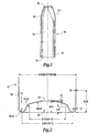
- FIG. 1 is a view of one example of an aluminum can formed by the method of the present invention, partially in cross-section;
- FIG. 2 is a cross-sectional view of the bottom portion of'the aluminum can of FIG. 1 ;
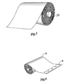
- FIG. 3 is one example of a coil of aluminum alloy feedstock used for this invention.
- FIG. 4 is one example of the coil of aluminum alloy feedstock of FIG. 3 showing metal disks punched from it;
- FIG. 5 is a single metal disk of FIG. 4 made of' a series 3000 aluminum alloy
- FIG. 6 illustrates the disk of FIG. 5 drawn into a cup
- FIG s 7A - 7C illustrate the progression of the cup of FIG. 6 undergoing a reverse draw process to become a second cup having a narrower diameter after completion of the reverse draw process;
- FIG. 8 illustrates one example of a shaped bottom formed in the second cup of FIG 7C ;
- FIG.s 9A - 9D illustrate the progression of the second cup of FIG. 7C or of FIG. 8 through an ironing and trimming process
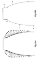
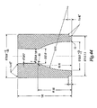
- FIG. 10A shows the resulting shoulder profile of' an aluminum can after the can of FIG. 9D has passed through thirty-four necking dies used according to one embodiment of'the present invention
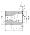
- FIG. 10B illustrates the resulting shoulder of the can of FIG. 10A after it passes through the last necking die used according to one embodiment of the present invention
- FIG.s 11A - 11D are a sequence of views, partially in cross-section, of the aluminum can of FIG. 10B as it undergoes one example of a neck curling process;
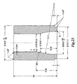
- FIG. 12A is an aluminum can of FIG. 11D having a tapered shoulder
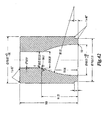
- FIG. 12B is an aluminum can of FIG. 11D having a rounded shoulder
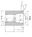
- FIG. 12C is an aluminum can of FIG 11D having a flat shoulder
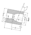
- FIG. 12D is an aluminum can of FIG. 11D having an oval shoulder
- FIG 13 - FIG. 47 are a sequence of cross-sectional views illustrating thirty-five necking dies used according to one embodiment of the present invention.
- FIG. 48 shows a cross-sectional view of the center guides for the first fourteen necking dies used according to one embodiment of the present invention
- FIG. 49 shows a cross-sectional view of the center guides for necking dies number fifteen through thirty-four used for one embodiment of the present invention
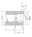
- FIG. 50 illustrates one example of a die holder with a compressed air connection according to the present invention
- FIG. 51 shows an aluminum can of the present invention having a brushed exterior, partially in cross-section
- FIG. 52 shows an aluminum can of the present invention having a threaded aluminum neck, partially in cross-section
- FIG. 53 shows an aluminum can of the present invention having a threaded plastic outsert over the can neck, partially in cross-section.
- the invention will be described with respect to making and necking a drawn and ironed aluminum aerosol can, but it is understood that its application is not limited to such a can.
- the present invention may also be applied to a method of necking other types of aluminum, aluminum bottles, metal containers and shapes.
- the phrase "aerosol can” is used throughout for convenience to mean not only cans, but also aerosol bottles, aerosol containers, non-aerosol bottles, and non-aerosol containers.
- the present invention is an aerosol can and a method for making aluminum alloy cans that perform as well or better than traditional aluminum cans, that allow for high quality printing and design on the cans, that have customized shapes, and that are cost competitive with production of traditional aluminum beverage cans and other steel aerosol cans.
- the target markets for these cans are, among others, the personal care, energy drinks, and pharmaceutical markets.
- a one piece, aluminum aerosol can 10, as seen in FIG. 1 has a generally vertical wall portion 12.
- the generally vertical wall portion 12 is comprised of an upper end 14 and a lower end 16.
- the upper end 14 has a predetermined profile 18, and a neck 19 that has been curled. Alternatively, the neck can be threaded (see FIG.s 52 and 53 ).
- the aluminum can 10 also has a bottom portion 20 extending from the lower end 16. As shown in FIG. 2 , the bottom portion 20 has a U-shaped profile 22 around the periphery of the bottom portion 20 and a wrinkle-free, dome-shaped profile 24 along the remainder of the bottom portion 20.
- the U-shaped profile 22 is preferably 0.51 mm thick.
- the aluminum can 10 of the present invention is made from aluminum alloy coil feedstock 26 as shown in FIG. 3 .
- aluminum alloy coil feedstock 26 is available in a variety of widths. It is desirable to design the production line of the present invention to use one of the commercially available widths to eliminate the need for costly slitting processes.
- the first step in a preferred embodiment of'the present invention is to layout and punch disks 28 from the coil feedstock 26 as is shown in FIG. 4 . It is desirable to layout the disks 28 so as to minimize the amount of unused feedstock 26.
- FIG. 5 shows one of the metal disk 28 punched from a series 3000 aluminum coil feedstock 26. The disk 28 is drawn into a cup 30, as shown in FIG. 6 , using any of the commonly understood methods of making an aluminum cup, but preferably using a method similar to the method of U.S. Patents 5,394,727 and 5,487,295 , which are hereby incorporated by reference.
- the cup 30 is then punched from the bottom to begin to draw the bottom of the can through the sidewalls (a reverse draw).
- FIG. 7B as the stroke continues, the bottom of the cup 30 is drawn deeper so that the walls of the cup develop a lip.
- FIG. 7C the completion of the stroke eliminates the lip altogether resulting in a second cup 34 that is typically narrower in diameter than the original cup 30.
- the second cup 34 may be drawn one or more additional times, resulting in an even narrower diameter.
- the resulting cup 34 has the vertical wall portion 12 and the lower end 16 with the bottom portion 20
- the bottom portion 20 maybe shaped as shown in FIG.s 8 and 2 .
- the domed configuration illustrated herein is particularly useful for containers that are pressurized.
- the vertical wall portion 12 is ironed multiple times until it is of a desired height and thickness, preferably 0.21 mm thick.
- the vertical wall portion 12 should be of sufficient thickness to withstand the internal pressure for the intended use. For example, some aerosol products require a can that withstands an internal pressure of 270 psi or DOT 2Q.
- the ironing process also compacts the wall making it stronger
- the upper end 14 of the vertical wall portion 12 is trimmed to produce an aluminum can 10, as shown in FIG. 9D .
- the can 10 is attached to a first mandrel and passed through a first series of necking dies. Subsequently, the can 10 is attached to a second mandrel and passed through a second series of necking dies. In the embodiment illustrated, the can 10 will pass through up to more than thirty necking dies. These necking dies shape the can 10 as shown in FIG.s 10A and 10B . Each die is designed to impart a desired shape to the upper end 14 of'the generally vertical wall portion 12 of the can 10, so that by the end of the necking process ( FIG. 10B ), the upper end 14 has the desired profile 18 and the neck 19.
- the can 10, partially shown in FIG. 10B is shown in full in FIG. 11A .
- the neck 19 of'the can 10 is curled through a series of curling steps.
- the resulting aerosol can 10 of the present invention (as shown in both FIG. 11D and FIG 1 ) has the predetermined shoulder profile 18, the curled neck 19, and is adapted to receive an aerosol-dispensing device.
- the predetermined shoulder profile 18 can be a variety of shapes including, that of a tapered shoulder, a rounded shoulder, a flat shoulder, and an oval shoulder, respectfully.
- the resulting aluminum may be between 100 and 200 mm in height and 45 and 66 mm in diameter.
- the aluminum can may be customized in a variety of ways. One way would be to add texture the surface of the can, for example, by brushing the surface of the can as shown in FIG. 51 .
- the predetermined shoulder profile can be adapted to receive an aerosol-dispensing device.
- the predetermined shoulder profile can also extend into or carry a neck, threaded or not (see FIG.s 52 and 53 ). An aluminum neck without threading can carry a threaded plastic outsert, as shown in FIG. 53 .
- the present invention also encompasses a method of forming a shoulder profile in an aluminum can made of a series 3000, e.g. 3004, aluminum alloy.
- the first step of this method entails attaching the aluminum can to a first mandrel.
- the can is then passed sequentially through a first series of up to and including twenty-eight necking dies that are arranged on a necking table in a circular pattern
- the can is then transferred to a second mandrel. While on the second mandrel, the can is sequentially passed through a second series of up to and including twenty-eight necking dies which are arranged in a circular pattern on a second necking table.
- This method includes trimming the neck after the can passes through a certain predetermined number of necking dies.
- one of' the necking dies is replaced with a trimming station. Trimming eliminates excess material and irregular edges at the neck of the can and helps to prevent the can from sticking in the remaining necking dies.
- a sufficient number of necking dies will be used so as to effect the maximum incremental radial deformation of the can in each necking die that is possible while ensuring that the can remains easily removable from each necking die. Effecting the maximum incremental radial deformation is desirable for efficient can production.
- at least 2° of radial deformation can be achieved with each die after the first die, which may impart less than 2° of the deformation.
- FIG.s 13 through 47 The shape and degree of taper imposed by each die onto the can is shown in FIG.s 13 through 47 .
- the method of the present invention may use a stationary center guide as shown in FIG. 48 for each of the first fourteen necking dies.
- FIG. 49 shows the center guides for the necking dies 15 through 34. Compressed air can also be used to aid the removal of'the can from the first several necking dies. For other shoulder profiles, movable guides and compressed air can be used on all necking positions
- FIG. 50 shows a general die holder with a compressed air connection.
- the necking dies used in the method and apparatus of the present invention differ from traditional necking dies in several ways. Each die imparts a smaller degree of deformation than the necking dies of the prior art.
- the angle at the back of the first necking die is 0°30'0" (zero degrees, thirty minutes, zero seconds).
- the angle at the backs of'dies two through six is 3° instead of the traditional 30°.
- the necking dies of the present invention are also longer than those traditionally used, preferably they are 100 mm in length.
Abstract
Description
- The present invention is directed to aerosol cans and, more particularly, to aerosol cans constructed of aluminum.
- Traditionally, beverage cans begin as disks of aluminum coil feedstock that are processed into the shape of a beverage can The sides of these cans are approximately 0.13 mm thick. Generally, the body of a beverage can, excluding the top, is one piece.
- In contrast, aerosol cans are traditionally made one of two ways. First, they can be made from three pieces of steel, a top piece, a bottom piece, and a cylindrical sidewall having a weld seem running the length of the sidewall. These three pieces are assembled to form the can. Aerosol cans may also be made from a process known as impact extrusion. In an impact extrusion process, a hydraulic ram punches an aluminum slug to begin forming the can. The sides of the can are thinned to approximately 0.40 mm through an ironing process that lengthens the walls of the can. The rough edges of the wall are trimmed and the can is passed through a serves of necking dies to form the top of'the can Although aerosol cans made of steel are less expensive than aerosol cans made by an impact extrusion process, steel cans are aesthetically much less desirable than aerosol cans made with an impact extrusion process.
- For a variety of reasons, aluminum aerosol cans are significantly more expensive to produce than aluminum beverage cans. First, more aluminum is used in an aerosol can than in a beverage can. Second, the production of aluminum cans by impact extrusion is limited by the maximum speed of the hydraulic ram of the press. Theoretically, the maximum speed of the ram is 200 strokes/minute Practically, the speed is 180 slugs/minute. Beverage cans are made at a rate of 2,400 cans/minute.
- One problem facing the aerosol can industry is producing an aluminum aerosol can that performs as well or better than traditional aerosol cans but is economically competitive with the cost of producing steel aerosol cans and aluminum beverage cans.. Another problem is producing an aerosol can that has the printing and design quality demanded by designers of high-end products Traditional beverage cans are limited in the clarity of printing and design that can be imprinted on the cans. Beverage cans are also limited in the number of colors that can be used in can designs. Thus, a need exits for an aluminum aerosol can that has the attributes of strength and quality, while being produced at a cost that is competitive with steel aerosol cans.
- Producing aluminum cans of a series 3000 aluminum alloy coil feedstock solves some of these problems. Series 3000 aluminum alloy coil feedstock can be shaped into a can using a reverse draw and ironing process, which is significantly faster and more cost effective than impact extrusion, aluminum can production. Additionally, series 3000 aluminum alloy is less expensive, more cost effective, and allows for better quality printing and graphics than the use of pure aluminum.
- Unfortunately, certain obstacles arise in necking a series 3000 aluminum alloy can. Series 3000 aluminum alloy is a harder material than pure aluminum. Therefore, cans made from series 3000 aluminum alloy are stiffer and have more memory. This is advantageous because the cans are more dent resistant, but it poses problems in necking the cans by traditional means because the cans stick in traditional necking dies and jam traditional necking machines. The solution to these obstacles is embodied in the method of the present invention.
- This invention relates to a method for making and necking an aluminum aerosol can from a disk of aluminum alloy coil feedstock where the method is designed to, among other things, present the can from sticking in the necking dies. Additionally, this invention relates to the aluminum aerosol can itself, which has a uniquely shaped profile and is made from aluminum alloy of' the 3000 series.
- The aluminum can of the present invention is comprised of a generally vertical wall portion having an upper end and a lower end, where the upper end has a predetermined profile. A bottom portion, extending from the lower end of the can, has a U-shaped profile around its periphery and a dome-shaped profile along the remainder of the bottom portion. Preferably, the generally vertical wall portion is approximately 0.20 mm thick, and the bottom portion is approximately 0.51 mm thick in the area of the U-shaped profile.
- The present invention is also directed to a method of forming a neck profile in an aluminum can made of a series 3000 aluminum alloy, where the can is processed with at least 30 different necking dies. This invention solves the problems of necking a series 3000 aluminum alloy can by increasing the number of necking dies used and decreasing the degree of deformation that is imparted with each die. A traditional aerosol can, made from pure aluminum, which is 45 mm to 66 mm in diameter, requires the use of 17 or less necking dies. A can made by the present invention, of similar diameters, made from a series 3000 aluminum alloy requires the use of, for example, thirty or more necking dies. Generally, the number of dies that are needed to neck a can of the present invention depends on the profile of the can The present invention processes the aluminum can sequentially through a sufficient number of necking dies so as to effect the maximum incremental radial deformation of the can in each necking die while ensuring that the can remains easily removable from each necking die.
- There are several advantages of'the can and method of the present invention. Overall, the process is faster, less expensive, and more efficient than the traditional method of impact extrusion, aerosol can production. The disclosed method of production uses a less expensive, recyclable aluminum alloy instead of pure aluminum. The disclosed can is more desirable than a steel can for a variety of reasons. Aluminum is resistant to moisture and does not corrode or rust. Furthermore, because of the shoulder configuration of a steel can, the cap configuration is always the same and cannot be varied to give customers an individualized look This is not so with the present invention in which the can shoulder may be customized. Finally, aluminum cans are aesthetically more desirable. For example, the cans may be brushed and/or a threaded neck may be formed in the top of the can. Those advantages and benefits and others, will be apparent from the Description of the Preferred Embodiments within.
- For the present invention to be easily understood and readily practiced, the present invention will now be described, for purposes of illustration and not limitation, in conjunction with the following figures, wherein:
-
FIG. 1 is a view of one example of an aluminum can formed by the method of the present invention, partially in cross-section; -
FIG. 2 is a cross-sectional view of the bottom portion of'the aluminum can ofFIG. 1 ; -
FIG. 3 is one example of a coil of aluminum alloy feedstock used for this invention; -
FIG. 4 is one example of the coil of aluminum alloy feedstock ofFIG. 3 showing metal disks punched from it; -
FIG. 5 is a single metal disk ofFIG. 4 made of' a series 3000 aluminum alloy; -
FIG. 6 illustrates the disk ofFIG. 5 drawn into a cup; - FIG s 7A - 7C illustrate the progression of the cup of
FIG. 6 undergoing a reverse draw process to become a second cup having a narrower diameter after completion of the reverse draw process; -
FIG. 8 illustrates one example of a shaped bottom formed in the second cup ofFIG 7C ; -
FIG.s 9A - 9D illustrate the progression of the second cup ofFIG. 7C or ofFIG. 8 through an ironing and trimming process; -
FIG. 10A shows the resulting shoulder profile of' an aluminum can after the can ofFIG. 9D has passed through thirty-four necking dies used according to one embodiment of'the present invention; -
FIG. 10B illustrates the resulting shoulder of the can ofFIG. 10A after it passes through the last necking die used according to one embodiment of the present invention; -
FIG.s 11A - 11D are a sequence of views, partially in cross-section, of the aluminum can ofFIG. 10B as it undergoes one example of a neck curling process; -
FIG. 12A is an aluminum can ofFIG. 11D having a tapered shoulder; -
FIG. 12B is an aluminum can ofFIG. 11D having a rounded shoulder; -
FIG. 12C is an aluminum can ofFIG 11D having a flat shoulder; -
FIG. 12D is an aluminum can ofFIG. 11D having an oval shoulder; -
FIG 13 - FIG. 47 are a sequence of cross-sectional views illustrating thirty-five necking dies used according to one embodiment of the present invention; -
FIG. 48 shows a cross-sectional view of the center guides for the first fourteen necking dies used according to one embodiment of the present invention; -
FIG. 49 shows a cross-sectional view of the center guides for necking dies number fifteen through thirty-four used for one embodiment of the present invention; -
FIG. 50 illustrates one example of a die holder with a compressed air connection according to the present invention; -
FIG. 51 shows an aluminum can of the present invention having a brushed exterior, partially in cross-section; -
FIG. 52 shows an aluminum can of the present invention having a threaded aluminum neck, partially in cross-section; and -
FIG. 53 shows an aluminum can of the present invention having a threaded plastic outsert over the can neck, partially in cross-section. - For ease of description and illustration, the invention will be described with respect to making and necking a drawn and ironed aluminum aerosol can, but it is understood that its application is not limited to such a can. The present invention may also be applied to a method of necking other types of aluminum, aluminum bottles, metal containers and shapes. It will also be appreciated that the phrase "aerosol can" is used throughout for convenience to mean not only cans, but also aerosol bottles, aerosol containers, non-aerosol bottles, and non-aerosol containers.
- The present invention is an aerosol can and a method for making aluminum alloy cans that perform as well or better than traditional aluminum cans, that allow for high quality printing and design on the cans, that have customized shapes, and that are cost competitive with production of traditional aluminum beverage cans and other steel aerosol cans. The target markets for these cans are, among others, the personal care, energy drinks, and pharmaceutical markets.
- A one piece, aluminum aerosol can 10, as seen in
FIG. 1 , has a generallyvertical wall portion 12. The generallyvertical wall portion 12 is comprised of anupper end 14 and alower end 16. Theupper end 14 has a predeterminedprofile 18, and aneck 19 that has been curled. Alternatively, the neck can be threaded (seeFIG.s 52 and 53 ). The aluminum can 10 also has abottom portion 20 extending from thelower end 16. As shown inFIG. 2 , thebottom portion 20 has aU-shaped profile 22 around the periphery of thebottom portion 20 and a wrinkle-free, dome-shapedprofile 24 along the remainder of thebottom portion 20. TheU-shaped profile 22 is preferably 0.51 mm thick. - The aluminum can 10 of the present invention is made from aluminum
alloy coil feedstock 26 as shown inFIG. 3 . As is known, aluminumalloy coil feedstock 26 is available in a variety of widths. It is desirable to design the production line of the present invention to use one of the commercially available widths to eliminate the need for costly slitting processes. - The first step in a preferred embodiment of'the present invention is to layout and punch
disks 28 from thecoil feedstock 26 as is shown inFIG. 4 . It is desirable to layout thedisks 28 so as to minimize the amount ofunused feedstock 26.FIG. 5 shows one of themetal disk 28 punched from a series 3000aluminum coil feedstock 26. Thedisk 28 is drawn into acup 30, as shown inFIG. 6 , using any of the commonly understood methods of making an aluminum cup, but preferably using a method similar to the method ofU.S. Patents 5,394,727 and5,487,295 , which are hereby incorporated by reference. - As shown in
FIG. 7A , thecup 30 is then punched from the bottom to begin to draw the bottom of the can through the sidewalls (a reverse draw). As shown inFIG. 7B , as the stroke continues, the bottom of thecup 30 is drawn deeper so that the walls of the cup develop a lip. As shown inFIG. 7C , the completion of the stroke eliminates the lip altogether resulting in asecond cup 34 that is typically narrower in diameter than theoriginal cup 30. Thesecond cup 34 may be drawn one or more additional times, resulting in an even narrower diameter. The resultingcup 34 has thevertical wall portion 12 and thelower end 16 with thebottom portion 20 Thebottom portion 20 maybe shaped as shown inFIG.s 8 and2 . Although other configurations may be used, the domed configuration illustrated herein is particularly useful for containers that are pressurized. - As shown in
FIG.s 9A through 9D , thevertical wall portion 12 is ironed multiple times until it is of a desired height and thickness, preferably 0.21 mm thick. Thevertical wall portion 12 should be of sufficient thickness to withstand the internal pressure for the intended use. For example, some aerosol products require a can that withstands an internal pressure of 270 psi or DOT 2Q. The ironing process also compacts the wall making it stronger Theupper end 14 of thevertical wall portion 12 is trimmed to produce analuminum can 10, as shown inFIG. 9D . - According to one embodiment of the present invention, the
can 10 is attached to a first mandrel and passed through a first series of necking dies. Subsequently, thecan 10 is attached to a second mandrel and passed through a second series of necking dies. In the embodiment illustrated, thecan 10 will pass through up to more than thirty necking dies. These necking dies shape thecan 10 as shown inFIG.s 10A and 10B . Each die is designed to impart a desired shape to theupper end 14 of'the generallyvertical wall portion 12 of thecan 10, so that by the end of the necking process (FIG. 10B ), theupper end 14 has the desiredprofile 18 and theneck 19. - The
can 10, partially shown inFIG. 10B , is shown in full inFIG. 11A . As shown inFIG.s 11A through 11D , theneck 19 of'the can 10 is curled through a series of curling steps. The resulting aerosol can 10 of the present invention (as shown in bothFIG. 11D andFIG 1 ) has the predeterminedshoulder profile 18, the curledneck 19, and is adapted to receive an aerosol-dispensing device. As shown inFIG.s 12A through 12D , thepredetermined shoulder profile 18 can be a variety of shapes including, that of a tapered shoulder, a rounded shoulder, a flat shoulder, and an oval shoulder, respectfully. The resulting aluminum can may be between 100 and 200 mm in height and 45 and 66 mm in diameter. The aluminum can may be customized in a variety of ways. One way would be to add texture the surface of the can, for example, by brushing the surface of the can as shown inFIG. 51 . Additionally, the predetermined shoulder profile can be adapted to receive an aerosol-dispensing device. The predetermined shoulder profile can also extend into or carry a neck, threaded or not (seeFIG.s 52 and 53 ). An aluminum neck without threading can carry a threaded plastic outsert, as shown inFIG. 53 . - The present invention also encompasses a method of forming a shoulder profile in an aluminum can made of a series 3000, e.g. 3004, aluminum alloy. The first step of this method entails attaching the aluminum can to a first mandrel. The can is then passed sequentially through a first series of up to and including twenty-eight necking dies that are arranged on a necking table in a circular pattern The can is then transferred to a second mandrel. While on the second mandrel, the can is sequentially passed through a second series of up to and including twenty-eight necking dies which are arranged in a circular pattern on a second necking table. This method includes trimming the neck after the can passes through a certain predetermined number of necking dies. That is, one of' the necking dies is replaced with a trimming station. Trimming eliminates excess material and irregular edges at the neck of the can and helps to prevent the can from sticking in the remaining necking dies. A sufficient number of necking dies will be used so as to effect the maximum incremental radial deformation of the can in each necking die that is possible while ensuring that the can remains easily removable from each necking die. Effecting the maximum incremental radial deformation is desirable for efficient can production. A problem arises when the deformation is too great, thus causing the can to stick inside the necking die and jam the die necking machine. Generally, at least 2° of radial deformation can be achieved with each die after the first die, which may impart less than 2° of the deformation.
- The shape and degree of taper imposed by each die onto the can is shown in
FIG.s 13 through 47 . The method of the present invention may use a stationary center guide as shown inFIG. 48 for each of the first fourteen necking dies.FIG. 49 shows the center guides for the necking dies 15 through 34. Compressed air can also be used to aid the removal of'the can from the first several necking dies. For other shoulder profiles, movable guides and compressed air can be used on all necking positionsFIG. 50 shows a general die holder with a compressed air connection. - The necking dies used in the method and apparatus of the present invention differ from traditional necking dies in several ways. Each die imparts a smaller degree of deformation than the necking dies of the prior art. The angle at the back of the first necking die is 0°30'0" (zero degrees, thirty minutes, zero seconds). The angle at the backs of'dies two through six is 3° instead of the traditional 30°. The necking dies of the present invention are also longer than those traditionally used, preferably they are 100 mm in length. These changes minimize problems associated with the memory of the can walls, which memory may cause the can to stick in traditional necking dies. Additionally, in the test runs, the top of'the can was pinched and was sticking on the center guide of traditional dies. Therefore, the first fourteen necking dies have non-movable center guides. Finally, the present invention uses compressed air to help force the cans off and out of each necking die. The compressed air also helps to support the can walls.
- While the present invention has been described in connection with preferred embodiments thereof, those of ordinary skill in the art will recognize that many modifications and variations may be made without departing from the spirit and scope of the present invention. The present invention is not to be limited by the foregoing description, but only by the following claims.
Claims (16)
- An aluminum can comprising a wall portion (12) having an upper end (14) and a lower end (16), and a bottom portion (20) extending from said lower end (16) of said wall portion (12), said bottom portion (20) having a predetermined profile, characterized in that said can is formed from a series 3000 aluminum and said upper end (14) defines a predetermined shoulder profile (18) and a neck (19)
- The aluminum can of claim 1 wherein said predetermined shoulder profile includes one of a tapered shoulder, rounded shoulder, flat shoulder, and oval shoulder.
- The aluminum can of claim 1 wherein said can is between 100 and 200 mm in height and 45 and 66 mm in diameter.
- The aluminum can of claim 1 wherein said neck is adapted to receive an aerosol-dispensing device.
- The aluminum can of claim 1 wherein said profile of said bottom portion includes a U-shaped profile around the periphery of said bottom portion and a dome-shaped profile along the remainder of said bottom portion.
- The aluminum can of claim 5 wherein the dome-shaped profile of said bottom portion is free from wrinkles.
- The aluminum can of claim 5 wherein said generally vertical wall portion has a thickness of approximately 0.21 mm and said bottom portion has a thickness of' approximately 0.51 mm in the area of said U-shaped profile.
- A method of forming a shoulder profile in an aluminum can constructed of' a series 3000 aluminum alloy, comprising processing said can with at least thirty different necking dies.
- The method of claim 8 wherein said processing comprises die necking the can with a first necking die having an angle of 0°30'0" at the back of said first die.
- The method of claim 9 wherein said processing comprises die necking the can with a second necking die having an angle of 3° at the back of said second die.
- The method of claim 10 wherein said processing comprises die necking the can with a third necking die having an angle of 3° at the back of said third die.
- The method of claim 11 wherein said processing comprises die necking the can with a fourth necking die having an angle of 3° at the back of said fourth die.
- The method of claim 8 wherein said processing comprises die necking the can with a series of fourteen necking dies have non-movable center guides.
- The method of claim 8 additionally comprising using compressed air with the first fourteen dies to aid in the removal of said can from each of said dies.
- The method of claim 8 wherein each of said necking dies achieves a degree of' taper that is between about 0°30'0" to 3" from the original vertical sidewall of said can,
- The method of claim 8 wherein said necking dies are arranged in two circular paths.
Priority Applications (1)
| Application Number | Priority Date | Filing Date | Title |
|---|---|---|---|
| SI200332459T SI2119515T1 (en) | 2002-08-20 | 2003-06-27 | Method for manufacturing an aluminium aerosol can from coil feedstock |
Applications Claiming Priority (3)
| Application Number | Priority Date | Filing Date | Title |
|---|---|---|---|
| US10/224,256 US20040035871A1 (en) | 2002-08-20 | 2002-08-20 | Aluminum aerosol can and aluminum bottle and method of manufacture |
| EP06016571.9A EP1731239B8 (en) | 2002-08-20 | 2003-06-27 | Aluminium areosol can manufactured from coil feedstock |
| EP03742275A EP1531952B1 (en) | 2002-08-20 | 2003-06-27 | Aluminum aerosol can and aluminum bottle and method of manufacture from coil feedstock |
Related Parent Applications (5)
| Application Number | Title | Priority Date | Filing Date |
|---|---|---|---|
| EP03742275.5 Division | 2003-06-27 | ||
| EP06016571.9A Division EP1731239B8 (en) | 2002-08-20 | 2003-06-27 | Aluminium areosol can manufactured from coil feedstock |
| EP06016571.9A Division-Into EP1731239B8 (en) | 2002-08-20 | 2003-06-27 | Aluminium areosol can manufactured from coil feedstock |
| EP03742275A Division EP1531952B1 (en) | 2002-08-20 | 2003-06-27 | Aluminum aerosol can and aluminum bottle and method of manufacture from coil feedstock |
| EP06016571.9 Division | 2006-08-08 |
Publications (3)
| Publication Number | Publication Date |
|---|---|
| EP2119515A2 true EP2119515A2 (en) | 2009-11-18 |
| EP2119515A3 EP2119515A3 (en) | 2011-11-30 |
| EP2119515B1 EP2119515B1 (en) | 2015-10-14 |
Family
ID=31886779
Family Applications (3)
| Application Number | Title | Priority Date | Filing Date |
|---|---|---|---|
| EP09168593.3A Expired - Lifetime EP2119515B1 (en) | 2002-08-20 | 2003-06-27 | Method for manufacturing an aluminium aerosol can from coil feedstock |
| EP06016571.9A Expired - Lifetime EP1731239B8 (en) | 2002-08-20 | 2003-06-27 | Aluminium areosol can manufactured from coil feedstock |
| EP03742275A Revoked EP1531952B1 (en) | 2002-08-20 | 2003-06-27 | Aluminum aerosol can and aluminum bottle and method of manufacture from coil feedstock |
Family Applications After (2)
| Application Number | Title | Priority Date | Filing Date |
|---|---|---|---|
| EP06016571.9A Expired - Lifetime EP1731239B8 (en) | 2002-08-20 | 2003-06-27 | Aluminium areosol can manufactured from coil feedstock |
| EP03742275A Revoked EP1531952B1 (en) | 2002-08-20 | 2003-06-27 | Aluminum aerosol can and aluminum bottle and method of manufacture from coil feedstock |
Country Status (20)
| Country | Link |
|---|---|
| US (3) | US20040035871A1 (en) |
| EP (3) | EP2119515B1 (en) |
| JP (1) | JP4496077B2 (en) |
| CN (1) | CN100488660C (en) |
| AR (1) | AR040952A1 (en) |
| AT (2) | ATE441492T1 (en) |
| AU (1) | AU2003290205A1 (en) |
| BR (1) | BR0313014B1 (en) |
| CA (1) | CA2495205C (en) |
| DE (2) | DE60307478T2 (en) |
| ES (3) | ES2332323T5 (en) |
| HK (1) | HK1083790A1 (en) |
| HU (1) | HUE025841T2 (en) |
| MX (1) | MXPA05001974A (en) |
| NO (1) | NO20051338L (en) |
| RU (1) | RU2323797C2 (en) |
| SI (3) | SI1731239T2 (en) |
| UA (1) | UA85045C2 (en) |
| WO (1) | WO2004018121A1 (en) |
| ZA (1) | ZA200500493B (en) |
Cited By (17)
| Publication number | Priority date | Publication date | Assignee | Title |
|---|---|---|---|---|
| USD686078S1 (en) | 2010-10-29 | 2013-07-16 | Ball Corporation | Beverage container with cap |
| USD686079S1 (en) | 2010-10-29 | 2013-07-16 | Ball Corporation | Beverage container with cap |
| USD688949S1 (en) | 2010-10-29 | 2013-09-03 | Ball Corporation | Beverage container with cap |
| USD696116S1 (en) | 2011-03-02 | 2013-12-24 | Ball Corporation | Beverage container |
| USD696946S1 (en) | 2013-04-25 | 2014-01-07 | Ball Corporation | Metal bottle |
| USD697407S1 (en) | 2012-11-13 | 2014-01-14 | Ball Corporation | Metal beverage container |
| USD702553S1 (en) | 2013-03-07 | 2014-04-15 | Ball Corporation | Metallic beverage container |
| USD725472S1 (en) | 2012-01-25 | 2015-03-31 | Ball Corporation | Beverage container |
| USD734154S1 (en) | 2011-03-02 | 2015-07-14 | Ball Corporation | Beverage container |
| US9663846B2 (en) | 2011-09-16 | 2017-05-30 | Ball Corporation | Impact extruded containers from recycled aluminum scrap |
| US9844805B2 (en) | 2013-04-09 | 2017-12-19 | Ball Corporation | Aluminum impact extruded bottle with threaded neck made from recycled aluminum and enhanced alloys |
| USD857505S1 (en) | 2015-01-05 | 2019-08-27 | Ball Corporation | Metal bottle |
| USD858287S1 (en) | 2014-09-15 | 2019-09-03 | Ball Corporation | Metal bottle |
| US10875684B2 (en) | 2017-02-16 | 2020-12-29 | Ball Corporation | Apparatus and methods of forming and applying roll-on pilfer proof closures on the threaded neck of metal containers |
| US11185909B2 (en) | 2017-09-15 | 2021-11-30 | Ball Corporation | System and method of forming a metallic closure for a threaded container |
| US11459223B2 (en) | 2016-08-12 | 2022-10-04 | Ball Corporation | Methods of capping metallic bottles |
| US11519057B2 (en) | 2016-12-30 | 2022-12-06 | Ball Corporation | Aluminum alloy for impact extruded containers and method of making the same |
Families Citing this family (65)
| Publication number | Priority date | Publication date | Assignee | Title |
|---|---|---|---|---|
| RS51668B (en) | 2005-05-25 | 2011-10-31 | Ball Packaging Europe Gmbh. | Closure with guide columns for a container |
| WO2006125772A2 (en) * | 2005-05-25 | 2006-11-30 | Ball Packaging Europe Gmbh | Tin lid with guide posts for a container |
| US20070080128A1 (en) * | 2005-10-10 | 2007-04-12 | Laveault Richard A | Beverage container with threaded plastic drinking sleeve |
| US7946436B2 (en) * | 2005-10-10 | 2011-05-24 | Rieke Corporation | Beverage container with threaded plastic drinking sleeve |
| US7726165B2 (en) * | 2006-05-16 | 2010-06-01 | Alcoa Inc. | Manufacturing process to produce a necked container |
| US7934410B2 (en) * | 2006-06-26 | 2011-05-03 | Alcoa Inc. | Expanding die and method of shaping containers |
| EP1889673A1 (en) * | 2006-08-17 | 2008-02-20 | Corus Staal BV | Method for manufacturing a metal container |
| EP1927554A1 (en) * | 2006-11-29 | 2008-06-04 | Impress Group B.V. | Pressurized can, such as an aerosol can |
| BRPI0702306A2 (en) * | 2007-05-21 | 2009-01-13 | Vlademir Moreno | tugging process for forming pre-lash-shaped metal packaging, and tugging equipment for pre-lash-forming metal packaging |
| US8601843B2 (en) | 2008-04-24 | 2013-12-10 | Crown Packaging Technology, Inc. | High speed necking configuration |
| WO2010010128A2 (en) * | 2008-07-22 | 2010-01-28 | Henkel Ag & Co. Kgaa | Foamable low-viscosity mixtures |
| US8903528B2 (en) * | 2008-10-16 | 2014-12-02 | The Coca-Cola Company | Remote control and management of a vessel forming production line |
| US8381561B2 (en) * | 2008-10-16 | 2013-02-26 | The Coca-Cola Company | Vessel forming production line |
| US8726709B2 (en) * | 2008-10-16 | 2014-05-20 | The Coca-Cola Company | Method of shape forming vessels controlling rotational indexing |
| US8448487B2 (en) * | 2008-10-16 | 2013-05-28 | The Coca-Cola Company | Vessel forming station |
| US8627697B2 (en) * | 2008-10-16 | 2014-01-14 | The Coca-Cola Company | Method of performing non vessel shaping operations during vessel shaping |
| US8726710B2 (en) * | 2008-10-16 | 2014-05-20 | The Coca-Cola Company | Method of coordinating vessel shape style and decoration style |
| US9067254B2 (en) * | 2008-10-16 | 2015-06-30 | The Coca-Cola Company | Method of configuring a production line to mass customize shaped vessels |
| US20100107719A1 (en) * | 2008-10-31 | 2010-05-06 | Jeffrey Edward Geho | Necking die with shortened land and method of die necking |
| WO2010053146A1 (en) * | 2008-11-07 | 2010-05-14 | 株式会社Jetovo | Method for producing cylinder, cylinder and ejection device using cylinder |
| JP2011092977A (en) * | 2009-10-29 | 2011-05-12 | Jetovo Corp | Method for producing cylinder, cylinder and ejection device using the cylinder |
| JP2010112497A (en) * | 2008-11-07 | 2010-05-20 | Jetovo Corp | Method for manufacturing cylinder and the cylinder |
| JP5323757B2 (en) * | 2009-04-06 | 2013-10-23 | 武内プレス工業株式会社 | Metal bottle cans |
| US20110113732A1 (en) * | 2009-11-13 | 2011-05-19 | The Coca-Cola Company | Method of isolating column loading and mitigating deformation of shaped metal vessels |
| US8360266B2 (en) * | 2009-11-13 | 2013-01-29 | The Coca-Cola Corporation | Shaped metal vessel |
| MX2012011886A (en) * | 2010-04-13 | 2012-11-30 | Crown Packaging Technology Inc | Can manufacture. |
| KR102101137B1 (en) * | 2010-08-20 | 2020-04-14 | 알코아 유에스에이 코포레이션 | Shaped metal container and method for making same |
| ES2426147T3 (en) * | 2011-01-12 | 2013-10-21 | Ardagh Mp Group Netherlands B.V. | Pressurized metal container and pressurized metal container preform and a method to do so |
| USD656822S1 (en) | 2011-03-02 | 2012-04-03 | Ball Corporation | Beverage container |
| US9327372B2 (en) | 2011-08-10 | 2016-05-03 | Timothy J. Farnham | Clamp rod assembly |
| DE102011056462B4 (en) * | 2011-12-15 | 2014-08-28 | Schuler Pressen Gmbh | Method for producing a container body |
| JP6099319B2 (en) * | 2012-04-27 | 2017-03-22 | 北海製罐株式会社 | Mixed aerosol container |
| US9254514B2 (en) * | 2012-05-02 | 2016-02-09 | Farnham Enterprises, Llc | Methods and processes of manufacturing two piece cans |
| USD787952S1 (en) | 2012-08-29 | 2017-05-30 | Ball Corporation | Contoured neck for a beverage container |
| US8678211B1 (en) * | 2012-10-24 | 2014-03-25 | Shin-Shuoh Lin | Pressed double layer lip hydration bottle |
| US9327338B2 (en) | 2012-12-20 | 2016-05-03 | Alcoa Inc. | Knockout for use while necking a metal container, die system for necking a metal container and method of necking a metal container |
| USD744861S1 (en) | 2013-03-14 | 2015-12-08 | Crown Packaging Technology, Inc. | Aerosol can |
| HUE038889T2 (en) | 2013-03-14 | 2018-12-28 | Crown Packaging Technology Inc | Drawn and ironed aerosol can |
| US9821926B2 (en) | 2013-03-15 | 2017-11-21 | Ball Corporation | Method and apparatus for forming a threaded neck on a metallic bottle |
| FR3005664B1 (en) * | 2013-05-17 | 2016-05-27 | Constellium France | ALLOY ALLOY SHEET FOR METAL BOTTLE OR AEROSOL HOUSING |
| JP5745583B2 (en) * | 2013-09-04 | 2015-07-08 | 株式会社Jetovo | Cylinder manufacturing method and cylinder |
| EP2851141A1 (en) | 2013-09-20 | 2015-03-25 | Moravia Cans a.s. | Method for shaping containers and a device for production thereof |
| EP3633053A1 (en) | 2014-04-30 | 2020-04-08 | Alcoa USA Corp. | Method of manufacturing an aluminum container made from aluminum sheet |
| US9358604B2 (en) | 2014-06-12 | 2016-06-07 | Ball Corporation | System for compression relief shaping |
| USD742251S1 (en) | 2014-07-16 | 2015-11-03 | Ball Corporation | Two-piece contoured metallic container |
| USD758207S1 (en) | 2014-08-08 | 2016-06-07 | Ball Corporation | Two-piece contoured metallic container |
| US20160122068A1 (en) * | 2014-10-12 | 2016-05-05 | Michael Butter | Beverage container |
| BR112017007384A2 (en) * | 2014-10-15 | 2017-12-19 | Ball Corp | metal container shoulder and neck forming apparatus and process |
| AU2015339316A1 (en) | 2014-10-28 | 2017-04-27 | Ball Corporation | Apparatus and method for forming a cup with a reformed bottom |
| USD813673S1 (en) * | 2015-06-30 | 2018-03-27 | Kronebusch Industries, Llc | Spray container |
| US10159862B2 (en) | 2015-06-30 | 2018-12-25 | Kronebusch Industries, Llc | Fire extinguisher with recessed gauge |
| USD804309S1 (en) | 2016-02-17 | 2017-12-05 | Ball Corporation | Metal bottle |
| USD827685S1 (en) * | 2016-12-19 | 2018-09-04 | Stolle Machinery Company, Llc | Truncated dome cup |
| USD839935S1 (en) * | 2016-12-19 | 2019-02-05 | Stolle Machinery Company, Llc | Truncated dome cup |
| US10843864B2 (en) * | 2017-05-17 | 2020-11-24 | Ball Metalpack, Llc | Metallic container dome configured to deform at a predetermined pressure |
| JP7039943B2 (en) * | 2017-11-14 | 2022-03-23 | 東洋製罐株式会社 | Bottle can manufacturing equipment and bottle can manufacturing method |
| SI3498393T1 (en) | 2017-12-18 | 2022-01-31 | Moravia Cans A.S. | Tool for curling of can s neck |
| US10807144B2 (en) | 2017-12-20 | 2020-10-20 | Moravia Cans A.S. | Tool for curling of can necks |
| USD932924S1 (en) * | 2019-03-15 | 2021-10-12 | Exal Corporation | Aerosol can |
| USD946405S1 (en) * | 2019-03-20 | 2022-03-22 | Ball Corporation | Metal food container |
| CN110217464B (en) * | 2019-06-29 | 2024-01-23 | 广州荣鑫容器有限公司 | Manufacturing method of 568-580ml metal can |
| CA3148034A1 (en) * | 2019-07-29 | 2021-02-04 | Ball Corporation | Domed container with nitrogen well and closure mechanism |
| USD982458S1 (en) | 2019-10-24 | 2023-04-04 | Ball Corporation | Metal food container |
| CN114502298A (en) * | 2019-11-11 | 2022-05-13 | 东洋制罐株式会社 | Can body forming device |
| RU2744804C1 (en) * | 2020-09-04 | 2021-03-15 | Акционерное общество "Конструкторское бюро химавтоматики" (АО КБХА) | Method for manufacturing hollow bottle-shaped part |
Citations (2)
| Publication number | Priority date | Publication date | Assignee | Title |
|---|---|---|---|---|
| US5718352A (en) | 1994-11-22 | 1998-02-17 | Aluminum Company Of America | Threaded aluminum cans and methods of manufacture |
| US5778723A (en) | 1992-07-31 | 1998-07-14 | Aluminum Company Of America | Method and apparatus for necking a metal container and resultant container |
Family Cites Families (33)
| Publication number | Priority date | Publication date | Assignee | Title |
|---|---|---|---|---|
| US3733881A (en) † | 1970-09-28 | 1973-05-22 | Shape Farm Inc | Method and apparatus for making deep drawn metal shells |
| US4414836A (en) * | 1982-09-30 | 1983-11-15 | National Steel Corporation | Method of and apparatus for deep drawing metal containers |
| US4774839A (en) * | 1982-12-27 | 1988-10-04 | American National Can Company | Method and apparatus for necking containers |
| US5497900A (en) * | 1982-12-27 | 1996-03-12 | American National Can Company | Necked container body |
| JPS6127126A (en) † | 1984-07-16 | 1986-02-06 | Daiwa Can Co Ltd | Manufacture of multistage neck-in can |
| US4732031A (en) † | 1987-04-20 | 1988-03-22 | Redicon Corporation | Method of forming a deep-drawn and ironed container |
| US5024077A (en) * | 1988-01-11 | 1991-06-18 | Redicon Corporation | Method for forming container with profiled bottom |
| US4826382A (en) * | 1988-01-11 | 1989-05-02 | Redicon Corporation | Method and apparatus for forming container with profiled bottom |
| JP2617968B2 (en) * | 1988-02-17 | 1997-06-11 | 北海製罐株式会社 | Manufacturing method of neck-in can |
| JPH0327935Y2 (en) * | 1988-05-17 | 1991-06-17 | ||
| US5249447A (en) * | 1989-02-16 | 1993-10-05 | Toyo Seikan Kaisha Ltd. | Process for preparation of thickness-reduced deep-draw-formed can |
| JPH0757385B2 (en) * | 1989-06-13 | 1995-06-21 | 東洋製罐株式会社 | Method for manufacturing coated deep-drawn can |
| JPH0486789U (en) * | 1990-11-30 | 1992-07-28 | ||
| US5394727A (en) * | 1993-08-18 | 1995-03-07 | Aluminum Company Of America | Method of forming a metal container body |
| JPH07155869A (en) * | 1993-12-06 | 1995-06-20 | Kobe Steel Ltd | Tool for neck-in work of metallic can |
| TW252961B (en) * | 1994-02-15 | 1995-08-01 | Toyo Seikan Kaisha Ltd | Method of producing seamless cans |
| JPH0871673A (en) * | 1994-09-09 | 1996-03-19 | Mitsubishi Materials Corp | Necking method for can and necking device |
| US5737958A (en) * | 1994-10-11 | 1998-04-14 | Reynolds Metals Company | Method for necking containers |
| US6010026A (en) * | 1994-11-22 | 2000-01-04 | Aluminum Company Of America | Assembly of aluminum can and threaded sleeve |
| US6010028A (en) * | 1994-11-22 | 2000-01-04 | Aluminum Company Of America | Lightweight reclosable can with attached threaded pour spout and methods of manufacture |
| US5572893A (en) * | 1994-12-01 | 1996-11-12 | Goda; Mark E. | Method of necking and impact extruded metal container |
| JP3447418B2 (en) * | 1995-03-09 | 2003-09-16 | 大和製罐株式会社 | Metal can body diameter reduction method and tool |
| JPH08309461A (en) * | 1995-05-22 | 1996-11-26 | Furukawa Electric Co Ltd:The | Method for drawing opening of can body part using die and core, and the core |
| GB9510572D0 (en) * | 1995-05-26 | 1995-07-19 | Metal Box Plc | Containers |
| JPH0929370A (en) * | 1995-07-25 | 1997-02-04 | Kobe Steel Ltd | Forming method for aluminum can body |
| US5630337A (en) * | 1995-09-07 | 1997-05-20 | Werth; Elmer D. | Apparatus and method for forming a container |
| US6095378A (en) * | 1995-10-30 | 2000-08-01 | Peerless Tube Company | Aerosol containers |
| US5881593A (en) * | 1996-03-07 | 1999-03-16 | Redicon Corporation | Method and apparatus for forming a bottom-profiled cup |
| US5713235A (en) * | 1996-08-29 | 1998-02-03 | Aluminum Company Of America | Method and apparatus for die necking a metal container |
| US5946964A (en) * | 1998-04-01 | 1999-09-07 | American National Can Company | Redraw sleeve for can body making station |
| US6038910A (en) * | 1998-12-30 | 2000-03-21 | Can Industry Products, Inc. | Method and apparatus for forming tapered metal container bodies |
| US6094961A (en) * | 1999-02-01 | 2000-08-01 | Crown Cork & Seal Technologies Corporation | Apparatus and method for necking container ends |
| US6484550B2 (en) * | 2001-01-31 | 2002-11-26 | Rexam Beverage Can Company | Method and apparatus for necking the open end of a container |
-
2002
- 2002-08-20 US US10/224,256 patent/US20040035871A1/en not_active Abandoned
-
2003
- 2003-06-27 ES ES06016571.9T patent/ES2332323T5/en not_active Expired - Lifetime
- 2003-06-27 HU HUE09168593A patent/HUE025841T2/en unknown
- 2003-06-27 MX MXPA05001974A patent/MXPA05001974A/en active IP Right Grant
- 2003-06-27 SI SI200331670T patent/SI1731239T2/en unknown
- 2003-06-27 JP JP2004530809A patent/JP4496077B2/en not_active Expired - Lifetime
- 2003-06-27 AT AT06016571T patent/ATE441492T1/en active
- 2003-06-27 BR BRPI0313014-2A patent/BR0313014B1/en active IP Right Grant
- 2003-06-27 ES ES09168593.3T patent/ES2559194T3/en not_active Expired - Lifetime
- 2003-06-27 RU RU2005107770/02A patent/RU2323797C2/en not_active IP Right Cessation
- 2003-06-27 EP EP09168593.3A patent/EP2119515B1/en not_active Expired - Lifetime
- 2003-06-27 SI SI200330503T patent/SI1531952T1/en unknown
- 2003-06-27 DE DE60307478T patent/DE60307478T2/en not_active Expired - Lifetime
- 2003-06-27 SI SI200332459T patent/SI2119515T1/en unknown
- 2003-06-27 AT AT03742275T patent/ATE335559T1/en active
- 2003-06-27 DE DE60329131T patent/DE60329131D1/en not_active Expired - Lifetime
- 2003-06-27 AU AU2003290205A patent/AU2003290205A1/en not_active Abandoned
- 2003-06-27 CN CNB038198304A patent/CN100488660C/en not_active Expired - Fee Related
- 2003-06-27 CA CA2495205A patent/CA2495205C/en not_active Expired - Fee Related
- 2003-06-27 EP EP06016571.9A patent/EP1731239B8/en not_active Expired - Lifetime
- 2003-06-27 UA UAA200502504A patent/UA85045C2/en unknown
- 2003-06-27 EP EP03742275A patent/EP1531952B1/en not_active Revoked
- 2003-06-27 ES ES03742275T patent/ES2273015T3/en not_active Expired - Lifetime
- 2003-06-27 WO PCT/US2003/020363 patent/WO2004018121A1/en active IP Right Grant
- 2003-07-16 AR ARP030102549A patent/AR040952A1/en active IP Right Grant
-
2004
- 2004-03-18 US US10/803,285 patent/US20040173560A1/en not_active Abandoned
-
2005
- 2005-01-18 ZA ZA200500493A patent/ZA200500493B/en unknown
- 2005-03-15 NO NO20051338A patent/NO20051338L/en not_active Application Discontinuation
- 2005-06-13 US US11/151,385 patent/US7140223B2/en not_active Expired - Lifetime
-
2006
- 2006-03-28 HK HK06103880.1A patent/HK1083790A1/en not_active IP Right Cessation
Patent Citations (2)
| Publication number | Priority date | Publication date | Assignee | Title |
|---|---|---|---|---|
| US5778723A (en) | 1992-07-31 | 1998-07-14 | Aluminum Company Of America | Method and apparatus for necking a metal container and resultant container |
| US5718352A (en) | 1994-11-22 | 1998-02-17 | Aluminum Company Of America | Threaded aluminum cans and methods of manufacture |
Cited By (20)
| Publication number | Priority date | Publication date | Assignee | Title |
|---|---|---|---|---|
| USD686079S1 (en) | 2010-10-29 | 2013-07-16 | Ball Corporation | Beverage container with cap |
| USD688949S1 (en) | 2010-10-29 | 2013-09-03 | Ball Corporation | Beverage container with cap |
| USD686078S1 (en) | 2010-10-29 | 2013-07-16 | Ball Corporation | Beverage container with cap |
| USD697404S1 (en) | 2010-10-29 | 2014-01-14 | Ball Corporation | Beverage container |
| USD725471S1 (en) | 2011-03-02 | 2015-03-31 | Ball Corporation | Beverage container |
| USD696116S1 (en) | 2011-03-02 | 2013-12-24 | Ball Corporation | Beverage container |
| USD734154S1 (en) | 2011-03-02 | 2015-07-14 | Ball Corporation | Beverage container |
| US10584402B2 (en) | 2011-09-16 | 2020-03-10 | Ball Corporation | Aluminum alloy slug for impact extrusion |
| US9663846B2 (en) | 2011-09-16 | 2017-05-30 | Ball Corporation | Impact extruded containers from recycled aluminum scrap |
| USD725472S1 (en) | 2012-01-25 | 2015-03-31 | Ball Corporation | Beverage container |
| USD697407S1 (en) | 2012-11-13 | 2014-01-14 | Ball Corporation | Metal beverage container |
| USD702553S1 (en) | 2013-03-07 | 2014-04-15 | Ball Corporation | Metallic beverage container |
| US9844805B2 (en) | 2013-04-09 | 2017-12-19 | Ball Corporation | Aluminum impact extruded bottle with threaded neck made from recycled aluminum and enhanced alloys |
| USD696946S1 (en) | 2013-04-25 | 2014-01-07 | Ball Corporation | Metal bottle |
| USD858287S1 (en) | 2014-09-15 | 2019-09-03 | Ball Corporation | Metal bottle |
| USD857505S1 (en) | 2015-01-05 | 2019-08-27 | Ball Corporation | Metal bottle |
| US11459223B2 (en) | 2016-08-12 | 2022-10-04 | Ball Corporation | Methods of capping metallic bottles |
| US11519057B2 (en) | 2016-12-30 | 2022-12-06 | Ball Corporation | Aluminum alloy for impact extruded containers and method of making the same |
| US10875684B2 (en) | 2017-02-16 | 2020-12-29 | Ball Corporation | Apparatus and methods of forming and applying roll-on pilfer proof closures on the threaded neck of metal containers |
| US11185909B2 (en) | 2017-09-15 | 2021-11-30 | Ball Corporation | System and method of forming a metallic closure for a threaded container |
Also Published As
Similar Documents
| Publication | Publication Date | Title |
|---|---|---|
| EP1531952B1 (en) | Aluminum aerosol can and aluminum bottle and method of manufacture from coil feedstock | |
| US5394727A (en) | Method of forming a metal container body | |
| AU2015332413B2 (en) | Apparatus and method for forming shoulder and neck of metallic container | |
| US3924437A (en) | Process for the non-cutting production of sheet steel containers | |
| US9555459B2 (en) | Can manufacture | |
| US5209099A (en) | Draw-process methods, systems and tooling for fabricating one-piece can bodies | |
| US5622070A (en) | Method of forming a contoured container | |
| EP0731740A1 (en) | Containers | |
| EP0512984B1 (en) | Method and apparatus for processing containers |
Legal Events
| Date | Code | Title | Description |
|---|---|---|---|
| PUAI | Public reference made under article 153(3) epc to a published international application that has entered the european phase |
Free format text: ORIGINAL CODE: 0009012 |
|
| AC | Divisional application: reference to earlier application |
Ref document number: 1731239 Country of ref document: EP Kind code of ref document: P Ref document number: 1531952 Country of ref document: EP Kind code of ref document: P |
|
| AK | Designated contracting states |
Kind code of ref document: A2 Designated state(s): AT BE BG CH CY CZ DE DK EE ES FI FR GB GR HU IE IT LI LU MC NL PT RO SE SI SK TR |
|
| REG | Reference to a national code |
Ref country code: DE Ref legal event code: R079 Ref document number: 60348151 Country of ref document: DE Free format text: PREVIOUS MAIN CLASS: B21D0022280000 Ipc: B21D0051260000 |
|
| PUAL | Search report despatched |
Free format text: ORIGINAL CODE: 0009013 |
|
| AK | Designated contracting states |
Kind code of ref document: A3 Designated state(s): AT BE BG CH CY CZ DE DK EE ES FI FR GB GR HU IE IT LI LU MC NL PT RO SE SI SK TR |
|
| RIC1 | Information provided on ipc code assigned before grant |
Ipc: B21D 22/28 20060101ALI20111024BHEP Ipc: B65D 1/16 20060101ALI20111024BHEP Ipc: B21D 51/26 20060101AFI20111024BHEP Ipc: B65D 83/14 20060101ALI20111024BHEP Ipc: B65D 83/38 20060101ALI20111024BHEP |
|
| 17P | Request for examination filed |
Effective date: 20120528 |
|
| 17Q | First examination report despatched |
Effective date: 20140217 |
|
| GRAP | Despatch of communication of intention to grant a patent |
Free format text: ORIGINAL CODE: EPIDOSNIGR1 |
|
| INTG | Intention to grant announced |
Effective date: 20150429 |
|
| GRAS | Grant fee paid |
Free format text: ORIGINAL CODE: EPIDOSNIGR3 |
|
| GRAA | (expected) grant |
Free format text: ORIGINAL CODE: 0009210 |
|
| AC | Divisional application: reference to earlier application |
Ref document number: 1531952 Country of ref document: EP Kind code of ref document: P Ref document number: 1731239 Country of ref document: EP Kind code of ref document: P |
|
| AK | Designated contracting states |
Kind code of ref document: B1 Designated state(s): AT BE BG CH CY CZ DE DK EE ES FI FR GB GR HU IE IT LI LU MC NL PT RO SE SI SK TR |
|
| REG | Reference to a national code |
Ref country code: GB Ref legal event code: FG4D |
|
| REG | Reference to a national code |
Ref country code: AT Ref legal event code: REF Ref document number: 754721 Country of ref document: AT Kind code of ref document: T Effective date: 20151015 Ref country code: CH Ref legal event code: EP |
|
| REG | Reference to a national code |
Ref country code: IE Ref legal event code: FG4D |
|
| REG | Reference to a national code |
Ref country code: DE Ref legal event code: R096 Ref document number: 60348151 Country of ref document: DE |
|
| REG | Reference to a national code |
Ref country code: CH Ref legal event code: NV Representative=s name: ISLER AND PEDRAZZINI AG, CH |
|
| REG | Reference to a national code |
Ref country code: ES Ref legal event code: FG2A Ref document number: 2559194 Country of ref document: ES Kind code of ref document: T3 Effective date: 20160210 |
|
| REG | Reference to a national code |
Ref country code: NL Ref legal event code: FP |
|
| REG | Reference to a national code |
Ref country code: HU Ref legal event code: AG4A Ref document number: E025841 Country of ref document: HU |
|
| PG25 | Lapsed in a contracting state [announced via postgrant information from national office to epo] |
Ref country code: PT Free format text: LAPSE BECAUSE OF FAILURE TO SUBMIT A TRANSLATION OF THE DESCRIPTION OR TO PAY THE FEE WITHIN THE PRESCRIBED TIME-LIMIT Effective date: 20160215 Ref country code: SE Free format text: LAPSE BECAUSE OF FAILURE TO SUBMIT A TRANSLATION OF THE DESCRIPTION OR TO PAY THE FEE WITHIN THE PRESCRIBED TIME-LIMIT Effective date: 20151014 Ref country code: GR Free format text: LAPSE BECAUSE OF FAILURE TO SUBMIT A TRANSLATION OF THE DESCRIPTION OR TO PAY THE FEE WITHIN THE PRESCRIBED TIME-LIMIT Effective date: 20160115 |
|
| REG | Reference to a national code |
Ref country code: FR Ref legal event code: PLFP Year of fee payment: 14 |
|
| REG | Reference to a national code |
Ref country code: SK Ref legal event code: T3 Ref document number: E 20337 Country of ref document: SK |
|
| REG | Reference to a national code |
Ref country code: DE Ref legal event code: R097 Ref document number: 60348151 Country of ref document: DE |
|
| PLBE | No opposition filed within time limit |
Free format text: ORIGINAL CODE: 0009261 |
|
| STAA | Information on the status of an ep patent application or granted ep patent |
Free format text: STATUS: NO OPPOSITION FILED WITHIN TIME LIMIT |
|
| PG25 | Lapsed in a contracting state [announced via postgrant information from national office to epo] |
Ref country code: EE Free format text: LAPSE BECAUSE OF FAILURE TO SUBMIT A TRANSLATION OF THE DESCRIPTION OR TO PAY THE FEE WITHIN THE PRESCRIBED TIME-LIMIT Effective date: 20151014 Ref country code: RO Free format text: LAPSE BECAUSE OF FAILURE TO SUBMIT A TRANSLATION OF THE DESCRIPTION OR TO PAY THE FEE WITHIN THE PRESCRIBED TIME-LIMIT Effective date: 20151014 Ref country code: DK Free format text: LAPSE BECAUSE OF FAILURE TO SUBMIT A TRANSLATION OF THE DESCRIPTION OR TO PAY THE FEE WITHIN THE PRESCRIBED TIME-LIMIT Effective date: 20151014 |
|
| 26N | No opposition filed |
Effective date: 20160715 |
|
| PG25 | Lapsed in a contracting state [announced via postgrant information from national office to epo] |
Ref country code: MC Free format text: LAPSE BECAUSE OF FAILURE TO SUBMIT A TRANSLATION OF THE DESCRIPTION OR TO PAY THE FEE WITHIN THE PRESCRIBED TIME-LIMIT Effective date: 20151014 |
|
| REG | Reference to a national code |
Ref country code: IE Ref legal event code: MM4A |
|
| PG25 | Lapsed in a contracting state [announced via postgrant information from national office to epo] |
Ref country code: IE Free format text: LAPSE BECAUSE OF NON-PAYMENT OF DUE FEES Effective date: 20160627 |
|
| REG | Reference to a national code |
Ref country code: FR Ref legal event code: PLFP Year of fee payment: 15 |
|
| PG25 | Lapsed in a contracting state [announced via postgrant information from national office to epo] |
Ref country code: CY Free format text: LAPSE BECAUSE OF FAILURE TO SUBMIT A TRANSLATION OF THE DESCRIPTION OR TO PAY THE FEE WITHIN THE PRESCRIBED TIME-LIMIT Effective date: 20151014 |
|
| REG | Reference to a national code |
Ref country code: FR Ref legal event code: PLFP Year of fee payment: 16 |
|
| PG25 | Lapsed in a contracting state [announced via postgrant information from national office to epo] |
Ref country code: LU Free format text: LAPSE BECAUSE OF NON-PAYMENT OF DUE FEES Effective date: 20160627 |
|
| PG25 | Lapsed in a contracting state [announced via postgrant information from national office to epo] |
Ref country code: BG Free format text: LAPSE BECAUSE OF FAILURE TO SUBMIT A TRANSLATION OF THE DESCRIPTION OR TO PAY THE FEE WITHIN THE PRESCRIBED TIME-LIMIT Effective date: 20151014 |
|
| PGFP | Annual fee paid to national office [announced via postgrant information from national office to epo] |
Ref country code: FI Payment date: 20180627 Year of fee payment: 16 Ref country code: NL Payment date: 20180626 Year of fee payment: 16 Ref country code: SK Payment date: 20180620 Year of fee payment: 16 |
|
| PGFP | Annual fee paid to national office [announced via postgrant information from national office to epo] |
Ref country code: AT Payment date: 20180620 Year of fee payment: 12 Ref country code: BE Payment date: 20180627 Year of fee payment: 16 Ref country code: SI Payment date: 20180619 Year of fee payment: 16 Ref country code: TR Payment date: 20180621 Year of fee payment: 16 |
|
| PGFP | Annual fee paid to national office [announced via postgrant information from national office to epo] |
Ref country code: CH Payment date: 20180704 Year of fee payment: 16 |
|
| REG | Reference to a national code |
Ref country code: AT Ref legal event code: UEP Ref document number: 754721 Country of ref document: AT Kind code of ref document: T Effective date: 20151014 |
|
| REG | Reference to a national code |
Ref country code: FI Ref legal event code: MAE |
|
| PG25 | Lapsed in a contracting state [announced via postgrant information from national office to epo] |
Ref country code: FI Free format text: LAPSE BECAUSE OF NON-PAYMENT OF DUE FEES Effective date: 20190627 |
|
| REG | Reference to a national code |
Ref country code: CH Ref legal event code: PL |
|
| REG | Reference to a national code |
Ref country code: NL Ref legal event code: MM Effective date: 20190701 |
|
| REG | Reference to a national code |
Ref country code: AT Ref legal event code: MM01 Ref document number: 754721 Country of ref document: AT Kind code of ref document: T Effective date: 20190627 |
|
| REG | Reference to a national code |
Ref country code: SK Ref legal event code: MM4A Ref document number: E 20337 Country of ref document: SK Effective date: 20190627 |
|
| REG | Reference to a national code |
Ref country code: BE Ref legal event code: MM Effective date: 20190630 |
|
| REG | Reference to a national code |
Ref country code: SI Ref legal event code: KO00 Effective date: 20200207 |
|
| PG25 | Lapsed in a contracting state [announced via postgrant information from national office to epo] |
Ref country code: NL Free format text: LAPSE BECAUSE OF NON-PAYMENT OF DUE FEES Effective date: 20190701 Ref country code: AT Free format text: LAPSE BECAUSE OF NON-PAYMENT OF DUE FEES Effective date: 20190627 |
|
| PG25 | Lapsed in a contracting state [announced via postgrant information from national office to epo] |
Ref country code: CH Free format text: LAPSE BECAUSE OF NON-PAYMENT OF DUE FEES Effective date: 20190630 Ref country code: BE Free format text: LAPSE BECAUSE OF NON-PAYMENT OF DUE FEES Effective date: 20190630 Ref country code: SI Free format text: LAPSE BECAUSE OF NON-PAYMENT OF DUE FEES Effective date: 20190628 Ref country code: LI Free format text: LAPSE BECAUSE OF NON-PAYMENT OF DUE FEES Effective date: 20190630 Ref country code: SK Free format text: LAPSE BECAUSE OF NON-PAYMENT OF DUE FEES Effective date: 20190627 |
|
| PG25 | Lapsed in a contracting state [announced via postgrant information from national office to epo] |
Ref country code: TR Free format text: LAPSE BECAUSE OF NON-PAYMENT OF DUE FEES Effective date: 20190627 |
|
| PGFP | Annual fee paid to national office [announced via postgrant information from national office to epo] |
Ref country code: IT Payment date: 20220621 Year of fee payment: 20 Ref country code: HU Payment date: 20220605 Year of fee payment: 20 Ref country code: GB Payment date: 20220628 Year of fee payment: 20 Ref country code: CZ Payment date: 20220610 Year of fee payment: 20 |
|
| PGFP | Annual fee paid to national office [announced via postgrant information from national office to epo] |
Ref country code: FR Payment date: 20220627 Year of fee payment: 20 |
|
| PGFP | Annual fee paid to national office [announced via postgrant information from national office to epo] |
Ref country code: ES Payment date: 20220701 Year of fee payment: 20 Ref country code: DE Payment date: 20220629 Year of fee payment: 20 |
|
| REG | Reference to a national code |
Ref country code: DE Ref legal event code: R071 Ref document number: 60348151 Country of ref document: DE |
|
| REG | Reference to a national code |
Ref country code: ES Ref legal event code: FD2A Effective date: 20230704 |
|
| REG | Reference to a national code |
Ref country code: GB Ref legal event code: PE20 Expiry date: 20230626 |
|
| PG25 | Lapsed in a contracting state [announced via postgrant information from national office to epo] |
Ref country code: ES Free format text: LAPSE BECAUSE OF EXPIRATION OF PROTECTION Effective date: 20230628 Ref country code: CZ Free format text: LAPSE BECAUSE OF EXPIRATION OF PROTECTION Effective date: 20230627 |
|
| PG25 | Lapsed in a contracting state [announced via postgrant information from national office to epo] |
Ref country code: GB Free format text: LAPSE BECAUSE OF EXPIRATION OF PROTECTION Effective date: 20230626 |