EP2117942B1 - Container, chime and assembly of both - Google Patents
Container, chime and assembly of both Download PDFInfo
- Publication number
- EP2117942B1 EP2117942B1 EP08708920.7A EP08708920A EP2117942B1 EP 2117942 B1 EP2117942 B1 EP 2117942B1 EP 08708920 A EP08708920 A EP 08708920A EP 2117942 B1 EP2117942 B1 EP 2117942B1
- Authority
- EP
- European Patent Office
- Prior art keywords
- chime
- container
- keg
- fixation
- inner hub
- Prior art date
- Legal status (The legal status is an assumption and is not a legal conclusion. Google has not performed a legal analysis and makes no representation as to the accuracy of the status listed.)
- Not-in-force
Links
- 230000002093 peripheral effect Effects 0.000 claims description 12
- 230000000295 complement effect Effects 0.000 description 6
- 230000000712 assembly Effects 0.000 description 4
- 238000000429 assembly Methods 0.000 description 4
- 239000007788 liquid Substances 0.000 description 4
- 238000004064 recycling Methods 0.000 description 4
- 230000008901 benefit Effects 0.000 description 3
- 241000239290 Araneae Species 0.000 description 2
- 239000011324 bead Substances 0.000 description 2
- 230000002452 interceptive effect Effects 0.000 description 2
- 238000004519 manufacturing process Methods 0.000 description 2
- 239000000463 material Substances 0.000 description 2
- XLYOFNOQVPJJNP-UHFFFAOYSA-N water Substances O XLYOFNOQVPJJNP-UHFFFAOYSA-N 0.000 description 2
- 235000013405 beer Nutrition 0.000 description 1
- 230000001419 dependent effect Effects 0.000 description 1
- 230000000694 effects Effects 0.000 description 1
- 238000002347 injection Methods 0.000 description 1
- 239000007924 injection Substances 0.000 description 1
- 238000005096 rolling process Methods 0.000 description 1
- 230000007704 transition Effects 0.000 description 1
Images

Classifications
-
- B—PERFORMING OPERATIONS; TRANSPORTING
- B65—CONVEYING; PACKING; STORING; HANDLING THIN OR FILAMENTARY MATERIAL
- B65D—CONTAINERS FOR STORAGE OR TRANSPORT OF ARTICLES OR MATERIALS, e.g. BAGS, BARRELS, BOTTLES, BOXES, CANS, CARTONS, CRATES, DRUMS, JARS, TANKS, HOPPERS, FORWARDING CONTAINERS; ACCESSORIES, CLOSURES, OR FITTINGS THEREFOR; PACKAGING ELEMENTS; PACKAGES
- B65D7/00—Containers having bodies formed by interconnecting or uniting two or more rigid, or substantially rigid, components made wholly or mainly of metal
- B65D7/02—Containers having bodies formed by interconnecting or uniting two or more rigid, or substantially rigid, components made wholly or mainly of metal characterised by shape
- B65D7/04—Containers having bodies formed by interconnecting or uniting two or more rigid, or substantially rigid, components made wholly or mainly of metal characterised by shape of curved cross-section, e.g. cans of circular or elliptical cross-section
- B65D7/045—Casks, barrels, or drums in their entirety, e.g. beer barrels, i.e. presenting most of the following features like rolling beads, double walls, reinforcing and supporting beads for end walls
-
- B—PERFORMING OPERATIONS; TRANSPORTING
- B65—CONVEYING; PACKING; STORING; HANDLING THIN OR FILAMENTARY MATERIAL
- B65D—CONTAINERS FOR STORAGE OR TRANSPORT OF ARTICLES OR MATERIALS, e.g. BAGS, BARRELS, BOTTLES, BOXES, CANS, CARTONS, CRATES, DRUMS, JARS, TANKS, HOPPERS, FORWARDING CONTAINERS; ACCESSORIES, CLOSURES, OR FITTINGS THEREFOR; PACKAGING ELEMENTS; PACKAGES
- B65D11/00—Containers having bodies formed by interconnecting or uniting two or more rigid, or substantially rigid, components made wholly or mainly of plastics material
- B65D11/02—Containers having bodies formed by interconnecting or uniting two or more rigid, or substantially rigid, components made wholly or mainly of plastics material of curved cross-section
- B65D11/06—Drums or barrels
-
- B—PERFORMING OPERATIONS; TRANSPORTING
- B65—CONVEYING; PACKING; STORING; HANDLING THIN OR FILAMENTARY MATERIAL
- B65D—CONTAINERS FOR STORAGE OR TRANSPORT OF ARTICLES OR MATERIALS, e.g. BAGS, BARRELS, BOTTLES, BOXES, CANS, CARTONS, CRATES, DRUMS, JARS, TANKS, HOPPERS, FORWARDING CONTAINERS; ACCESSORIES, CLOSURES, OR FITTINGS THEREFOR; PACKAGING ELEMENTS; PACKAGES
- B65D21/00—Nestable, stackable or joinable containers; Containers of variable capacity
- B65D21/02—Containers specially shaped, or provided with fittings or attachments, to facilitate nesting, stacking, or joining together
- B65D21/0209—Containers specially shaped, or provided with fittings or attachments, to facilitate nesting, stacking, or joining together stackable or joined together one-upon-the-other in the upright or upside-down position
- B65D21/0217—Containers with a closure presenting stacking elements
- B65D21/022—Containers with a closure presenting stacking elements the bottom presenting projecting peripheral elements receiving or surrounding the closure or peripheral elements projecting therefrom
-
- B—PERFORMING OPERATIONS; TRANSPORTING
- B65—CONVEYING; PACKING; STORING; HANDLING THIN OR FILAMENTARY MATERIAL
- B65D—CONTAINERS FOR STORAGE OR TRANSPORT OF ARTICLES OR MATERIALS, e.g. BAGS, BARRELS, BOTTLES, BOXES, CANS, CARTONS, CRATES, DRUMS, JARS, TANKS, HOPPERS, FORWARDING CONTAINERS; ACCESSORIES, CLOSURES, OR FITTINGS THEREFOR; PACKAGING ELEMENTS; PACKAGES
- B65D25/00—Details of other kinds or types of rigid or semi-rigid containers
- B65D25/20—External fittings
- B65D25/24—External fittings for spacing bases of containers from supporting surfaces, e.g. legs
Definitions
- the present invention relates to containers, particularly kegs and to chimes provided at the top part of said containers as well as to the chime itself.
- a container or keg with bottom and top chimes. These chimes usually perform several functions.
- a first function is purely protection of the base and top part of the kegs such that they are not damaged during handling.
- the base chime also provides a flat base for the keg, such that this can easily be placed in an upright position.
- the top and bottom chime are designed to make kegs stackable and as such simplify transport and storage of the kegs.
- a further importantfunction of chimes is to facilitate handling of the kegs.
- chimes are provided with a skirt that in a mounted position is situated at the periphery of the keg and that forms a rolling ring, such that when kegs are provided with bottom and top chimes, the kegs can be rolled easily when placed on their side, without the kegs sidewall touching ground.
- the chimes are welded or glued to the sidewall of the keg such as in US3095111A and DE314002A1 , or injection moulded on top of the container as in EP826604A , which have, the drawback that once applied, the chimes can not be removed, making the assembly of keg and chime difficult to recycle, especially since the chime and keg are usually manufactured in different materials.
- the present invention nuts the above objectives by providing a container assembly comprising a container and a top chime fixed to each other, the container having a top part and a peripheral side wall, characterized in that the fixation between the chime and the container is situated at the top part of the container and at a distance from said peripheral side wall.
- the applicant moved the attachment means to a central part of the base of the container. By doing so, the fixation of the chimes is no longer dependent on the peripheral circumference of the container. This offers the advantage that the fixation of the chime to the container can be made equal for containers of different dimensions, which clearly simplifies automation and processability, especially with regard to recycling.
- the snap on assembly of the chime as it engages the keg neck finish, (which of course, lends itself to automated production).
- the top chime can be readily removed and recycled separately from the keg, and if appropriate easily replaced by another replacement chime so that the keg can be returned to production.
- the top chime provides for ease of handling, and its resilient flexibility provides for drop resistance benefits.
- the fixation between chime and container is releasable, such that the chimes can easily be replaced when damaged, whereby the fixation is achieved by a snap fit between the chime and the container as defined by the claim.
- the present invention also relates to the container itself, as in order to enable the above fixation, the container according to the invention has a base that is provided with attachment means situated at a distance from the containers peripheral sidewall, where by the scope of the invention is defined by the claims.
- a chime according to the invention comprises at least a inner hub provided with snap-fit fixation means and an outer skirt that is designed to engage part of the peripheral sidewall of a container.
- Keg top chime 1 comprises a keg neck finish surround 10.
- Surround 10 is specifically adapted to engage a cooperating keg neck finish (not shown in Figures 1 and 2 , but refer instead to Figures 3 and 4 ). That engagement sustains a mutually inter-fitting secured relation to thereby at least partially secure the chime to the keg.
- surround 10 comprises an opening 10a, which is circumscribed by respective free ends 10d of a plurality of resilient, flexible tines 10b. Tines 10b extend radially inwardly into opening 10a, from fixed ends of said tines 10b that are rooted on a inner, preferably central hub 3.
- At least one of said free ends 10d and preferably a plurality thereof, include a tab extension 10c, adapted to engage in corresponding register with a complementary slot (not shown) in a keg neck finish.
- a tab extension 10c adapted to engage in corresponding register with a complementary slot (not shown) in a keg neck finish.
- Chime 1 includes a "spider" 2 for engaging a top portion of a keg body (again, not shown in Figures 1 and 2 , refer to Figures 3 and 4 and the description that follows below), in surmounted relation by chime 1.
- the spider 2 in turn comprises the central hub 3 with a plurality of radially outwardly extending legs or spoke girders 4. These spoke girders terminate at a rim wall 5, of a downwardly depending chime skirt 7.
- Spoke girders 4 have channel cross-sections including said walls C that provide a stiffened girder effect and function as support fillets between the central hub 3 and the chime skirt 7.
- a handle ring 6 is also arranged to interconnect the radially outmost extent of the spokes, and is spaced above and apart from chime skirt 7.
- Handle ring 6 has a curved underside 6a adapted to facilitate hand holds, and a plurality of raised fins 6b on an opposed surface that function to facilitate hand grips and as a continuation of the supporting surfaces 6c that form the roots for respective spoke girders 4 where they join with skirt 7. Additionally, any liquids that fall onto the handle ring is channeled downwardly between fins 6b and away from the handhold portion of the chime, to help ensure a non-slippery grip.
- Chime skirt 7 supports a peripheral bead 12 adapted to engage adjacent surfaces of the secured keg body.
- Chime skirt 7 also includes hand holes 7a, positioned below raised fins 6b, and forming an opening into a "pocket" between the top side of the keg body in between girder side walls C of adjacent pairs of spokes, to thereby permit the handle ring 6 to be griped from between chime 1 and proximal but spaced apart portions of the keg body top 15a.
- Skirt 7 also includes keg body drains 9 for draining liquids accumulating between the skirt 7 and an associated keg body wall.
- keg assemblies according to the present invention can accumulate water or other liquids that would remain trapped between the chime and the keg when the assembly is oriented in its normal upright position, but which is permitted to drain away through these drains 9.
- handle ring 6 includes channel drains 11 for draining liquids accumulating within the interior of the girder cross sections of spokes 4.
- keg assemblies according to the present invention are often washed and filled in an inverted orientation, during which time water might otherwise accumulate unless permitted to drain away through these drains.
- the keg of the present invention and assemblies comprising same are preferably closed-system kegs.
- keg and chime assembly as illustrated in Figure 3 comprises keg body 15 having a top 15a bearing a keg neck finish 16.
- Keg top chime 1 comprises a keg neck finish surround 10.
- the keg top finish surround 10 and the keg neck finish 16 are mutually adapted to engage a cooperating, inter-fitting secured relation to thereby at least partially secure said chime and keg in mutually assembled relation.
- the inter-fitting secured relation is a resiliently biased mechanically interfering registration between the salient portions of keg 15 and said chime 1.
- FIG. 4 there is shown a cut away section through a stacked pair of kegs, illustrating in greater detail the engagement of the chime 1 with keg body 15, and a complementary stacking relationship of chime 1 with a top chime of the surmounted keg assembly above it.
- tabs 10c extend into tab receiving mouths located in the neck finish, to secure the chime 1 against rotation relative to the keg body 15.
- Keg body 15 comprises a shoulder shaped top 15a extending upwardly from the rest of the kegs cylindrical body.
- Top 15a has a keg neck finish 16, which is adapted to engage a complementary keg neck finish surround 10 of keg top chime 1, (also illustrated in Figures 1 and 2 ).
- Neck finish 16 includes generally upstanding side walls 16a extending proud of the adjacent periphery of the keg body 15 top 15a and terminating in an overhanging annular abutment 16b that is particularly suited to engage in snap-on inter-fitting secured relation with the complementary features of top chime 1 as described elsewhere herein.
- Spoke girders 4 are curved along edges of side walls C to conform in shape along adjacent surfaces of keg top portion 15a, to be supported in contacting relation there along.
- the resulting chime 1 is a particularly light weight design, and introduces relatively low material costs to the overall keg assembly.
- the keg is a plastic keg, it is preferred to provide an internal overpressure in the keg in order to avoid any deformation thereof during fixation of the chime 1.
- both the keg and the chime can have various forms.
- the kegs for example can have a circular cross section, a rectangular cross section or a cross section in any other shape.
Landscapes
- Engineering & Computer Science (AREA)
- Mechanical Engineering (AREA)
- Details Of Rigid Or Semi-Rigid Containers (AREA)
- Containers Having Bodies Formed In One Piece (AREA)
- Stackable Containers (AREA)
Description
- The present invention relates to containers, particularly kegs and to chimes provided at the top part of said containers as well as to the chime itself.
- It is general practice to provide a container or keg with bottom and top chimes. These chimes usually perform several functions. A first function is purely protection of the base and top part of the kegs such that they are not damaged during handling. The base chime also provides a flat base for the keg, such that this can easily be placed in an upright position. In most cases, the top and bottom chime are designed to make kegs stackable and as such simplify transport and storage of the kegs. A further importantfunction of chimes is to facilitate handling of the kegs. Indeed, most chimes are provided with a skirt that in a mounted position is situated at the periphery of the keg and that forms a rolling ring, such that when kegs are provided with bottom and top chimes, the kegs can be rolled easily when placed on their side, without the kegs sidewall touching ground.
- In order to fix the chimes on a keg, several options are known. In most cases however the chimes are welded or glued to the sidewall of the keg such as in
US3095111A andDE314002A1 , or injection moulded on top of the container as inEP826604A - This drawback has been overcome by
DE3336681C1 , wherein a chime is described that is snap-fitted behind protrusions provided at the periphery of a corresponding keg. In this case the chimes can be readily removed and replaced from the keg which simplifies both repair and recycling of both chimes and kegs. A drawback of this chimes however is that the snap fit is located quite distant from the center of the chime, such that when tilting the keg by the chime on one side, the snap fit is subject of large stress and may loose and hence creates a safety problem. - With the growing demand for plastic kegs and the growing need for recycling and cost reducing processing, the application of the chimes on the kegs and the removal of said chimes off the kegs needs to be further simplified whilst assuring maximal safety.
- The present invention nuts the above objectives by providing a container assembly comprising a container and a top chime fixed to each other, the container having a top part and a peripheral side wall, characterized in that the fixation between the chime and the container is situated at the top part of the container and at a distance from said peripheral side wall.
- By redesigning the fixation of the chimes to the container, the applicant moved the attachment means to a central part of the base of the container. By doing so, the fixation of the chimes is no longer dependent on the peripheral circumference of the container. This offers the advantage that the fixation of the chime to the container can be made equal for containers of different dimensions, which clearly simplifies automation and processability, especially with regard to recycling.
- Further advantages associated with the present invention indue the snap on assembly of the chime, as it engages the keg neck finish, (which of course, lends itself to automated production). Moreover, in cases where no other means of fixation is employed, the top chime can be readily removed and recycled separately from the keg, and if appropriate easily replaced by another replacement chime so that the keg can be returned to production. In addition, the top chime provides for ease of handling, and its resilient flexibility provides for drop resistance benefits.
- Preferably, the fixation between chime and container is releasable, such that the chimes can easily be replaced when damaged, whereby the fixation is achieved by a snap fit between the chime and the container as defined by the claim.
- The present invention also relates to the container itself, as in order to enable the above fixation, the container according to the invention has a base that is provided with attachment means situated at a distance from the containers peripheral sidewall, where by the scope of the invention is defined by the claims.
- A chime according to the invention comprises at least a inner hub provided with snap-fit fixation means and an outer skirt that is designed to engage part of the peripheral sidewall of a container.
-
-
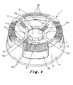
Figure 1 of the drawings appended hereto depicts a top-side elevated perspective view into a preferred embodiment of a plastic top chime according to the present invention. -
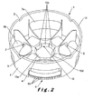
Figure 2 of the drawings appended hereto illustrates an underside, elevated perspective view of a preferred embodiment of a plastic top chime according to the present invention. -
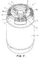
Figure 3 of the drawings is a perspective view of the top chime of the present invention mounted on a complementary keg having a cooperating neck finish. -
Figure 4 of the drawings is a cross-sectional view taken through the top chime according to the present invention, in combination, (i.e. in mounted relation) on a beer keg of the present invention, shown in inter-fitting stacked relation with a complementary top chime of a superposed keg. - Referring in general to
Figures 1 and2 of the appended drawings, there is provided a preferred keg (or container)top chime 1 according to the present invention.Keg top chime 1 comprises a kegneck finish surround 10.Surround 10 is specifically adapted to engage a cooperating keg neck finish (not shown inFigures 1 and2 , but refer instead toFigures 3 and4 ). That engagement sustains a mutually inter-fitting secured relation to thereby at least partially secure the chime to the keg. - In this preferred form of the
chime 1 according to the present invention,surround 10 comprises an opening 10a, which is circumscribed by respectivefree ends 10d of a plurality of resilient,flexible tines 10b. Tines 10b extend radially inwardly into opening 10a, from fixed ends of saidtines 10b that are rooted on a inner, preferablycentral hub 3. - Note that at least one of said
free ends 10d, and preferably a plurality thereof, include atab extension 10c, adapted to engage in corresponding register with a complementary slot (not shown) in a keg neck finish. Although the function of this arrangement could be accomplished in other ways that still fall within the scope of the present invention, (i.e. merely by engaging respective tines in respective individual slots in the neck finish), the tabs are well suited to interfering with any rotation that might otherwise be possible betweenchime 1 and the neck finish, relative to the keg body. -
Chime 1 includes a "spider" 2 for engaging a top portion of a keg body (again, not shown inFigures 1 and2 , refer toFigures 3 and4 and the description that follows below), in surmounted relation bychime 1. Thespider 2 in turn comprises thecentral hub 3 with a plurality of radially outwardly extending legs orspoke girders 4. These spoke girders terminate at arim wall 5, of a downwardly dependingchime skirt 7. -
Spoke girders 4, have channel cross-sections including said walls C that provide a stiffened girder effect and function as support fillets between thecentral hub 3 and thechime skirt 7. - A
handle ring 6 is also arranged to interconnect the radially outmost extent of the spokes, and is spaced above and apart fromchime skirt 7.Handle ring 6 has acurved underside 6a adapted to facilitate hand holds, and a plurality of raisedfins 6b on an opposed surface that function to facilitate hand grips and as a continuation of the supportingsurfaces 6c that form the roots forrespective spoke girders 4 where they join withskirt 7. Additionally, any liquids that fall onto the handle ring is channeled downwardly betweenfins 6b and away from the handhold portion of the chime, to help ensure a non-slippery grip. -
Chime skirt 7 supports aperipheral bead 12 adapted to engage adjacent surfaces of the secured keg body. -
Chime skirt 7 also includeshand holes 7a, positioned below raisedfins 6b, and forming an opening into a "pocket" between the top side of the keg body in between girder side walls C of adjacent pairs of spokes, to thereby permit thehandle ring 6 to be griped from betweenchime 1 and proximal but spaced apart portions of thekeg body top 15a. - Skirt 7 also includes
keg body drains 9 for draining liquids accumulating between theskirt 7 and an associated keg body wall. When in use, keg assemblies according to the present invention can accumulate water or other liquids that would remain trapped between the chime and the keg when the assembly is oriented in its normal upright position, but which is permitted to drain away through thesedrains 9. - Similarly,
handle ring 6 includeschannel drains 11 for draining liquids accumulating within the interior of the girder cross sections ofspokes 4. - Notably, keg assemblies according to the present invention are often washed and filled in an inverted orientation, during which time water might otherwise accumulate unless permitted to drain away through these drains. Note in this connection that the keg of the present invention and assemblies comprising same are preferably closed-system kegs.
- Referring now
Figure 3 thechime 1 is illustrated in mounted relation onkeg body 15. - Note in particular the engagement of
tines 10b with the portion ofkeg neck finish 16 that extends through surround 10 - and in particular, the engagement of the free ends oftines 10b belowneck finish abutment 16b. Also note thatperipheral bead 12 engageskeg body 15 proximal to the transition between the top shoulders and cylindrical or peripheral side wall of the keg. The keg and chime assembly as illustrated inFigure 3 compriseskeg body 15 having a top 15a bearing akeg neck finish 16.Keg top chime 1 comprises a kegneck finish surround 10. The kegtop finish surround 10 and thekeg neck finish 16 are mutually adapted to engage a cooperating, inter-fitting secured relation to thereby at least partially secure said chime and keg in mutually assembled relation. In the variously illustrated embodiments, the inter-fitting secured relation is a resiliently biased mechanically interfering registration between the salient portions ofkeg 15 and saidchime 1. - Referring now to
Figure 4 in particular, there is shown a cut away section through a stacked pair of kegs, illustrating in greater detail the engagement of thechime 1 withkeg body 15, and a complementary stacking relationship ofchime 1 with a top chime of the surmounted keg assembly above it. Although not visible in eitherFigures 3 or4 ,tabs 10c extend into tab receiving mouths located in the neck finish, to secure thechime 1 against rotation relative to thekeg body 15. -
Keg body 15 comprises a shoulder shapedtop 15a extending upwardly from the rest of the kegs cylindrical body. Top 15a has akeg neck finish 16, which is adapted to engage a complementary kegneck finish surround 10 of kegtop chime 1, (also illustrated inFigures 1 and2 ). -
Neck finish 16 includes generallyupstanding side walls 16a extending proud of the adjacent periphery of thekeg body 15 top 15a and terminating in an overhangingannular abutment 16b that is particularly suited to engage in snap-on inter-fitting secured relation with the complementary features oftop chime 1 as described elsewhere herein. -
Spoke girders 4 are curved along edges of side walls C to conform in shape along adjacent surfaces of kegtop portion 15a, to be supported in contacting relation there along. - The resulting
chime 1 is a particularly light weight design, and introduces relatively low material costs to the overall keg assembly. - It is clear that in order to fix a
chime 1 according to the invention to a keg, it suffices to position thechime 1 with theopening 10 over the keg neck finish and to press it down such that the flexible tines snap into the slot in the keg neck finish. - In the case the keg is a plastic keg, it is preferred to provide an internal overpressure in the keg in order to avoid any deformation thereof during fixation of the
chime 1. - For removal of the
chime 1, one can tear of thechime 1, Although the removal can easily be automated by use of a cylindrical drill, breaking thetines 10b, whereby thechime 1 will fall of the keg as are thetines 10b. Such automated and simple removal of the chime obviously simplifies recycling the keg assemblies. - Finally it is remarked that both the keg and the chime can have various forms. The kegs for example can have a circular cross section, a rectangular cross section or a cross section in any other shape.
Claims (9)
- Container assembly comprising a container and a top chime (1) fixed to each other, the container having a top part and a peripheral side wall (15), and the chime comprising:• a substantially central inner hub (3) with fixation means (10),• a plurality of legs (4) extending radially outwardly from the inner hub (3), and terminating in• a rim wall of a skirt (7) whereby the skirt engages the peripheral side wall (15) of said container,characterized in that, the chime (1) is fixed to the top part of the container and at a distance from said peripheral side wall (15) and in that, said fixation means (10) of the inner hub (3) comprises a snap-fit means such that the fixation between the chime and the container is achieved by a snap fit.
- Container assembly according to claim 1, characterized in that the fixation is a releasable fixation.
- Container assembly according to claims 1 or 2, characterized in that the fixation means (10) has a surround that comprises an opening (10a) circumscribed by respective free ends of a plurality of resilient tines (10b) extending radially inwardly from the inner hub (3).
- container assembly according to any of the preceding claims, characterized in that the fixation of the chime to the container is provided at a neck portion (16) of the container.
- A chime suitable for being fixed to a container, said chime comprising:• a substantially central inner hub (3) with fixation means (10),• a plurality of legs (4) extending radially outwardly from the inner hub (3) and terminating in• a rim wall of a skirt (7) whereby the skirt is suitable for engaging the peripheral side wall of said container,characterized in that, the fixation means (10) of the inner hub (3) comprises a snap-fit means being suitable for fixing the chime to the top part of said container.
- Chime according to claim 5, characterized in that said fixation means (10) has a surround that comprises an opening (10a) circumscribed by respective free ends of a plurality of resilient tines (10b) extending radially inwardly from the inner hub (3).
- Chime according to claim 6, characterized in that at least one of said resilient tines (10b) is provided with a tab extension.
- Chime according to any of claims 5 to 7, characterized in that it comprises a handle ring (6) provided with a plurality of raised fins.
- Chime according to any of claims 5 to 8, characterized in that said rim wall spaces apart both a skirt (7) and a handle ring (6).
Applications Claiming Priority (3)
| Application Number | Priority Date | Filing Date | Title |
|---|---|---|---|
| GB0702670A GB2446392A (en) | 2007-02-12 | 2007-02-12 | A Plastic Upper Chime and Keg Assembly for Beverage Kegs |
| GB0724456A GB0724456D0 (en) | 2007-12-14 | 2007-12-14 | Container, chime and assembly of both |
| PCT/EP2008/051689 WO2008098939A1 (en) | 2007-02-12 | 2008-02-12 | Container, chime and assembly of both |
Publications (2)
| Publication Number | Publication Date |
|---|---|
| EP2117942A1 EP2117942A1 (en) | 2009-11-18 |
| EP2117942B1 true EP2117942B1 (en) | 2013-07-31 |
Family
ID=39333090
Family Applications (1)
| Application Number | Title | Priority Date | Filing Date |
|---|---|---|---|
| EP08708920.7A Not-in-force EP2117942B1 (en) | 2007-02-12 | 2008-02-12 | Container, chime and assembly of both |
Country Status (5)
| Country | Link |
|---|---|
| US (1) | US9156583B2 (en) |
| EP (1) | EP2117942B1 (en) |
| BR (1) | BRPI0807473B1 (en) |
| RU (1) | RU2494936C2 (en) |
| WO (1) | WO2008098939A1 (en) |
Families Citing this family (32)
| Publication number | Priority date | Publication date | Assignee | Title |
|---|---|---|---|---|
| RU2494936C2 (en) * | 2007-02-12 | 2013-10-10 | Инбев С.А. | Container, chime and their assembling |
| CA132119S (en) * | 2009-03-11 | 2010-04-01 | Alto Packaging Ltd | Drum |
| US9434505B2 (en) * | 2010-01-26 | 2016-09-06 | Rehrig Pacific Company | Plastic beer keg |
| BE1019342A5 (en) | 2010-05-20 | 2012-06-05 | Dispack Projects Nv | BARREL FROM PLASTIC, METHOD FOR MANUFACTURING THEM, AND RING FOR A BARREL. |
| WO2012007041A1 (en) | 2010-07-15 | 2012-01-19 | Impress Group B.V. | Disposable container with fitting attachment |
| GB2485555B (en) * | 2010-11-17 | 2014-06-04 | Pet Engineering & Services S R L | Stackable container with a top chime |
| GB2490966B (en) | 2011-05-20 | 2013-12-11 | Petainer Lidkoping Ab | Keg support system |
| USD722215S1 (en) * | 2013-08-05 | 2015-02-03 | Pet Engineering & Services S.R.L. | Barrel |
| USD725864S1 (en) * | 2013-08-05 | 2015-03-31 | Pet Engineering & Services S.R.L. | Barrel |
| EP2974999A3 (en) | 2014-06-23 | 2016-04-20 | William P Apps | Plastic beer keg with liner and valve |
| GB2532223B (en) * | 2014-11-11 | 2017-11-15 | Petainer Large Container Ip Ltd | Keg protection assembly |
| USD842579S1 (en) | 2016-09-23 | 2019-03-05 | Silvia Romana Marabini | Barrel |
| US11370579B2 (en) | 2017-02-07 | 2022-06-28 | Ball Corporation | Tapered metal cup and method of forming the same |
| US10875076B2 (en) | 2017-02-07 | 2020-12-29 | Ball Corporation | Tapered metal cup and method of forming the same |
| GB2560024B (en) * | 2017-02-27 | 2020-04-22 | Petainer Large Container Ip Ltd | Keg chime |
| GB201801609D0 (en) * | 2018-01-31 | 2018-03-14 | Pet Eng & Services S R L | Assembly including a container and a chime |
| WO2019195398A1 (en) * | 2018-04-05 | 2019-10-10 | Loucks Timothy James | Container for storing, transporting and dispensing a beverage |
| USD950318S1 (en) | 2018-05-24 | 2022-05-03 | Ball Corporation | Tapered cup |
| USD906056S1 (en) | 2018-12-05 | 2020-12-29 | Ball Corporation | Tapered cup |
| USD967327S1 (en) * | 2019-02-27 | 2022-10-18 | Amtrol Licensing Inc. | Cylinder stand |
| USD968893S1 (en) | 2019-06-24 | 2022-11-08 | Ball Corporation | Tapered cup |
| ES3008479T3 (en) * | 2019-08-14 | 2025-03-24 | Emanuela Covi | Gripping and closing device for a keg type container |
| USD944485S1 (en) * | 2019-12-12 | 2022-02-22 | Polykeg Srl | Container with a slim handle |
| USD953811S1 (en) | 2020-02-14 | 2022-06-07 | Ball Corporation | Tapered cup |
| USD974845S1 (en) | 2020-07-15 | 2023-01-10 | Ball Corporation | Tapered cup |
| MX2023004991A (en) | 2020-10-30 | 2023-07-13 | Ball Corp | Tapered cup and method of forming the same. |
| USD1012617S1 (en) | 2021-02-22 | 2024-01-30 | Ball Corporation | Tapered cup |
| USD1035386S1 (en) | 2021-12-08 | 2024-07-16 | Ball Corporation | Tapered cup |
| USD1064179S1 (en) * | 2022-08-05 | 2025-02-25 | Amtrol Licensing Inc. | Cylinder stand |
| USD1108960S1 (en) | 2023-12-26 | 2026-01-13 | iRoma Scents A.B. Ltd. | Chamber |
| USD1030484S1 (en) | 2023-12-26 | 2024-06-11 | Iromascents A.B. Ltd. | Chamber |
| USD1042882S1 (en) * | 2023-12-26 | 2024-09-17 | Iromascents A.B. Ltd. | Modular drum |
Family Cites Families (32)
| Publication number | Priority date | Publication date | Assignee | Title |
|---|---|---|---|---|
| US1197924A (en) * | 1915-02-02 | 1916-09-12 | Tyson Romaine W | Barrel or keg. |
| US2489766A (en) * | 1946-02-16 | 1949-11-29 | Smith Corp A O | Chime for barrels |
| US3095111A (en) * | 1960-11-04 | 1963-06-25 | Firestone Tire & Rubber Co | Chime structures for barrels |
| US3349940A (en) * | 1964-12-28 | 1967-10-31 | Cornelius Co | Thermally insulated tank |
| US3390807A (en) * | 1964-12-28 | 1968-07-02 | Cornelius Co | Beverage tank assembly |
| NL7305209A (en) * | 1972-04-17 | 1973-10-19 | ||
| US4022345A (en) * | 1976-03-15 | 1977-05-10 | Advanced Chemical Technology | Drum with handling rings |
| US4103806A (en) * | 1977-01-03 | 1978-08-01 | White E Vernon | Valve guard for protecting the regulator valve on a scuba tank |
| US4088239A (en) * | 1977-05-23 | 1978-05-09 | Owens-Illinois, Inc. | Plastic drum and metal handling ring |
| JPS603071Y2 (en) * | 1981-03-05 | 1985-01-28 | サッポロビール株式会社 | Synthetic resin bottle |
| DE3140022A1 (en) | 1981-10-08 | 1983-04-28 | Fissler Gmbh, 6580 Idar-Oberstein | Keg |
| USD277041S (en) * | 1982-06-28 | 1985-01-01 | Hoover Universal, Inc. | Beer keg |
| DE3336681C1 (en) | 1983-10-08 | 1984-12-20 | Hoesch Ag, 4600 Dortmund | Top or bottom ring on drums |
| US4680068A (en) * | 1984-08-06 | 1987-07-14 | Hofstetter Donald R | Method for forming drum handling rings |
| US4867348A (en) * | 1985-05-17 | 1989-09-19 | Adolph Coors Company | Disposable package for use in marketing fluids |
| US4573603A (en) * | 1985-06-03 | 1986-03-04 | Worthington Industries, Inc. | Fluid container |
| DE3602689A1 (en) * | 1986-01-30 | 1987-08-06 | Fissler Gmbh | Drum-like transport container |
| GB8609523D0 (en) * | 1986-04-18 | 1986-05-21 | Alumasc Ltd | Kegs |
| US4907712A (en) * | 1988-09-19 | 1990-03-13 | Stempin David R | Tank stabilizer |
| US5004117A (en) * | 1989-09-25 | 1991-04-02 | Sakae Kitsuda | Safety cylinder cap |
| US5209362A (en) * | 1992-01-24 | 1993-05-11 | Lutzker Robert S | Can resealer |
| US5562219A (en) * | 1994-09-22 | 1996-10-08 | Valois, S.A. | Device for attaching a dispenser member to a receptacle |
| US5709252A (en) * | 1995-06-06 | 1998-01-20 | Progas, Inc. | Natural gas distribution system |
| EP0826604A3 (en) | 1996-08-30 | 2000-03-22 | Rex Articoli Tecnici SA | Container for beverages under pressure |
| US6049945A (en) * | 1998-12-17 | 2000-04-18 | Graham Packaging Company L.P. | Stackable ergonomic handle |
| US6302291B1 (en) * | 1999-03-15 | 2001-10-16 | Mccleerey Paul | Transporting device for beer kegs and propane tanks |
| US6386384B1 (en) * | 2000-02-09 | 2002-05-14 | Amtrol, Inc. | Full jacket gas cylinder |
| US7255245B2 (en) * | 2004-04-23 | 2007-08-14 | Amtrol Inc. | Hybrid pressure vessel with separable jacket |
| TWI350270B (en) | 2005-04-19 | 2011-10-11 | Ecokeg Pty Ltd | Liquid storage and dispensing apparatus |
| RU2470843C2 (en) * | 2007-02-12 | 2012-12-27 | Инбев С.А. | Container and chime, and method of its production |
| RU2494936C2 (en) * | 2007-02-12 | 2013-10-10 | Инбев С.А. | Container, chime and their assembling |
| US8439223B2 (en) * | 2007-08-20 | 2013-05-14 | The Procter & Gamble Company | Base cup for a supportable pressurizable container |
-
2008
- 2008-02-12 RU RU2009134113/12A patent/RU2494936C2/en not_active IP Right Cessation
- 2008-02-12 WO PCT/EP2008/051689 patent/WO2008098939A1/en not_active Ceased
- 2008-02-12 EP EP08708920.7A patent/EP2117942B1/en not_active Not-in-force
- 2008-02-12 US US12/449,489 patent/US9156583B2/en not_active Expired - Fee Related
- 2008-02-12 BR BRPI0807473-9A patent/BRPI0807473B1/en not_active IP Right Cessation
Also Published As
| Publication number | Publication date |
|---|---|
| RU2494936C2 (en) | 2013-10-10 |
| BRPI0807473B1 (en) | 2018-07-03 |
| US20100072212A1 (en) | 2010-03-25 |
| EP2117942A1 (en) | 2009-11-18 |
| US9156583B2 (en) | 2015-10-13 |
| RU2009134113A (en) | 2011-03-20 |
| WO2008098939A1 (en) | 2008-08-21 |
| BRPI0807473A2 (en) | 2014-05-13 |
Similar Documents
| Publication | Publication Date | Title |
|---|---|---|
| US9156583B2 (en) | Container, chime and assembly of both | |
| CN101641262B (en) | Container, chime and assembly of both | |
| EP2130777B1 (en) | Pail with skirt and lid | |
| US6789828B1 (en) | Stabilizing two-bottle carrier | |
| US4194645A (en) | Container cover construction | |
| EP1710171A1 (en) | Balanced multiple container carrier | |
| CA2385881C (en) | Bottle crate | |
| EP2585381B1 (en) | Container with top and bottom chimes | |
| AU667822B2 (en) | Sanitary can carriers | |
| CA2496771A1 (en) | Waste container | |
| AU672085B2 (en) | Stainless steel container | |
| CA2972077C (en) | Nesting container carrier | |
| WO2009033230A1 (en) | Beverage container carrier | |
| US12351358B2 (en) | Container having a stacking feature | |
| EP1958555A1 (en) | Bowl and basket assembly | |
| CA2972081C (en) | Container carrier with flexible flange | |
| US20030136790A1 (en) | Food storage container with easy open feature | |
| EP0322152B1 (en) | A crate | |
| US3095111A (en) | Chime structures for barrels | |
| KR200278075Y1 (en) | Top ring and bottom ring for protect draft beer barrel | |
| NZ735007B (en) | Container carrier with flexible flange | |
| NZ735001B (en) | Nesting container carrier | |
| WO1987006207A1 (en) | Improvements relating to kegs | |
| WO1994012409A1 (en) | Molded plastic container | |
| JP2017013868A (en) | Foam cover for drums |
Legal Events
| Date | Code | Title | Description |
|---|---|---|---|
| PUAI | Public reference made under article 153(3) epc to a published international application that has entered the european phase |
Free format text: ORIGINAL CODE: 0009012 |
|
| 17P | Request for examination filed |
Effective date: 20090817 |
|
| AK | Designated contracting states |
Kind code of ref document: A1 Designated state(s): AT BE BG CH CY CZ DE DK EE ES FI FR GB GR HR HU IE IS IT LI LT LU LV MC MT NL NO PL PT RO SE SI SK TR |
|
| DAX | Request for extension of the european patent (deleted) | ||
| 17Q | First examination report despatched |
Effective date: 20100604 |
|
| TPAC | Observations by third parties |
Free format text: ORIGINAL CODE: EPIDOSNTIPA |
|
| RAP1 | Party data changed (applicant data changed or rights of an application transferred) |
Owner name: ANHEUSER-BUSCH INBEV S.A. |
|
| GRAP | Despatch of communication of intention to grant a patent |
Free format text: ORIGINAL CODE: EPIDOSNIGR1 |
|
| INTG | Intention to grant announced |
Effective date: 20130424 |
|
| GRAS | Grant fee paid |
Free format text: ORIGINAL CODE: EPIDOSNIGR3 |
|
| GRAA | (expected) grant |
Free format text: ORIGINAL CODE: 0009210 |
|
| AK | Designated contracting states |
Kind code of ref document: B1 Designated state(s): AT BE BG CH CY CZ DE DK EE ES FI FR GB GR HR HU IE IS IT LI LT LU LV MC MT NL NO PL PT RO SE SI SK TR |
|
| REG | Reference to a national code |
Ref country code: GB Ref legal event code: FG4D Ref country code: CH Ref legal event code: EP |
|
| REG | Reference to a national code |
Ref country code: AT Ref legal event code: REF Ref document number: 624453 Country of ref document: AT Kind code of ref document: T Effective date: 20130815 |
|
| REG | Reference to a national code |
Ref country code: IE Ref legal event code: FG4D |
|
| REG | Reference to a national code |
Ref country code: DE Ref legal event code: R096 Ref document number: 602008026389 Country of ref document: DE Effective date: 20130926 |
|
| REG | Reference to a national code |
Ref country code: NL Ref legal event code: T3 |
|
| REG | Reference to a national code |
Ref country code: AT Ref legal event code: MK05 Ref document number: 624453 Country of ref document: AT Kind code of ref document: T Effective date: 20130731 |
|
| REG | Reference to a national code |
Ref country code: LT Ref legal event code: MG4D |
|
| PG25 | Lapsed in a contracting state [announced via postgrant information from national office to epo] |
Ref country code: IS Free format text: LAPSE BECAUSE OF FAILURE TO SUBMIT A TRANSLATION OF THE DESCRIPTION OR TO PAY THE FEE WITHIN THE PRESCRIBED TIME-LIMIT Effective date: 20131130 Ref country code: AT Free format text: LAPSE BECAUSE OF FAILURE TO SUBMIT A TRANSLATION OF THE DESCRIPTION OR TO PAY THE FEE WITHIN THE PRESCRIBED TIME-LIMIT Effective date: 20130731 Ref country code: SE Free format text: LAPSE BECAUSE OF FAILURE TO SUBMIT A TRANSLATION OF THE DESCRIPTION OR TO PAY THE FEE WITHIN THE PRESCRIBED TIME-LIMIT Effective date: 20130731 Ref country code: CY Free format text: LAPSE BECAUSE OF FAILURE TO SUBMIT A TRANSLATION OF THE DESCRIPTION OR TO PAY THE FEE WITHIN THE PRESCRIBED TIME-LIMIT Effective date: 20130814 Ref country code: HR Free format text: LAPSE BECAUSE OF FAILURE TO SUBMIT A TRANSLATION OF THE DESCRIPTION OR TO PAY THE FEE WITHIN THE PRESCRIBED TIME-LIMIT Effective date: 20130731 Ref country code: PT Free format text: LAPSE BECAUSE OF FAILURE TO SUBMIT A TRANSLATION OF THE DESCRIPTION OR TO PAY THE FEE WITHIN THE PRESCRIBED TIME-LIMIT Effective date: 20131202 Ref country code: LT Free format text: LAPSE BECAUSE OF FAILURE TO SUBMIT A TRANSLATION OF THE DESCRIPTION OR TO PAY THE FEE WITHIN THE PRESCRIBED TIME-LIMIT Effective date: 20130731 Ref country code: NO Free format text: LAPSE BECAUSE OF FAILURE TO SUBMIT A TRANSLATION OF THE DESCRIPTION OR TO PAY THE FEE WITHIN THE PRESCRIBED TIME-LIMIT Effective date: 20131031 |
|
| PG25 | Lapsed in a contracting state [announced via postgrant information from national office to epo] |
Ref country code: SI Free format text: LAPSE BECAUSE OF FAILURE TO SUBMIT A TRANSLATION OF THE DESCRIPTION OR TO PAY THE FEE WITHIN THE PRESCRIBED TIME-LIMIT Effective date: 20130731 Ref country code: GR Free format text: LAPSE BECAUSE OF FAILURE TO SUBMIT A TRANSLATION OF THE DESCRIPTION OR TO PAY THE FEE WITHIN THE PRESCRIBED TIME-LIMIT Effective date: 20131101 Ref country code: PL Free format text: LAPSE BECAUSE OF FAILURE TO SUBMIT A TRANSLATION OF THE DESCRIPTION OR TO PAY THE FEE WITHIN THE PRESCRIBED TIME-LIMIT Effective date: 20130731 Ref country code: FI Free format text: LAPSE BECAUSE OF FAILURE TO SUBMIT A TRANSLATION OF THE DESCRIPTION OR TO PAY THE FEE WITHIN THE PRESCRIBED TIME-LIMIT Effective date: 20130731 Ref country code: LV Free format text: LAPSE BECAUSE OF FAILURE TO SUBMIT A TRANSLATION OF THE DESCRIPTION OR TO PAY THE FEE WITHIN THE PRESCRIBED TIME-LIMIT Effective date: 20130731 |
|
| PG25 | Lapsed in a contracting state [announced via postgrant information from national office to epo] |
Ref country code: CY Free format text: LAPSE BECAUSE OF FAILURE TO SUBMIT A TRANSLATION OF THE DESCRIPTION OR TO PAY THE FEE WITHIN THE PRESCRIBED TIME-LIMIT Effective date: 20130731 |
|
| PG25 | Lapsed in a contracting state [announced via postgrant information from national office to epo] |
Ref country code: EE Free format text: LAPSE BECAUSE OF FAILURE TO SUBMIT A TRANSLATION OF THE DESCRIPTION OR TO PAY THE FEE WITHIN THE PRESCRIBED TIME-LIMIT Effective date: 20130731 Ref country code: SK Free format text: LAPSE BECAUSE OF FAILURE TO SUBMIT A TRANSLATION OF THE DESCRIPTION OR TO PAY THE FEE WITHIN THE PRESCRIBED TIME-LIMIT Effective date: 20130731 Ref country code: CZ Free format text: LAPSE BECAUSE OF FAILURE TO SUBMIT A TRANSLATION OF THE DESCRIPTION OR TO PAY THE FEE WITHIN THE PRESCRIBED TIME-LIMIT Effective date: 20130731 Ref country code: DK Free format text: LAPSE BECAUSE OF FAILURE TO SUBMIT A TRANSLATION OF THE DESCRIPTION OR TO PAY THE FEE WITHIN THE PRESCRIBED TIME-LIMIT Effective date: 20130731 Ref country code: RO Free format text: LAPSE BECAUSE OF FAILURE TO SUBMIT A TRANSLATION OF THE DESCRIPTION OR TO PAY THE FEE WITHIN THE PRESCRIBED TIME-LIMIT Effective date: 20130731 |
|
| PG25 | Lapsed in a contracting state [announced via postgrant information from national office to epo] |
Ref country code: IT Free format text: LAPSE BECAUSE OF FAILURE TO SUBMIT A TRANSLATION OF THE DESCRIPTION OR TO PAY THE FEE WITHIN THE PRESCRIBED TIME-LIMIT Effective date: 20130731 Ref country code: ES Free format text: LAPSE BECAUSE OF FAILURE TO SUBMIT A TRANSLATION OF THE DESCRIPTION OR TO PAY THE FEE WITHIN THE PRESCRIBED TIME-LIMIT Effective date: 20130731 |
|
| PLBE | No opposition filed within time limit |
Free format text: ORIGINAL CODE: 0009261 |
|
| STAA | Information on the status of an ep patent application or granted ep patent |
Free format text: STATUS: NO OPPOSITION FILED WITHIN TIME LIMIT |
|
| 26N | No opposition filed |
Effective date: 20140502 |
|
| REG | Reference to a national code |
Ref country code: DE Ref legal event code: R097 Ref document number: 602008026389 Country of ref document: DE Effective date: 20140502 |
|
| PG25 | Lapsed in a contracting state [announced via postgrant information from national office to epo] |
Ref country code: MC Free format text: LAPSE BECAUSE OF FAILURE TO SUBMIT A TRANSLATION OF THE DESCRIPTION OR TO PAY THE FEE WITHIN THE PRESCRIBED TIME-LIMIT Effective date: 20130731 Ref country code: LU Free format text: LAPSE BECAUSE OF FAILURE TO SUBMIT A TRANSLATION OF THE DESCRIPTION OR TO PAY THE FEE WITHIN THE PRESCRIBED TIME-LIMIT Effective date: 20140212 |
|
| REG | Reference to a national code |
Ref country code: CH Ref legal event code: PL |
|
| PG25 | Lapsed in a contracting state [announced via postgrant information from national office to epo] |
Ref country code: CH Free format text: LAPSE BECAUSE OF NON-PAYMENT OF DUE FEES Effective date: 20140228 Ref country code: LI Free format text: LAPSE BECAUSE OF NON-PAYMENT OF DUE FEES Effective date: 20140228 |
|
| REG | Reference to a national code |
Ref country code: IE Ref legal event code: MM4A |
|
| PG25 | Lapsed in a contracting state [announced via postgrant information from national office to epo] |
Ref country code: IE Free format text: LAPSE BECAUSE OF NON-PAYMENT OF DUE FEES Effective date: 20140212 |
|
| REG | Reference to a national code |
Ref country code: FR Ref legal event code: PLFP Year of fee payment: 9 |
|
| PG25 | Lapsed in a contracting state [announced via postgrant information from national office to epo] |
Ref country code: MT Free format text: LAPSE BECAUSE OF FAILURE TO SUBMIT A TRANSLATION OF THE DESCRIPTION OR TO PAY THE FEE WITHIN THE PRESCRIBED TIME-LIMIT Effective date: 20130731 |
|
| PG25 | Lapsed in a contracting state [announced via postgrant information from national office to epo] |
Ref country code: BG Free format text: LAPSE BECAUSE OF FAILURE TO SUBMIT A TRANSLATION OF THE DESCRIPTION OR TO PAY THE FEE WITHIN THE PRESCRIBED TIME-LIMIT Effective date: 20130731 |
|
| PG25 | Lapsed in a contracting state [announced via postgrant information from national office to epo] |
Ref country code: HU Free format text: LAPSE BECAUSE OF FAILURE TO SUBMIT A TRANSLATION OF THE DESCRIPTION OR TO PAY THE FEE WITHIN THE PRESCRIBED TIME-LIMIT; INVALID AB INITIO Effective date: 20080212 Ref country code: TR Free format text: LAPSE BECAUSE OF FAILURE TO SUBMIT A TRANSLATION OF THE DESCRIPTION OR TO PAY THE FEE WITHIN THE PRESCRIBED TIME-LIMIT Effective date: 20130731 |
|
| REG | Reference to a national code |
Ref country code: FR Ref legal event code: PLFP Year of fee payment: 10 |
|
| REG | Reference to a national code |
Ref country code: FR Ref legal event code: PLFP Year of fee payment: 11 |
|
| PGFP | Annual fee paid to national office [announced via postgrant information from national office to epo] |
Ref country code: NL Payment date: 20190218 Year of fee payment: 12 |
|
| PGFP | Annual fee paid to national office [announced via postgrant information from national office to epo] |
Ref country code: GB Payment date: 20190218 Year of fee payment: 12 Ref country code: DE Payment date: 20190219 Year of fee payment: 12 |
|
| PGFP | Annual fee paid to national office [announced via postgrant information from national office to epo] |
Ref country code: FR Payment date: 20190220 Year of fee payment: 12 Ref country code: BE Payment date: 20190218 Year of fee payment: 12 |
|
| REG | Reference to a national code |
Ref country code: DE Ref legal event code: R119 Ref document number: 602008026389 Country of ref document: DE |
|
| REG | Reference to a national code |
Ref country code: NL Ref legal event code: MM Effective date: 20200301 |
|
| GBPC | Gb: european patent ceased through non-payment of renewal fee |
Effective date: 20200212 |
|
| REG | Reference to a national code |
Ref country code: BE Ref legal event code: MM Effective date: 20200229 |
|
| PG25 | Lapsed in a contracting state [announced via postgrant information from national office to epo] |
Ref country code: NL Free format text: LAPSE BECAUSE OF NON-PAYMENT OF DUE FEES Effective date: 20200301 |
|
| PG25 | Lapsed in a contracting state [announced via postgrant information from national office to epo] |
Ref country code: DE Free format text: LAPSE BECAUSE OF NON-PAYMENT OF DUE FEES Effective date: 20200901 Ref country code: GB Free format text: LAPSE BECAUSE OF NON-PAYMENT OF DUE FEES Effective date: 20200212 Ref country code: FR Free format text: LAPSE BECAUSE OF NON-PAYMENT OF DUE FEES Effective date: 20200229 |
|
| PG25 | Lapsed in a contracting state [announced via postgrant information from national office to epo] |
Ref country code: BE Free format text: LAPSE BECAUSE OF NON-PAYMENT OF DUE FEES Effective date: 20200229 |