EP2117923B1 - Lining for an aircraft - Google Patents
Lining for an aircraft Download PDFInfo
- Publication number
- EP2117923B1 EP2117923B1 EP08707982.8A EP08707982A EP2117923B1 EP 2117923 B1 EP2117923 B1 EP 2117923B1 EP 08707982 A EP08707982 A EP 08707982A EP 2117923 B1 EP2117923 B1 EP 2117923B1
- Authority
- EP
- European Patent Office
- Prior art keywords
- lining
- cable
- lining panel
- panel
- fuselage cell
- Prior art date
- Legal status (The legal status is an assumption and is not a legal conclusion. Google has not performed a legal analysis and makes no representation as to the accuracy of the status listed.)
- Not-in-force
Links
- 239000004033 plastic Substances 0.000 claims description 12
- 229920003023 plastic Polymers 0.000 claims description 12
- 230000000694 effects Effects 0.000 description 8
- 230000006837 decompression Effects 0.000 description 5
- 238000009423 ventilation Methods 0.000 description 3
- 239000004696 Poly ether ether ketone Substances 0.000 description 2
- 239000004952 Polyamide Substances 0.000 description 2
- 239000004698 Polyethylene Substances 0.000 description 2
- 239000004743 Polypropylene Substances 0.000 description 2
- 238000010276 construction Methods 0.000 description 2
- 239000000463 material Substances 0.000 description 2
- 230000002093 peripheral effect Effects 0.000 description 2
- 230000035699 permeability Effects 0.000 description 2
- 229920002647 polyamide Polymers 0.000 description 2
- 229920002530 polyetherether ketone Polymers 0.000 description 2
- -1 polyethylene Polymers 0.000 description 2
- 229920000573 polyethylene Polymers 0.000 description 2
- 229920001155 polypropylene Polymers 0.000 description 2
- 238000007789 sealing Methods 0.000 description 2
- 239000000725 suspension Substances 0.000 description 2
- 229920001187 thermosetting polymer Polymers 0.000 description 2
- OKTJSMMVPCPJKN-UHFFFAOYSA-N Carbon Chemical compound [C] OKTJSMMVPCPJKN-UHFFFAOYSA-N 0.000 description 1
- 229920002430 Fibre-reinforced plastic Polymers 0.000 description 1
- 229910000831 Steel Inorganic materials 0.000 description 1
- 229910001069 Ti alloy Inorganic materials 0.000 description 1
- 229910045601 alloy Inorganic materials 0.000 description 1
- 239000000956 alloy Substances 0.000 description 1
- 229920003235 aromatic polyamide Polymers 0.000 description 1
- 230000000903 blocking effect Effects 0.000 description 1
- 229910052799 carbon Inorganic materials 0.000 description 1
- 239000000919 ceramic Substances 0.000 description 1
- 239000000835 fiber Substances 0.000 description 1
- 239000011151 fibre-reinforced plastic Substances 0.000 description 1
- 239000003365 glass fiber Substances 0.000 description 1
- 238000012423 maintenance Methods 0.000 description 1
- 229910052751 metal Inorganic materials 0.000 description 1
- 239000002184 metal Substances 0.000 description 1
- 239000002861 polymer material Substances 0.000 description 1
- 239000010959 steel Substances 0.000 description 1
- 229920001169 thermoplastic Polymers 0.000 description 1
- 239000004634 thermosetting polymer Substances 0.000 description 1
Images

Classifications
-
- F—MECHANICAL ENGINEERING; LIGHTING; HEATING; WEAPONS; BLASTING
- F16—ENGINEERING ELEMENTS AND UNITS; GENERAL MEASURES FOR PRODUCING AND MAINTAINING EFFECTIVE FUNCTIONING OF MACHINES OR INSTALLATIONS; THERMAL INSULATION IN GENERAL
- F16B—DEVICES FOR FASTENING OR SECURING CONSTRUCTIONAL ELEMENTS OR MACHINE PARTS TOGETHER, e.g. NAILS, BOLTS, CIRCLIPS, CLAMPS, CLIPS OR WEDGES; JOINTS OR JOINTING
- F16B37/00—Nuts or like thread-engaging members
- F16B37/04—Devices for fastening nuts to surfaces, e.g. sheets, plates
- F16B37/06—Devices for fastening nuts to surfaces, e.g. sheets, plates by means of welding or riveting
- F16B37/062—Devices for fastening nuts to surfaces, e.g. sheets, plates by means of welding or riveting by means of riveting
- F16B37/065—Devices for fastening nuts to surfaces, e.g. sheets, plates by means of welding or riveting by means of riveting by deforming the material of the nut
-
- F—MECHANICAL ENGINEERING; LIGHTING; HEATING; WEAPONS; BLASTING
- F16—ENGINEERING ELEMENTS AND UNITS; GENERAL MEASURES FOR PRODUCING AND MAINTAINING EFFECTIVE FUNCTIONING OF MACHINES OR INSTALLATIONS; THERMAL INSULATION IN GENERAL
- F16B—DEVICES FOR FASTENING OR SECURING CONSTRUCTIONAL ELEMENTS OR MACHINE PARTS TOGETHER, e.g. NAILS, BOLTS, CIRCLIPS, CLAMPS, CLIPS OR WEDGES; JOINTS OR JOINTING
- F16B4/00—Shrinkage connections, e.g. assembled with the parts at different temperature; Force fits; Non-releasable friction-grip fastenings
- F16B4/004—Press fits, force fits, interference fits, i.e. fits without heat or chemical treatment
-
- B—PERFORMING OPERATIONS; TRANSPORTING
- B64—AIRCRAFT; AVIATION; COSMONAUTICS
- B64C—AEROPLANES; HELICOPTERS
- B64C1/00—Fuselages; Constructional features common to fuselages, wings, stabilising surfaces or the like
- B64C2001/009—Fuselages; Constructional features common to fuselages, wings, stabilising surfaces or the like comprising decompression panels or valves for pressure equalisation in fuselages or floors
Definitions
- the invention relates to a lining for a fuselage cell of an aircraft, comprising a multiplicity of lining panels adjoining one another, an intermediate space existing between the fuselage cell and the lining.
- the lining panels must have adequate sound permeability. Furthermore, the lining panels should provide adequate electromagnetic shielding in case the electrical lines within the aircraft do not have adequate shielding. In addition, the lining panels must be adequately isolated from deformations of the fuselage cell, because insufficiently elastic fastening of the panels forming the lining to the fuselage cell causes stresses. The lining panels themselves only withstand a pressure difference of up to 80 hPa. In the case of a sudden drop in pressure in the interior space of the fuselage cell, furthermore, a pressure equalization must be possible through the lining without the panels intruding into the passenger compartment and possibly injuring the passengers. Finally, the lining is also intended to allow adequate compensation for production tolerances.
- Lining panels of this type are produced by sandwich panels, which have, for example, a honeycomb core with outer layers applied to both sides.
- the outer layers are formed with preference by a fibre reinforced thermosetting polymer material, which is provided at least in certain regions with a metal backing, to achieve an adequate electromagnetic shielding effect with at the same time adequate sound permeability.
- the lining panels are usually connected to profiles, which are in turn connected to the fuselage cell by means of mounts.
- the profiles arranged with preference in the manner of a truss, form what is known as the "lining framework".
- the pressuretight sealing between the lining panels and the profiles is performed by peripheral seals.
- the required pressure equalization between the interior space of the fuselage cell and the intermediate space located between the lining and the outer skin of the fuselage cell takes place in the case of a sudden drop in pressure in the interior space of the fuselage cell (known as "rapid decompression") through additional ventilation flaps in the lining.
- Document Us 5 085 017 discloses a lining for a fuselage cell of an aircraft according to the preamble of claim 1.
- the object of the invention is to meet the range of requirements described above for a lining of an aircraft and to dispense with the need for the additional, weight-intensive ventilation flaps of the known embodiments of linings.
- At least one lining panel has such a connection to the fuselage cell that, when there is a rapid drop in pressure between an interior space of the fuselage cell and the intermediate space, at least one lining panel exposes at least one gap to allow pressure equalization means that, in an emergency, automatic pressure equalization can take place between the space inside the fuselage cell and the intermediate space obtained between the lining and the outer skin of the fuselage cell.
- the positive pressure of about 500 hPa that still continues to exist for a short time in the intermediate space has the effect that the at least one lining panel is pressed in the direction of the interior space, exposing gaps for automatic pressure equalization.
- lining panels will be formed in such a way as to achieve a decompression effect that is as uniform as possible over the entire longitudinal extent of the fuselage cell.
- the suspension of the at least one lining panel takes place by means of at least one cable, which leads from two opposite sides of the lining panel to a holding point arranged in the centre of the lining panel and having a predetermined breaking point.
- This refinement makes flexible and weight-saving suspension of the horizontally extending lining panels possible.
- a development of the lining provides that at least one holding point of the lining panel has a predetermined breaking point.
- the predetermined breaking point is formed with preference by a threaded bolt with a screwed-on plastic nut, the thread of which tears away when a critical load-bearing capacity is exceeded and allows the panel to drop downwards, limited by the length of the cable.
- a cable guide for fastening or guiding the cable.
- the plastic nut may be formed, for example, by a thermosetting or thermoplastic polymer material, such as for example by polyethylene (PE), polyamide (PA), polypropylene (PP) or polyetherether ketone (PEEK).
- a thermosetting or thermoplastic polymer material such as for example by polyethylene (PE), polyamide (PA), polypropylene (PP) or polyetherether ketone (PEEK).
- the predetermined breaking point may also be formed by a bolt with a cross section reduced in a locally defined manner, or the like.
- Figure 1 shows a detail from the lining in the normal state, that is to say without the lining panel being lowered.
- a lining 1 of the fuselage cell 2 of an aircraft is formed, inter alia, by three substantially horizontally extending lining panels 3 to 5.
- the lining panels 3 to 5 are formed in a known sandwich type of construction, for example with a honeycomb core and outer layers of a fibre reinforced polymer material applied on both sides.
- the lining 1 produces an intermediate space 6, which is separate from the interior space 7 of the fuselage cell 2 of the aircraft. In the region of the exterior space 8 outside the fuselage cell 2 there prevails an atmospheric pressure corresponding to the altitude of the aircraft at the time of close to 0 hPa.
- a pressure of approximately 500 hPa prevails both in the intermediate space 6 and in the interior space 7 of the aircraft, corresponding to a height of approximately 2000 m above sea level.
- first articulation point 10 In the region of a first edge 9 of the lining panel 4 there is a first articulation point 10. Starting from this first articulation point 10, a cable 11 extends over a first cable guide 12 to a holding point 14 arranged in a central region 13 of the lining panel 4. From there, the cable 11 is led over a second cable guide 15 to a second articulation point 16 in the region of the second edge 17 of the lining panel 4.
- the cable guides 12, 15 are arranged on two supports 18, 19, which can be adjusted in length and are fastened to the fuselage cell 2.
- Four profiles 21 to 24 are fastened on an inner side 20 of the lining panel 4.
- the profiles 21 to 24 are fastened, for example, by screws, rivets, clamping bolts or the like, which are introduced into bushes inserted into the lining panel 4 (known as "inserts"). Seals, which are not represented, may be provided between the profiles 21 to 24 and the inner side 20 of the lining panel 4.
- the profiles 21 and 24 form the two articulation points 10, 16, in which the cable 11 is fastened by means of suitable fittings.
- the supports 18, 19 hold up the lining panel in the region of the profiles 22 and 23.
- the cable 11 is under a prestress, so that, in the normal state that is shown, the lining panel 4 is drawn against the two supports 18, 19 counter to the effect of gravitational force.
- the supports 18, 19 have at the ends V-shaped grooves, which are not designated any more specifically, for respectively receiving profiles 22, 23.
- the profiles 22 and 23 are only under tensile force as they lie in these V-shaped grooves, providing adequate mobility of the lining panel 4 to compensate for deformations of the fuselage cell 2 and production-related tolerances.
- the holding point 14 has a third cable guide 25.
- This is fastened to a threaded bolt 26, which is led through a hole 27 in the central region 13 of the lining panel 4 and onto which, with preference, a plastic nut 28 is screwed to fasten the panel.
- An insert, a bush for leading through the threaded bolt 26, which optionally has a peripheral rim on which the plastic nut can rest, may likewise be provided in the hole 27.
- the plastic nut 28 may have an integrally joined-on annular rest for introducing force and sealing the hole 27 in the lining panel 4.
- the plastic nut 28 forms a predetermined breaking point 30, which ruptures when a critical load-bearing capacity is exceeded. If the pressure in the interior space 7 of the fuselage cell 2 suddenly drops to something in the order of 0 hPa (known as "rapid decompression"), a positive pressure of approximately 500 hPa still continues to prevail for a short time in the intermediate space 6. As a result of this briefly continuing pressure difference, such a high mechanical force acts on the inner side 20 of the lining panel 4 that the critical load-bearing capacity required for defined tearing away of the threads of the plastic nut 28 on the threaded bolt 26 is exceeded and brings about the controlled lowering of the lining panel 4 downwards in the vertical direction by the previously fixed amount. The amount of lowering depends in particular on the length of the cable 11. Within the entire lining 1, a number of lining panels 4 that lower automatically when there is a drop in pressure may be provided.
- the lowering of the lining panel 4 may take place substantially parallel to the horizontal or else only on one side, that is to say the lining panel 4 is pivoted about an imaginary pivot point lying in the region of the first edge 9 and the actual lowering by the predefined amount only takes place in the region of the second edge 17.
- Such an effect can be achieved, for example, by a cable stopper in the region of the first cable guide 12.
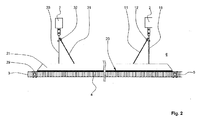
- Figure 2 shows a section through the lining along the sectional line II-II of Figure 1 .
- the lining panel 4 is adjoined on both sides by the lining panels 3, 5.
- the profile 21 extends substantially over the entire inner side 20 of the lining panel 4. Seals, of which only the seal 29 is provided with a reference numeral for the sake of a better overview of the drawing, enclose the panels 3 to 5, with preference on all sides. As a result, a substantially pressuretight termination of the intermediate space 6 is achieved.
- the support 18, which can with preference be adjusted in length, is connected to the fuselage cell 2 and carries the first cable guide 12. In a way corresponding to the path followed by the cable 11 (cf. Figure 1 ), there extends a further cable 31.
- the cable 31 is likewise led over a cable guide 32, which is fastened to a further support 33.
- the support 33 has the same construction as the two (front) supports 18, 19. Behind the support 33 there is, perpendicularly with respect to the plane of the drawing, a further support, which is not represented in Figure 2 but has a cable guide for the cable 31, the structural form of which likewise respectively corresponds to that of the support 18 or the cable guide 12 (cf. Figure 1 ).
- Both cables 11, 31 extend such that they are inclined with respect to the horizontal by an angle of approximately 60°, whereby the lateral guidance of the lining panel 4 in the horizontal is improved.
- the cables 11, 31 are formed by an alloy of a stainless high-grade steel or a titanium alloy.
- high-strength fibres such as for example carbon fibres, glass fibres, aramid fibres, ceramic fibres or the like.
- narrow bands or chains may also be used.
- the lining panel 4 can be easily lowered by unscrewing the plastic nut 28 by an amount fixed by the length of the cables 11, 31, of for example up to 10 cm.
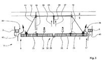
- Figure 3 illustrates the detail from the lining according to Figure 1 in a lowered (decompressed) state.
- the lining panel 4 is lowered downwards in the direction of the arrows 34, 35, the profiles 22, 23 coming away from the shaped recesses or grooves in the supports 18, 19.
- two gaps 38, 39 are opened in relation to the adjacent lining panels 3, 5, with the result of pressure equalization between the interior space 7 and the intermediate space 6, as represented by the dash-dotted arrows 40, 41.
- the lining panel 4 is lowered in relation to the adjacent lining panels 3, 5 by the distances 42, 43. Further lowering of the lining panel 4 does not take place, because the length of the cable 11 is limited. This avoids uncontrolled dropping down of the lining panel 4.
- the gaps 38, 39 dispense with the need for separate, weight-increasing ventilation flaps in the lining 1.
Landscapes
- Engineering & Computer Science (AREA)
- General Engineering & Computer Science (AREA)
- Mechanical Engineering (AREA)
- Laminated Bodies (AREA)
- Connection Of Plates (AREA)
- Casting Or Compression Moulding Of Plastics Or The Like (AREA)
- Body Structure For Vehicles (AREA)
- Lining Or Joining Of Plastics Or The Like (AREA)
Description
- The invention relates to a lining for a fuselage cell of an aircraft, comprising a multiplicity of lining panels adjoining one another, an intermediate space existing between the fuselage cell and the lining.
- Known embodiments of lining panels for the lining of fuselage cells of aircraft, and in particular for use in propeller-powered aeroplanes, must meet a large number of requirements.
- Firstly, the lining panels must have adequate sound permeability. Furthermore, the lining panels should provide adequate electromagnetic shielding in case the electrical lines within the aircraft do not have adequate shielding. In addition, the lining panels must be adequately isolated from deformations of the fuselage cell, because insufficiently elastic fastening of the panels forming the lining to the fuselage cell causes stresses. The lining panels themselves only withstand a pressure difference of up to 80 hPa. In the case of a sudden drop in pressure in the interior space of the fuselage cell, furthermore, a pressure equalization must be possible through the lining without the panels intruding into the passenger compartment and possibly injuring the passengers. Finally, the lining is also intended to allow adequate compensation for production tolerances.
- Lining panels of this type are produced by sandwich panels, which have, for example, a honeycomb core with outer layers applied to both sides. The outer layers are formed with preference by a fibre reinforced thermosetting polymer material, which is provided at least in certain regions with a metal backing, to achieve an adequate electromagnetic shielding effect with at the same time adequate sound permeability. The lining panels are usually connected to profiles, which are in turn connected to the fuselage cell by means of mounts. The profiles, arranged with preference in the manner of a truss, form what is known as the "lining framework". The pressuretight sealing between the lining panels and the profiles is performed by peripheral seals. The required pressure equalization between the interior space of the fuselage cell and the intermediate space located between the lining and the outer skin of the fuselage cell takes place in the case of a sudden drop in pressure in the interior space of the fuselage cell (known as "rapid decompression") through additional ventilation flaps in the lining.
- Document Us 5 085 017 discloses a lining for a fuselage cell of an aircraft according to the preamble of
claim 1. - The object of the invention is to meet the range of requirements described above for a lining of an aircraft and to dispense with the need for the additional, weight-intensive ventilation flaps of the known embodiments of linings.
- This object is achieved by a lining with the features of
Patent Claim 1. - The fact that at least one lining panel has such a connection to the fuselage cell that, when there is a rapid drop in pressure between an interior space of the fuselage cell and the intermediate space, at least one lining panel exposes at least one gap to allow pressure equalization means that, in an emergency, automatic pressure equalization can take place between the space inside the fuselage cell and the intermediate space obtained between the lining and the outer skin of the fuselage cell.
- In the case of a sudden drop in pressure in the interior space to a value of approximately 0 hPa, the positive pressure of about 500 hPa that still continues to exist for a short time in the intermediate space has the effect that the at least one lining panel is pressed in the direction of the interior space, exposing gaps for automatic pressure equalization.
- With preference, a number of lining panels will be formed in such a way as to achieve a decompression effect that is as uniform as possible over the entire longitudinal extent of the fuselage cell.
- In the case of the substantially horizontally extending lining panels, which serve in particular for lining the ceiling of the interior space of the aircraft, the suspension of the at least one lining panel takes place by means of at least one cable, which leads from two opposite sides of the lining panel to a holding point arranged in the centre of the lining panel and having a predetermined breaking point.
- This refinement makes flexible and weight-saving suspension of the horizontally extending lining panels possible.
- A development of the lining provides that at least one holding point of the lining panel has a predetermined breaking point.
- This ensures that, when there is a sufficiently great pressure difference between the interior space and the intermediate space - as occurs when there is a sudden drop in pressure in the interior space of the fuselage cell ("rapid decompression") -, the at least one lining panel is automatically lowered with respect to the adjacent lining panels, and consequently exposes gaps for decompression. The predetermined breaking point is formed with preference by a threaded bolt with a screwed-on plastic nut, the thread of which tears away when a critical load-bearing capacity is exceeded and allows the panel to drop downwards, limited by the length of the cable. Arranged on the threaded bolt is a cable guide for fastening or guiding the cable. The plastic nut may be formed, for example, by a thermosetting or thermoplastic polymer material, such as for example by polyethylene (PE), polyamide (PA), polypropylene (PP) or polyetherether ketone (PEEK). Alternatively, the predetermined breaking point may also be formed by a bolt with a cross section reduced in a locally defined manner, or the like.
- Further advantageous refinements of the lining are presented in the further patent claims.
- In the drawing:
- Figure 1
- shows a side view of a detail from the lining according to the invention with substantially horizontally extending lining panels in the normal state,
- Figure 2
- shows a view of the lining along the sectional line II-II of
Figure 1 , - Figure 3
- shows a side view of the lining according to the invention after pressure equalization has taken place, and
- In the drawing, the same structural elements have in each case the same reference numerals.
-
Figure 1 shows a detail from the lining in the normal state, that is to say without the lining panel being lowered. - A
lining 1 of the fuselage cell 2 of an aircraft is formed, inter alia, by three substantially horizontally extendinglining panels 3 to 5. Thelining panels 3 to 5 are formed in a known sandwich type of construction, for example with a honeycomb core and outer layers of a fibre reinforced polymer material applied on both sides. Thelining 1 produces anintermediate space 6, which is separate from theinterior space 7 of the fuselage cell 2 of the aircraft. In the region of theexterior space 8 outside the fuselage cell 2 there prevails an atmospheric pressure corresponding to the altitude of the aircraft at the time of close to 0 hPa. In the normal operating state of the aircraft, at an altitude of, for example, 10,000 m, a pressure of approximately 500 hPa prevails both in theintermediate space 6 and in theinterior space 7 of the aircraft, corresponding to a height of approximately 2000 m above sea level. - In the region of a first edge 9 of the
lining panel 4 there is afirst articulation point 10. Starting from thisfirst articulation point 10, acable 11 extends over afirst cable guide 12 to aholding point 14 arranged in acentral region 13 of thelining panel 4. From there, thecable 11 is led over asecond cable guide 15 to asecond articulation point 16 in the region of thesecond edge 17 of thelining panel 4. Thecable guides supports profiles 21 to 24 are fastened on aninner side 20 of thelining panel 4. Theprofiles 21 to 24 are fastened, for example, by screws, rivets, clamping bolts or the like, which are introduced into bushes inserted into the lining panel 4 (known as "inserts"). Seals, which are not represented, may be provided between theprofiles 21 to 24 and theinner side 20 of thelining panel 4. Theprofiles articulation points cable 11 is fastened by means of suitable fittings. In addition, the supports 18, 19 hold up the lining panel in the region of theprofiles cable 11 is under a prestress, so that, in the normal state that is shown, thelining panel 4 is drawn against the two supports 18, 19 counter to the effect of gravitational force. To achieve adequate lateral guidance of thelining panel 4, the supports 18, 19 have at the ends V-shaped grooves, which are not designated any more specifically, for respectively receivingprofiles profiles lining panel 4 to compensate for deformations of the fuselage cell 2 and production-related tolerances. - The
holding point 14 has athird cable guide 25. This is fastened to a threadedbolt 26, which is led through ahole 27 in thecentral region 13 of thelining panel 4 and onto which, with preference, aplastic nut 28 is screwed to fasten the panel. An insert, a bush for leading through the threadedbolt 26, which optionally has a peripheral rim on which the plastic nut can rest, may likewise be provided in thehole 27. As an alternative or in addition, theplastic nut 28 may have an integrally joined-on annular rest for introducing force and sealing thehole 27 in thelining panel 4. In the region of the first andsecond edges 9, 17 of thelining panel 4 and at edges of thelining panels seal 29 of which, in the region of the first edge 9 of thelowerable lining panel 4, is provided with a reference numeral as representative of the others. Theseals 29 provide the effect of a largely pressuretight termination between theintermediate space 6 and theinterior space 7. - Acting together with the threaded
bolt 26, theplastic nut 28 forms a predeterminedbreaking point 30, which ruptures when a critical load-bearing capacity is exceeded. If the pressure in theinterior space 7 of the fuselage cell 2 suddenly drops to something in the order of 0 hPa (known as "rapid decompression"), a positive pressure of approximately 500 hPa still continues to prevail for a short time in theintermediate space 6. As a result of this briefly continuing pressure difference, such a high mechanical force acts on theinner side 20 of thelining panel 4 that the critical load-bearing capacity required for defined tearing away of the threads of theplastic nut 28 on the threadedbolt 26 is exceeded and brings about the controlled lowering of thelining panel 4 downwards in the vertical direction by the previously fixed amount. The amount of lowering depends in particular on the length of thecable 11. Within theentire lining 1, a number oflining panels 4 that lower automatically when there is a drop in pressure may be provided. - The lowering of the
lining panel 4 may take place substantially parallel to the horizontal or else only on one side, that is to say thelining panel 4 is pivoted about an imaginary pivot point lying in the region of the first edge 9 and the actual lowering by the predefined amount only takes place in the region of thesecond edge 17. Such an effect can be achieved, for example, by a cable stopper in the region of thefirst cable guide 12. -
Figure 2 shows a section through the lining along the sectional line II-II ofFigure 1 . - The
lining panel 4 is adjoined on both sides by thelining panels profile 21 extends substantially over the entireinner side 20 of thelining panel 4. Seals, of which only theseal 29 is provided with a reference numeral for the sake of a better overview of the drawing, enclose thepanels 3 to 5, with preference on all sides. As a result, a substantially pressuretight termination of theintermediate space 6 is achieved. - The
support 18, which can with preference be adjusted in length, is connected to the fuselage cell 2 and carries thefirst cable guide 12. In a way corresponding to the path followed by the cable 11 (cf.Figure 1 ), there extends afurther cable 31. Thecable 31 is likewise led over a cable guide 32, which is fastened to afurther support 33. Thesupport 33 has the same construction as the two (front) supports 18, 19. Behind thesupport 33 there is, perpendicularly with respect to the plane of the drawing, a further support, which is not represented inFigure 2 but has a cable guide for thecable 31, the structural form of which likewise respectively corresponds to that of thesupport 18 or the cable guide 12 (cf.Figure 1 ). Bothcables lining panel 4 in the horizontal is improved. - With preference, the
cables cables lining panel 4 can be easily lowered by unscrewing theplastic nut 28 by an amount fixed by the length of thecables -
Figure 3 illustrates the detail from the lining according toFigure 1 in a lowered (decompressed) state. - Since a high positive pressure of approximately 500 hPa prevails in the
intermediate space 6 with respect to theinterior space 7 as a result of the drop in pressure, thelining panel 4 of thelining 1 is pressed downwards in the vertical direction by a force F, which acts in the direction of thewhite arrows 34, 35. The predetermined maximum force effect that thepredetermined breaking point 30 in the form of the threadedbolt 26 and theplastic nut 28 can withstand is thereby exceeded, so that the threadedbolt 26 is abruptly pulled out from theplastic nut 28 together with thecable 11, fastened in thethird cable guide 25, in the direction of theblack arrows lining panel 4 is lowered downwards in the direction of thearrows 34, 35, theprofiles supports gaps adjacent lining panels interior space 7 and theintermediate space 6, as represented by the dash-dotted arrows 40, 41. In the decompressed state, thelining panel 4 is lowered in relation to theadjacent lining panels distances lining panel 4 does not take place, because the length of thecable 11 is limited. This avoids uncontrolled dropping down of thelining panel 4. - Alternatively, it is possible, for example, to lower the
lining panel 4 only in the region of thesecond edge 17, while the first edge 9 remains substantially in its position. This can be achieved by a cable clamp being provided in the region of thefirst cable guide 12 and having the effect of blocking the run of thecable 11 through thefirst cable guide 12. - The
gaps lining 1. -
- 1
- lining
- 2
- fuselage cell
- 3
- lining panel
- 4
- lining panel
- 5
- lining panel
- 6
- intermediate space
- 7
- interior space
- 8
- exterior space
- 9
- first edge
- 10
- first articulation point
- 11
- cable
- 12
- first cable guide
- 13
- central region
- 14
- holding point
- 15
- second cable guide
- 16
- second articulation point
- 17
- second edge
- 18
- support
- 19
- support
- 20
- inner side (lining panel)
- 21
- profile
- 22
- profile
- 23
- profile
- 24
- profile
- 25
- third cable guide (holding point)
- 26
- threaded bolt
- 27
- hole
- 28
- plastic nut
- 29
- seal
- 30
- predetermined breaking point
- 31
- cable
- 32
- cable guide
- 33
- support
- 34
- arrow
- 35
- arrow
- 36
- arrow
- 37
- arrow
- 38
- gap
- 39
- gap
- 40
- arrow
- 41
- arrow
- 42
- distance
- 43
- distance
Claims (6)
- Lining (1) for a fuselage cell (2) of an aircraft, comprising a multiplicity of lining panels (3-5, 44, 45, 66) adjoining one another, an intermediate space (6) existing between the fuselage cell (2) and the lining (1), wherein at least one lining panel (3-5, 44, 45, 66) has such a connection to the fuselage cell (2) passing through the intermediate space (6) that, when there is a rapid drop in pressure between an interior space (7) of the fuselage cell (2) and the intermediate space (6), at least one lining panel (3-5, 44, 46, 66) exposes at least one gap (38, 39, 64, 65) to allow pressure equalization, characterized in that the lining panels (3-5) extend substantially horizontally and the connection of the at least one lining panel (3-5) to the fuselage cell (2) takes place by at least one tensioned cable (11, 31), the at least one lining panel (3-5) being supported against at least two supports (18, 19, 33) which can be adjusted in length and are fastened to the fuselage cell (2).
- Lining (1) according to Patent Claim 1, characterized in that, starting from a first articulation point (10) in the region of a first edge (9) of the at least one lining panel (3-5), the cable (11, 31) is led over a first cable guide (12), arranged on the support (18), over at least one holding point (14), fastened in the central region (13) of the lining panel (3-5), and, from the holding point (14), the cable (11, 31) is led further over a second cable guide (15), arranged on the support (19), to a second articulation point (16) in the region of a second edge (17), lying opposite the first edge (9).
- Lining (1) according of Patent Claim 1 or 2, characterized in that the at least one holding point (14) has a predetermined breaking point (30) in such a way that the holding point (14) gives way above a critical load-bearing capacity of the at least one lining panel (3-5).
- Lining (1) according to one of Patent Claims 1 to 3, characterized in that the at least one holding point (14) is formed by a threaded bolt (26) which has a third cable guide (25) and is fastened in particular by means of a plastic nut (28) as a predetermined breaking point (30) in the at least one lining panel (3-5).
- Lining (1) according to one of Patent Claims 1 to 4, characterized in that a length of the at least one cable (11, 31) is dimensioned in such a way that uncontrolled lowering of the at least one lining panel (3-5) is prevented.
- Lining (1) according to one of Patent Claims 1 to 5, characterized in that the lining panels (3-5) have seals in each case along their edges (9, 17) and adjoin one another in a pressuretight manner.
Applications Claiming Priority (3)
| Application Number | Priority Date | Filing Date | Title |
|---|---|---|---|
| US88187007P | 2007-01-23 | 2007-01-23 | |
| DE102007011627A DE102007011627A1 (en) | 2007-01-23 | 2007-03-09 | Interior lining for an aircraft |
| PCT/EP2008/050537 WO2008090084A2 (en) | 2007-01-23 | 2008-01-18 | Lining for an aircraft |
Publications (2)
| Publication Number | Publication Date |
|---|---|
| EP2117923A2 EP2117923A2 (en) | 2009-11-18 |
| EP2117923B1 true EP2117923B1 (en) | 2016-09-14 |
Family
ID=39564036
Family Applications (1)
| Application Number | Title | Priority Date | Filing Date |
|---|---|---|---|
| EP08707982.8A Not-in-force EP2117923B1 (en) | 2007-01-23 | 2008-01-18 | Lining for an aircraft |
Country Status (9)
| Country | Link |
|---|---|
| US (1) | US8490922B2 (en) |
| EP (1) | EP2117923B1 (en) |
| JP (1) | JP2010516550A (en) |
| CN (1) | CN101636315B (en) |
| BR (1) | BRPI0806889A2 (en) |
| CA (1) | CA2672029A1 (en) |
| DE (1) | DE102007011627A1 (en) |
| RU (1) | RU2463206C2 (en) |
| WO (1) | WO2008090084A2 (en) |
Cited By (3)
| Publication number | Priority date | Publication date | Assignee | Title |
|---|---|---|---|---|
| EP4563463A1 (en) | 2023-11-30 | 2025-06-04 | Airbus Operations GmbH | Support element, fixation arrangement, and vehicle comprising same |
| EP4563462A1 (en) | 2023-11-30 | 2025-06-04 | Airbus Operations GmbH | Fixation glove, fixation arrangement, vehicle comprising same, and method for fixing a mounting structure to a support structure |
| EP4717584A1 (en) | 2024-09-25 | 2026-04-01 | AIRBUS Operations GmbH | Fixation assembly, and fixation arrangement for fixing a mounting structure to a support structure, as well as vehicle comprising same |
Families Citing this family (18)
| Publication number | Priority date | Publication date | Assignee | Title |
|---|---|---|---|---|
| DE102007011627A1 (en) | 2007-01-23 | 2008-07-31 | Airbus Deutschland Gmbh | Interior lining for an aircraft |
| AT505901B1 (en) * | 2008-04-02 | 2009-05-15 | Facc Ag | CEILING PANEL FOR THE COVERING OF THE INTERIOR OF VEHICLES |
| DE102009041597B4 (en) | 2009-09-15 | 2018-10-11 | Airbus Operations Gmbh | A ceiling trim of an interior of an aircraft and a method of covering a ceiling of an interior of an aircraft |
| AT510153B1 (en) * | 2010-10-19 | 2012-02-15 | Facc Ag | decompression |
| DE102011011976B4 (en) | 2011-02-22 | 2013-11-14 | Airbus Operations Gmbh | Decompression assembly for an aircraft |
| ES2404946B1 (en) * | 2011-10-21 | 2014-09-02 | Airbus Operations S.L. | AIRCRAFT FUSELAGE RESISTANT TO IMPACT AND TOLERANT TO IMPROVED DAMAGE |
| US9440744B2 (en) | 2013-10-17 | 2016-09-13 | The Boeing Company | Decompression panel assembly and method of equalizing air pressure differential |
| US9233747B2 (en) | 2013-10-25 | 2016-01-12 | The Boeing Company | Decompression panel for use in an aircraft assembly |
| US9566759B2 (en) | 2013-10-25 | 2017-02-14 | The Boeing Company | Decompression panel for use in an aircraft assembly |
| US10071795B2 (en) | 2013-10-25 | 2018-09-11 | The Boeing Company | Clamp device for use with a decompression panel in an aircraft assembly |
| US9499251B2 (en) | 2013-10-25 | 2016-11-22 | The Boeing Company | Decompression panel for use in an aircraft |
| USD817851S1 (en) | 2014-03-28 | 2018-05-15 | The Boeing Company | Decompression panel |
| US10029798B2 (en) * | 2014-03-31 | 2018-07-24 | The Boeing Company | Structure and method for reducing air flow in a wall volume of an aircraft |
| DE102015205939A1 (en) * | 2015-04-01 | 2016-10-06 | Lufthansa Technik Ag | Device for equalizing a pressure difference for an aircraft |
| DE102017208115A1 (en) * | 2017-05-15 | 2018-11-15 | Lufthansa Technik Ag | Device for equalizing a pressure difference for an aircraft |
| US11427346B2 (en) * | 2018-09-28 | 2022-08-30 | Gulfstream Aerospace Corporation | Cable retainer apparatus and method for retaining a cable |
| CN110565827B (en) * | 2019-08-22 | 2024-05-17 | 广东中集建筑制造有限公司 | Anti-seismic assembly and modularized building |
| CN111717374A (en) * | 2020-05-22 | 2020-09-29 | 成都飞机工业(集团)有限责任公司 | Small and medium-sized unmanned aerial vehicle of gasbag landing formula can throw flap structure |
Family Cites Families (24)
| Publication number | Priority date | Publication date | Assignee | Title |
|---|---|---|---|---|
| US3258890A (en) * | 1962-05-28 | 1966-07-05 | Dow Chemical Co | Framed wall construction with blowout panel |
| FR2306877A1 (en) * | 1975-04-11 | 1976-11-05 | Aerospatiale | SAFETY DEVICE AGAINST BRUTAL DECOMPRESSION OF AIRCRAFT BEDS |
| US3938764A (en) * | 1975-05-19 | 1976-02-17 | Mcdonnell Douglas Corporation | Frangible aircraft floor |
| US4033247A (en) * | 1975-12-17 | 1977-07-05 | Mcdonnell Douglas Corporation | Vent structure |
| SU573937A1 (en) * | 1976-05-17 | 1984-01-23 | Предприятие П/Я А-3395 | Device for securing lining panels |
| DE2756726C2 (en) * | 1977-12-20 | 1982-04-08 | Messerschmitt-Bölkow-Blohm GmbH, 8000 München | Device for pressure equalization in an aircraft or spacecraft |
| US4276725A (en) * | 1979-07-12 | 1981-07-07 | Ash John E | Method and apparatus for releasing an elevated pressure developed behind a wall |
| DE3011109C2 (en) * | 1980-03-22 | 1983-01-05 | Vereinigte Flugtechnische Werke Gmbh, 2800 Bremen | Safety device for aircraft |
| JPS62146830U (en) * | 1986-03-11 | 1987-09-17 | ||
| DE3715328C1 (en) * | 1987-05-08 | 1988-08-18 | Messerschmitt Boelkow Blohm | Decompression panel |
| DE4002447C1 (en) | 1990-01-27 | 1991-03-14 | Deutsche Airbus Gmbh, 2103 Hamburg, De | Decompression panel esp. for aircraft - consists of plate which is releasably held in de-compression opening and consists of two inter-strapped plate parts |
| US5137231A (en) * | 1991-04-29 | 1992-08-11 | The Boeing Company | Decompression venting grille for aircraft |
| US5201831A (en) * | 1991-11-15 | 1993-04-13 | Atr International, Inc. | Aircraft interior shell |
| US5222694A (en) * | 1992-08-03 | 1993-06-29 | Atr International, Inc. | Aircraft interior panel noise dampening support brackets |
| US5871178A (en) * | 1996-09-27 | 1999-02-16 | Mcdonnell Douglas Corporation | Decompression panel for aircraft partition |
| US6264141B1 (en) * | 1997-02-19 | 2001-07-24 | Mcdonnell Douglas Corporation | Aircraft decompression protection panel |
| US6029933A (en) * | 1997-08-01 | 2000-02-29 | The Boeing Company | Fire resistant pressure relief panel assembly |
| US6435455B1 (en) * | 1997-08-01 | 2002-08-20 | The Boeing Company | Flow-efficient, static pressure-shielding, fire-resistant decompression panel assembly |
| US6129312A (en) * | 1997-09-26 | 2000-10-10 | The Boeing Company | Aircraft decompression vent assembly |
| US6158690A (en) * | 1998-10-30 | 2000-12-12 | Sikorsky Aircraft Corporation | Cabin interior panel system for reducing noise transmission in an aircraft |
| US6871822B2 (en) * | 2003-04-18 | 2005-03-29 | The Boeing Company | Apparatus and methods of attaching panels to support structures |
| US7007892B2 (en) * | 2004-03-23 | 2006-03-07 | The Boeing Company | Insulating baffle for a floor shear truss |
| US7624732B2 (en) | 2005-10-06 | 2009-12-01 | The Boeing Company | Method and apparatus for extending flight crew's time of useful consciousness after decompression |
| DE102007011627A1 (en) * | 2007-01-23 | 2008-07-31 | Airbus Deutschland Gmbh | Interior lining for an aircraft |
-
2007
- 2007-03-09 DE DE102007011627A patent/DE102007011627A1/en not_active Ceased
-
2008
- 2008-01-18 CN CN2008800029017A patent/CN101636315B/en not_active Expired - Fee Related
- 2008-01-18 US US12/521,240 patent/US8490922B2/en not_active Expired - Fee Related
- 2008-01-18 CA CA002672029A patent/CA2672029A1/en not_active Abandoned
- 2008-01-18 EP EP08707982.8A patent/EP2117923B1/en not_active Not-in-force
- 2008-01-18 JP JP2009546718A patent/JP2010516550A/en active Pending
- 2008-01-18 BR BRPI0806889-5A2A patent/BRPI0806889A2/en not_active IP Right Cessation
- 2008-01-18 WO PCT/EP2008/050537 patent/WO2008090084A2/en not_active Ceased
- 2008-01-18 RU RU2009130306/11A patent/RU2463206C2/en not_active IP Right Cessation
Cited By (3)
| Publication number | Priority date | Publication date | Assignee | Title |
|---|---|---|---|---|
| EP4563463A1 (en) | 2023-11-30 | 2025-06-04 | Airbus Operations GmbH | Support element, fixation arrangement, and vehicle comprising same |
| EP4563462A1 (en) | 2023-11-30 | 2025-06-04 | Airbus Operations GmbH | Fixation glove, fixation arrangement, vehicle comprising same, and method for fixing a mounting structure to a support structure |
| EP4717584A1 (en) | 2024-09-25 | 2026-04-01 | AIRBUS Operations GmbH | Fixation assembly, and fixation arrangement for fixing a mounting structure to a support structure, as well as vehicle comprising same |
Also Published As
| Publication number | Publication date |
|---|---|
| DE102007011627A1 (en) | 2008-07-31 |
| RU2463206C2 (en) | 2012-10-10 |
| EP2117923A2 (en) | 2009-11-18 |
| BRPI0806889A2 (en) | 2014-04-29 |
| CN101636315A (en) | 2010-01-27 |
| WO2008090084A2 (en) | 2008-07-31 |
| WO2008090084A3 (en) | 2008-09-18 |
| WO2008090084B1 (en) | 2008-11-20 |
| RU2009130306A (en) | 2011-02-27 |
| CN101636315B (en) | 2013-04-17 |
| US20100096500A1 (en) | 2010-04-22 |
| CA2672029A1 (en) | 2008-07-31 |
| US8490922B2 (en) | 2013-07-23 |
| JP2010516550A (en) | 2010-05-20 |
Similar Documents
| Publication | Publication Date | Title |
|---|---|---|
| US8490922B2 (en) | Lining for an aircraft | |
| US8444089B2 (en) | Pressure bulkhead and method for subdivision of an aircraft or spacecraft | |
| US20100187358A1 (en) | Decompression device for an aircraft | |
| US8398021B2 (en) | Compliant crown panel for an aircraft | |
| US8449023B2 (en) | Vehicle emergency egress system | |
| EP2021235B1 (en) | Line system arrangement in an aircraft or spacecraft having a fuselage | |
| US20010025903A1 (en) | Monolithic structure with redundant load paths | |
| US20110146686A1 (en) | Autonomous o2 channel extending in the longitudinal direction | |
| CN102369137A (en) | Center fuselage bellows | |
| EP1434713A1 (en) | Overhead luggage container, particularly for airplanes | |
| US8991757B2 (en) | Self-supporting cabin structural segment | |
| EP2200901B1 (en) | Tank for containing a fluid within a chamber | |
| US11427297B2 (en) | Trailing edge for a composite multispar integrated lifting surface and method for manufacturing said trailing edge | |
| US9878770B2 (en) | Aircraft fuselage having burnthrough resistant components | |
| EP3233635A1 (en) | Overhead luggage compartment for aircraft | |
| EP1642825B1 (en) | Injection-molded window panel and related methods | |
| DE102011101303A1 (en) | Impact protection plate for vehicles, in particular aircraft | |
| EP3778379B1 (en) | Nut plate assembly | |
| EP3730284B1 (en) | Composite panel systems and methods | |
| US20180002107A1 (en) | Lightweight flame resistant composite panel and panel attachment system | |
| US20200023935A1 (en) | Door frame stabilization |
Legal Events
| Date | Code | Title | Description |
|---|---|---|---|
| PUAI | Public reference made under article 153(3) epc to a published international application that has entered the european phase |
Free format text: ORIGINAL CODE: 0009012 |
|
| 17P | Request for examination filed |
Effective date: 20090806 |
|
| AK | Designated contracting states |
Kind code of ref document: A2 Designated state(s): AT BE BG CH CY CZ DE DK EE ES FI FR GB GR HR HU IE IS IT LI LT LU LV MC MT NL NO PL PT RO SE SI SK TR |
|
| DAX | Request for extension of the european patent (deleted) | ||
| RIN1 | Information on inventor provided before grant (corrected) |
Inventor name: BENTHIEN, HERMANN Inventor name: LAZAR, RADOSLAW |
|
| RIN1 | Information on inventor provided before grant (corrected) |
Inventor name: BENTHIEN, HERMANN Inventor name: LAZAR, RADOSLAW |
|
| 17Q | First examination report despatched |
Effective date: 20140120 |
|
| GRAP | Despatch of communication of intention to grant a patent |
Free format text: ORIGINAL CODE: EPIDOSNIGR1 |
|
| INTG | Intention to grant announced |
Effective date: 20160615 |
|
| GRAS | Grant fee paid |
Free format text: ORIGINAL CODE: EPIDOSNIGR3 |
|
| GRAA | (expected) grant |
Free format text: ORIGINAL CODE: 0009210 |
|
| AK | Designated contracting states |
Kind code of ref document: B1 Designated state(s): AT BE BG CH CY CZ DE DK EE ES FI FR GB GR HR HU IE IS IT LI LT LU LV MC MT NL NO PL PT RO SE SI SK TR |
|
| REG | Reference to a national code |
Ref country code: GB Ref legal event code: FG4D |
|
| REG | Reference to a national code |
Ref country code: CH Ref legal event code: EP |
|
| REG | Reference to a national code |
Ref country code: IE Ref legal event code: FG4D |
|
| REG | Reference to a national code |
Ref country code: AT Ref legal event code: REF Ref document number: 828643 Country of ref document: AT Kind code of ref document: T Effective date: 20161015 |
|
| REG | Reference to a national code |
Ref country code: DE Ref legal event code: R096 Ref document number: 602008046272 Country of ref document: DE |
|
| REG | Reference to a national code |
Ref country code: LT Ref legal event code: MG4D |
|
| REG | Reference to a national code |
Ref country code: NL Ref legal event code: MP Effective date: 20160914 |
|
| REG | Reference to a national code |
Ref country code: FR Ref legal event code: PLFP Year of fee payment: 10 |
|
| PG25 | Lapsed in a contracting state [announced via postgrant information from national office to epo] |
Ref country code: FI Free format text: LAPSE BECAUSE OF FAILURE TO SUBMIT A TRANSLATION OF THE DESCRIPTION OR TO PAY THE FEE WITHIN THE PRESCRIBED TIME-LIMIT Effective date: 20160914 Ref country code: NO Free format text: LAPSE BECAUSE OF FAILURE TO SUBMIT A TRANSLATION OF THE DESCRIPTION OR TO PAY THE FEE WITHIN THE PRESCRIBED TIME-LIMIT Effective date: 20161214 Ref country code: LT Free format text: LAPSE BECAUSE OF FAILURE TO SUBMIT A TRANSLATION OF THE DESCRIPTION OR TO PAY THE FEE WITHIN THE PRESCRIBED TIME-LIMIT Effective date: 20160914 Ref country code: HR Free format text: LAPSE BECAUSE OF FAILURE TO SUBMIT A TRANSLATION OF THE DESCRIPTION OR TO PAY THE FEE WITHIN THE PRESCRIBED TIME-LIMIT Effective date: 20160914 |
|
| REG | Reference to a national code |
Ref country code: AT Ref legal event code: MK05 Ref document number: 828643 Country of ref document: AT Kind code of ref document: T Effective date: 20160914 |
|
| PG25 | Lapsed in a contracting state [announced via postgrant information from national office to epo] |
Ref country code: NL Free format text: LAPSE BECAUSE OF FAILURE TO SUBMIT A TRANSLATION OF THE DESCRIPTION OR TO PAY THE FEE WITHIN THE PRESCRIBED TIME-LIMIT Effective date: 20160914 Ref country code: SE Free format text: LAPSE BECAUSE OF FAILURE TO SUBMIT A TRANSLATION OF THE DESCRIPTION OR TO PAY THE FEE WITHIN THE PRESCRIBED TIME-LIMIT Effective date: 20160914 Ref country code: GR Free format text: LAPSE BECAUSE OF FAILURE TO SUBMIT A TRANSLATION OF THE DESCRIPTION OR TO PAY THE FEE WITHIN THE PRESCRIBED TIME-LIMIT Effective date: 20161215 Ref country code: ES Free format text: LAPSE BECAUSE OF FAILURE TO SUBMIT A TRANSLATION OF THE DESCRIPTION OR TO PAY THE FEE WITHIN THE PRESCRIBED TIME-LIMIT Effective date: 20160914 Ref country code: LV Free format text: LAPSE BECAUSE OF FAILURE TO SUBMIT A TRANSLATION OF THE DESCRIPTION OR TO PAY THE FEE WITHIN THE PRESCRIBED TIME-LIMIT Effective date: 20160914 |
|
| PG25 | Lapsed in a contracting state [announced via postgrant information from national office to epo] |
Ref country code: EE Free format text: LAPSE BECAUSE OF FAILURE TO SUBMIT A TRANSLATION OF THE DESCRIPTION OR TO PAY THE FEE WITHIN THE PRESCRIBED TIME-LIMIT Effective date: 20160914 Ref country code: RO Free format text: LAPSE BECAUSE OF FAILURE TO SUBMIT A TRANSLATION OF THE DESCRIPTION OR TO PAY THE FEE WITHIN THE PRESCRIBED TIME-LIMIT Effective date: 20160914 |
|
| PG25 | Lapsed in a contracting state [announced via postgrant information from national office to epo] |
Ref country code: CZ Free format text: LAPSE BECAUSE OF FAILURE TO SUBMIT A TRANSLATION OF THE DESCRIPTION OR TO PAY THE FEE WITHIN THE PRESCRIBED TIME-LIMIT Effective date: 20160914 Ref country code: IS Free format text: LAPSE BECAUSE OF FAILURE TO SUBMIT A TRANSLATION OF THE DESCRIPTION OR TO PAY THE FEE WITHIN THE PRESCRIBED TIME-LIMIT Effective date: 20170114 Ref country code: PT Free format text: LAPSE BECAUSE OF FAILURE TO SUBMIT A TRANSLATION OF THE DESCRIPTION OR TO PAY THE FEE WITHIN THE PRESCRIBED TIME-LIMIT Effective date: 20170116 Ref country code: BE Free format text: LAPSE BECAUSE OF FAILURE TO SUBMIT A TRANSLATION OF THE DESCRIPTION OR TO PAY THE FEE WITHIN THE PRESCRIBED TIME-LIMIT Effective date: 20160914 Ref country code: PL Free format text: LAPSE BECAUSE OF FAILURE TO SUBMIT A TRANSLATION OF THE DESCRIPTION OR TO PAY THE FEE WITHIN THE PRESCRIBED TIME-LIMIT Effective date: 20160914 Ref country code: BG Free format text: LAPSE BECAUSE OF FAILURE TO SUBMIT A TRANSLATION OF THE DESCRIPTION OR TO PAY THE FEE WITHIN THE PRESCRIBED TIME-LIMIT Effective date: 20161214 Ref country code: SK Free format text: LAPSE BECAUSE OF FAILURE TO SUBMIT A TRANSLATION OF THE DESCRIPTION OR TO PAY THE FEE WITHIN THE PRESCRIBED TIME-LIMIT Effective date: 20160914 Ref country code: AT Free format text: LAPSE BECAUSE OF FAILURE TO SUBMIT A TRANSLATION OF THE DESCRIPTION OR TO PAY THE FEE WITHIN THE PRESCRIBED TIME-LIMIT Effective date: 20160914 |
|
| PGFP | Annual fee paid to national office [announced via postgrant information from national office to epo] |
Ref country code: GB Payment date: 20170119 Year of fee payment: 10 |
|
| REG | Reference to a national code |
Ref country code: DE Ref legal event code: R097 Ref document number: 602008046272 Country of ref document: DE |
|
| PG25 | Lapsed in a contracting state [announced via postgrant information from national office to epo] |
Ref country code: IT Free format text: LAPSE BECAUSE OF FAILURE TO SUBMIT A TRANSLATION OF THE DESCRIPTION OR TO PAY THE FEE WITHIN THE PRESCRIBED TIME-LIMIT Effective date: 20160914 |
|
| PLBE | No opposition filed within time limit |
Free format text: ORIGINAL CODE: 0009261 |
|
| STAA | Information on the status of an ep patent application or granted ep patent |
Free format text: STATUS: NO OPPOSITION FILED WITHIN TIME LIMIT |
|
| PG25 | Lapsed in a contracting state [announced via postgrant information from national office to epo] |
Ref country code: DK Free format text: LAPSE BECAUSE OF FAILURE TO SUBMIT A TRANSLATION OF THE DESCRIPTION OR TO PAY THE FEE WITHIN THE PRESCRIBED TIME-LIMIT Effective date: 20160914 |
|
| 26N | No opposition filed |
Effective date: 20170615 |
|
| REG | Reference to a national code |
Ref country code: CH Ref legal event code: PL |
|
| PG25 | Lapsed in a contracting state [announced via postgrant information from national office to epo] |
Ref country code: MC Free format text: LAPSE BECAUSE OF FAILURE TO SUBMIT A TRANSLATION OF THE DESCRIPTION OR TO PAY THE FEE WITHIN THE PRESCRIBED TIME-LIMIT Effective date: 20160914 |
|
| PG25 | Lapsed in a contracting state [announced via postgrant information from national office to epo] |
Ref country code: LI Free format text: LAPSE BECAUSE OF NON-PAYMENT OF DUE FEES Effective date: 20170131 Ref country code: CH Free format text: LAPSE BECAUSE OF NON-PAYMENT OF DUE FEES Effective date: 20170131 |
|
| REG | Reference to a national code |
Ref country code: IE Ref legal event code: MM4A |
|
| PG25 | Lapsed in a contracting state [announced via postgrant information from national office to epo] |
Ref country code: SI Free format text: LAPSE BECAUSE OF FAILURE TO SUBMIT A TRANSLATION OF THE DESCRIPTION OR TO PAY THE FEE WITHIN THE PRESCRIBED TIME-LIMIT Effective date: 20160914 Ref country code: LU Free format text: LAPSE BECAUSE OF NON-PAYMENT OF DUE FEES Effective date: 20170118 |
|
| REG | Reference to a national code |
Ref country code: FR Ref legal event code: PLFP Year of fee payment: 11 |
|
| PG25 | Lapsed in a contracting state [announced via postgrant information from national office to epo] |
Ref country code: IE Free format text: LAPSE BECAUSE OF NON-PAYMENT OF DUE FEES Effective date: 20170118 |
|
| GBPC | Gb: european patent ceased through non-payment of renewal fee |
Effective date: 20180118 |
|
| PG25 | Lapsed in a contracting state [announced via postgrant information from national office to epo] |
Ref country code: MT Free format text: LAPSE BECAUSE OF NON-PAYMENT OF DUE FEES Effective date: 20170118 |
|
| PG25 | Lapsed in a contracting state [announced via postgrant information from national office to epo] |
Ref country code: GB Free format text: LAPSE BECAUSE OF NON-PAYMENT OF DUE FEES Effective date: 20180118 |
|
| PG25 | Lapsed in a contracting state [announced via postgrant information from national office to epo] |
Ref country code: HU Free format text: LAPSE BECAUSE OF FAILURE TO SUBMIT A TRANSLATION OF THE DESCRIPTION OR TO PAY THE FEE WITHIN THE PRESCRIBED TIME-LIMIT; INVALID AB INITIO Effective date: 20080118 |
|
| PG25 | Lapsed in a contracting state [announced via postgrant information from national office to epo] |
Ref country code: CY Free format text: LAPSE BECAUSE OF NON-PAYMENT OF DUE FEES Effective date: 20160914 |
|
| PG25 | Lapsed in a contracting state [announced via postgrant information from national office to epo] |
Ref country code: TR Free format text: LAPSE BECAUSE OF FAILURE TO SUBMIT A TRANSLATION OF THE DESCRIPTION OR TO PAY THE FEE WITHIN THE PRESCRIBED TIME-LIMIT Effective date: 20160914 |
|
| PGFP | Annual fee paid to national office [announced via postgrant information from national office to epo] |
Ref country code: DE Payment date: 20200121 Year of fee payment: 13 |
|
| PGFP | Annual fee paid to national office [announced via postgrant information from national office to epo] |
Ref country code: FR Payment date: 20200121 Year of fee payment: 13 |
|
| REG | Reference to a national code |
Ref country code: DE Ref legal event code: R119 Ref document number: 602008046272 Country of ref document: DE |
|
| PG25 | Lapsed in a contracting state [announced via postgrant information from national office to epo] |
Ref country code: FR Free format text: LAPSE BECAUSE OF NON-PAYMENT OF DUE FEES Effective date: 20210131 |
|
| PG25 | Lapsed in a contracting state [announced via postgrant information from national office to epo] |
Ref country code: DE Free format text: LAPSE BECAUSE OF NON-PAYMENT OF DUE FEES Effective date: 20210803 |