EP2117258A1 - Cable length adjustment in hearing aid devices - Google Patents
Cable length adjustment in hearing aid devices Download PDFInfo
- Publication number
- EP2117258A1 EP2117258A1 EP09006187A EP09006187A EP2117258A1 EP 2117258 A1 EP2117258 A1 EP 2117258A1 EP 09006187 A EP09006187 A EP 09006187A EP 09006187 A EP09006187 A EP 09006187A EP 2117258 A1 EP2117258 A1 EP 2117258A1
- Authority
- EP
- European Patent Office
- Prior art keywords
- ite
- cable
- bte
- face plate
- ear
- Prior art date
- Legal status (The legal status is an assumption and is not a legal conclusion. Google has not performed a legal analysis and makes no representation as to the accuracy of the status listed.)
- Ceased
Links
Images
Classifications
-
- H—ELECTRICITY
- H04—ELECTRIC COMMUNICATION TECHNIQUE
- H04R—LOUDSPEAKERS, MICROPHONES, GRAMOPHONE PICK-UPS OR LIKE ACOUSTIC ELECTROMECHANICAL TRANSDUCERS; ELECTRIC HEARING AIDS; PUBLIC ADDRESS SYSTEMS
- H04R25/00—Electric hearing aids
- H04R25/60—Mounting or interconnection of hearing aid parts, e.g. inside tips, housings or to ossicles
-
- H—ELECTRICITY
- H04—ELECTRIC COMMUNICATION TECHNIQUE
- H04R—LOUDSPEAKERS, MICROPHONES, GRAMOPHONE PICK-UPS OR LIKE ACOUSTIC ELECTROMECHANICAL TRANSDUCERS; ELECTRIC HEARING AIDS; PUBLIC ADDRESS SYSTEMS
- H04R25/00—Electric hearing aids
- H04R25/65—Housing parts, e.g. shells, tips or moulds, or their manufacture
-
- H—ELECTRICITY
- H04—ELECTRIC COMMUNICATION TECHNIQUE
- H04R—LOUDSPEAKERS, MICROPHONES, GRAMOPHONE PICK-UPS OR LIKE ACOUSTIC ELECTROMECHANICAL TRANSDUCERS; ELECTRIC HEARING AIDS; PUBLIC ADDRESS SYSTEMS
- H04R2225/00—Details of deaf aids covered by H04R25/00, not provided for in any of its subgroups
- H04R2225/021—Behind the ear [BTE] hearing aids
- H04R2225/0213—Constructional details of earhooks, e.g. shape, material
-
- H—ELECTRICITY
- H04—ELECTRIC COMMUNICATION TECHNIQUE
- H04R—LOUDSPEAKERS, MICROPHONES, GRAMOPHONE PICK-UPS OR LIKE ACOUSTIC ELECTROMECHANICAL TRANSDUCERS; ELECTRIC HEARING AIDS; PUBLIC ADDRESS SYSTEMS
- H04R2225/00—Details of deaf aids covered by H04R25/00, not provided for in any of its subgroups
- H04R2225/021—Behind the ear [BTE] hearing aids
- H04R2225/0216—BTE hearing aids having a receiver in the ear mould
-
- H—ELECTRICITY
- H04—ELECTRIC COMMUNICATION TECHNIQUE
- H04R—LOUDSPEAKERS, MICROPHONES, GRAMOPHONE PICK-UPS OR LIKE ACOUSTIC ELECTROMECHANICAL TRANSDUCERS; ELECTRIC HEARING AIDS; PUBLIC ADDRESS SYSTEMS
- H04R2225/00—Details of deaf aids covered by H04R25/00, not provided for in any of its subgroups
- H04R2225/57—Aspects of electrical interconnection between hearing aid parts
-
- H—ELECTRICITY
- H04—ELECTRIC COMMUNICATION TECHNIQUE
- H04R—LOUDSPEAKERS, MICROPHONES, GRAMOPHONE PICK-UPS OR LIKE ACOUSTIC ELECTROMECHANICAL TRANSDUCERS; ELECTRIC HEARING AIDS; PUBLIC ADDRESS SYSTEMS
- H04R25/00—Electric hearing aids
- H04R25/60—Mounting or interconnection of hearing aid parts, e.g. inside tips, housings or to ossicles
- H04R25/607—Mounting or interconnection of hearing aid parts, e.g. inside tips, housings or to ossicles of earhooks
-
- H—ELECTRICITY
- H04—ELECTRIC COMMUNICATION TECHNIQUE
- H04R—LOUDSPEAKERS, MICROPHONES, GRAMOPHONE PICK-UPS OR LIKE ACOUSTIC ELECTROMECHANICAL TRANSDUCERS; ELECTRIC HEARING AIDS; PUBLIC ADDRESS SYSTEMS
- H04R25/00—Electric hearing aids
- H04R25/60—Mounting or interconnection of hearing aid parts, e.g. inside tips, housings or to ossicles
- H04R25/609—Mounting or interconnection of hearing aid parts, e.g. inside tips, housings or to ossicles of circuitry
-
- H—ELECTRICITY
- H04—ELECTRIC COMMUNICATION TECHNIQUE
- H04R—LOUDSPEAKERS, MICROPHONES, GRAMOPHONE PICK-UPS OR LIKE ACOUSTIC ELECTROMECHANICAL TRANSDUCERS; ELECTRIC HEARING AIDS; PUBLIC ADDRESS SYSTEMS
- H04R25/00—Electric hearing aids
- H04R25/65—Housing parts, e.g. shells, tips or moulds, or their manufacture
- H04R25/652—Ear tips; Ear moulds
Definitions
- the present invention relates to the correct adjustment of cables for auditory devices.
- a certain category of hearing aid users are best assisted using a combination of hardware components for the ear which is being treated.
- a sound processor device typically including one or more microphones, is provided in a behind the ear (BTE) device.
- BTE behind the ear
- a receiver unit is then provided in the ear canal, either partially or totally in the canal, in order to provide amplified acoustic stimulation for the user.
- the receiver is conventionally connected to the BTE device using an electrical cable which passes over or under the ear and then into the receiver.
- a BTE device is provided, which is electrically connected via a cable to the receiver in the ear canal.
- the BTE device provides sound processing and outputs an electrical signal to the receiver via the cable.
- ITE device is intended to encompass a device which is wholly or partially within the ear canal, whether for a cochlear implant system, hearing aid, or other hearing prosthesis.
- An electro-acoustic system is commercially provided under the Duet brand by Advanced Bionics Corporation (ABC).
- ABS Advanced Bionics Corporation
- the receiver is integrated into the BTE device.
- the acoustic connection between the BTE device and the ear canal is a sound pipe for channelling the acoustic signals - the acoustic signals are generated within the BTE device.
- a BTE device is electrically connected to a receiver in the ear
- the cable is the part of the system which is typically most vulnerable to damage.
- an S shaped cable is used to provide some degree of adjustment and accommodation between the receiver and the BTE device. This allows for a small number of standard lengths of cable, and earhook combinations, to be used for all users.
- the present invention provides an arrangement in which the cable between the ITE and BTE can be adjusted to suit a particular user, so as to achieve an optimal cable length.
- the present invention provides an ITE device; adapted for connection to a cable from a BTE device, the ITE device including a releasable mechanical retention device for the cable, such that the cable may be customised in length and may be attached to the retention device.
- the present invention provides a hearing prosthesis assembly, including a BTE device, an ITE device and a cable electrically connecting them, the ITE device including a releasable mechanical retention device for retaining said cable.
- the present invention provides a method of fitting a hearing prosthesis, the prosthesis including a BTE device, an ITE device and a cable, the method including at least the steps of:
- the ergonomic fit of the BTE device and the ITE can be optimised for each individual recipient during the fitting of the device until the recipient is fully satisfied.
- Suitable embodiments of the present invention allow the cable to be tuned to the correct length and rotation, thereby avoiding tensions between the components and allowing the cable to have a beneficial impact on recipient comfort and BTE retention.
- the ear imprint making and the ITE device production processes are simplified, and the risk for errors in the integration of the cable into the custom moulding is greatly reduced.
- the present invention will be described with reference to a particular illustrative example, which is a device intended for use in a hybrid electrical and acoustic stimulation system.
- a cable is used to connect a BTE device to an ITE device. It may be applied to a cochlear implant system such as a hybrid electrical/acoustic system, a hearing aid system, or any other suitable hearing prosthesis. It may be applied to a system with implanted components, or a fully external system.
- the ITE device may be acoustic only, or may include other functions, for example electrical or communications components. It will be appreciated that the present implementation is described for illustrative purposes, and its features are not intended to be limitative of the scope of the present invention. Many variations and additions are possible within the scope of the present invention.
- Receiver in the ear (RITE) units are already manufactured for hearing aid and hybrid system use. Enabling the RITE manufacturer to build a perfectly fitting RITE using conventional techniques requires the ear imprint maker to provide an accurate indication of the desired cable length, as well as a good estimation of the future level of the face plate, as well as a correct indication of the cable entry point and entry angle. The RITE manufacturer then has to be able to accurately implement this information in his digital 3D RITE design file. Any changes or variations or production errors or recipients' changes of mind require the entire process to be started from scratch.
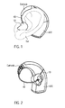
- FIG. 1 An illustrative implementation of the present invention will be described with reference to the general arrangement shown in figures 1 and 2 .
- a BTE device rests behind the pinna, with the earhook extending over the top of the pinna.
- a cable extends from the BTE device, directly into the ITE device.
- This is constructed according to prior art techniques, however, the principle of how the device is positioned in use can be seen.
- the shape and angle of the ear canal vary widely, as do the relative angles of the canal and the pinna.
- there is a huge variation in the shape, angle and dimensions of the pinna As such, it is not practical to have a single cable length. Even using a small set of standard cable sizes, or changeable earhook/cable combinations, will result in significant mis-matches for some users.
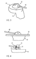
- the BTE device is attached to an earhook (this may be integral or changeable in different implementations), and the cable extends from the earhook to the ITE.
- the BTE unit includes a battery pack, microphones, and processing means as required. The specific electrical functionality of the BTE device is not important to the present invention and will not be further discussed.
- the ITE device includes a receiver, the driving electrical signals for which are provided by the BTE device.
- the combination of the earhook and ITE is described here as a permanent assembly, however, as an alternative an electrical connector could be provided on the ITE Face plate for de-coupling them. This provides enhanced servicing flexibility.
- the illustrative device consists of an SP12 BTE SP (Sound Processor) plus an acoustic ITE unit. These devices are commercially supplied by the applicant.
- the ITE is connected to the BTE device via an electrical cable running through the earhook.
- Correctly selecting the length of the cable is important for several reasons.
- a neat cable is visually discreet and more aesthetically pleasing.
- One of the major reasons for rejection of hearing aids, and especially BTE devices, is a lack of cosmetic acceptability.
- the combined assembly has a more homogenous appearance, and blends into the shape of the pinna in a less visible way.
- a further issue with BTE devices is that in some cases they can be quite heavy, and hence uncomfortable for the user.
- a cable of incorrect length or orientation can exacerbate this, by introducing tensions between the BTE and the ITE component. It is also important the cable has the correct stiffness characteristics to avoid this outcome.
- a stiff or semi-stiff cable can provide significant benefit in keeping the BTE in place and reducing the pressure on the pinna, but only when it is very closely matched to length and rotation. Any mismatch will create difficulties.
- a particularly advantageous outcome of a cable of correct length and placement is that via the cable, the ITE can bear part of the weight of the BTE device and assist in retention of the assembly as a whole.
- the ITE component according to this implementation is assembled from two main elements: a made-to-measure plastic part (called the earshell) fitting exactly in the ear canal of the individual recipient, and a standard front part (the face plate). During the ITE production process the face plate is permanently glued to the earshell and then manually finished to its final contour.
- a made-to-measure plastic part called the earshell
- the face plate is permanently glued to the earshell and then manually finished to its final contour.
- the earshell is preferably custom manufactured from a mould of the user's ear. This process may be the same as that used to form a conventional ITE device, and will accordingly not be described in detail.
- the earshell so produced needs to have an exposed surface suitable for connection to the face plate.
- the electrical cable enters the ITE via the face plate and is connected to a small speaker (the receiver, not visible).
- the receiver is a pre-assembled unit.
- the system allowing adjustment of the cable length and allowing the cable to be locked into the correct position is integrated into the ITE face plate.
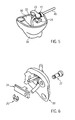
- Figure 3 shows the assembled ITE device 10 of an embodiment of the present invention. It includes the face plate 20, earshell 30 affixed thereto, and the cable 40 extending from the device. It can be seen from the top part of figure 4 that the face plate initially extends beyond the perimeter of the earshell. It is affixed using an adhesive or the like, cut to its final contour and rounded off and finished to match the shape of the earshell.
- the cable adjustment and fixation system is located in the ITE face plate and can best be seen in general from figures 4 and 5 .
- Cable 40 passes through a grommet 41 and into ITE device 10. It is noted that the face plate itself has been removed from part of figure 4 , 5 and 7 to assist with explanation.
- the ITE device 10 the earshell 30 can include a space 50 for storing excess cable after length adjustment.
- Cable 40 is soldered to the receiver in the ITE (not shown on the picture). It has sufficient length to allow it to be positioned without tensioning the soldering contacts. Cable 40 may also be connected to the receiver in the ITE device 10 by a releasable connector. Similarly, a releasable connector can also be used for connecting the cable with the BTE device.
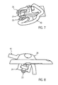
- Cable 40 enters face plate 20 via a rubber grommet 41 for sealing purposes and for protecting cable 40 against internal breaking by it being bent too sharply or similar hazards. Cable 40 then passes over the clamp 24 that will ultimately lock it in place by clamping it against the internal surface of face plate 20. Clamp 24 in its open position allows the cable to move freely during the adjustment process, and when it is tensioned by screw 22 it locks cable 40 into position.
- the locking system can be designed in many variations on the described mechanical design. Variations can be with or without a locking screw.
- the locking system could also allow only one-way cable adjustability freedom: only allowing lengthening the cable (or only shortening it) during the fitting process before locking it.
- the cable fixation system can be simplified to a more basic solution of entering the ITE through an opening, such as the grommet, and fixing it with a sealant. This solution is simple, small and strong. Furthermore it seals the cable to the grommet in a hygienic and watertight way.
- Circlip 25 on the edge of the screw prevents accidental removal of the screw and losing the correct position of the clamp.
- a second Circlip 26 can be foreseen for preventing damage to the cable by overstressing it, one such arrangement can be seen in figure 7 .
- a flexible cover 23 finishes and seals the screw opening.
- FIGS 6 , 8 , 9A and 9B illustrate in more detail the construction of this implementation of the invention.
- the assembly including the screw 22, face plate 20, clamp 24 and circlip 25 can be more readily understood from these drawings.
- the face plate, cable and cable adjustment components are pre-assembled via the electric cable to the earhook with an integrated connector.
- the present invention provides flexibility during the initial fitting on the recipient's ear.
- the recipient can experience the comfort of the assembly prosthesis, and can provide real-time feedback for cable length corrections to be made by the audiologist during the fitting session. This ensures that the optimal length and orientation can be obtained.
- the embodiment described is meant to be used for adjustment by the audiologist at the time of fitting, after which it is fixed into position. However, later adjustments may be required, and an implementation to more readily facilitate this may be foreseen. Similarly, whilst this adjustment is preferably made by the audiologist, some adjustment accessible by the user could be provided.
- the face plate can have a sufficiently small contour to be integrated in the front side of the custom earshell without having to be finished manually, or with minimal finishing. This would reduce the ITE production effort and would allow easier and faster servicing.
- the face plate could be designed such that it can be rotated around its axis for extra fitting freedom for the audiologist during the fitting session. When fixing the cable in its final position, this rotation would also be fixed.
- the face plate could be designed such that it is snapped into the ITE earshell and can later be removed, possibly by using a specific tool. This would allow simplified and more standardised production, cleaning comfort for the recipient and dramatically facilitated servicing even including electronics replacements by the recipient.
- the receiver component can be integrated in a sub-housing that is in its own turn integrated into the customised earshell.
- the integration of the receiver in its own housing provides a customised end result starting from a maximally standardised technical functional unit that can be entirely produced in series and tested. This concept is being used by several hearing aid companies.
- the grommet at the cable entry point on the ITE can be executed such that it provides more protection against sharp bends, or even includes a small finger grip for easy removal of the ITE from the ear.
Landscapes
- Engineering & Computer Science (AREA)
- Health & Medical Sciences (AREA)
- General Health & Medical Sciences (AREA)
- Neurosurgery (AREA)
- Otolaryngology (AREA)
- Physics & Mathematics (AREA)
- Acoustics & Sound (AREA)
- Signal Processing (AREA)
- Manufacturing & Machinery (AREA)
- Prostheses (AREA)
- Headphones And Earphones (AREA)
Abstract
Description
- The present invention relates to the correct adjustment of cables for auditory devices.
- A certain category of hearing aid users are best assisted using a combination of hardware components for the ear which is being treated. A sound processor device, typically including one or more microphones, is provided in a behind the ear (BTE) device. A receiver unit is then provided in the ear canal, either partially or totally in the canal, in order to provide amplified acoustic stimulation for the user. The receiver is conventionally connected to the BTE device using an electrical cable which passes over or under the ear and then into the receiver.
- It has been recognised that, for some users, the combination of a cochlear implant with acoustic stimulation in the same ear has significant benefits. In some such arrangements, a BTE device is provided, which is electrically connected via a cable to the receiver in the ear canal. The BTE device provides sound processing and outputs an electrical signal to the receiver via the cable.
- The term ITE device is intended to encompass a device which is wholly or partially within the ear canal, whether for a cochlear implant system, hearing aid, or other hearing prosthesis.
- An electro-acoustic system is commercially provided under the Duet brand by Advanced Bionics Corporation (ABC). In this device, the receiver is integrated into the BTE device. The acoustic connection between the BTE device and the ear canal is a sound pipe for channelling the acoustic signals - the acoustic signals are generated within the BTE device.
-
US Patent Nos. 6748094 ,7020298 and7142926 , all assigned to ABC, describe the connection of the connection of the earhook to a BTE sound processor via different types of electro-mechanical connectors. - One issue with all such arrangements, in which a BTE device is electrically connected to a receiver in the ear, relates to the connecting cable. It is important to appreciate that the device is worn more or less constantly by the user and so issues such as comfort and cosmetic appeal are very important. The cable is the part of the system which is typically most vulnerable to damage. In many BTE hearing aid systems, an S shaped cable is used to provide some degree of adjustment and accommodation between the receiver and the BTE device. This allows for a small number of standard lengths of cable, and earhook combinations, to be used for all users.
- It is an object of the present invention to provide a BTE device having an electrically connected receiver which has improved comfort and aesthetics.
- Broadly, the present invention provides an arrangement in which the cable between the ITE and BTE can be adjusted to suit a particular user, so as to achieve an optimal cable length.
- According to one aspect, the present invention provides an ITE device; adapted for connection to a cable from a BTE device, the ITE device including a releasable mechanical retention device for the cable, such that the cable may be customised in length and may be attached to the retention device.
- According to another aspect, the present invention provides a hearing prosthesis assembly, including a BTE device, an ITE device and a cable electrically connecting them, the ITE device including a releasable mechanical retention device for retaining said cable.
- According to a further aspect, the present invention provides a method of fitting a hearing prosthesis, the prosthesis including a BTE device, an ITE device and a cable, the method including at least the steps of:
- a) providing a BTE device having a cable attached and a face plate unit;
- b) forming an earshell specifically adapted for a user's ear;
- c) fitting the earshell to the face plate to form an ITE device;
- d) adjusting the cable length using the BTE device and ITE device fitted on the user; and
- e) mechanically securing the cable in position with a retention means in the ITE device.
- By adjusting the cable length, the ergonomic fit of the BTE device and the ITE can be optimised for each individual recipient during the fitting of the device until the recipient is fully satisfied. Suitable embodiments of the present invention allow the cable to be tuned to the correct length and rotation, thereby avoiding tensions between the components and allowing the cable to have a beneficial impact on recipient comfort and BTE retention. The ear imprint making and the ITE device production processes are simplified, and the risk for errors in the integration of the cable into the custom moulding is greatly reduced.
- Illustrative embodiments of the present invention will now be described with reference to the accompanying figures, in which:
-
Figure 1 is a drawing showing a fitted prior art BTE and receiver combination; -
Figure 2 is a schematic view of an assembled device according to the present invention; -
Figure 3 is a view of a face plate assembly; -
Figure 4 is a partly internal view of the face plate assembly offigure 3 ; -
Figure 5 is a view showing the internal components of the face plate assembly positioned on the ear shell; -
Figure 6 is a detailed view of the face plate and clamp mechanism; -
Figure 7 is a view illustrating the operation of an alternative structure for the clamp; -
Figure 8 is a detailed side view of an assembly corresponding tofigure 6 ; and -
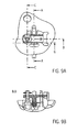
Figures 9A and 9B show an assembled bottom view and a sectional view along line B-B of the assembly offigure 8 . - The present invention will be described with reference to a particular illustrative example, which is a device intended for use in a hybrid electrical and acoustic stimulation system. However, it will be appreciated that the present invention is applicable wherever a cable is used to connect a BTE device to an ITE device. It may be applied to a cochlear implant system such as a hybrid electrical/acoustic system, a hearing aid system, or any other suitable hearing prosthesis. It may be applied to a system with implanted components, or a fully external system. The ITE device may be acoustic only, or may include other functions, for example electrical or communications components. It will be appreciated that the present implementation is described for illustrative purposes, and its features are not intended to be limitative of the scope of the present invention. Many variations and additions are possible within the scope of the present invention.
- Receiver in the ear (RITE) units are already manufactured for hearing aid and hybrid system use. Enabling the RITE manufacturer to build a perfectly fitting RITE using conventional techniques requires the ear imprint maker to provide an accurate indication of the desired cable length, as well as a good estimation of the future level of the face plate, as well as a correct indication of the cable entry point and entry angle. The RITE manufacturer then has to be able to accurately implement this information in his digital 3D RITE design file. Any changes or variations or production errors or recipients' changes of mind require the entire process to be started from scratch.
- An illustrative implementation of the present invention will be described with reference to the general arrangement shown in
figures 1 and 2 . As can be seen infigure 1 , a BTE device rests behind the pinna, with the earhook extending over the top of the pinna. A cable extends from the BTE device, directly into the ITE device. This is constructed according to prior art techniques, however, the principle of how the device is positioned in use can be seen. There are very considerable differences between people in the detailed anatomy of their outer ear and pinna. The shape and angle of the ear canal vary widely, as do the relative angles of the canal and the pinna. Similarly, there is a huge variation in the shape, angle and dimensions of the pinna. As such, it is not practical to have a single cable length. Even using a small set of standard cable sizes, or changeable earhook/cable combinations, will result in significant mis-matches for some users. - As can be seen from
figure 2 , the BTE device is attached to an earhook (this may be integral or changeable in different implementations), and the cable extends from the earhook to the ITE. The BTE unit includes a battery pack, microphones, and processing means as required. The specific electrical functionality of the BTE device is not important to the present invention and will not be further discussed. It is noted that the ITE device includes a receiver, the driving electrical signals for which are provided by the BTE device. - The combination of the earhook and ITE is described here as a permanent assembly, however, as an alternative an electrical connector could be provided on the ITE Face plate for de-coupling them. This provides enhanced servicing flexibility.
- The illustrative device consists of an SP12 BTE SP (Sound Processor) plus an acoustic ITE unit. These devices are commercially supplied by the applicant. The ITE is connected to the BTE device via an electrical cable running through the earhook.
- Correctly selecting the length of the cable is important for several reasons. A neat cable is visually discreet and more aesthetically pleasing. One of the major reasons for rejection of hearing aids, and especially BTE devices, is a lack of cosmetic acceptability. When a cable is correctly fitted in accordance with this implementation of the present invention, the combined assembly has a more homogenous appearance, and blends into the shape of the pinna in a less visible way.
- A further issue with BTE devices is that in some cases they can be quite heavy, and hence uncomfortable for the user. A cable of incorrect length or orientation can exacerbate this, by introducing tensions between the BTE and the ITE component. It is also important the cable has the correct stiffness characteristics to avoid this outcome. A stiff or semi-stiff cable can provide significant benefit in keeping the BTE in place and reducing the pressure on the pinna, but only when it is very closely matched to length and rotation. Any mismatch will create difficulties. However, a particularly advantageous outcome of a cable of correct length and placement is that via the cable, the ITE can bear part of the weight of the BTE device and assist in retention of the assembly as a whole.
- The ITE component according to this implementation is assembled from two main elements: a made-to-measure plastic part (called the earshell) fitting exactly in the ear canal of the individual recipient, and a standard front part (the face plate). During the ITE production process the face plate is permanently glued to the earshell and then manually finished to its final contour.
- The earshell is preferably custom manufactured from a mould of the user's ear. This process may be the same as that used to form a conventional ITE device, and will accordingly not be described in detail. The earshell so produced needs to have an exposed surface suitable for connection to the face plate.
- The electrical cable enters the ITE via the face plate and is connected to a small speaker (the receiver, not visible). The receiver is a pre-assembled unit. The system allowing adjustment of the cable length and allowing the cable to be locked into the correct position is integrated into the ITE face plate.
-
Figure 3 shows the assembledITE device 10 of an embodiment of the present invention. It includes theface plate 20, earshell 30 affixed thereto, and thecable 40 extending from the device. It can be seen from the top part offigure 4 that the face plate initially extends beyond the perimeter of the earshell. It is affixed using an adhesive or the like, cut to its final contour and rounded off and finished to match the shape of the earshell. - The cable adjustment and fixation system is located in the ITE face plate and can best be seen in general from
figures 4 and5 .Cable 40 passes through agrommet 41 and intoITE device 10. It is noted that the face plate itself has been removed from part offigure 4 ,5 and7 to assist with explanation.
As can be seen inFig. 5 and 6 , theITE device 10 theearshell 30 can include aspace 50 for storing excess cable after length adjustment. -
Cable 40 is soldered to the receiver in the ITE (not shown on the picture). It has sufficient length to allow it to be positioned without tensioning the soldering contacts.
Cable 40 may also be connected to the receiver in theITE device 10 by a releasable connector. Similarly, a releasable connector can also be used for connecting the cable with the BTE device. -
Cable 40 entersface plate 20 via arubber grommet 41 for sealing purposes and for protectingcable 40 against internal breaking by it being bent too sharply or similar hazards.Cable 40 then passes over theclamp 24 that will ultimately lock it in place by clamping it against the internal surface offace plate 20.Clamp 24 in its open position allows the cable to move freely during the adjustment process, and when it is tensioned byscrew 22 it lockscable 40 into position. - It will be appreciated that there are many suitable alternative structures which could provide the necessary mechanical retention. The locking system can be designed in many variations on the described mechanical design. Variations can be with or without a locking screw. The locking system could also allow only one-way cable adjustability freedom: only allowing lengthening the cable (or only shortening it) during the fitting process before locking it. The cable fixation system can be simplified to a more basic solution of entering the ITE through an opening, such as the grommet, and fixing it with a sealant. This solution is simple, small and strong. Furthermore it seals the cable to the grommet in a hygienic and watertight way.
-
Circlip 25 on the edge of the screw prevents accidental removal of the screw and losing the correct position of the clamp. Optionally, asecond Circlip 26 can be foreseen for preventing damage to the cable by overstressing it, one such arrangement can be seen infigure 7 . Aflexible cover 23 finishes and seals the screw opening. -
Figures 6 ,8 ,9A and 9B illustrate in more detail the construction of this implementation of the invention. The assembly including thescrew 22,face plate 20,clamp 24 andcirclip 25 can be more readily understood from these drawings. - The face plate, cable and cable adjustment components are pre-assembled via the electric cable to the earhook with an integrated connector.
- The present invention provides flexibility during the initial fitting on the recipient's ear. The recipient can experience the comfort of the assembly prosthesis, and can provide real-time feedback for cable length corrections to be made by the audiologist during the fitting session. This ensures that the optimal length and orientation can be obtained.
- The embodiment described is meant to be used for adjustment by the audiologist at the time of fitting, after which it is fixed into position. However, later adjustments may be required, and an implementation to more readily facilitate this may be foreseen. Similarly, whilst this adjustment is preferably made by the audiologist, some adjustment accessible by the user could be provided.
- In one alternative implementation, the face plate can have a sufficiently small contour to be integrated in the front side of the custom earshell without having to be finished manually, or with minimal finishing. This would reduce the ITE production effort and would allow easier and faster servicing.
- As another alternative, the face plate could be designed such that it can be rotated around its axis for extra fitting freedom for the audiologist during the fitting session. When fixing the cable in its final position, this rotation would also be fixed.
- As another alternative, the face plate could be designed such that it is snapped into the ITE earshell and can later be removed, possibly by using a specific tool. This would allow simplified and more standardised production, cleaning comfort for the recipient and dramatically facilitated servicing even including electronics replacements by the recipient.
- The receiver component can be integrated in a sub-housing that is in its own turn integrated into the customised earshell. The integration of the receiver in its own housing provides a customised end result starting from a maximally standardised technical functional unit that can be entirely produced in series and tested. This concept is being used by several hearing aid companies.
- The illustrative process above describes the earhook plus cable plus ITE face plate plus receiver as a pre-assembled unit to be integrated on the customised ITE. However, solutions can be such that the cable is to be cut and stripped to length during the ITE manufacturing process. This adds the possibility to remove and replace the combined cable and earhook in case of electrical problems. A removable cable will require opening the ITE and soldering the receiver at the ITE manufacturing plant.
- The grommet at the cable entry point on the ITE can be executed such that it provides more protection against sharp bends, or even includes a small finger grip for easy removal of the ITE from the ear.
Claims (13)
- An In-The-Ear (ITE) device (10), adapted for connection to a cable (40) from a Behind-The-Ear (BTE) device, the ITE device (10) including a releasable mechanical retention device for the cable (40), such that the cable (40) may be customised in length and may be attached to the retention device.
- The ITE device (10) according to claim 1, wherein the retention device is releasable.
- The ITE device (10) according to claim 1 or 2, wherein the retention device is a clamp arrangement.
- The ITE device (10) according to claim 1, 2 or 3, wherein the ITE device (10) is formed from a face plate (20) and an earshell (30), the earshell (30) being specifically formed for each user, the face plate (20) being a standard size and wherein the retention device is integrated in the face plate (20).
- The ITE device (10) according to any one of the claims 1 - 4, wherein the face plate (20) is designed such that it can be rotated relative to the earshell (30) around its axis and such that this rotation can be fixed.
- The ITE device (10) according to any one of the claims 1 - 5, wherein the face plate (20) is designed to releasably snap into the ITE earshell (30).
- The ITE device (10) according to any one of the claims 1 - 6, wherein retention device comprises a screw (22) for fixing a clamp (24) at the face plate (20) counter fixed by a circlip (25).
- The ITE device (10) according to any one of the claims 1 - 7, wherein the earshell (30) includes a space (50) for storing excess cable after length adjustment.
- The ITE device (10) according to any one of the claims 1 - 8, wherein the ITE device (10) includes a releasable connector for electrically connecting the cable (40) with the ITE device (10).
- A hearing prosthesis assembly, including a Behind-The-Ear (BTE) device, an In-The-Ear (ITE) device (10) according to any one of the claims 1 - 9, wherein a cable (40) electrically connects them, the ITE device (10) including a releasable mechanical retention device for retaining said cable (40).
- The hearing prosthesis according to claim 10, wherein the cable (40) extends directly from an earhook of the BTE device to the ITE device (10), such that the ITE device (10) and the cable (40) assist in supporting the BTE device.
- The hearing prosthesis according to claim 10 or 11, wherein the ITE device (10) includes a portion which is custom fitted for a user so as to properly fit within at least part of the ear canal of the user.
- A method of fitting a hearing prosthesis, the prosthesis including a Behind-The-Ear (BTE) device, an In-The-Ear (ITE) device (10) and a cable (40), the method including at least the steps of:a) providing the BTE device having a cable (40) attached, and a face plate unit (20);b) forming an earshell (30) specifically adapted for a user's ear;c) fitting the earshell (30) to the face plate (20) to form the ITE device (10);d) adjusting the cable length using the BTE device and ITE device (10) fitted on the user; ande) mechanically securing the cable (40) in position with a retention means in the ITE device (10).
Applications Claiming Priority (1)
| Application Number | Priority Date | Filing Date | Title |
|---|---|---|---|
| AU2008902232A AU2008902232A0 (en) | 2008-05-07 | Cable Length Adjustment in Audio Devices |
Publications (1)
| Publication Number | Publication Date |
|---|---|
| EP2117258A1 true EP2117258A1 (en) | 2009-11-11 |
Family
ID=40902161
Family Applications (1)
| Application Number | Title | Priority Date | Filing Date |
|---|---|---|---|
| EP09006187A Ceased EP2117258A1 (en) | 2008-05-07 | 2009-05-06 | Cable length adjustment in hearing aid devices |
Country Status (2)
| Country | Link |
|---|---|
| US (2) | US8396238B2 (en) |
| EP (1) | EP2117258A1 (en) |
Cited By (3)
| Publication number | Priority date | Publication date | Assignee | Title |
|---|---|---|---|---|
| US8150527B2 (en) | 2004-04-02 | 2012-04-03 | Advanced Bionics, Llc | Electric and acoustic stimulation fitting systems and methods |
| WO2014146702A1 (en) * | 2013-03-20 | 2014-09-25 | Widex A/S | Behind the ear hearing aid |
| US20240114300A1 (en) * | 2022-09-30 | 2024-04-04 | Knowles Electronics, Llc | In-ear hearing device with cable assembly |
Families Citing this family (7)
| Publication number | Priority date | Publication date | Assignee | Title |
|---|---|---|---|---|
| EP2117258A1 (en) | 2008-05-07 | 2009-11-11 | Cochlear Limited | Cable length adjustment in hearing aid devices |
| EP2587839B1 (en) | 2011-10-25 | 2018-03-07 | Oticon A/S | A hearing aid retainer accessory |
| USD712881S1 (en) * | 2013-05-24 | 2014-09-09 | Qualcomm Incorporated | Earpiece |
| USD825764S1 (en) * | 2017-07-03 | 2018-08-14 | Enrique Gajstut | Sound amplifier |
| US12225357B2 (en) * | 2021-08-31 | 2025-02-11 | Starkey Laboratories, Inc. | Cable alignment features in a custom-fitted hearing device shell |
| US11850067B1 (en) * | 2022-05-27 | 2023-12-26 | OpenBCI, Inc. | Multi-purpose ear apparatus for measuring electrical signal from an ear |
| USD982561S1 (en) * | 2023-01-09 | 2023-04-04 | Shenzhen Shengling Technology Co., Ltd | Earphone |
Citations (8)
| Publication number | Priority date | Publication date | Assignee | Title |
|---|---|---|---|---|
| US2863005A (en) * | 1956-10-24 | 1958-12-02 | Sonotone Corp | Magnetic insert earphone and inserts therefor |
| DE2721469A1 (en) * | 1977-05-12 | 1978-11-16 | Siemens Ag | Behind ear carried hearing aid - has conductors in form of coated foil or strip of arbitrary cross=section |
| US4727582A (en) * | 1984-03-23 | 1988-02-23 | U.S. Philips Corporation | Hearing aid with adjustable flexible connection member |
| US6748094B1 (en) | 2000-03-03 | 2004-06-08 | Advanced Bionics Corporation | Connector system for BTE hearing devices |
| DE202006006851U1 (en) * | 2006-04-28 | 2006-07-06 | As Audio Service Gmbh | Ear piece for hearing aid, has connecting unit at end of sound tube, where connecting unit is formed such that unit is insertable together with sound tube into receptacle, and tube held in receptacle in inserted condition |
| US20060159298A1 (en) * | 2005-01-14 | 2006-07-20 | Von Dombrowski Sven | Hearing instrument |
| US7110562B1 (en) * | 2001-08-10 | 2006-09-19 | Hear-Wear Technologies, Llc | BTE/CIC auditory device and modular connector system therefor |
| US7142926B2 (en) | 2002-08-30 | 2006-11-28 | Advanced Bionics Corporation | Quick connect earhook system for BTE devices |
Family Cites Families (12)
| Publication number | Priority date | Publication date | Assignee | Title |
|---|---|---|---|---|
| FR2334382A1 (en) * | 1975-12-11 | 1977-07-08 | Salomon & Fils F | SAFETY BINDING FOR SKI |
| US4827525A (en) * | 1988-04-13 | 1989-05-02 | Minnesota Mining And Manufacturing Company | Attachment device for a probe microphone |
| US5814095A (en) * | 1996-09-18 | 1998-09-29 | Implex Gmbh Spezialhorgerate | Implantable microphone and implantable hearing aids utilizing same |
| JP2003535528A (en) * | 2000-06-01 | 2003-11-25 | オートロジックス エルエルシー | Method and apparatus for measuring the performance of an implantable middle ear hearing aid |
| EP1448015B1 (en) * | 2003-02-14 | 2013-05-22 | GN ReSound A/S | An adaptor for mounting a sound tube in an earpiece |
| JP4966304B2 (en) * | 2005-08-01 | 2012-07-04 | ジーエヌ リザウンド エー/エス | Listening device with open ear pads with short vents |
| DE102005036849A1 (en) * | 2005-08-04 | 2007-02-22 | Siemens Audiologische Technik Gmbh | Receiver tube with damping element and corresponding hearing device |
| US7715580B2 (en) * | 2006-03-21 | 2010-05-11 | Widex A/S | Interchangeable attachment means for attaching a conductor to a hearing aid |
| US20070286442A1 (en) * | 2006-06-13 | 2007-12-13 | Phonak Ag | Method of manufacturing a custom shaped hearing instrument |
| US20090041279A1 (en) * | 2007-08-08 | 2009-02-12 | Davis John W | Acoustic ear tube retainer spring |
| EP2253149A2 (en) * | 2008-03-17 | 2010-11-24 | Phonak AG | Locking mechanism for adjustable tube |
| EP2117258A1 (en) | 2008-05-07 | 2009-11-11 | Cochlear Limited | Cable length adjustment in hearing aid devices |
-
2009
- 2009-05-06 EP EP09006187A patent/EP2117258A1/en not_active Ceased
- 2009-05-07 US US12/437,052 patent/US8396238B2/en not_active Expired - Fee Related
-
2013
- 2013-02-13 US US13/766,750 patent/US8958589B2/en not_active Expired - Fee Related
Patent Citations (9)
| Publication number | Priority date | Publication date | Assignee | Title |
|---|---|---|---|---|
| US2863005A (en) * | 1956-10-24 | 1958-12-02 | Sonotone Corp | Magnetic insert earphone and inserts therefor |
| DE2721469A1 (en) * | 1977-05-12 | 1978-11-16 | Siemens Ag | Behind ear carried hearing aid - has conductors in form of coated foil or strip of arbitrary cross=section |
| US4727582A (en) * | 1984-03-23 | 1988-02-23 | U.S. Philips Corporation | Hearing aid with adjustable flexible connection member |
| US6748094B1 (en) | 2000-03-03 | 2004-06-08 | Advanced Bionics Corporation | Connector system for BTE hearing devices |
| US7020298B1 (en) | 2000-03-03 | 2006-03-28 | Advanced Bionics Corporation | Connector system |
| US7110562B1 (en) * | 2001-08-10 | 2006-09-19 | Hear-Wear Technologies, Llc | BTE/CIC auditory device and modular connector system therefor |
| US7142926B2 (en) | 2002-08-30 | 2006-11-28 | Advanced Bionics Corporation | Quick connect earhook system for BTE devices |
| US20060159298A1 (en) * | 2005-01-14 | 2006-07-20 | Von Dombrowski Sven | Hearing instrument |
| DE202006006851U1 (en) * | 2006-04-28 | 2006-07-06 | As Audio Service Gmbh | Ear piece for hearing aid, has connecting unit at end of sound tube, where connecting unit is formed such that unit is insertable together with sound tube into receptacle, and tube held in receptacle in inserted condition |
Cited By (6)
| Publication number | Priority date | Publication date | Assignee | Title |
|---|---|---|---|---|
| US8150527B2 (en) | 2004-04-02 | 2012-04-03 | Advanced Bionics, Llc | Electric and acoustic stimulation fitting systems and methods |
| US8155747B2 (en) | 2004-04-02 | 2012-04-10 | Advanced Bionics, Llc | Electric and acoustic stimulation fitting systems and methods |
| WO2014146702A1 (en) * | 2013-03-20 | 2014-09-25 | Widex A/S | Behind the ear hearing aid |
| US9860651B2 (en) | 2013-03-20 | 2018-01-02 | Widex A/S | Behind the ear hearing aid |
| US20240114300A1 (en) * | 2022-09-30 | 2024-04-04 | Knowles Electronics, Llc | In-ear hearing device with cable assembly |
| US12309553B2 (en) * | 2022-09-30 | 2025-05-20 | Knowles Electronics, Llc | In-ear hearing device with cable assembly |
Also Published As
| Publication number | Publication date |
|---|---|
| US20100086161A1 (en) | 2010-04-08 |
| US8958589B2 (en) | 2015-02-17 |
| US8396238B2 (en) | 2013-03-12 |
| US20130216080A1 (en) | 2013-08-22 |
Similar Documents
| Publication | Publication Date | Title |
|---|---|---|
| US8958589B2 (en) | Cable length adjustment in auditory devices | |
| AU2006344906B2 (en) | Housing for a hearing aid, hearing aid, and a method of preparing a hearing aid | |
| US7844065B2 (en) | Hearing instrument | |
| US8855347B2 (en) | Hearing device with a vent extension and method for manufacturing such a hearing device | |
| DK1994794T3 (en) | Hearing aid with connecting means for attachment to the outer ear | |
| US20220201413A1 (en) | Hybrid shell for hearing aid | |
| KR101515337B1 (en) | Method of manufacturing a soft custom ear mold and a soft custom ear mold | |
| US8116493B2 (en) | Method of preparing a hearing aid, and a hearing aid | |
| DK2654322T3 (en) | A hearing instrument with the sound tube connector | |
| EP2107827A2 (en) | Hearing aid to be carried in the auricle with individual moulded part | |
| EP2432255A2 (en) | Hearing instrument | |
| WO2010147554A1 (en) | Hearing aid with a replaceable insertion cap | |
| AU2013383006B2 (en) | Behind the ear hearing aid | |
| US10674282B2 (en) | Safety ear hook apparatus | |
| WO2010099581A1 (en) | Adjustmentof components in audio devices |
Legal Events
| Date | Code | Title | Description |
|---|---|---|---|
| PUAI | Public reference made under article 153(3) epc to a published international application that has entered the european phase |
Free format text: ORIGINAL CODE: 0009012 |
|
| 17P | Request for examination filed |
Effective date: 20090506 |
|
| AK | Designated contracting states |
Kind code of ref document: A1 Designated state(s): AT BE BG CH CY CZ DE DK EE ES FI FR GB GR HR HU IE IS IT LI LT LU LV MC MK MT NL NO PL PT RO SE SI SK TR |
|
| RIN1 | Information on inventor provided before grant (corrected) |
Inventor name: BLAETTLER, OLIVIER Inventor name: HUNKELER, THOMAS Inventor name: SLOBODAN, ILIC Inventor name: STALLARD, PHILLIP |
|
| 17Q | First examination report despatched |
Effective date: 20100609 |
|
| STAA | Information on the status of an ep patent application or granted ep patent |
Free format text: STATUS: THE APPLICATION HAS BEEN REFUSED |
|
| 18R | Application refused |
Effective date: 20141004 |