EP2117180A1 - A short range, uni-directional wireless link - Google Patents
A short range, uni-directional wireless link Download PDFInfo
- Publication number
- EP2117180A1 EP2117180A1 EP08103848A EP08103848A EP2117180A1 EP 2117180 A1 EP2117180 A1 EP 2117180A1 EP 08103848 A EP08103848 A EP 08103848A EP 08103848 A EP08103848 A EP 08103848A EP 2117180 A1 EP2117180 A1 EP 2117180A1
- Authority
- EP
- European Patent Office
- Prior art keywords
- master
- signal
- slave
- slave device
- control signal
- Prior art date
- Legal status (The legal status is an assumption and is not a legal conclusion. Google has not performed a legal analysis and makes no representation as to the accuracy of the status listed.)
- Granted
Links
Images


Classifications
-
- H—ELECTRICITY
- H04—ELECTRIC COMMUNICATION TECHNIQUE
- H04W—WIRELESS COMMUNICATION NETWORKS
- H04W84/00—Network topologies
- H04W84/18—Self-organising networks, e.g. ad-hoc networks or sensor networks
-
- H—ELECTRICITY
- H04—ELECTRIC COMMUNICATION TECHNIQUE
- H04R—LOUDSPEAKERS, MICROPHONES, GRAMOPHONE PICK-UPS OR LIKE ACOUSTIC ELECTROMECHANICAL TRANSDUCERS; ELECTRIC HEARING AIDS; PUBLIC ADDRESS SYSTEMS
- H04R25/00—Electric hearing aids
- H04R25/55—Electric hearing aids using an external connection, either wireless or wired
- H04R25/552—Binaural
-
- H—ELECTRICITY
- H04—ELECTRIC COMMUNICATION TECHNIQUE
- H04R—LOUDSPEAKERS, MICROPHONES, GRAMOPHONE PICK-UPS OR LIKE ACOUSTIC ELECTROMECHANICAL TRANSDUCERS; ELECTRIC HEARING AIDS; PUBLIC ADDRESS SYSTEMS
- H04R25/00—Electric hearing aids
- H04R25/55—Electric hearing aids using an external connection, either wireless or wired
- H04R25/554—Electric hearing aids using an external connection, either wireless or wired using a wireless connection, e.g. between microphone and amplifier or using Tcoils
-
- H—ELECTRICITY
- H04—ELECTRIC COMMUNICATION TECHNIQUE
- H04W—WIRELESS COMMUNICATION NETWORKS
- H04W84/00—Network topologies
- H04W84/18—Self-organising networks, e.g. ad-hoc networks or sensor networks
- H04W84/20—Leader-follower arrangements
-
- H—ELECTRICITY
- H04—ELECTRIC COMMUNICATION TECHNIQUE
- H04R—LOUDSPEAKERS, MICROPHONES, GRAMOPHONE PICK-UPS OR LIKE ACOUSTIC ELECTROMECHANICAL TRANSDUCERS; ELECTRIC HEARING AIDS; PUBLIC ADDRESS SYSTEMS
- H04R2225/00—Details of deaf aids covered by H04R25/00, not provided for in any of its subgroups
- H04R2225/55—Communication between hearing aids and external devices via a network for data exchange
-
- Y—GENERAL TAGGING OF NEW TECHNOLOGICAL DEVELOPMENTS; GENERAL TAGGING OF CROSS-SECTIONAL TECHNOLOGIES SPANNING OVER SEVERAL SECTIONS OF THE IPC; TECHNICAL SUBJECTS COVERED BY FORMER USPC CROSS-REFERENCE ART COLLECTIONS [XRACs] AND DIGESTS
- Y02—TECHNOLOGIES OR APPLICATIONS FOR MITIGATION OR ADAPTATION AGAINST CLIMATE CHANGE
- Y02D—CLIMATE CHANGE MITIGATION TECHNOLOGIES IN INFORMATION AND COMMUNICATION TECHNOLOGIES [ICT], I.E. INFORMATION AND COMMUNICATION TECHNOLOGIES AIMING AT THE REDUCTION OF THEIR OWN ENERGY USE
- Y02D30/00—Reducing energy consumption in communication networks
- Y02D30/70—Reducing energy consumption in communication networks in wireless communication networks
Definitions
- a payload signal' is in the present context taken to mean a signal containing information of a specific kind or utility (a 'desired signal'), e.g. 'audio' or 'video' (the term is used to separate its contents from control signals and the like).
- a payload signal is a continuous signal.
- a payload signal is a realtime signal, such as an audio signal that is continuously produced by a source.
- the master device comprises an audio selection device for selecting an audio signal among a multitude of audio signals and forwarding the selected signal to the slave device.
- the master device comprises a remote control device for setting particular parameters of the slave device.
- the system is adapted to optimize the wireless link to function properly when the distance between the locations of the master and slave devices is smaller than a certain maximum BAN-distance, e.g. smaller than 2 m, such as smaller than 1.5 m, such as smaller than 1 m, such as smaller than 0.6 m, such as smaller than 0.5 m.
- the system is adapted to optimize the wireless link to function properly when the distance between the locations of the master and slave devices is in the range from 0.1 m to 2 m, such as 0.2 m to 1.5 m.
- the term 'function properly' can e.g. be based on achieving a transmission with a maximum predefined average bit error rate at a predefined transmission bit rate (e.g. determined by measurement prior to the intended use of the system).
- the inductive coupling between the master device and the slave device is optimized to a predefined frequency range, e.g. by adapting the number of turns, the values of a capacitor and/or a resistor of a resonance circuit formed by the coil, the capacitor and/or the resistor to provide a specific preferred frequency range for the inductive communication.
- Such optimization is preferably performed for each of the coil circuits of the involved master and slave devices.
- the communication between the master device and the slave device may in principle be in any frequency range, e.g. in the RF-range.
- the preferred range is in the MHz-range (e.g. in the range between 1 MHz and 30 MHz or between 10 MHz and 100 MHz).
- the linking procedure between master and slave is based on the identification of a predefined security key in the slave device corresponding to a predefined security key of the master device, e.g. in the form of a number of encrypted or non-encrypted bits.
- the complexity of the security key can advantageously be adapted to the level of security of the application in question.
- a master and a slave device are said to be paired or matched, for example if they have been provided with corresponding security keys.
- the system is adapted to provide that the control signal(s) form(s) part of the packets of status signals. In a particular embodiment, the system is adapted to provide that the security key forms part of the packets of status signals.
- a status packet is attached to every payload data packet, or to every second data packet or to every 5 th or 10 th data packet.
- a status packet is attached to every N th data packet, where N is larger than 3, such as larger than 7, such as larger than 20, such as larger than 50.
- the frequency of occurrence of the status packet is determined (e.g. dynamically) according to the available bandwidth.
- the 'available bandwidth' is the residual bandwidth considering the link bandwidth at hand (determined by the transmission rate) and the bandwidth occupied by the 'payload signal' (e.g. a realtime audio signal).
- the payload-bandwidth is typically determined by a chosen transmission standard.
- the data packets comprise audio data.
- the data packets together represent a continuous, realtime audio signal (continuous in the sense that it is continuously generated by a source, e.g. with a duration of more than 10 seconds, such as more than one minute and realtime in the sense that it is transmitted with substantially the same rate that it is generated, or in the sense that it is transmitted as data arrives from a source, in other words without larger parts (e.g. of a duration of more than 100 ms or 1 s or 10 s or more) of the transmitted payload signal being specifically stored in a storage medium other than a temporary buffer).
- a link security key for matching a master to a slave device is attached to each data packet.
- the at least one control signal and/or link security key and/or status packet is periodically repeated in the payload signal, e.g. at least every 1 s, such as at least every 1 ms, such as with a repetition time in the range from 100 ms to 500 ms, e.g. around 200 ms.
- a status packet typically consists of a header and an information-content (e.g. a control signal, a security key, etc.).
- the shortening of the status packet can only be done effectively until a certain threshold length, where a further shortening leads to an overall higher bandwidth requirement, because more instances of the status packet header will be required to transmit the same information-content.
- lower status packet length and lower status packet transmission frequency can be traded for more bandwidth to the payload data stream.
- lower latency and/or higher synchronization speed can be achieved, if accepting less bandwidth for the real time (payload) data stream.
- the adaptation of the frequency of occurrence and/or the length of status packets can be implemented in software.
- the system is adapted to provide that the security key is checked every time a status packet is received.
- the system is adapted to provide a data transmission rate of the uni-directional link in the range from 50 kbit/s to 1 Mbit/s, such as in the range from 100 kbit/s to 500 kbit/s.
- the method comprises providing that the at least one control signal is/are assembled in a status packet of the transmitted signal and that the reception of the status packet initiates an update of the setting of the operational parameter(s) of the slave device with the value(s) contained in the received status packet.
- the method comprises providing that the length and/or frequency of occurrence in the payload signal of a status packet is optimized with regard to minimizing latency.
- the method comprises providing that the control signal representing an intended current setting of an operational parameter of the slave device is transmitted as a parameter representative of an absolute value.
- the slave device of the used system form part of a listening device, e.g. a hearing instrument.
- the master device of the used system form part of a communications device, e.g. an audio selection device, adapted for establishing a wireless link to another device in the system, e.g. a hearing instrument.
- connection or “coupled” as used herein may include wirelessly connected or coupled.
- the term “and/or” includes any and all combinations of one or more of the associated listed items. The steps of any method disclosed herein do not have to be performed in the exact order disclosed, unless expressly stated otherwise.
- Fig. 1 shows the asynchronous range between master and slave node.
- a battery driven communications device such as a hearing instrument
- power consumption of any particular function here wireless communication
- the small capacity of a battery (or other energy source) of a hearing instrument results in a relatively low spatial range of transmission of a wireless link as illustrated by the relatively shorter arrow from the Slave (e.g. a hearing instrument) to the Master (e.g. an audio selection device).
- Slave e.g. a hearing instrument
- the Master e.g. an audio selection device
- An example of a system comprising a hearing instrument and an audio selection device is e.g. described in EP 1 460 769 A1 and in WO 2007/046748 .
- An example of a system comprising a hearing instrument and a remote control device with a uni-directional link based on inductive communication is e.g. described in US 6,816,600 .
- Inductive communication i.e. communication based on electromagnetic induction as opposed to electromagnetic radiation
- a gateway device in accordance with a standard or proprietary protocol is e.g. described in EP 1 480 492 A2 .
- the invention relies on an inductive link which provides a relatively homogenous field within a limited area. Outside this area, the field strength drops off rapidly, thus limiting the functional range to this confined area.
- Combinations include a) a master device with a uni-directional (one-way) wireless link to one slave device, b), c) a master device with uni-directional wireless links to two slave devices, d) a master device with uni-directional wireless links to three slave devices, e) a master device (e.g.
- Situation e) can e.g. describe an audio selection (master) device wirelessly communicating with a first listening (slave) device of a binaural system (e.g. a binaural hearing aid system) wherein the first listening (slave) device can communicate wirelessly with a second listening device via a bi-directional link (e.g. a short range (e.g. 20-30 cm), relatively low bandwidth communication link, e.g. based on inductively coupled coils in each listening device or based on radiated electromagnetic fields).
- a bi-directional link e.g. a short range (e.g. 20-30 cm
- relatively low bandwidth communication link e.g. based on inductively coupled coils in each listening device or based on radiated electromagnetic fields.
- situation e) can describe a remote control (master device) wirelessly transmitting settings to a first listening (slave) device of a binaural system wherein the first listening e.g. forwards the settings from the remote control to the other (slave) device and/or synchronizing status signals can be exchanged between the (slave) devices of the binaural system.
- master device wirelessly transmitting settings to a first listening (slave) device of a binaural system
- the first listening e.g. forwards the settings from the remote control to the other (slave) device and/or synchronizing status signals can be exchanged between the (slave) devices of the binaural system.
- a data transmission rate of the uni-directional link from the master node to the slave node is in the range from 50 kbit/s to 1 Mbit/s, such as in the range from 100 kbit/s to 500 kbit/s, such as e.g. around 200 kbit/s.
- the link security is based on two tiers. First of all a perpetrator has to be within range of the BAN in order to pick up the signal and in order to listen in a security key has to be known. Given the properties of the inductive link, this means that any perpetrator would need to be within less than 2 meters in order to be able to receive the streaming from the master device. Embodiments may be implemented with a special view to reducing the range of the inductive link to less than 1.5 m or less than 1 m (which additionally conserves energy in the master device).
- a security key is required in order to receive the streaming.
- the linking procedure is the exchange of the security key.
- the key can either be exchanged manually or transmitted wirelessly from master node to slave node(s), after putting the slave node(s) into a special "linking mode". After completing the linking process, slave and master devices are able to communicate.
- a security key can comprise a smaller or larger amount of bits, depending on the degree of security needed.
- the security key can be randomly generated or e.g. a unique identification code for the master device.
- the system is adapted to provide that the key is known by both the master and the slave node(s) and used to maintain privacy by securing the transmission.
- the security key can e.g. be coded into matching master and slave devices in separate product matching procedure, when the devices are sold or packaged or customized to a particular user. In case of a slave device being a hearing instrument, the pairing to a master device (e.g.
- an audio selection device or a remote control for the hearing instrument can conveniently take place in connection with the user customization of the hearing instrument, where settings adapted to the needs of a particular user are fed to the hearing instrument, typically using a fitting software running on a programming unit (e.g. a PC) and transferred to the hearing instrument via a wired or wireless interface.
- a programming unit e.g. a PC
- slave node(s) In order for any perpetrator to eavesdrop on the connection their slave node(s) need to have the key used by the master node. If a relevant security code is not known by a slave device receiving an upstream signal from a master device, the received signal is discarded.
- the link is secured by the master node adding the security key to each data packet transmitted.
- a slave node receives a data packet, it checks the security key to see whether the packet is sent using an allowed key. If the key is not recognized, the data packet is discarded, where the packet is passed on if the key is recognized.
- a different scheme is used.
- the key is not added to each packet. Instead it is transmitted at longer interval, by embedding a status packet into the data stream. Every time a status packet is received, the security key is examined and if the key is known, the stream processing is started, or allowed to continue. If the key does not match any known keys, the stream processing is stopped in the slave device in question as illustrated in FIG. 3.
- Fig. 3 shows non-linked slave device within another BAN, illustrating a situation where one non-matching (as indicated by ⁇ -symbol 34) slave device 33 (e.g. a hearing aid) is located within the range of a BAN 35 as defined by the master 31 (e.g. an audio selection device). Two matching slave devices 33 (e.g. a pair of hearing aids) are further present in the BAN.
- the system is designed to transfer control data from the master node to the slave node(s).
- the master node provides continuous synchronization between the attached slave nodes by periodically transmitting the state variables which are changeable. Whenever a slave node enters the BAN, it will synchronize to the state of the BAN master node upon receiving a status packet.
- a slave node If a slave node is out of range, and re-enters the BAN, it will automatically resynchronize to the same state variables as the other slaves in the BAN upon receiving a status packet.
- Fig. 4 illustrates the difference between absolute and relative control, where the top line shows a status change with a slave node within range. In this case operation will be the same for both relative an absolute control.
- the second line shows what happens if the link is temporarily down while a relative change is sent. Even though the message is sent, nothing happens, as the change is not received, and it is never retransmitted.
- the bottom line shows what happens in the same situation, using absolute control. In this case the state information is transmitted periodically, and as soon as the link is reconnected to the slave device, it will start receiving status data again, and resynchronise to the master device.
- the synchronization data can be embedded periodically into the data stream in order to provide synchronization even though data is streamed.
- the status packet is periodically repeated as illustrated in FIG. 5 , e.g. every 200 ms.
- Fig. 5 shows an example of the repetitive (here periodic) embedding of status data 51 in a continuous audio stream 52 (payload) signal.
- the embedding of status data causes a slight latency as stream data should be buffered in order to have a continuous stream even though it is interrupted by status information.
- the status data should be broken up into many short chunks rather than fewer larger.
- the short chunks are distributed evenly in the payload signal.
- FIG. 6a shows an example of an upstream signal transmitted by a master device to a slave device and comprising a payload signal and control signals.
- the payload signal comprises data packets (DATA) and status packets (STATUS).
- the status packets comprise control signals for setting operational parameters of a matching slave device.
- FIG. 6b shows in more detail an example of the contents of a status packet of FIG. 6a .
- the status packet comprises the control signals SEL, VOL, PROG and SOUND representative of the setting of corresponding parameters of the slave device.
- the status packet further comprises a security key (SEC. KEY) to be matched by a slave device in order for the slave device to accept the transmission.
- the select control signal SEL specifies the type of audio signal transmitted (e.g.
- the volume control signal VOL is the intended setting of receiver volume of the slave device in a format representative of the intended level of volume in absolute terms.
- the program control signal PROG can e.g. initiate the selection of a program optimized to a particular acoustical environment or to a particular quality of the received signal, or initiate the setting the microphone to on or off, etc.
- the sound control signal SOUND is a control signal for sound effects to be indicated to a user via a receiver of the slave device, e.g. a call tone indicating a telephone call or other acoustic signals with predefined meaning).
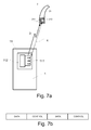
- FIG. 7a shows an embodiment of a system according to the invention.
- the master device 1 comprises transmitter 11 comprising drive circuit 112 and Tx-inductive coil 111.
- the slave device 2 (here having the form of a behind the ear part of a hearing instrument) comprises a receiver 21 comprising Rx-inductive coil 211 and receive circuitry 212.
- the transmitter 11 and receiver 21 are adapted so that an excitation of Tx-coil 111 with an upstream signal 3 results in a magnetic coupling with Rx-coil 211, when they are located within a predefined distance of each other (indicated by dashed arrow 4, referring to the linear path distance between the Tx- and Rx-coils) and a corresponding reception of the signal in receiver 21.
- the transmitter 11 is adapted to wirelessly transmit an upstream signal 3, schematically exemplified in FIG. 7b to comprise control packets embedded in a payload signal (here a realtime, continuous audio signal) and the receiver is adapted to receive said signal.
- a payload signal here a realtime, continuous audio signal
- the actual merging of the payload packets with the status packets may be performed in the transmitter or in another component of the master device 1 (e.g. in a processor).
- the actual separation of the received signal in payload (e.g. streaming audio) and control packets, respectively, can be performed in the receiver or elsewhere in the slave device, e.g. in a processor.
Landscapes
- Engineering & Computer Science (AREA)
- Computer Networks & Wireless Communication (AREA)
- Signal Processing (AREA)
- Health & Medical Sciences (AREA)
- General Health & Medical Sciences (AREA)
- Neurosurgery (AREA)
- Otolaryngology (AREA)
- Physics & Mathematics (AREA)
- Acoustics & Sound (AREA)
- Mobile Radio Communication Systems (AREA)
- Telephone Function (AREA)
Abstract
Description
- The invention deals with short range, uni-directional wireless communication. The invention relates specifically to a system comprising a master device and a slave device, the master device comprising a transmitter including a Tx-inductive coil, the slave device comprising a receiver including an Rx-inductive coil.
- The invention furthermore relates to a method of establishing a uni-directional wireless link for forwarding an upstream signal and at least one control signal from a master to a slave device.
- The invention furthermore relates to use of a system according to the invention.
- The invention may e.g. be useful in applications involving wireless communication between devices at least one of which is a low-power (e.g. battery driven) device, e.g. a portable device, e.g. a listening device, such as a hearing instrument.
- In applications involving wireless transmission of data between first and second electronic devices, one or more of the following issues can be important:
- There is limited available bandwidth and the need for upstream data streaming from the first to the second device prevents the use of bandwidth for down stream data.
- The second devices have transmitters, which are low powered in comparison with the first devices, providing asymmetrical transmission range. Thus the transmission range from the first to the second devices is longer than the range from the second to the first devices.
- Power is an issue on the second device, requiring the transmitter of that device to be kept off whenever possible.
- The first device is a transmit-only device, which cannot receive.
- The second device is a receive-only device, which cannot transmit.
- Such properties are e.g. important for wireless applications targeted towards listening devices, such as hearing aids, as they are physically very limited in size. The size causes a range of problems when applying wireless technologies to e.g. hearing aids, where the most significant are:
- Limited power budget, for both transmission and reception
- Relatively small antennas (low Rx-sensitivity and Tx-efficiency)
-
WO 2007/046748 discloses a system for assisting a hearing impaired user, the system comprising a transmitter and receiver adapted to convey data representing audio to a user. The audio data may originate from a microphone, a speaker, a TV, a telephone, etc. The transmitter device may be configured to transmit control signals while continuing to transmit audio data (e.g. using another radio channel or by time multiplexing with the audio data). -
WO 2007/052189 discloses a hearing aid system aiming at allowing a user himself to adapt the gain characteristics, etc. of a hearing aid device to his personal needs. In a specific control mode, the hearing aid device is configured to, during a control signal detection period, be programmed by control signals embedded in audio signals - The invention relates to a one-directional (in the following termed 'uni-directional') wireless link from a master (M) device to one or several slave (S) devices. The respective 'devices' are in the following occasionally termed 'nodes' when used in connection with network issues. Each set of (matching) master node and slave node(s) form a wireless network called a "Body Area Network" (BAN).
- The problems of the prior art translate to a range of issues:
- Due to a limited power budget, the slave device(s) (e.g. hearing instrument(s)) cannot be allowed to transmit continuously.
- Due to the small antenna size, a comparatively high power is required to obtain a stable back-link (from slave to master device). Even if higher power consumption could be allowed, achieving a symmetrical range would still be difficult.
- When employing a half-duplex link, the bandwidth used for a back-link reduces the possible uplink data rate (from master to slave device).
- An object of the present invention is to solve one or more problems of the prior art.
- Objects of the invention are achieved by the invention described in the accompanying claims and as described in the following.
- An object of the invention is achieved by a system comprising a master device and at least one slave device, the master device comprising a transmitter including a Tx-inductive coil, and the at least one slave device comprising a receiver including an Rx-inductive coil. Advantageously, the master and slave devices are adapted to establish a uni-directional wireless link for forwarding an upstream signal from the master to the slave device via the inductive coupling between the Tx- and Rx-induction coils when the master and slave devices are located within a certain distance from each other, wherein the master device is adapted to provide that the upstream signal comprises a payload signal and at least one control signal, the at least one control signal is/are are embedded in the payload signal and repeated according to a predefined scheme, and wherein the at least one control signal represents an intended current setting of an operational parameter of the slave device.
- An advantage of the invention is that it provides a scheme for wirelessly controlling and changing the settings of a slave device from a master device using a uni-directional link from master to slave device. A further advantage is that the power consumption in the slave device for communications purposes can be minimized. A further advantage is that the control of the slave device can be performed, while maintaining an uninterrupted stream of data, e.g. audio data.
- Embodiments of the invention provide one or more of the following features:
- Continuous synchronization between slave node(s) within a range of the master node without requiring the slave node(s) to transmit.
- Secure transfer of data from master node to slave node(s) to maintain privacy.
- Allows for multiple BANs within a limited physical space.
- These features are designed to support a fully operational system for which the need for a back-link is eliminated.
- The term 'a payload signal' is in the present context taken to mean a signal containing information of a specific kind or utility (a 'desired signal'), e.g. 'audio' or 'video' (the term is used to separate its contents from control signals and the like). In a particular embodiment, a payload signal is a continuous signal. In a particular embodiment, a payload signal is a realtime signal, such as an audio signal that is continuously produced by a source.
- The term 'embedded in' is in the present context intended to have its ordinary meaning, e.g. 'included in' or 'mixed with' or 'surrounded by' or 'enclosed in'.
- A control signal for the setting of an operational parameter is preferably transmitted as a parameter representative of an absolute value (as opposed to a relative value in the form of an incremental change compared to a previous value) and the master and slave devices are correspondingly adapted. Thereby the system becomes more robust to transmission errors or non-availability of the link, and there is no need for keeping track of previous values, making the system simpler.
- In a particular embodiment, the system is adapted to provide that the at least one control signal is/are assembled in a status packet of the transmitted signal. In an embodiment, the reception of the status packet in the receiver initiates an update of the setting of the operational parameter(s) of the slave device with the value(s) contained in the received status packet.
- The repeated (e.g. periodic) transmission of absolute (control) parameter values enables the slave device to synchronize to the master devices at once, whenever a status packet is received and interpreted in the slave device. This provides a significant redundancy to the system, because the current control signals contained in the current status packet can be directly correlated to the current values of the state variables of the remote (slave) device, without knowledge of the prior values of the state variables.
- The independence of the transmitted (current) values of the prior values of the control signals is particularly advantageous for systems depending on unidirectional links, where no acknowledgement of receipt (back to the master device) is available from the slave device, and thus no information on whether the control signals have been received and interpreted correctly by the slave device is available in the master device.
- In a particular embodiment, the slave device forms part of a body-worn electronic device. In a particular embodiment, the slave device is a battery driven device, such as a listening device, e.g. a hearing instrument. In the present context 'battery driven' is intended to include any type of local source of energy adapted to provide power to movable, handheld or body worn electronic devices, such local source of energy including rechargeable or non-rechargeable batteries, fuel cells, etc.
- The term 'a system' (e.g. a listening system) includes an audio system comprising a number of devices (such as two or more, typically two or three devices, at least one of which is adapted for being worn in full or partially in or at a left and/or right ear of a wearer). The term a listening device comprises a hearing instrument, a headset, a head phone, an ear-plug, etc. The term a 'listening system' may include a pair of hearing instruments of a binaural fitting or a pair of head phones or a pair of active ear-plugs and combinations thereof (e.g. headphones or headsets or ear-plugs that also have a hearing instrument function or one head phone and one hearing instrument, etc.).
- The term a 'hearing instrument' is in the present context taken to mean a hearing aid comprising a signal processor whose gain profile (gain vs. frequency) can be (or has been) adapted to a specific wearer's needs to compensate for a hearing loss and/or to protect a wearer against outside excessive sound levels.
- In a particular embodiment, the master device comprises an audio selection device for selecting an audio signal among a multitude of audio signals and forwarding the selected signal to the slave device. In a particular embodiment, the master device comprises a remote control device for setting particular parameters of the slave device.
- The use of inductive communication between the master and slave devices ensures a relatively limited range of communication (at the available power levels) thereby effectively providing localized BANs and enabling a relatively large spatial 'density' of BANs using the same frequency spectrum. The magnetic field coupling between two adjacent Tx- and Rx-inductive coils falls off as r3, where r is the distance between the coils. The transmission range can thus be controlled by controlling the Tx-power emitted by the master device. Corresponding values of settable Tx-power and transmission ranges having a predefined acceptable transmission quality (e.g. as indicated by a predefined average bit error rate), e.g. with predefined orientations of the Tx- and Rx-coils relative to each other, can advantageously be initially determined. In a particular embodiment, the system is adapted to function within a predefined transmission range. In an embodiment the orientation of the Tx-coil or coils of the master device and the orientation of the Rx-coil or coils of the master device relative to each other is optimized to provide maximum transmission range, when the master and slave devices are used in their normal operative environment and position (the master device e.g. being worn in a loop around the neck or carried in a pocket or fixed to a belt, etc. of a person, and the slave device e.g. being worn at or in an ear of the same person).
- In a particular embodiment, the system is adapted to optimize the wireless link to function properly when the distance between the locations of the master and slave devices is smaller than a certain maximum BAN-distance, e.g. smaller than 2 m, such as smaller than 1.5 m, such as smaller than 1 m, such as smaller than 0.6 m, such as smaller than 0.5 m. In a particular embodiment, the system is adapted to optimize the wireless link to function properly when the distance between the locations of the master and slave devices is in the range from 0.1 m to 2 m, such as 0.2 m to 1.5 m. The term 'function properly' can e.g. be based on achieving a transmission with a maximum predefined average bit error rate at a predefined transmission bit rate (e.g. determined by measurement prior to the intended use of the system).
- In an embodiment, the master device comprises more than one Tx-inductive coil to improve the transmitted inductive signal. In an embodiment, the slave device comprises more than one Rx-inductive coil to improve the conditions for reception of a transmitted inductive signal from a corresponding master device. In an embodiment, the mutual orientation of the more than one Tx-coils is optimized to provide a particular form and homogeneity of the resulting magnetic field (and thus the BAN). In an embodiment, the mutual orientation of the more than one Rx-coils is optimized to the particular form and homogeneity of the resulting magnetic field from the corresponding master device, when the slave device is located at its normal operative position in the BAN relative to the master device.
- In an embodiment, the inductive coupling between the master device and the slave device is optimized to a predefined frequency range, e.g. by adapting the number of turns, the values of a capacitor and/or a resistor of a resonance circuit formed by the coil, the capacitor and/or the resistor to provide a specific preferred frequency range for the inductive communication. Such optimization is preferably performed for each of the coil circuits of the involved master and slave devices. The communication between the master device and the slave device may in principle be in any frequency range, e.g. in the RF-range. In an embodiment, the preferred range is in the MHz-range (e.g. in the range between 1 MHz and 30 MHz or between 10 MHz and 100 MHz).
- If interference between several master devices possibly issuing 'conflicting' signals and one or more slave devices is not possible (or is acceptable), no particular matching of a master device to one or more particular slave devices is necessary. A master device is, however, typically adapted for being matched (paired) with at least one specific slave device (which, on the other hand, is adapted to be matched with the master device in question). The matching can be governed by any appropriate means.
- In a particular embodiment, the linking procedure between master and slave is based on the identification of a predefined security key in the slave device corresponding to a predefined security key of the master device, e.g. in the form of a number of encrypted or non-encrypted bits. The complexity of the security key (including its length) can advantageously be adapted to the level of security of the application in question. A master and a slave device are said to be paired or matched, for example if they have been provided with corresponding security keys.
- In a particular embodiment, the master device is adapted to provide that the transmitted payload signal comprises packets of data, e.g. audio data (i.e. data representing an audio signal, e.g. music). In an embodiment, the signal transmitted from a master device to a slave device in addition to a control signal representing an intended current setting of an operational parameter of the slave device comprises a link security key for allowing a particular slave device to receive the payload of a transmitted signal from the master device in question.
- In a particular embodiment, the system is adapted to provide that the transmitted payload signal comprises packets of data and packets of status signals.
- In a particular embodiment, the system is adapted to provide that the control signal(s) form(s) part of the packets of status signals. In a particular embodiment, the system is adapted to provide that the security key forms part of the packets of status signals.
- In a particular embodiment, the system is adapted to provide that the reception of the status packet initiates an update of the setting of the operational parameter(s) of the slave device with the value(s) contained in the received status packet or based thereon.
- In an embodiment, a status packet is attached to every payload data packet, or to every second data packet or to every 5th or 10th data packet. In an embodiment, a status packet is attached to every Nth data packet, where N is larger than 3, such as larger than 7, such as larger than 20, such as larger than 50. In an embodiment, the frequency of occurrence of the status packet is determined (e.g. dynamically) according to the available bandwidth. The 'available bandwidth' is the residual bandwidth considering the link bandwidth at hand (determined by the transmission rate) and the bandwidth occupied by the 'payload signal' (e.g. a realtime audio signal). The payload-bandwidth is typically determined by a chosen transmission standard.
- In an embodiment, the frequency of occurrence of status packets is relatively higher during relatively high bandwidth utilization of the payload signal, while the frequency of occurrence of status packets is relatively lower during relatively low bandwidth utilization of the payload signal. Fore example, in applications with only low bandwidth utilization, for instance during streaming of audio in low quality from e.g. telephones, the status packets can be transmitted more frequently, to utilize the excess bandwidth. The higher frequency of occurrence of status packets enables the slave device(s) (e.g. hearing instrument(s)) to be synchronized faster. When a higher bandwidth is required, e.g. during transmission of audio at a higher quality, the frequency of the status packets can be decreased in order to provide more bandwidth for the audio transmission.
- In an embodiment, the data packets comprise audio data. In an embodiment the data packets together represent a continuous, realtime audio signal (continuous in the sense that it is continuously generated by a source, e.g. with a duration of more than 10 seconds, such as more than one minute and realtime in the sense that it is transmitted with substantially the same rate that it is generated, or in the sense that it is transmitted as data arrives from a source, in other words without larger parts (e.g. of a duration of more than 100 ms or 1 s or 10 s or more) of the transmitted payload signal being specifically stored in a storage medium other than a temporary buffer).
- In an embodiment, a link security key for matching a master to a slave device is attached to each data packet.
- In a particular embodiment, the at least one control signal and/or link security key and/or status packet is periodically repeated in the payload signal, e.g. at least every 1 s, such as at least every 1 ms, such as with a repetition time in the range from 100 ms to 500 ms, e.g. around 200 ms.
- In a particular embodiment, the length of a status packet is optimized with regard to minimizing latency. In an embodiment, a status packet is broken into several packets that are distributed in the payload (e.g. evenly distributed) to minimize latency. In an embodiment, the system is adapted to provide that the latency (delay) of the audio signal received by the receiver compared to the original audio signal (e.g. as fed to the transmitter) is smaller than 30 ms, such as smaller than 20 ms, such as smaller than 15 ms, such as smaller than 10 ms.
- The length of a status packet (as given in time or number of bits (at a given bit rate)), and thus the time it takes to transmit it constitutes the minimum buffer length required in the receiver in order to provide an uninterrupted real time data (audio) stream. As the length of the status packets are shortened, the buffer length required on the receiver approaches 0.
- A status packet typically consists of a header and an information-content (e.g. a control signal, a security key, etc.). The shortening of the status packet can only be done effectively until a certain threshold length, where a further shortening leads to an overall higher bandwidth requirement, because more instances of the status packet header will be required to transmit the same information-content. In general, though, lower status packet length and lower status packet transmission frequency (and thus lower synchronization speed) can be traded for more bandwidth to the payload data stream. Similarly, lower latency and/or higher synchronization speed can be achieved, if accepting less bandwidth for the real time (payload) data stream. The adaptation of the frequency of occurrence and/or the length of status packets can be implemented in software.
- In a particular embodiment, a control signal is used for controlling the volume setting of the listening device.
- In a particular embodiment, the at least one control signal comprises control signals for the setting of one or more parameters of the slave device selected from the group of parameters comprising receiver volume, program selection (e.g. specifying a program optimized to a particular acoustical environment or to a particular quality of the received signal, setting the microphone on or off, etc.), sound effects (e.g. a call tone indicating a telephone call or other acoustic signals with predefined meaning), type of audio signal transmitted (e.g. telephone signal, music, stereo, etc., possibly represented by a bandwidth specifying signal).
- In a particular embodiment, the system is adapted to provide that the security key is checked every time a status packet is received.
- In a particular embodiment, the system is adapted to provide a data transmission rate of the uni-directional link in the range from 50 kbit/s to 1 Mbit/s, such as in the range from 100 kbit/s to 500 kbit/s.
- It is intended that the features of the system described above, in the detailed description describing modes for carrying out the invention and in the claims can be combined with the method as described below. The method and its embodiments have the same advantages as the corresponding system described above.
- In an aspect, A method of establishing an uni-directional wireless link for forwarding an upstream signal from a master to a slave device is furthermore provided by the present invention. The method comprises
- a) providing a master device comprising a transmitter including a Tx-inductive coil;
- b) providing a slave device comprising a receiver including an Rx-inductive coil;
- c) providing that the master and slave devices are located within a certain distance from each other to provide an appropriate inductive coupling between the Tx- and Rx-induction coils enabling inductive communication from transmitter to receiver;
- d) providing that the upstream signal comprises a payload signal and at least one control signal;
- e) providing that at least one control signal is/are are embedded in the payload signal and repeated according to a predefined scheme; and
- f) providing that the at least one control signal represents an intended current setting of an operational parameter of the slave device. This has the advantage that power consumption in the slave device for communications purposes can be minimized.
- In a particular embodiment, the method comprises providing the master device with a security key and providing the at least one slave device that is/are intended to receive a transmitted signal from the master device with the a corresponding predefined key.
- In a particular embodiment, the method comprises establishing a linking mode wherein the security key received in the at least one slave device is compared to the predefined key of the device in question.
- In a particular embodiment, the method comprises providing that the at least one control signal is/are assembled in a status packet of the transmitted signal and that the reception of the status packet initiates an update of the setting of the operational parameter(s) of the slave device with the value(s) contained in the received status packet.
- In a particular embodiment, the method comprises providing that the frequency of occurrence of the status packet is determined, such as dynamically determined, according to the available bandwidth.
- In a particular embodiment, the method comprises providing that the payload signal represents a continuous, realtime audio signal.
- In a particular embodiment, the method comprises providing that the length and/or frequency of occurrence in the payload signal of a status packet is optimized with regard to minimizing latency.
- In a particular embodiment, the method comprises providing that the frequency of occurrence of status packets is relatively higher during relatively high bandwidth utilization of the payload signal, while the frequency of occurrence of status packets is relatively lower during relatively low bandwidth utilization of the payload signal.
- In a particular embodiment, the method comprises providing that the control signal representing an intended current setting of an operational parameter of the slave device is transmitted as a parameter representative of an absolute value.
- Use of a system according to anyone of claims 1-14 is moreover provided by the present invention, e.g. in a listening system, e.g. a hearing aid system. In a particular embodiment, the slave device of the used system form part of a listening device, e.g. a hearing instrument. In a particular embodiment, the master device of the used system form part of a communications device, e.g. an audio selection device, adapted for establishing a wireless link to another device in the system, e.g. a hearing instrument.
- Further objects of the invention are achieved by the embodiments defined in the dependent claims and in the detailed description of the invention.
- As used herein, the singular forms "a," "an," and "the" are intended to include the plural forms as well (i.e. to have the meaning "at least one"), unless expressly stated otherwise. It will be further understood that the terms "includes," "comprises," "including," and/or "comprising," when used in this specification, specify the presence of stated features, integers, steps, operations, elements, and/or components, but do not preclude the presence or addition of one or more other features, integers, steps, operations, elements, components, and/or groups thereof. It will be understood that when an element is referred to as being "connected" or "coupled" to another element, it can be directly connected or coupled to the other element or intervening elements maybe present, unless expressly stated otherwise. Furthermore, "connected" or "coupled" as used herein may include wirelessly connected or coupled. As used herein, the term "and/or" includes any and all combinations of one or more of the associated listed items. The steps of any method disclosed herein do not have to be performed in the exact order disclosed, unless expressly stated otherwise.
- The invention will be explained more fully below in connection with a preferred embodiment and with reference to the drawings in which:
-
FIG. 1 shows the asynchronous range between master and slave node, -
FIG. 2 shows multiple BANs allowed within a confined space due to limited range, -
FIG. 3 shows non-linked slave device within another BAN, -
FIG. 4 illustrates the difference between absolute and relative control, -
FIG. 5 shows an example of the embedding of status data, -
FIG. 6 shows an example of an upstream signal comprising data and status packets (a) and an example of the contents of a data packet (b), and -
FIG. 7a shows a system according to an embodiment of the invention and -
FIG. 7b shows a schematic example of the composition of a transmitted upstream signal. - The figures are schematic and simplified for clarity, and they just show details which are essential to the understanding of the invention, while other details are left out. Throughout, the same reference numerals are used for identical or corresponding parts.
- Further scope of applicability of the present invention will become apparent from the detailed description given hereinafter. However, it should be understood that the detailed description and specific examples, while indicating preferred embodiments of the invention, are given by way of illustration only, since various changes and modifications within the spirit and scope of the invention will become apparent to those skilled in the art from this detailed description.
-
Fig. 1 shows the asynchronous range between master and slave node. In a battery driven communications device, such as a hearing instrument, where space is at a minimum, power consumption of any particular function, here wireless communication, is an important issue. The small capacity of a battery (or other energy source) of a hearing instrument results in a relatively low spatial range of transmission of a wireless link as illustrated by the relatively shorter arrow from the Slave (e.g. a hearing instrument) to the Master (e.g. an audio selection device). An example of a system comprising a hearing instrument and an audio selection device is e.g. described inEP 1 460 769 A1WO 2007/046748 . An example of a system comprising a hearing instrument and a remote control device with a uni-directional link based on inductive communication is e.g. described inUS 6,816,600 . Inductive communication (i.e. communication based on electromagnetic induction as opposed to electromagnetic radiation) between a hearing instrument and a gateway device in accordance with a standard or proprietary protocol is e.g. described inEP 1 480 492 A2 - The invention relies on an inductive link which provides a relatively homogenous field within a limited area. Outside this area, the field strength drops off rapidly, thus limiting the functional range to this confined area.
- This allows, as illustrated in
FIG. 2 , for multiple BANs operating within a limited space without interfering with each other, allowing for reuse of the same frequencies throughout the area as well as effectively preventing other parties from picking up a transmission. Various combinations of master and slave devices located within the same BAN (and where it is assumed that master and slave(s) are mutually matched) are indicated inFIG. 2 . Combinations include a) a master device with a uni-directional (one-way) wireless link to one slave device, b), c) a master device with uni-directional wireless links to two slave devices, d) a master device with uni-directional wireless links to three slave devices, e) a master device (e.g. a remote control) with a uni-directional wireless link to one slave device, where the one slave device has a bi-directional (two-way) wireless link to another slave device). Situation e) can e.g. describe an audio selection (master) device wirelessly communicating with a first listening (slave) device of a binaural system (e.g. a binaural hearing aid system) wherein the first listening (slave) device can communicate wirelessly with a second listening device via a bi-directional link (e.g. a short range (e.g. 20-30 cm), relatively low bandwidth communication link, e.g. based on inductively coupled coils in each listening device or based on radiated electromagnetic fields). Alternatively or additionally situation e) can describe a remote control (master device) wirelessly transmitting settings to a first listening (slave) device of a binaural system wherein the first listening e.g. forwards the settings from the remote control to the other (slave) device and/or synchronizing status signals can be exchanged between the (slave) devices of the binaural system. - In an embodiment, a data transmission rate of the uni-directional link from the master node to the slave node is in the range from 50 kbit/s to 1 Mbit/s, such as in the range from 100 kbit/s to 500 kbit/s, such as e.g. around 200 kbit/s.
- The link security is based on two tiers. First of all a perpetrator has to be within range of the BAN in order to pick up the signal and in order to listen in a security key has to be known. Given the properties of the inductive link, this means that any perpetrator would need to be within less than 2 meters in order to be able to receive the streaming from the master device. Embodiments may be implemented with a special view to reducing the range of the inductive link to less than 1.5 m or less than 1 m (which additionally conserves energy in the master device).
- To provide additional security, a security key is required in order to receive the streaming.
- The linking procedure is the exchange of the security key. The key can either be exchanged manually or transmitted wirelessly from master node to slave node(s), after putting the slave node(s) into a special "linking mode". After completing the linking process, slave and master devices are able to communicate.
- In order for the slave node(s) to receive the signal it/they need to know the security key. A security key can comprise a smaller or larger amount of bits, depending on the degree of security needed. The security key can be randomly generated or e.g. a unique identification code for the master device. The system is adapted to provide that the key is known by both the master and the slave node(s) and used to maintain privacy by securing the transmission. The security key can e.g. be coded into matching master and slave devices in separate product matching procedure, when the devices are sold or packaged or customized to a particular user. In case of a slave device being a hearing instrument, the pairing to a master device (e.g. an audio selection device or a remote control for the hearing instrument) can conveniently take place in connection with the user customization of the hearing instrument, where settings adapted to the needs of a particular user are fed to the hearing instrument, typically using a fitting software running on a programming unit (e.g. a PC) and transferred to the hearing instrument via a wired or wireless interface.
- In order for any perpetrator to eavesdrop on the connection their slave node(s) need to have the key used by the master node. If a relevant security code is not known by a slave device receiving an upstream signal from a master device, the received signal is discarded.
- The link is secured by the master node adding the security key to each data packet transmitted. Whenever a slave node receives a data packet, it checks the security key to see whether the packet is sent using an allowed key. If the key is not recognized, the data packet is discarded, where the packet is passed on if the key is recognized.
- In situations where no or little excess bandwidth is available, say during audio streaming, a different scheme is used. During continuous data streaming of non-critical data, the key is not added to each packet. Instead it is transmitted at longer interval, by embedding a status packet into the data stream. Every time a status packet is received, the security key is examined and if the key is known, the stream processing is started, or allowed to continue. If the key does not match any known keys, the stream processing is stopped in the slave device in question as illustrated in
FIG. 3. Fig. 3 shows non-linked slave device within another BAN, illustrating a situation where one non-matching (as indicated by ∅-symbol 34) slave device 33 (e.g. a hearing aid) is located within the range of aBAN 35 as defined by the master 31 (e.g. an audio selection device). Two matching slave devices 33 (e.g. a pair of hearing aids) are further present in the BAN. - The system is designed to transfer control data from the master node to the slave node(s).
- The master node provides continuous synchronization between the attached slave nodes by periodically transmitting the state variables which are changeable. Whenever a slave node enters the BAN, it will synchronize to the state of the BAN master node upon receiving a status packet.
- If a slave node is out of range, and re-enters the BAN, it will automatically resynchronize to the same state variables as the other slaves in the BAN upon receiving a status packet.
- In order to provide robust synchronization between master and slave node(s), all state variables should be transferred as absolutes, rather than as relatives. This means that if for instance a state variable is changed from 5 to 7, it should be transmitted continuously as 7 rather than a single time as a 2 increment.
-
Fig. 4 illustrates the difference between absolute and relative control, where the top line shows a status change with a slave node within range. In this case operation will be the same for both relative an absolute control. The second line shows what happens if the link is temporarily down while a relative change is sent. Even though the message is sent, nothing happens, as the change is not received, and it is never retransmitted. The bottom line shows what happens in the same situation, using absolute control. In this case the state information is transmitted periodically, and as soon as the link is reconnected to the slave device, it will start receiving status data again, and resynchronise to the master device. - In situations where the master node is transmitting a continuous stream of data, the synchronization data can be embedded periodically into the data stream in order to provide synchronization even though data is streamed. In an embodiment, the status packet is periodically repeated as illustrated in
FIG. 5 , e.g. every 200 ms.Fig. 5 shows an example of the repetitive (here periodic) embedding ofstatus data 51 in a continuous audio stream 52 (payload) signal. - The embedding of status data causes a slight latency as stream data should be buffered in order to have a continuous stream even though it is interrupted by status information. In order to keep the latency as low as possible, the status data should be broken up into many short chunks rather than fewer larger. Preferably, the short chunks are distributed evenly in the payload signal.
-
FIG. 6a shows an example of an upstream signal transmitted by a master device to a slave device and comprising a payload signal and control signals. The payload signal comprises data packets (DATA) and status packets (STATUS). The status packets comprise control signals for setting operational parameters of a matching slave device.FIG. 6b shows in more detail an example of the contents of a status packet ofFIG. 6a . The status packet comprises the control signals SEL, VOL, PROG and SOUND representative of the setting of corresponding parameters of the slave device. The status packet further comprises a security key (SEC. KEY) to be matched by a slave device in order for the slave device to accept the transmission. The select control signal SEL specifies the type of audio signal transmitted (e.g. telephone signal, music, stereo, etc., possibly represented by a bandwidth specifying signal). The volume control signal VOL is the intended setting of receiver volume of the slave device in a format representative of the intended level of volume in absolute terms. The program control signal PROG can e.g. initiate the selection of a program optimized to a particular acoustical environment or to a particular quality of the received signal, or initiate the setting the microphone to on or off, etc. The sound control signal SOUND is a control signal for sound effects to be indicated to a user via a receiver of the slave device, e.g. a call tone indicating a telephone call or other acoustic signals with predefined meaning). -
FIG. 7a shows an embodiment of a system according to the invention. Themaster device 1 comprisestransmitter 11 comprisingdrive circuit 112 and Tx-inductive coil 111. The slave device 2 (here having the form of a behind the ear part of a hearing instrument) comprises areceiver 21 comprising Rx-inductive coil 211 and receivecircuitry 212. Thetransmitter 11 andreceiver 21 are adapted so that an excitation of Tx-coil 111 with anupstream signal 3 results in a magnetic coupling with Rx-coil 211, when they are located within a predefined distance of each other (indicated by dashedarrow 4, referring to the linear path distance between the Tx- and Rx-coils) and a corresponding reception of the signal inreceiver 21. - The
transmitter 11 is adapted to wirelessly transmit anupstream signal 3, schematically exemplified inFIG. 7b to comprise control packets embedded in a payload signal (here a realtime, continuous audio signal) and the receiver is adapted to receive said signal. The actual merging of the payload packets with the status packets may be performed in the transmitter or in another component of the master device 1 (e.g. in a processor). Similarly, the actual separation of the received signal in payload (e.g. streaming audio) and control packets, respectively, can be performed in the receiver or elsewhere in the slave device, e.g. in a processor. - The invention is defined by the features of the independent claim(s). Preferred embodiments are defined in the dependent claims. Any reference numerals in the claims are intended to be non-limiting for their scope.
- Some preferred embodiments have been shown in the foregoing, but it should be stressed that the invention is not limited to these, but may be embodied in other ways within the subject-matter defined in the following claims.
-
-
WO 2007/046748 (CRAJ DEVELOPMENT) 26-04-2007 -
WO 2007/052189 (PHILIPS) 10-05-2007 -
EP 1 460 769 A1 -
US 6,816,600 (PHONAK) 09-11-2004 -
EP 1 480 492 A2
Claims (27)
- A system comprising a master device and at least one slave device,• the master device comprising a transmitter including a Tx-inductive coil,• the at least one slave device comprising a receiver including an Rx-inductive coil,wherein
the master and slave devices are adapted to establish a uni-directional wireless link for forwarding an upstream signal from the master to the slave device via the inductive coupling between the Tx- and Rx-induction coils when the master and slave devices are located within a certain distance from each other, wherein the master device is adapted to provide that the upstream signal comprises a payload signal and at least one control signal, the at least one control signal is/are are embedded in the payload signal and repeated according to a predefined scheme, and wherein the at least one control signal represents an intended current setting of an operational parameter of the slave device. - A system according to claim 1, wherein the master and slave devices are adapted to provide that the control signal representing an intended current setting of an operational parameter is transmitted as parameter representative of an absolute value.
- A system according to claim 1 or 2, wherein the slave device is a battery driven device, such as a listening device, e.g. a hearing instrument, a headset, a head phone, or an active earplug.
- A system according to any one of claims 1-3, wherein the master device comprises a remote control of the slave device and/or an audio selection device for selecting an audio signal among a multitude of audio signals and forwarding the selected signal to the slave device.
- A system according to any one of claims 1-4, adapted to provide that the transmission range is controlled by controlling the Tx-power emitted by the master device, e.g. by providing corresponding values of settable Tx-power and transmission ranges having a predefined acceptable transmission quality.
- A system according to any one of claims 1-5 adapted to provide that the linking procedure between master and slave is based on the identification of a predefined security key in the slave device.
- A system according to any one of claims 1-6 adapted to provide that the at least one control signal is periodically repeated in the payload signal, e.g. at least every 1 s, such as at least every 1 ms, such as in the range from 100 ms to 500 ms.
- A system according to any one of claims 1-7 adapted to provide that a control signal is used for controlling the volume setting of the listening device.
- A system according to any one of claims 1-9 adapted to optimize the wireless link to function properly when the distance between the locations of the master and slave devices is smaller than a certain maximum BAN-distance, e.g. smaller than 1 m such as smaller than 0.6 m, such as smaller than 0.5 m.
- A system according to any one of claims 1-9 adapted to provide that the at least one control signal comprises control signals for the setting of one or more parameters of the slave device selected from the group of parameters comprising receiver volume, program selection, sound effects, type of audio signal transmitted.
- A system according to any one of claims 1-10 adapted to provide that the at least one control signal is/are assembled in a status packet of the transmitted signal and that the reception of the status packet initiates an update of the setting of the operational parameter(s) of the slave device with the value(s) contained in the received status packet.
- A system according to claim 11, when dependent on any one of claims 6-10, adapted to provide that the security key is checked every time a status packet is received in the slave device.
- A system according to claim 11 or 12 adapted to provide that the frequency of occurrence of the status packet is determined, such as dynamically determined, according to the available bandwidth.
- A system according to any one of claims 1-13 adapted to provide a data transmission rate of the uni-directional link in the range from 50 kbit/s to 1 Mbit/s, such as in the range from 100 kbit/s to 500 kbit/s.
- A method of establishing an uni-directional wireless link for forwarding an upstream signal from a master to a slave device, comprisinga) providing a master device comprising a transmitter including a Tx-inductive coil;b) providing a slave device comprising a receiver including an Rx-inductive coil;c) providing that the master and slave devices are located within a certain distance from each other to provide an appropriate inductive coupling between the Tx- and Rx-induction coils enabling inductive communication from transmitter to receiver;d) providing that the upstream signal comprises a payload signal and at least one control signal;e) providing that at least one control signal is/are are embedded in the payload signal and repeated according to a predefined scheme; andf) providing that the at least one control signal represents an intended current setting of an operational parameter of the slave device.
- A method according to claim 15 comprising providing the master device with a security key and providing the at least one slave device that is/are intended to receive a transmitted signal from the master device with a corresponding predefined key.
- A method according to claim 16 comprising a linking mode wherein the security key received in the at least one slave device is compared to the predefined key of the device in question.
- A method according to any one of claims 15-17 providing that the at least one control signal is/are assembled in a status packet of the transmitted signal and that the reception of the status packet initiates an update of the setting of the operational parameter(s) of the slave device with the value(s) contained in the received status packet.
- A method according to claim 18 providing that the frequency of occurrence of the status packet is determined, such as dynamically determined, according to the available bandwidth.
- A method according to claim 19 providing that the frequency of occurrence of status packets is relatively higher during relatively high bandwidth utilization of the payload signal, while the frequency of occurrence of status packets is relatively lower during relatively low bandwidth utilization of the payload signal.
- A method according to any one of claims 15-20 wherein the payload signal represents a continuous, realtime audio signal.
- A method according to any one of claims 18-21 wherein the length and/or frequency of occurrence in the payload signal of a status packet is optimized with regard to minimizing latency.
- A method according to any one of claims 15-22 wherein the control signal representing an intended current setting of an operational parameter of the slave device is transmitted as a parameter representative of an absolute value.
- Use of a system according to anyone of claims 1-14.
- Use according to claim 24 in a listening system, e.g. a hearing aid system.
- Use according to claim 25 wherein the slave device form part of a listening device, e.g. a hearing instrument.
- Use according to claim 25 or 26 wherein the master device form part of a communications device, e.g. an audio selection device, adapted for establishing a wireless link to another device in the system, e.g. a hearing instrument.
Priority Applications (10)
| Application Number | Priority Date | Filing Date | Title |
|---|---|---|---|
| EP08103848.1A EP2117180B1 (en) | 2008-05-07 | 2008-05-07 | A short range, uni-directional wireless link |
| DK08103848.1T DK2117180T3 (en) | 2008-05-07 | 2008-05-07 | A short-range wireless one-way connection |
| CN200980116448.7A CN102017779B (en) | 2008-05-07 | 2009-05-06 | short-range one-way wireless link |
| PCT/EP2009/055475 WO2009135872A1 (en) | 2008-05-07 | 2009-05-06 | A short range, uni-directional wireless link |
| US12/991,183 US8831508B2 (en) | 2008-05-07 | 2009-05-06 | Short range, uni-directional wireless link |
| EP13169351.7A EP2637470B1 (en) | 2008-05-07 | 2009-05-06 | A short range, uni-directional wireless link |
| DK09742090.5T DK2283692T3 (en) | 2008-05-07 | 2009-05-06 | A WIRELESS SHORT-WAY ROAD CONNECTION |
| EP09742090.5A EP2283692B1 (en) | 2008-05-07 | 2009-05-06 | A short range, uni-directional wireless link |
| DK13169351.7T DK2637470T3 (en) | 2008-05-07 | 2009-05-06 | A short-range, unidirectional wireless connection |
| AU2009245803A AU2009245803B2 (en) | 2008-05-07 | 2009-05-06 | A short range, uni-directional wireless link |
Applications Claiming Priority (1)
| Application Number | Priority Date | Filing Date | Title |
|---|---|---|---|
| EP08103848.1A EP2117180B1 (en) | 2008-05-07 | 2008-05-07 | A short range, uni-directional wireless link |
Publications (2)
| Publication Number | Publication Date |
|---|---|
| EP2117180A1 true EP2117180A1 (en) | 2009-11-11 |
| EP2117180B1 EP2117180B1 (en) | 2013-10-23 |
Family
ID=39941808
Family Applications (3)
| Application Number | Title | Priority Date | Filing Date |
|---|---|---|---|
| EP08103848.1A Not-in-force EP2117180B1 (en) | 2008-05-07 | 2008-05-07 | A short range, uni-directional wireless link |
| EP13169351.7A Not-in-force EP2637470B1 (en) | 2008-05-07 | 2009-05-06 | A short range, uni-directional wireless link |
| EP09742090.5A Not-in-force EP2283692B1 (en) | 2008-05-07 | 2009-05-06 | A short range, uni-directional wireless link |
Family Applications After (2)
| Application Number | Title | Priority Date | Filing Date |
|---|---|---|---|
| EP13169351.7A Not-in-force EP2637470B1 (en) | 2008-05-07 | 2009-05-06 | A short range, uni-directional wireless link |
| EP09742090.5A Not-in-force EP2283692B1 (en) | 2008-05-07 | 2009-05-06 | A short range, uni-directional wireless link |
Country Status (6)
| Country | Link |
|---|---|
| US (1) | US8831508B2 (en) |
| EP (3) | EP2117180B1 (en) |
| CN (1) | CN102017779B (en) |
| AU (1) | AU2009245803B2 (en) |
| DK (3) | DK2117180T3 (en) |
| WO (1) | WO2009135872A1 (en) |
Cited By (1)
| Publication number | Priority date | Publication date | Assignee | Title |
|---|---|---|---|---|
| EP3351163A1 (en) * | 2017-01-20 | 2018-07-25 | Byteflies NV | Method for providing synchronization between a plurality of wireless body sensors and method for operating a synchronized network of wireless body sensors |
Families Citing this family (37)
| Publication number | Priority date | Publication date | Assignee | Title |
|---|---|---|---|---|
| EP2392085B1 (en) * | 2009-01-28 | 2021-06-23 | Samsung Electronics Co., Ltd. | Portable terminal and sound detector, which both communicate using body area network, and data controlling method therefor |
| EP2381700B1 (en) | 2010-04-20 | 2015-03-11 | Oticon A/S | Signal dereverberation using environment information |
| DK2503794T3 (en) | 2011-03-24 | 2017-01-30 | Oticon As | Audio processing device, system, application and method |
| US20120268414A1 (en) * | 2011-04-25 | 2012-10-25 | Motorola Mobility, Inc. | Method and apparatus for exchanging data with a user computer device |
| EP2519032A1 (en) | 2011-04-26 | 2012-10-31 | Oticon A/s | A system comprising a portable electronic device with a time function |
| EP2528356A1 (en) | 2011-05-25 | 2012-11-28 | Oticon A/s | Voice dependent compensation strategy |
| EP2533550B2 (en) | 2011-06-06 | 2021-06-23 | Oticon A/s | A hearing device for diminishing loudness of tinnitus. |
| EP2541973B1 (en) | 2011-06-27 | 2014-04-23 | Oticon A/s | Feedback control in a listening device |
| EP2552017B1 (en) | 2011-07-26 | 2018-03-07 | Oticon A/s | A method of diminishing the minimum range of operation of a communication link |
| EP2581038B1 (en) | 2011-10-14 | 2017-12-13 | Oticon A/S | Automatic real-time hearing aid fitting based on auditory evoked potentials |
| EP2584794A1 (en) | 2011-10-17 | 2013-04-24 | Oticon A/S | A listening system adapted for real-time communication providing spatial information in an audio stream |
| US9577710B2 (en) * | 2012-02-29 | 2017-02-21 | Nokia Technologies Oy | Engaging terminal devices |
| WO2014099930A1 (en) * | 2012-12-18 | 2014-06-26 | Voxx International Corporation | Wireless audio coupler and amplifier for mobile phone, tablet device, mp3 player and the like |
| US9210491B2 (en) | 2012-12-18 | 2015-12-08 | Voxx International Corporation | Wireless audio coupler and amplifier for mobile phone, tablet device, MP3 player and the like |
| US9325380B2 (en) | 2012-12-28 | 2016-04-26 | Nokia Technologies Oy | Method and apparatus for data transfer via near field interaction |
| CN104488368A (en) * | 2013-04-17 | 2015-04-01 | 8518394加拿大公司 | Wearable electronics that provide sensory feedback |
| WO2014198328A1 (en) * | 2013-06-14 | 2014-12-18 | Widex A/S | A method of operating a binaural hearing aid system and a binaural hearing aid system |
| DK3031218T3 (en) | 2013-08-09 | 2017-09-11 | Sonova Ag | HEARING DEVICE AND METHOD / HEARING ASSISTANCE SYSTEM AND METHOD |
| US9118670B2 (en) * | 2013-08-30 | 2015-08-25 | U-Me Holdings LLC | Making a user's data, settings, and licensed content available in the cloud |
| EP3713254B1 (en) * | 2013-11-07 | 2024-10-23 | Oticon A/s | A binaural hearing assistance system comprising two wireless interfaces |
| US9407986B2 (en) * | 2014-07-24 | 2016-08-02 | Bose Corporation | Simultaneous wired and wireless connection for demonstration product |
| US9380536B2 (en) | 2014-09-09 | 2016-06-28 | Qualcomm Incorporated | Enhanced device selection algorithm for device-to-device (D2D) communication |
| US10469630B2 (en) * | 2014-12-05 | 2019-11-05 | Facebook, Inc. | Embedded RTCP packets |
| CA2913568C (en) * | 2015-01-29 | 2024-01-02 | Panasonic Intellectual Property Management Co., Ltd. | Wearable camera system, and video recording control method for wearable camera system |
| US9898611B2 (en) * | 2015-03-30 | 2018-02-20 | Rockwell Automation Technologies, Inc. | Method and apparatus for scrambling a high speed data transmission |
| US9661426B2 (en) * | 2015-06-22 | 2017-05-23 | Gn Hearing A/S | Hearing aid having combined antennas |
| DE102015217982B4 (en) * | 2015-09-18 | 2022-01-20 | Sivantos Pte. Ltd. | Method for selecting a communication state at least for a mobile terminal |
| US10212569B1 (en) * | 2017-11-09 | 2019-02-19 | Pixart Imaging Inc. | Bluetooth audio communication system and method for acknowledging reception of packets of audio streams at a slave and master devices |
| US10555156B2 (en) | 2017-11-09 | 2020-02-04 | Audiowise Technology Inc. | Wireless bluetooth communication mechanism capable of effectively reducing number of audio packet retransmission |
| US11012842B2 (en) | 2017-11-09 | 2021-05-18 | Audiowise Technology Inc. | Wireless stereo bluetooth communication mechanism capable of effectively reducing number of audio packet retransmission |
| FR3077451B1 (en) * | 2018-01-26 | 2021-05-14 | Bacqueyrisses Soc Automobiles | METHOD AND SYSTEM FOR TRANSMISSION TO EQUIPPED PERSONS OF BROADCAST MESSAGES IN A CLOSED SPACE |
| JP7022929B2 (en) * | 2018-02-26 | 2022-02-21 | パナソニックIpマネジメント株式会社 | Wireless microphone system, receiver and wireless synchronization method |
| EP3576367B1 (en) * | 2018-06-01 | 2026-01-14 | GE Aviation Systems Limited | Systems and methods for authenticating data transmissions to vehicles |
| CN110943877B (en) * | 2018-09-21 | 2022-02-22 | 华为技术有限公司 | Network state measuring method, equipment and system |
| US11452005B2 (en) * | 2019-04-12 | 2022-09-20 | Qualcomm Incorporated | System and method for construction of a protocol data unit using selective relay |
| US11297071B2 (en) * | 2020-05-12 | 2022-04-05 | Siemens Mobility GmbH | Time-stamping for industrial unidirectional communication device with data integrity management |
| EP4109928B1 (en) * | 2021-06-21 | 2025-09-03 | Sonova AG | Method and system for streaming a multichannel audio signal to a binaural hearing system |
Citations (8)
| Publication number | Priority date | Publication date | Assignee | Title |
|---|---|---|---|---|
| WO1999038272A2 (en) * | 1998-01-21 | 1999-07-29 | Plantronics, Inc. | Short range magnetic inductive communication |
| US6424820B1 (en) * | 1999-04-02 | 2002-07-23 | Interval Research Corporation | Inductively coupled wireless system and method |
| EP1460769A1 (en) | 2003-03-18 | 2004-09-22 | Phonak Communications Ag | Mobile Transceiver and Electronic Module for Controlling the Transceiver |
| US6816600B1 (en) | 2000-01-13 | 2004-11-09 | Phonak Ag | Remote control for a hearing aid, and applicable hearing aid |
| EP1480492A2 (en) | 2003-05-22 | 2004-11-24 | Siemens Audiologische Technik GmbH | Transmission coil system and remote control for a hearing aid |
| US20050255843A1 (en) * | 2004-04-08 | 2005-11-17 | Hilpisch Robert E | Wireless communication protocol |
| WO2007046748A1 (en) | 2005-10-18 | 2007-04-26 | Craj Development Limited | Communication system |
| WO2007052189A2 (en) | 2005-11-01 | 2007-05-10 | Koninklijke Philips Electronics N.V. | Hearing aid system and method |
Family Cites Families (8)
| Publication number | Priority date | Publication date | Assignee | Title |
|---|---|---|---|---|
| CA2235216C (en) | 1995-10-19 | 2006-05-30 | The University Of Melbourne | Embedded data link and protocol |
| US6754546B1 (en) * | 1997-10-09 | 2004-06-22 | Interval Research Corporation | Electronic audio connection system and methods for providing same |
| TW200405187A (en) * | 2002-09-11 | 2004-04-01 | Matsushita Electric Industrial Co Ltd | Service providing method |
| ATE404033T1 (en) | 2005-01-17 | 2008-08-15 | Widex As | DEVICE AND METHOD FOR OPERATING A HEARING AID |
| CA2609979A1 (en) * | 2005-06-05 | 2006-12-14 | Starkey Laboratories, Inc. | Communication system for wireless audio devices |
| US20070287418A1 (en) * | 2006-06-13 | 2007-12-13 | Dell Products L.P. | Establishing Data Communications |
| US8224004B2 (en) | 2006-09-08 | 2012-07-17 | Phonak Ag | Programmable remote control |
| FI122670B (en) * | 2006-09-15 | 2012-05-15 | Tellabs Oy | Method and arrangement for generating a time interval between data frames |
-
2008
- 2008-05-07 EP EP08103848.1A patent/EP2117180B1/en not_active Not-in-force
- 2008-05-07 DK DK08103848.1T patent/DK2117180T3/en active
-
2009
- 2009-05-06 WO PCT/EP2009/055475 patent/WO2009135872A1/en not_active Ceased
- 2009-05-06 EP EP13169351.7A patent/EP2637470B1/en not_active Not-in-force
- 2009-05-06 DK DK09742090.5T patent/DK2283692T3/en active
- 2009-05-06 AU AU2009245803A patent/AU2009245803B2/en not_active Ceased
- 2009-05-06 US US12/991,183 patent/US8831508B2/en active Active
- 2009-05-06 CN CN200980116448.7A patent/CN102017779B/en not_active Expired - Fee Related
- 2009-05-06 EP EP09742090.5A patent/EP2283692B1/en not_active Not-in-force
- 2009-05-06 DK DK13169351.7T patent/DK2637470T3/en active
Patent Citations (8)
| Publication number | Priority date | Publication date | Assignee | Title |
|---|---|---|---|---|
| WO1999038272A2 (en) * | 1998-01-21 | 1999-07-29 | Plantronics, Inc. | Short range magnetic inductive communication |
| US6424820B1 (en) * | 1999-04-02 | 2002-07-23 | Interval Research Corporation | Inductively coupled wireless system and method |
| US6816600B1 (en) | 2000-01-13 | 2004-11-09 | Phonak Ag | Remote control for a hearing aid, and applicable hearing aid |
| EP1460769A1 (en) | 2003-03-18 | 2004-09-22 | Phonak Communications Ag | Mobile Transceiver and Electronic Module for Controlling the Transceiver |
| EP1480492A2 (en) | 2003-05-22 | 2004-11-24 | Siemens Audiologische Technik GmbH | Transmission coil system and remote control for a hearing aid |
| US20050255843A1 (en) * | 2004-04-08 | 2005-11-17 | Hilpisch Robert E | Wireless communication protocol |
| WO2007046748A1 (en) | 2005-10-18 | 2007-04-26 | Craj Development Limited | Communication system |
| WO2007052189A2 (en) | 2005-11-01 | 2007-05-10 | Koninklijke Philips Electronics N.V. | Hearing aid system and method |
Cited By (2)
| Publication number | Priority date | Publication date | Assignee | Title |
|---|---|---|---|---|
| EP3351163A1 (en) * | 2017-01-20 | 2018-07-25 | Byteflies NV | Method for providing synchronization between a plurality of wireless body sensors and method for operating a synchronized network of wireless body sensors |
| WO2018134380A1 (en) * | 2017-01-20 | 2018-07-26 | Byteflies N.V. | Method for providing synchronization between a plurality of wireless body sensors and method for operating a synchronized network of wireless body sensors |
Also Published As
| Publication number | Publication date |
|---|---|
| DK2117180T3 (en) | 2014-02-03 |
| WO2009135872A1 (en) | 2009-11-12 |
| CN102017779A (en) | 2011-04-13 |
| AU2009245803A1 (en) | 2009-11-12 |
| EP2637470A1 (en) | 2013-09-11 |
| AU2009245803B2 (en) | 2013-07-25 |
| US20110059696A1 (en) | 2011-03-10 |
| EP2637470B1 (en) | 2014-11-26 |
| EP2283692B1 (en) | 2013-05-29 |
| EP2117180B1 (en) | 2013-10-23 |
| DK2283692T3 (en) | 2013-07-22 |
| CN102017779B (en) | 2014-09-10 |
| DK2637470T3 (en) | 2015-02-23 |
| EP2283692A1 (en) | 2011-02-16 |
| US8831508B2 (en) | 2014-09-09 |
Similar Documents
| Publication | Publication Date | Title |
|---|---|---|
| EP2117180B1 (en) | A short range, uni-directional wireless link | |
| US12212930B2 (en) | Wireless system for hearing communication devices providing wireless stereo reception modes | |
| JP4709228B2 (en) | Apparatus and method for operating a hearing aid | |
| US8155359B2 (en) | Hearing system with remote control as a base station and corresponding communication method | |
| US20150319557A1 (en) | Wireless streaming of an audio signal to multiple audio receiver devices | |
| US8358785B2 (en) | Hearing system with wideband pulse transmitter | |
| EP3031218A1 (en) | Hearing assistance system and method | |
| CN106465023B (en) | Hearing aid system and method | |
| US9774961B2 (en) | Hearing assistance device ear-to-ear communication using an intermediate device | |
| CN107534819A (en) | Communicated using between the ear of intermediate equipment | |
| US9936310B2 (en) | Wireless stereo hearing assistance system | |
| US10694301B2 (en) | Audio transmission system | |
| US11758338B2 (en) | Authentication and encryption key exchange for assistive listening devices |
Legal Events
| Date | Code | Title | Description |
|---|---|---|---|
| PUAI | Public reference made under article 153(3) epc to a published international application that has entered the european phase |
Free format text: ORIGINAL CODE: 0009012 |
|
| AK | Designated contracting states |
Kind code of ref document: A1 Designated state(s): AT BE BG CH CY CZ DE DK EE ES FI FR GB GR HR HU IE IS IT LI LT LU LV MC MT NL NO PL PT RO SE SI SK TR |
|
| AX | Request for extension of the european patent |
Extension state: AL BA MK RS |
|
| 17P | Request for examination filed |
Effective date: 20100511 |
|
| 17Q | First examination report despatched |
Effective date: 20100607 |
|
| AKX | Designation fees paid |
Designated state(s): AT BE BG CH CY CZ DE DK EE ES FI FR GB GR HR HU IE IS IT LI LT LU LV MC MT NL NO PL PT RO SE SI SK TR |
|
| REG | Reference to a national code |
Ref country code: DE Ref legal event code: R079 Ref document number: 602008028244 Country of ref document: DE Free format text: PREVIOUS MAIN CLASS: H04L0012560000 Ipc: H04W0084180000 |
|
| RIC1 | Information provided on ipc code assigned before grant |
Ipc: H04W 84/20 20090101ALI20121220BHEP Ipc: H04W 84/18 20090101AFI20121220BHEP |
|
| GRAP | Despatch of communication of intention to grant a patent |
Free format text: ORIGINAL CODE: EPIDOSNIGR1 |
|
| GRAP | Despatch of communication of intention to grant a patent |
Free format text: ORIGINAL CODE: EPIDOSNIGR1 |
|
| INTG | Intention to grant announced |
Effective date: 20130614 |
|
| GRAS | Grant fee paid |
Free format text: ORIGINAL CODE: EPIDOSNIGR3 |
|
| GRAA | (expected) grant |
Free format text: ORIGINAL CODE: 0009210 |
|
| AK | Designated contracting states |
Kind code of ref document: B1 Designated state(s): AT BE BG CH CY CZ DE DK EE ES FI FR GB GR HR HU IE IS IT LI LT LU LV MC MT NL NO PL PT RO SE SI SK TR |
|
| REG | Reference to a national code |
Ref country code: GB Ref legal event code: FG4D |
|
| REG | Reference to a national code |
Ref country code: CH Ref legal event code: EP |
|
| REG | Reference to a national code |
Ref country code: AT Ref legal event code: REF Ref document number: 638158 Country of ref document: AT Kind code of ref document: T Effective date: 20131115 |
|
| REG | Reference to a national code |
Ref country code: IE Ref legal event code: FG4D |
|
| REG | Reference to a national code |
Ref country code: DE Ref legal event code: R096 Ref document number: 602008028244 Country of ref document: DE Effective date: 20131224 |
|
| REG | Reference to a national code |
Ref country code: DK Ref legal event code: T3 Effective date: 20140127 |
|
| REG | Reference to a national code |
Ref country code: NL Ref legal event code: VDEP Effective date: 20131023 |
|
| REG | Reference to a national code |
Ref country code: AT Ref legal event code: MK05 Ref document number: 638158 Country of ref document: AT Kind code of ref document: T Effective date: 20131023 |
|
| REG | Reference to a national code |
Ref country code: LT Ref legal event code: MG4D |
|
| PG25 | Lapsed in a contracting state [announced via postgrant information from national office to epo] |
Ref country code: NO Free format text: LAPSE BECAUSE OF FAILURE TO SUBMIT A TRANSLATION OF THE DESCRIPTION OR TO PAY THE FEE WITHIN THE PRESCRIBED TIME-LIMIT Effective date: 20140123 Ref country code: LT Free format text: LAPSE BECAUSE OF FAILURE TO SUBMIT A TRANSLATION OF THE DESCRIPTION OR TO PAY THE FEE WITHIN THE PRESCRIBED TIME-LIMIT Effective date: 20131023 Ref country code: HR Free format text: LAPSE BECAUSE OF FAILURE TO SUBMIT A TRANSLATION OF THE DESCRIPTION OR TO PAY THE FEE WITHIN THE PRESCRIBED TIME-LIMIT Effective date: 20131023 Ref country code: FI Free format text: LAPSE BECAUSE OF FAILURE TO SUBMIT A TRANSLATION OF THE DESCRIPTION OR TO PAY THE FEE WITHIN THE PRESCRIBED TIME-LIMIT Effective date: 20131023 Ref country code: IS Free format text: LAPSE BECAUSE OF FAILURE TO SUBMIT A TRANSLATION OF THE DESCRIPTION OR TO PAY THE FEE WITHIN THE PRESCRIBED TIME-LIMIT Effective date: 20140223 Ref country code: SE Free format text: LAPSE BECAUSE OF FAILURE TO SUBMIT A TRANSLATION OF THE DESCRIPTION OR TO PAY THE FEE WITHIN THE PRESCRIBED TIME-LIMIT Effective date: 20131023 Ref country code: BE Free format text: LAPSE BECAUSE OF FAILURE TO SUBMIT A TRANSLATION OF THE DESCRIPTION OR TO PAY THE FEE WITHIN THE PRESCRIBED TIME-LIMIT Effective date: 20131023 Ref country code: NL Free format text: LAPSE BECAUSE OF FAILURE TO SUBMIT A TRANSLATION OF THE DESCRIPTION OR TO PAY THE FEE WITHIN THE PRESCRIBED TIME-LIMIT Effective date: 20131023 |
|
| PG25 | Lapsed in a contracting state [announced via postgrant information from national office to epo] |
Ref country code: LV Free format text: LAPSE BECAUSE OF FAILURE TO SUBMIT A TRANSLATION OF THE DESCRIPTION OR TO PAY THE FEE WITHIN THE PRESCRIBED TIME-LIMIT Effective date: 20131023 Ref country code: AT Free format text: LAPSE BECAUSE OF FAILURE TO SUBMIT A TRANSLATION OF THE DESCRIPTION OR TO PAY THE FEE WITHIN THE PRESCRIBED TIME-LIMIT Effective date: 20131023 Ref country code: CY Free format text: LAPSE BECAUSE OF FAILURE TO SUBMIT A TRANSLATION OF THE DESCRIPTION OR TO PAY THE FEE WITHIN THE PRESCRIBED TIME-LIMIT Effective date: 20131023 Ref country code: ES Free format text: LAPSE BECAUSE OF FAILURE TO SUBMIT A TRANSLATION OF THE DESCRIPTION OR TO PAY THE FEE WITHIN THE PRESCRIBED TIME-LIMIT Effective date: 20131023 |
|
| PG25 | Lapsed in a contracting state [announced via postgrant information from national office to epo] |
Ref country code: PT Free format text: LAPSE BECAUSE OF FAILURE TO SUBMIT A TRANSLATION OF THE DESCRIPTION OR TO PAY THE FEE WITHIN THE PRESCRIBED TIME-LIMIT Effective date: 20140224 |
|
| REG | Reference to a national code |
Ref country code: DE Ref legal event code: R097 Ref document number: 602008028244 Country of ref document: DE |
|
| PG25 | Lapsed in a contracting state [announced via postgrant information from national office to epo] |
Ref country code: EE Free format text: LAPSE BECAUSE OF FAILURE TO SUBMIT A TRANSLATION OF THE DESCRIPTION OR TO PAY THE FEE WITHIN THE PRESCRIBED TIME-LIMIT Effective date: 20131023 |
|
| PG25 | Lapsed in a contracting state [announced via postgrant information from national office to epo] |
Ref country code: RO Free format text: LAPSE BECAUSE OF FAILURE TO SUBMIT A TRANSLATION OF THE DESCRIPTION OR TO PAY THE FEE WITHIN THE PRESCRIBED TIME-LIMIT Effective date: 20131023 Ref country code: SK Free format text: LAPSE BECAUSE OF FAILURE TO SUBMIT A TRANSLATION OF THE DESCRIPTION OR TO PAY THE FEE WITHIN THE PRESCRIBED TIME-LIMIT Effective date: 20131023 Ref country code: PL Free format text: LAPSE BECAUSE OF FAILURE TO SUBMIT A TRANSLATION OF THE DESCRIPTION OR TO PAY THE FEE WITHIN THE PRESCRIBED TIME-LIMIT Effective date: 20131023 Ref country code: CZ Free format text: LAPSE BECAUSE OF FAILURE TO SUBMIT A TRANSLATION OF THE DESCRIPTION OR TO PAY THE FEE WITHIN THE PRESCRIBED TIME-LIMIT Effective date: 20131023 Ref country code: IT Free format text: LAPSE BECAUSE OF FAILURE TO SUBMIT A TRANSLATION OF THE DESCRIPTION OR TO PAY THE FEE WITHIN THE PRESCRIBED TIME-LIMIT Effective date: 20131023 |
|
| PLBE | No opposition filed within time limit |
Free format text: ORIGINAL CODE: 0009261 |
|
| STAA | Information on the status of an ep patent application or granted ep patent |
Free format text: STATUS: NO OPPOSITION FILED WITHIN TIME LIMIT |
|
| 26N | No opposition filed |
Effective date: 20140724 |
|
| REG | Reference to a national code |
Ref country code: DE Ref legal event code: R097 Ref document number: 602008028244 Country of ref document: DE Effective date: 20140724 |
|
| PG25 | Lapsed in a contracting state [announced via postgrant information from national office to epo] |
Ref country code: LU Free format text: LAPSE BECAUSE OF FAILURE TO SUBMIT A TRANSLATION OF THE DESCRIPTION OR TO PAY THE FEE WITHIN THE PRESCRIBED TIME-LIMIT Effective date: 20140507 |
|
| PG25 | Lapsed in a contracting state [announced via postgrant information from national office to epo] |
Ref country code: MC Free format text: LAPSE BECAUSE OF FAILURE TO SUBMIT A TRANSLATION OF THE DESCRIPTION OR TO PAY THE FEE WITHIN THE PRESCRIBED TIME-LIMIT Effective date: 20131023 |
|
| REG | Reference to a national code |
Ref country code: IE Ref legal event code: MM4A |
|
| PG25 | Lapsed in a contracting state [announced via postgrant information from national office to epo] |
Ref country code: SI Free format text: LAPSE BECAUSE OF FAILURE TO SUBMIT A TRANSLATION OF THE DESCRIPTION OR TO PAY THE FEE WITHIN THE PRESCRIBED TIME-LIMIT Effective date: 20131023 |
|
| PG25 | Lapsed in a contracting state [announced via postgrant information from national office to epo] |
Ref country code: IE Free format text: LAPSE BECAUSE OF NON-PAYMENT OF DUE FEES Effective date: 20140507 |
|
| REG | Reference to a national code |
Ref country code: FR Ref legal event code: PLFP Year of fee payment: 8 |
|
| PGFP | Annual fee paid to national office [announced via postgrant information from national office to epo] |
Ref country code: DE Payment date: 20150525 Year of fee payment: 8 Ref country code: GB Payment date: 20150504 Year of fee payment: 8 Ref country code: DK Payment date: 20150504 Year of fee payment: 8 Ref country code: CH Payment date: 20150512 Year of fee payment: 8 |
|
| PGFP | Annual fee paid to national office [announced via postgrant information from national office to epo] |
Ref country code: FR Payment date: 20150601 Year of fee payment: 8 |
|
| PG25 | Lapsed in a contracting state [announced via postgrant information from national office to epo] |
Ref country code: MT Free format text: LAPSE BECAUSE OF FAILURE TO SUBMIT A TRANSLATION OF THE DESCRIPTION OR TO PAY THE FEE WITHIN THE PRESCRIBED TIME-LIMIT Effective date: 20131023 |
|
| PG25 | Lapsed in a contracting state [announced via postgrant information from national office to epo] |
Ref country code: BG Free format text: LAPSE BECAUSE OF FAILURE TO SUBMIT A TRANSLATION OF THE DESCRIPTION OR TO PAY THE FEE WITHIN THE PRESCRIBED TIME-LIMIT Effective date: 20131023 |
|
| PG25 | Lapsed in a contracting state [announced via postgrant information from national office to epo] |
Ref country code: GR Free format text: LAPSE BECAUSE OF FAILURE TO SUBMIT A TRANSLATION OF THE DESCRIPTION OR TO PAY THE FEE WITHIN THE PRESCRIBED TIME-LIMIT Effective date: 20140124 |
|
| PG25 | Lapsed in a contracting state [announced via postgrant information from national office to epo] |
Ref country code: HU Free format text: LAPSE BECAUSE OF FAILURE TO SUBMIT A TRANSLATION OF THE DESCRIPTION OR TO PAY THE FEE WITHIN THE PRESCRIBED TIME-LIMIT; INVALID AB INITIO Effective date: 20080507 Ref country code: TR Free format text: LAPSE BECAUSE OF FAILURE TO SUBMIT A TRANSLATION OF THE DESCRIPTION OR TO PAY THE FEE WITHIN THE PRESCRIBED TIME-LIMIT Effective date: 20131023 |
|
| REG | Reference to a national code |
Ref country code: DE Ref legal event code: R119 Ref document number: 602008028244 Country of ref document: DE |
|
| REG | Reference to a national code |
Ref country code: CH Ref legal event code: PL |
|
| REG | Reference to a national code |
Ref country code: DK Ref legal event code: EBP Effective date: 20160531 |
|
| GBPC | Gb: european patent ceased through non-payment of renewal fee |
Effective date: 20160507 |
|
| PG25 | Lapsed in a contracting state [announced via postgrant information from national office to epo] |
Ref country code: LI Free format text: LAPSE BECAUSE OF NON-PAYMENT OF DUE FEES Effective date: 20160531 Ref country code: CH Free format text: LAPSE BECAUSE OF NON-PAYMENT OF DUE FEES Effective date: 20160531 |
|
| REG | Reference to a national code |
Ref country code: FR Ref legal event code: ST Effective date: 20170131 |
|
| PG25 | Lapsed in a contracting state [announced via postgrant information from national office to epo] |
Ref country code: FR Free format text: LAPSE BECAUSE OF NON-PAYMENT OF DUE FEES Effective date: 20160531 Ref country code: DE Free format text: LAPSE BECAUSE OF NON-PAYMENT OF DUE FEES Effective date: 20161201 |
|
| PG25 | Lapsed in a contracting state [announced via postgrant information from national office to epo] |
Ref country code: DK Free format text: LAPSE BECAUSE OF NON-PAYMENT OF DUE FEES Effective date: 20160531 Ref country code: GB Free format text: LAPSE BECAUSE OF NON-PAYMENT OF DUE FEES Effective date: 20160507 |