EP2117156A2 - Apparatuses and methods for multicarrier uplink control - Google Patents
Apparatuses and methods for multicarrier uplink control Download PDFInfo
- Publication number
- EP2117156A2 EP2117156A2 EP09250841A EP09250841A EP2117156A2 EP 2117156 A2 EP2117156 A2 EP 2117156A2 EP 09250841 A EP09250841 A EP 09250841A EP 09250841 A EP09250841 A EP 09250841A EP 2117156 A2 EP2117156 A2 EP 2117156A2
- Authority
- EP
- European Patent Office
- Prior art keywords
- carriers
- random access
- base station
- primary
- access channel
- Prior art date
- Legal status (The legal status is an assumption and is not a legal conclusion. Google has not performed a legal analysis and makes no representation as to the accuracy of the status listed.)
- Granted
Links
Images


Classifications
-
- H—ELECTRICITY
- H04—ELECTRIC COMMUNICATION TECHNIQUE
- H04W—WIRELESS COMMUNICATION NETWORKS
- H04W72/00—Local resource management
- H04W72/50—Allocation or scheduling criteria for wireless resources
- H04W72/54—Allocation or scheduling criteria for wireless resources based on quality criteria
- H04W72/543—Allocation or scheduling criteria for wireless resources based on quality criteria based on requested quality, e.g. QoS
-
- H—ELECTRICITY
- H04—ELECTRIC COMMUNICATION TECHNIQUE
- H04L—TRANSMISSION OF DIGITAL INFORMATION, e.g. TELEGRAPHIC COMMUNICATION
- H04L5/00—Arrangements affording multiple use of the transmission path
- H04L5/003—Arrangements for allocating sub-channels of the transmission path
- H04L5/0042—Intra-user or intra-terminal allocation
-
- H—ELECTRICITY
- H04—ELECTRIC COMMUNICATION TECHNIQUE
- H04W—WIRELESS COMMUNICATION NETWORKS
- H04W72/00—Local resource management
- H04W72/04—Wireless resource allocation
- H04W72/044—Wireless resource allocation based on the type of the allocated resource
- H04W72/0453—Resources in frequency domain, e.g. a carrier in FDMA
-
- H—ELECTRICITY
- H04—ELECTRIC COMMUNICATION TECHNIQUE
- H04L—TRANSMISSION OF DIGITAL INFORMATION, e.g. TELEGRAPHIC COMMUNICATION
- H04L47/00—Traffic control in data switching networks
- H04L47/70—Admission control; Resource allocation
- H04L47/80—Actions related to the user profile or the type of traffic
- H04L47/805—QOS or priority aware
-
- H—ELECTRICITY
- H04—ELECTRIC COMMUNICATION TECHNIQUE
- H04L—TRANSMISSION OF DIGITAL INFORMATION, e.g. TELEGRAPHIC COMMUNICATION
- H04L5/00—Arrangements affording multiple use of the transmission path
- H04L5/003—Arrangements for allocating sub-channels of the transmission path
-
- H—ELECTRICITY
- H04—ELECTRIC COMMUNICATION TECHNIQUE
- H04L—TRANSMISSION OF DIGITAL INFORMATION, e.g. TELEGRAPHIC COMMUNICATION
- H04L5/00—Arrangements affording multiple use of the transmission path
- H04L5/0091—Signalling for the administration of the divided path, e.g. signalling of configuration information
-
- H—ELECTRICITY
- H04—ELECTRIC COMMUNICATION TECHNIQUE
- H04W—WIRELESS COMMUNICATION NETWORKS
- H04W28/00—Network traffic management; Network resource management
- H04W28/16—Central resource management; Negotiation of resources or communication parameters, e.g. negotiating bandwidth or QoS [Quality of Service]
- H04W28/24—Negotiating SLA [Service Level Agreement]; Negotiating QoS [Quality of Service]
-
- H—ELECTRICITY
- H04—ELECTRIC COMMUNICATION TECHNIQUE
- H04W—WIRELESS COMMUNICATION NETWORKS
- H04W36/00—Hand-off or reselection arrangements
- H04W36/08—Reselecting an access point
-
- H—ELECTRICITY
- H04—ELECTRIC COMMUNICATION TECHNIQUE
- H04W—WIRELESS COMMUNICATION NETWORKS
- H04W56/00—Synchronisation arrangements
-
- H—ELECTRICITY
- H04—ELECTRIC COMMUNICATION TECHNIQUE
- H04W—WIRELESS COMMUNICATION NETWORKS
- H04W72/00—Local resource management
- H04W72/04—Wireless resource allocation
-
- H—ELECTRICITY
- H04—ELECTRIC COMMUNICATION TECHNIQUE
- H04W—WIRELESS COMMUNICATION NETWORKS
- H04W74/00—Wireless channel access
- H04W74/08—Non-scheduled access, e.g. ALOHA
- H04W74/0833—Random access procedures, e.g. with 4-step access
-
- H—ELECTRICITY
- H04—ELECTRIC COMMUNICATION TECHNIQUE
- H04W—WIRELESS COMMUNICATION NETWORKS
- H04W74/00—Wireless channel access
- H04W74/08—Non-scheduled access, e.g. ALOHA
- H04W74/0866—Non-scheduled access, e.g. ALOHA using a dedicated channel for access
-
- H—ELECTRICITY
- H04—ELECTRIC COMMUNICATION TECHNIQUE
- H04L—TRANSMISSION OF DIGITAL INFORMATION, e.g. TELEGRAPHIC COMMUNICATION
- H04L5/00—Arrangements affording multiple use of the transmission path
- H04L5/0001—Arrangements for dividing the transmission path
- H04L5/0003—Two-dimensional division
- H04L5/0005—Time-frequency
- H04L5/0007—Time-frequency the frequencies being orthogonal, e.g. OFDM(A) or DMT
Definitions
- This invention relates to systems and methods for multicarrier uplink control.
- Wireless communication systems based on a multicarrier scheme such as orthogonal frequency-division multiplexing (OFDM) based communication systems, are gaining worldwide popularity due to their broad applications.
- the multicarrier scheme allows a multicarrier communication system to operate on multiple carriers including continuous and discontinuous carriers. Each of the multiple carriers corresponds to a relatively narrow frequency band, and may have a different bandwidth.
- a separate fast Fourier transform (FFT) and radio frequency (RF) module may be used for each band, and a medium access control (MAC) module may then be used in the multicarrier communication system to support multicarrier functionalities.
- FFT fast Fourier transform
- RF radio frequency
- MAC medium access control
- a network side such as a base station (BS), a Node B defined in a Universal Mobile Telecommunications System (UMTS) standard, or an access point (AP), may serve different user terminals with different bandwidths.
- BS base station
- UMTS Universal Mobile Telecommunications System
- AP access point
- the base station may flexibly use available bandwidth resources to achieve high throughput and capacity.
- each of the multiple carriers may be classified as a primary carrier, also known as a fully configured carrier, or a secondary carrier, also known as a partially configured carrier.
- a primary carrier is typically used to transmit both control information and data
- a secondary carrier is typically used to only transmit data.
- a downlink control method may use different downlink control structures for a primary carrier and a secondary carrier.
- Fig. 1 illustrates a conventional downlink control method 100 for use in a multicarrier communication system based on IEEE standard 802.16m.
- a frame structure 102 is shown for a primary carrier CH0, a first secondary carrier CH1, and a second secondary carrier CH2 of the multiple carriers of the multicarrier system.
- the frame structure 102 may include a plurality of super-frames, such as first and second super-frames 104 and 106.
- Each of the plurality of super-frames may further include a plurality of frames.
- each of the plurality of super-frames may include four frames 112, 114, 116, and 118.
- three control channels including a synchronization control channel (SCH) 122, a broadcast control channel (BCH) 124, and a unicast service control channel (USCCH) 126, may be used for downlink control.
- SCH synchronization control channel
- BCH broadcast control channel
- USBCH unicast service control channel
- the SCH 122 may provide a reference signal for time, frequency, frame synchronization, and base station identification.
- the SCH 122 may be only allocated to the primary carrier CH0.
- the SCH 122 may be transmitted on the primary carrier CH0 every one or more frames, such as every four frames as shown in Fig. 1 , and a location of the SCH 122 may be fixed in each of the plurality of super-frames.
- the secondary carriers CH1 and CH2 may share the SCH 122 with the primary channel CH0.
- the BCH 124 may provide system configuration information and broadcast information, such as neighbor base station information, paging information, etc.
- the BCH 124 may be only allocated to the primary carrier CH0.
- the BCH 124 may be transmitted on the primary carrier CH0 every one or more frames, such as every four frames as shown in Fig. 1 , and a location of the BCH 124 may be fixed in each of the plurality of super-frames.
- the secondary carriers CH1 and CH2 may share the BCH 124 with the primary channel CH0.
- the USCCH 126 may provide resource allocation for unicast services.
- the USCCH 126 may be allocated to the primary carrier CH0 and the secondary carriers CH1 and CH2.
- the USCCH 126 and the SCH 122 are transmitted at different times, and the USCCH 126 and the BCH 124 are also transmitted at different times.
- an uplink control method for use in a communication system based on multiple carriers, the method comprising: allocating different types of random access channels for different types of uplink operations.
- the multiple carriers include one or more primary carriers and one or more secondary carriers, the method further comprising: allocating an initial random access channel only to each of the primary carriers; wherein the initial random access channel is configured for a user terminal in the communication system to perform initial uplink synchronization.
- the method further comprises: transmitting, on a first one of the primary carriers, the initial random access channel at least once in each of a plurality of super-frames; wherein a location of the initial random access channel is indicated by a broadcast control channel (BCH) allocated to the first one of the primary carriers.
- BCH broadcast control channel
- the multiple carriers include one or more primary carriers and one or more secondary carriers, the method further comprising: allocating a periodic random access channel to each of the primary and secondary carriers; wherein the periodic random access channel is configured for a user terminal in the communication system to perform periodic uplink synchronization.
- the method further comprises: transmitting, on a first one of the primary and secondary carriers, the periodic random access channel at least once in each of a plurality of super-frames.
- the method further comprises: transmitting, on the first one of the primary and secondary carriers, the periodic random access channel in first and second ones of the plurality of super-frames based on first and second predetermined allocation patterns, respectively, the first and second allocation patterns being different.
- the multiple carriers include one or more primary carriers and one or more secondary carriers, the method further comprising: allocating a handover random access channel only to each of the primary carriers; wherein the handover random access channel is configured for a user terminal in the communication system to perform handover.
- the method further comprises: transmitting, on a first one of the primary carriers, the handover random access channel in a plurality of super-frames; wherein a location of the handover random access channel is indicated by a broadcast control channel (BCH) allocated to the first one of the primary carriers.
- BCH broadcast control channel
- the multiple carriers include one or more primary carriers and one or more secondary carriers, the method further comprising: allocating a bandwidth request random access channel only to each of the primary carriers; wherein the bandwidth request random access channel is configured for a user terminal in the communication system to perform bandwidth request.
- the method further comprises: transmitting, on a first one of the primary carriers, the bandwidth request random access channel in a plurality of super-frames; wherein a location of the bandwidth request random access channel is indicated by a unicast service control channel (USCCH) allocated to the first one of the primary carriers.
- USCCH unicast service control channel
- a base station configured to: allocate different types of random access channels for different types of uplink operations.
- the base station operates on multiple carriers including one or more primary carriers and one or more secondary carriers, the base station being further configured to: allocate an initial random access channel only to each of the primary carriers; wherein the initial random access channel is configured for a user terminal to perform initial uplink synchronization with the base station.
- the base station operates on multiple carriers including one or more primary carriers and one or more secondary carriers, the base station being further configured to: allocate a periodic random access channel to each of the primary and secondary carriers; wherein the periodic random access channel is configured for a user terminal to perform periodic uplink synchronization with the base station.
- the base station operates on multiple carriers including one or more primary carriers and one or more secondary carriers, the base station being further configured to: allocate a handover random access channel only to each of the primary carriers; wherein the handover random access channel is configured for a user terminal to perform handover to the base station.
- the base station operates on multiple carriers including one or more primary carriers and one or more secondary carriers, the base station being further configured to: allocate a bandwidth request random access channel only to each of the primary carriers; wherein the bandwidth request random access channel is configured for a user terminal to request bandwidth allocation from the base station.
- a mobile station configured to: perform different types of uplink operations on different types of random access channels.
- the mobile station communicates with a base station based on multiple carriers, including one or more primary carriers and one or more secondary carriers, the mobile station being further configured to: perform initial uplink synchronization with the base station on an initial random access channel; wherein the initial random access channel is allocated to one of the primary carriers.
- the mobile station communicates with a base station based on multiple carriers, including one or more primary carriers and one or more secondary carriers, the mobile station being further configured to: perform periodic uplink synchronization with the base station on a periodic random access channel; wherein the periodic random access channel is allocated to one of the primary or secondary carriers.
- the mobile station communicates with a base station based on multiple carriers, including one or more primary carriers and one or more secondary carriers, the mobile station being further configured to: perform handover to the base station on a handover random access channel; wherein the handover random access channel is allocated to one of the primary carriers.
- the mobile station communicates with a base station based on multiple carriers, including one or more primary carriers and one or more secondary carriers, the mobile station being further configured to: perform a bandwidth allocation request to the base station on a bandwidth request random access channel; wherein the bandwidth request random access channel is allocated to one of the primary carriers.
- a bandwidth request method for use in a communication system based on multiple carriers, the method comprising: determining, for communication connections for which a bandwidth request is to be sent, a quality of service (QoS) of each of the communication connections; and sending the bandwidth request based on the determination.
- QoS quality of service
- the method further comprises: calculating a total bandwidth required for the communication connections; and sending an aggregate request as the bandwidth request for the total bandwidth.
- the method further comprises: separating the communication connections into a plurality of groups of communication connections, each of the groups having a same QoS class; calculating a total bandwidth required for each of the groups of communication connections, to thereby generate a plurality of calculated bandwidths; and sending separate requests as the bandwidth request when a random access to one of the multiple carriers is achieved, each of the separate requests for one of the plurality of calculated bandwidths.
- a mobile station configured to: determine, for communication connections for which a bandwidth request is to be sent, a quality of service (QoS) of each of the communication connections; and send the bandwidth request based on the determination.
- QoS quality of service
- the mobile station when it is determined that the communication connections have a same QoS class, is further configured to: calculate a total bandwidth required for the communication connections; and send an aggregate request as the bandwidth request for the total bandwidth.
- the mobile station when it is determined that the communication connections have different QoS classes, is further configured to: separate the communication connections into a plurality of groups of communication connections, each of the groups having a same QoS class; calculate a total bandwidth required for each of the groups of communication connections, to thereby generate a plurality of calculated bandwidths; and send separate requests as the bandwidth request when a random access to a carrier is achieved, each of the separate requests for one of the plurality of calculated bandwidths.
- Fig. 1 illustrates a conventional downlink control method for use in a multicarrier communication system.
- Fig. 2 illustrates an uplink control method for use in a multicarrier communication system, according to an exemplary embodiment.
- Fig. 3 illustrates an uplink control method for use in a multicarrier communication system, according to an exemplary embodiment.
- Fig. 4 illustrates an uplink control method for use in a multicarrier communication system, according to an exemplary embodiment.
- Fig. 5 illustrates an aggregate request method for a mobile station to request bandwidth allocation from a base station, according to an exemplary embodiment.
- Fig. 6 illustrates a separate request method for a mobile station to request bandwidth allocation from a base station, according to an exemplary embodiment.
- Fig. 7 illustrates a block diagram of an exemplary base station, according to an exemplary embodiment.
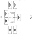
- Fig. 8 illustrates a block diagram of an exemplary mobile station, according to an exemplary embodiment.
- an uplink control method for use in a wireless communication system based on multiple carriers referred to herein as a multicarrier communication system.
- the multicarrier communication system may include a network side, such as a base station (BS), a Node B defined in the Universal Mobile Telecommunications System (UMTS) standard, an E-Node B defined in the 3rd Generation Partnership Project (3GPP) long term evolution (LTE) system, or an access point (AP), and one or more user terminals, such as mobile stations (MSs).
- the network side may wirelessly communicate with the user terminals on one or more of the multiple carriers.
- the multicarrier communication system is an IEEE standard 802.16m based communication system including at least one base station and one mobile station.
- each of the multiple carriers may be a primary carrier or a secondary carrier.
- a primary carrier may be also referred to as a fully configured carrier, and is typically used to transmit both control information and data.
- a secondary carrier may be also referred to as a partially configured carrier, and is typically used to only transmit data.
- the multicarrier communication system may have one or more primary carriers and one or more secondary carriers.
- an uplink control structure based on which the mobile station may perform random access operations, e.g., uplink ranging operations, with the base station.
- ranging may be an uplink procedure performed by the mobile station to maintain quality of communication between the mobile station and the base station.
- the base station may process the received ranging signal to calculate various communication parameters, such as a timing offset, a frequency offset, and a power strength. Based on the calculation, the base station may indicate to the mobile station any adjustments the mobile station needs to make in order to maintain the quality of the communication, such as an adjustment in transmitting power or an adjustment in transmission timing.
- the mobile station may perform different types of random access operations, such as initial ranging, periodic ranging, handover ranging, or bandwidth request ranging.
- the mobile station may perform initial ranging when it performs network entry. The mobile station performs network entry at the time it is turned on.
- the mobile station may perform periodic ranging because, e.g., a location of the mobile station may be changed and the mobile station needs to make adjustments in transmitting power and/or transmission timing in order to maintain communication quality.
- the mobile station may perform handover ranging when it performs handover between different primary carriers, which may belong to the same base station or a different base station.
- the mobile station may perform bandwidth request ranging when it wants to request bandwidth resources from the base station.
- the uplink control structure may include an initial ranging channel allocated for the mobile station to perform initial ranging, a periodic ranging channel allocated for the mobile station to perform periodic ranging, a handover ranging channel allocated for the mobile station to perform handover ranging, and/or a bandwidth request ranging channel allocated for the mobile station to perform bandwidth request ranging.
- Fig. 2 illustrates an uplink control method 200 for use in the above-described multicarrier communication system, according to an exemplary embodiment.
- a frame structure 202 is shown for a primary carrier CH0, a first secondary carrier CH1, and a second secondary carrier CH2 of the multiple carriers.
- the frame structure 202 may include a plurality of super-frames, such as first and second super-frames 204 and 206.
- Each of the plurality of super-frames may further include a plurality of frames.
- the multicarrier communication system is an IEEE standard 802.16m based communication system.
- each of the plurality of super-frames includes four frames 212, 214, 216, and 218.
- Each of the frames may further include a plurality of downlink and uplink sub-frames (not shown).
- a synchronization control channel (SCH) 222 and a broadcast control channel (BCH) 224 may be only allocated to the primary carriers such as the primary carrier CH0, and a unicast service control channel (USCCH) 226 may be allocated to the primary and secondary carriers such as the primary carrier CH0 and the secondary carriers CH1 and CH2.
- SCH synchronization control channel
- BCH broadcast control channel
- USB unicast service control channel
- an initial random access channel e.g., an initial ranging channel 232
- an initial ranging channel 232 may be only allocated to the primary carriers such as the primary carrier CH0. It is not necessary to allocate an initial ranging channel to the secondary carriers such as the secondary carrier CH1 or CH2. As a result, the mobile station may perform network entry and initial uplink synchronization on the primary carrier CH0. As noted above, the SCH 222 may be only allocated to a primary carrier.
- the mobile station may skip that carrier and proceed with scanning of frequencies, until the mobile station detects a primary carrier and determines to use the detected primary carrier to perform initial uplink synchronization, such as the primary carrier CH0. The mobile station may then perform network entry on the primary carrier CH0.
- a carrier without the SCH 222 such as the secondary carrier CH1 or CH2
- the mobile station may skip that carrier and proceed with scanning of frequencies, until the mobile station detects a primary carrier and determines to use the detected primary carrier to perform initial uplink synchronization, such as the primary carrier CH0.
- the mobile station may then perform network entry on the primary carrier CH0.
- the initial ranging channel 232 is transmitted on the primary carrier CH0 once in each of the plurality of super-frames.
- the initial ranging channel 232 may be transmitted in a first uplink sub-frame in the frame 212.
- a location of the initial ranging channel 232 in a super-frame may be indicated by the BCH 224 in that super-frame.
- the BCH 224 is only allocated to the primary carriers such as the primary carrier CH0.
- the mobile station may proceed with reading the BCH 224 in the super-frame 204 to obtain information regarding a location of the initial ranging channel 232 in the super-frame 204.
- the mobile station may perform network entry and achieve synchronization using the initial ranging channel 232 on the primary carrier CH0, and avoid initial ranging on a secondary carrier with possibly incorrect synchronization.
- the mobile station may still request support from additional carriers after performing network entry.
- Fig. 3 illustrates an uplink control method 300 for use in the above-described multicarrier communication system, according to an exemplary embodiment.
- a frame structure 302 is shown for the primary carrier CH0, the first secondary carrier CH1, and the second secondary carrier CH2 of the multiple carriers.
- the frame structure 302 may include a plurality of super-frames, such as first and second super-frames 304 and 306.
- Each of the plurality of super-frames may further include a plurality of frames.
- the multicarrier communication system is an IEEE standard 802.16m based communication system.
- each of the plurality of super-frames includes four frames 312, 314, 316, and 318.
- Each of the frames may further include a plurality of downlink and uplink sub-frames (not shown).
- a synchronization control channel (SCH) 322, a broadcast control channel (BCH) 324, and an initial ranging channel 332 may be only allocated to the primary carriers such as the primary carrier CH0, and a unicast service control channel (USCCH) 326 may be allocated to the primary and secondary carriers such as the primary carrier CH0 and the secondary carriers CH1 and CH2, as described above.
- SCH synchronization control channel
- BCH broadcast control channel
- USB unicast service control channel
- a periodic random access channel e.g., a periodic ranging channel 334
- the primary carriers such as the primary carrier CH0
- the secondary carriers such as the secondary carriers CH1 and CH2.
- the mobile station may switch between the primary carrier CH0 and the secondary carrier CH1 or CH2. Due to different center frequencies of carriers, the periodic ranging channel 334 may be allocated to both the primary and secondary carriers, to support the mobile station to perform periodic uplink synchronization.
- the mobile station may, if it is operating on the primary carrier CH0, perform periodic uplink synchronization on the primary carrier CH0, or if it is operating on the secondary carrier CH1 or CH2, perform periodic uplink synchronization on the secondary carrier CH1 or CH2.
- the base station may acquire channel information from the mobile station or prepare statistics of mobile station conditions. For example, the base station may calculate a load condition for the mobile station. Accordingly, based on the load condition, the base station may re-configure allocation of the periodic ranging channel 334 for the carrier on which the mobile station performs the periodic uplink synchronization, by, e.g., changing a bandwidth, a periodic cycle, or a location of the periodic ranging channel 334.
- predetermined allocation patterns may be used for the periodic ranging channel 334, to reduce overhead of signaling negotiations.
- a first allocation pattern is used for the primary carrier CH0, where the periodic ranging channel 334 is allocated to a first one of the four frames, i.e., the frame 312, in each of the super-frames 304 and 306.
- a second allocation pattern and a third allocation pattern are used for the secondary carrier CH1, in which the periodic ranging channel 334 is allocated to a fourth one of the four frames, i.e., the frame 318, in the super-frame 304, and is allocated to each of the four frames in the super-frame 306.
- the third allocation pattern and a fourth allocation pattern are used for the secondary carrier CH2, in which the periodic ranging channel 334 is allocated to each of the four frames in the super-frame 304, and is also allocated to each of the four frames in the super-frame 306 but with an increased bandwidth, represented by the increased height of the small block representing the periodic ranging channel 334.
- the mobile station may perform network entry on the primary carrier CH0 and achieve synchronization using the initial ranging channel 332, as described above.
- the mobile station may perform adjustments by periodic ranging on the periodic ranging channel 334 without performing network re-entry.
- a handover random access channel e.g., a handover ranging channel (not shown) may be only allocated to the primary carriers, such as the primary carrier CH0.
- the mobile station performs a handover when it switches between different primary carriers, which may belong to the same base station or a different base station.
- the mobile station may perform a handover to a primary carrier by performing handover ranging on the handover ranging channel allocated to the primary carrier.
- locations of the handover ranging channel may be changed in the super-frames at a relatively low frequency. For example, a location of the handover ranging channel in a super-frame may be indicated by the BCH in that super-frame.
- Fig. 4 illustrates an uplink control method 400 for use in the above-described multicarrier communication system, according to an exemplary embodiment.
- a frame structure 402 is shown for the primary carrier CH0, the first secondary carrier CH1, and the second secondary carrier CH2 of the multiple carriers.
- the frame structure 402 may include a plurality of super-frames, such as first and second super-frames 404 and 406.
- Each of the plurality of super-frames may further include a plurality of frames.
- the multicarrier communication system is an IEEE standard 802.16m based communication system.
- each of the plurality of super-frames includes four frames 412, 414, 416, and 418.
- Each of the frames may further include a plurality of downlink and uplink sub-frames (not shown).
- a synchronization control channel (SCH) 422, a broadcast control channel (BCH) 424, and an initial ranging channel 432 may be only allocated to the primary carriers such as the primary carrier CH0, and a unicast service control channel (USCCH) 426 and a periodic ranging channel 434 may be allocated to the primary and secondary carriers, such as the primary carrier CH0 and the secondary carriers CH1 and CH2, as described above.
- SCH synchronization control channel
- BCH broadcast control channel
- an initial ranging channel 432 may be only allocated to the primary carriers such as the primary carrier CH0
- a unicast service control channel (USCCH) 426 and a periodic ranging channel 434 may be allocated to the primary and secondary carriers, such as the primary carrier CH0 and the secondary carriers CH1 and CH2, as described above.
- a bandwidth request (BR) random access channel e.g., a bandwidth request (BR) ranging channel 436
- BR bandwidth request
- a bandwidth request (BR) ranging channel 436 may be only allocated to the primary carriers such as the primary carrier CH0.
- the mobile station may send bandwidth request signaling to the base station on the bandwidth request ranging channel 436.
- the mobile station may simultaneously establish several communication connections on different carriers including ones of the primary and secondary carriers.
- the bandwidth request ranging channel 436 were allocated to both primary and secondary carriers, it may cause resource overhead and, in addition, the base station may need to handle bandwidth requests from each one of the different carriers, which may increase complexity of the base station. Therefore, in exemplary embodiments consistent with the present invention, the bandwidth request ranging channel 436 may be only allocated to the primary carriers, and its location in the super-frames is dynamic and may be indicated by the USCCH 426.
- the mobile station may send a bandwidth request for one or more communication connections, including communication connections established on secondary carriers, on a primary carrier. For example, a bandwidth request for communication connections established on the primary carrier CH0 and the secondary carriers CH1 and CH2 may be sent on the primary carrier CH0.
- the base station may allocate uplink resources for a carrier or a combination of multiple carriers, while control information regarding the resource allocation may be transmitted on the primary carrier.
- the mobile station may send bandwidth request signaling using an aggregate request method or a separate request method, as described below.
- Fig. 5 illustrates an aggregate request method 500 for a mobile station 502 to request bandwidth allocation from a base station 504, according to an exemplary embodiment.
- the mobile station 502 may have established a plurality of communication connections with the base station 504. If the communication connections correspond to a same quality of service (QoS) class, the mobile station 502 may group the communication connections together and calculate a total bandwidth required for the communication connections. The mobile station 502 may then send to the base station 504 an aggregate request for the total required bandwidth.
- QoS quality of service
- the mobile station 502 may have first and second communication connections with the base station 504, the first and second communication connections corresponding to the same QoS class. If the mobile station 502 decides that the first communication connection needs a bandwidth of 10 kilobit per second (kbps) and the second communication connection needs a bandwidth of 20 kbps, the mobile station 502 may calculate a total bandwidth of 30 kbps required for the first and second communication connections. The mobile station 502 may then send to the base station 504 an aggregate request for the total bandwidth of 30 kbps.
- kbps kilobit per second
- the mobile station 502 may send to the base station 504 a bandwidth request (BR) indicator 510, to indicate that the mobile station 502 needs bandwidth allocation for the plurality of communication connections.
- the BR indicator 510 may be a code-division-multiple-access (CDMA) code.
- CDMA-allocation-IE CDMA allocation information element
- the mobile station 502 may further send to the base station 504 BR signaling 514, which includes information regarding a group connection identification (CID) and the total bandwidth required for the communication connections.
- the BR signaling 514 may be a specific message or have a defined header format.
- the base station 504 may grant bandwidth allocation for the communication connections (516).
- Fig. 6 illustrates a separate request method 600 for a mobile station 602 to request bandwidth allocation from a base station 604, according to an exemplary embodiment.
- the mobile station 602 may have established a plurality of communication connections with the base station 604. If the communication connections correspond to different QoS classes, the mobile station 602 may group ones of the communication connections that correspond to a same QoS class together, to generate a plurality of groups of communication connections. The mobile station 602 may calculate a total bandwidth required for each of the groups of communication connections. The mobile station 602 may then send to the base station 604 separate requests each for one of the groups of communication connections.
- the mobile station 602 may send to the base station 604 a bandwidth request (BR) indicator 610, to indicate that the mobile station 602 needs bandwidth allocation for the plurality of communication connections.
- the BR indicator 610 may be a code-division-multiple-access (CDMA) code.
- CDMA-allocation-IE CDMA allocation information element
- the mobile station 602 may then send to the base station 604 BR signaling 614, which includes information regarding multiple-bandwidth-request (multi-BR) signaling for the groups of communication connections.
- the multi-BR signaling may be multiple specific messages or have defined header formats.
- the base station 604 may send a grant message 616 to the mobile station 602, to indicate that the multi-BR signaling has been granted and where bandwidth resources have been allocated for the mobile station 602 to send multi-BR signaling.
- the mobile station 602 may further send multi-BR signaling 618 to the base station 604, the multi-BR signaling 618 including information regarding a group connection identification (CID) and a total bandwidth required for each of the groups of communication connections.
- the base station 604 may grant bandwidth allocation for the groups of communication connections (620).
- Fig. 7 illustrates a block diagram of an exemplary base station (BS) 700, according to an exemplary embodiment.
- the base station 700 may be the base station noted above in any of Figs. 2-6 .
- the base station 700 may include one or more of the following components: at least one central processing unit (CPU) 702 configured to execute computer program instructions to perform various processes and methods, random access memory (RAM) 704 and read only memory (ROM) 706 configured to access and store information and computer program instructions, storage 708 to store data and information, databases 710 to store tables, lists, or other data structures, I/O devices 712, interfaces 714, antennas 716, etc.
- CPU central processing unit
- RAM random access memory
- ROM read only memory
- storage 708 to store data and information
- databases 710 to store tables, lists, or other data structures
- I/O devices 712, interfaces 714, antennas 716 etc.
- Fig. 8 illustrates a block diagram of an exemplary mobile station (MS) 800, according to an exemplary embodiment.
- the mobile station 800 may be the mobile station noted above in any of Figs. 2-6 .
- the mobile station 800 may include one or more of the following components: at least one central processing unit (CPU) 802 configured to execute computer program instructions to perform various processes and methods, random access memory (RAM) 804 and read only memory (ROM) 806 configured to access and store information and computer program instructions, storage 808 to store data and information, databases 810 to store tables, lists, or other data structures, I/O devices 812, interfaces 814, antennas 816, etc.
- CPU central processing unit
- RAM random access memory
- ROM read only memory
- storage 808 to store data and information
- databases 810 to store tables, lists, or other data structures
- I/O devices 812, interfaces 814, antennas 816 etc.
Landscapes
- Engineering & Computer Science (AREA)
- Signal Processing (AREA)
- Computer Networks & Wireless Communication (AREA)
- Quality & Reliability (AREA)
- Mobile Radio Communication Systems (AREA)
Abstract
Description
- This application is based upon and claims the benefit of priority from
U.S. Provisional Patent Application No. 61/071,551, filed May 5, 2008 - This invention relates to systems and methods for multicarrier uplink control.
- Wireless communication systems based on a multicarrier scheme, such as orthogonal frequency-division multiplexing (OFDM) based communication systems, are gaining worldwide popularity due to their broad applications. The multicarrier scheme allows a multicarrier communication system to operate on multiple carriers including continuous and discontinuous carriers. Each of the multiple carriers corresponds to a relatively narrow frequency band, and may have a different bandwidth.
- Traditionally, a separate fast Fourier transform (FFT) and radio frequency (RF) module may be used for each band, and a medium access control (MAC) module may then be used in the multicarrier communication system to support multicarrier functionalities. Based on different capabilities of different user terminals, a network side, such as a base station (BS), a Node B defined in a Universal Mobile Telecommunications System (UMTS) standard, or an access point (AP), may serve different user terminals with different bandwidths. For example, based on the multicarrier scheme, the base station may flexibly use available bandwidth resources to achieve high throughput and capacity.
- For controlling and utilizing the multiple carriers, each of the multiple carriers may be classified as a primary carrier, also known as a fully configured carrier, or a secondary carrier, also known as a partially configured carrier. For example, a primary carrier is typically used to transmit both control information and data, and a secondary carrier is typically used to only transmit data. Depending on characteristics of transmission of control information and data, a downlink control method may use different downlink control structures for a primary carrier and a secondary carrier.
-
Fig. 1 illustrates a conventionaldownlink control method 100 for use in a multicarrier communication system based on IEEE standard 802.16m. For convenience of illustration, aframe structure 102 is shown for a primary carrier CH0, a first secondary carrier CH1, and a second secondary carrier CH2 of the multiple carriers of the multicarrier system. For example, theframe structure 102 may include a plurality of super-frames, such as first and second super-frames 104 and 106. Each of the plurality of super-frames may further include a plurality of frames. Based on the IEEE standard 802.16m, each of the plurality of super-frames may include fourframes - For example, the
SCH 122 may provide a reference signal for time, frequency, frame synchronization, and base station identification. TheSCH 122 may be only allocated to the primary carrier CH0. In addition, theSCH 122 may be transmitted on the primary carrier CH0 every one or more frames, such as every four frames as shown inFig. 1 , and a location of theSCH 122 may be fixed in each of the plurality of super-frames. The secondary carriers CH1 and CH2 may share theSCH 122 with the primary channel CH0. - Also for example, the BCH 124 may provide system configuration information and broadcast information, such as neighbor base station information, paging information, etc. The BCH 124 may be only allocated to the primary carrier CH0. In addition, the BCH 124 may be transmitted on the primary carrier CH0 every one or more frames, such as every four frames as shown in
Fig. 1 , and a location of the BCH 124 may be fixed in each of the plurality of super-frames. The secondary carriers CH1 and CH2 may share theBCH 124 with the primary channel CH0. - Further for example, the USCCH 126 may provide resource allocation for unicast services. The USCCH 126 may be allocated to the primary carrier CH0 and the secondary carriers CH1 and CH2. In addition, the USCCH 126 and the
SCH 122 are transmitted at different times, and the USCCH 126 and the BCH 124 are also transmitted at different times. - The features of the invention are defined in the claims. However, where a claim contains multiple features, it must be understood that any one of those features may be applied independently of the others. Accordingly, no assumption is to be drawn that the claims define strict combinations of features that must be grouped together for technical reasons.
- In accordance with the invention, there is provided an uplink control method for use in a communication system based on multiple carriers, the method comprising: allocating different types of random access channels for different types of uplink operations.
- Optionally, the multiple carriers include one or more primary carriers and one or more secondary carriers, the method further comprising: allocating an initial random access channel only to each of the primary carriers; wherein the initial random access channel is configured for a user terminal in the communication system to perform initial uplink synchronization.
- Optionally, the method further comprises: transmitting, on a first one of the primary carriers, the initial random access channel at least once in each of a plurality of super-frames; wherein a location of the initial random access channel is indicated by a broadcast control channel (BCH) allocated to the first one of the primary carriers.
- Optionally, the multiple carriers include one or more primary carriers and one or more secondary carriers, the method further comprising: allocating a periodic random access channel to each of the primary and secondary carriers; wherein the periodic random access channel is configured for a user terminal in the communication system to perform periodic uplink synchronization.
- Optionally, the method further comprises: transmitting, on a first one of the primary and secondary carriers, the periodic random access channel at least once in each of a plurality of super-frames.
- Optionally, the method further comprises: transmitting, on the first one of the primary and secondary carriers, the periodic random access channel in first and second ones of the plurality of super-frames based on first and second predetermined allocation patterns, respectively, the first and second allocation patterns being different.
- Optionally, the multiple carriers include one or more primary carriers and one or more secondary carriers, the method further comprising: allocating a handover random access channel only to each of the primary carriers; wherein the handover random access channel is configured for a user terminal in the communication system to perform handover.
- Optionally, the method further comprises: transmitting, on a first one of the primary carriers, the handover random access channel in a plurality of super-frames; wherein a location of the handover random access channel is indicated by a broadcast control channel (BCH) allocated to the first one of the primary carriers.
- Optionally, the multiple carriers include one or more primary carriers and one or more secondary carriers, the method further comprising: allocating a bandwidth request random access channel only to each of the primary carriers; wherein the bandwidth request random access channel is configured for a user terminal in the communication system to perform bandwidth request.
- Optionally, the method further comprises: transmitting, on a first one of the primary carriers, the bandwidth request random access channel in a plurality of super-frames; wherein a location of the bandwidth request random access channel is indicated by a unicast service control channel (USCCH) allocated to the first one of the primary carriers.
- Also in accordance with the invention, there is provided a base station configured to: allocate different types of random access channels for different types of uplink operations.
- Optionally, the base station operates on multiple carriers including one or more primary carriers and one or more secondary carriers, the base station being further configured to: allocate an initial random access channel only to each of the primary carriers; wherein the initial random access channel is configured for a user terminal to perform initial uplink synchronization with the base station.
- Optionally, the base station operates on multiple carriers including one or more primary carriers and one or more secondary carriers, the base station being further configured to: allocate a periodic random access channel to each of the primary and secondary carriers; wherein the periodic random access channel is configured for a user terminal to perform periodic uplink synchronization with the base station.
- Optionally, the base station operates on multiple carriers including one or more primary carriers and one or more secondary carriers, the base station being further configured to: allocate a handover random access channel only to each of the primary carriers; wherein the handover random access channel is configured for a user terminal to perform handover to the base station.
- Optionally, the base station operates on multiple carriers including one or more primary carriers and one or more secondary carriers, the base station being further configured to: allocate a bandwidth request random access channel only to each of the primary carriers; wherein the bandwidth request random access channel is configured for a user terminal to request bandwidth allocation from the base station.
- Further in accordance with the invention, there is provided a mobile station configured to: perform different types of uplink operations on different types of random access channels.
- Optionally, the mobile station communicates with a base station based on multiple carriers, including one or more primary carriers and one or more secondary carriers, the mobile station being further configured to: perform initial uplink synchronization with the base station on an initial random access channel; wherein the initial random access channel is allocated to one of the primary carriers.
- Optionally, the mobile station communicates with a base station based on multiple carriers, including one or more primary carriers and one or more secondary carriers, the mobile station being further configured to: perform periodic uplink synchronization with the base station on a periodic random access channel; wherein the periodic random access channel is allocated to one of the primary or secondary carriers.
- Optionally, the mobile station communicates with a base station based on multiple carriers, including one or more primary carriers and one or more secondary carriers, the mobile station being further configured to: perform handover to the base station on a handover random access channel; wherein the handover random access channel is allocated to one of the primary carriers.
- Optionally, the mobile station communicates with a base station based on multiple carriers, including one or more primary carriers and one or more secondary carriers, the mobile station being further configured to: perform a bandwidth allocation request to the base station on a bandwidth request random access channel; wherein the bandwidth request random access channel is allocated to one of the primary carriers.
- Further in accordance with the invention, there is provided a bandwidth request method for use in a communication system based on multiple carriers, the method comprising: determining, for communication connections for which a bandwidth request is to be sent, a quality of service (QoS) of each of the communication connections; and sending the bandwidth request based on the determination.
- Optionally, when it is determined that the communication connections have a same QoS class, the method further comprises: calculating a total bandwidth required for the communication connections; and sending an aggregate request as the bandwidth request for the total bandwidth.
- Optionally, when it is determined that the communication connections have different QoS classes, the method further comprises: separating the communication connections into a plurality of groups of communication connections, each of the groups having a same QoS class; calculating a total bandwidth required for each of the groups of communication connections, to thereby generate a plurality of calculated bandwidths; and sending separate requests as the bandwidth request when a random access to one of the multiple carriers is achieved, each of the separate requests for one of the plurality of calculated bandwidths.
- Further in accordance with the invention, there is provided a mobile station configured to: determine, for communication connections for which a bandwidth request is to be sent, a quality of service (QoS) of each of the communication connections; and send the bandwidth request based on the determination.
- Optionally, when it is determined that the communication connections have a same QoS class, the mobile station is further configured to: calculate a total bandwidth required for the communication connections; and send an aggregate request as the bandwidth request for the total bandwidth.
- Optionally, when it is determined that the communication connections have different QoS classes, the mobile station is further configured to: separate the communication connections into a plurality of groups of communication connections, each of the groups having a same QoS class; calculate a total bandwidth required for each of the groups of communication connections, to thereby generate a plurality of calculated bandwidths; and send separate requests as the bandwidth request when a random access to a carrier is achieved, each of the separate requests for one of the plurality of calculated bandwidths.
- It is to be understood that both the foregoing general description and the following detailed description are exemplary and explanatory only and are not restrictive of the invention, as claimed.
- The accompanying drawings, which are incorporated in and constitute a part of this specification, illustrate embodiments of the invention and, together with the description, serve to explain the principles of the invention.
-
Fig. 1 illustrates a conventional downlink control method for use in a multicarrier communication system. -
Fig. 2 illustrates an uplink control method for use in a multicarrier communication system, according to an exemplary embodiment. -
Fig. 3 illustrates an uplink control method for use in a multicarrier communication system, according to an exemplary embodiment. -
Fig. 4 illustrates an uplink control method for use in a multicarrier communication system, according to an exemplary embodiment. -
Fig. 5 illustrates an aggregate request method for a mobile station to request bandwidth allocation from a base station, according to an exemplary embodiment. -
Fig. 6 illustrates a separate request method for a mobile station to request bandwidth allocation from a base station, according to an exemplary embodiment. -
Fig. 7 illustrates a block diagram of an exemplary base station, according to an exemplary embodiment. -
Fig. 8 illustrates a block diagram of an exemplary mobile station, according to an exemplary embodiment. - Reference will now be made in detail to exemplary embodiments, examples of which are illustrated in the accompanying drawings. The following description refers to the accompanying drawings in which the same numbers in different drawings represent the same or similar elements unless otherwise represented. The implementations set forth in the following description of exemplary embodiments consistent with the present invention do not represent all implementations consistent with the invention. Instead, they are merely examples of systems and methods consistent with aspects related to the invention as recited in the appended claims.
- In exemplary embodiments consistent with the present invention, there is provided an uplink control method for use in a wireless communication system based on multiple carriers, referred to herein as a multicarrier communication system. Each of the multiple carriers corresponds to a frequency band, and may have a different bandwidth. The multicarrier communication system may include a network side, such as a base station (BS), a Node B defined in the Universal Mobile Telecommunications System (UMTS) standard, an E-Node B defined in the 3rd Generation Partnership Project (3GPP) long term evolution (LTE) system, or an access point (AP), and one or more user terminals, such as mobile stations (MSs). The network side may wirelessly communicate with the user terminals on one or more of the multiple carriers. For illustrative purposes only, it is assumed that the multicarrier communication system is an IEEE standard 802.16m based communication system including at least one base station and one mobile station.
- In exemplary embodiments consistent with the present invention, each of the multiple carriers may be a primary carrier or a secondary carrier. A primary carrier may be also referred to as a fully configured carrier, and is typically used to transmit both control information and data. A secondary carrier may be also referred to as a partially configured carrier, and is typically used to only transmit data. The multicarrier communication system may have one or more primary carriers and one or more secondary carriers.
- In exemplary embodiments consistent with the present invention, there is provided an uplink control structure, based on which the mobile station may perform random access operations, e.g., uplink ranging operations, with the base station. For example, ranging may be an uplink procedure performed by the mobile station to maintain quality of communication between the mobile station and the base station. When the base station receives a ranging signal from the mobile station, the base station may process the received ranging signal to calculate various communication parameters, such as a timing offset, a frequency offset, and a power strength. Based on the calculation, the base station may indicate to the mobile station any adjustments the mobile station needs to make in order to maintain the quality of the communication, such as an adjustment in transmitting power or an adjustment in transmission timing.
- In exemplary embodiments consistent with the present invention, the mobile station may perform different types of random access operations, such as initial ranging, periodic ranging, handover ranging, or bandwidth request ranging. For example, the mobile station may perform initial ranging when it performs network entry. The mobile station performs network entry at the time it is turned on. Also for example, the mobile station may perform periodic ranging because, e.g., a location of the mobile station may be changed and the mobile station needs to make adjustments in transmitting power and/or transmission timing in order to maintain communication quality. Further for example, the mobile station may perform handover ranging when it performs handover between different primary carriers, which may belong to the same base station or a different base station. As another example, the mobile station may perform bandwidth request ranging when it wants to request bandwidth resources from the base station.
- In exemplary embodiments consistent with the present invention, different types of random access channels, e.g., different types of ranging channels, may be allocated for different types of ranging operations. For example, the uplink control structure may include an initial ranging channel allocated for the mobile station to perform initial ranging, a periodic ranging channel allocated for the mobile station to perform periodic ranging, a handover ranging channel allocated for the mobile station to perform handover ranging, and/or a bandwidth request ranging channel allocated for the mobile station to perform bandwidth request ranging. These ranging channels and their allocation will be described in detail below.
-
Fig. 2 illustrates anuplink control method 200 for use in the above-described multicarrier communication system, according to an exemplary embodiment. For convenience of illustration, aframe structure 202 is shown for a primary carrier CH0, a first secondary carrier CH1, and a second secondary carrier CH2 of the multiple carriers. For example, theframe structure 202 may include a plurality of super-frames, such as first andsecond super-frames frames - In addition, a synchronization control channel (SCH) 222 and a broadcast control channel (BCH) 224 may be only allocated to the primary carriers such as the primary carrier CH0, and a unicast service control channel (USCCH) 226 may be allocated to the primary and secondary carriers such as the primary carrier CH0 and the secondary carriers CH1 and CH2.
- In exemplary embodiments consistent with the present invention, an initial random access channel, e.g., an initial ranging
channel 232, may be only allocated to the primary carriers such as the primary carrier CH0. It is not necessary to allocate an initial ranging channel to the secondary carriers such as the secondary carrier CH1 or CH2. As a result, the mobile station may perform network entry and initial uplink synchronization on the primary carrier CH0. As noted above, theSCH 222 may be only allocated to a primary carrier. Therefore, if the mobile station, during its network entry, detects a carrier without theSCH 222, such as the secondary carrier CH1 or CH2, the mobile station may skip that carrier and proceed with scanning of frequencies, until the mobile station detects a primary carrier and determines to use the detected primary carrier to perform initial uplink synchronization, such as the primary carrier CH0. The mobile station may then perform network entry on the primary carrier CH0. - In one exemplary embodiment, the initial ranging
channel 232 is transmitted on the primary carrier CH0 once in each of the plurality of super-frames. For example, the initial rangingchannel 232 may be transmitted in a first uplink sub-frame in theframe 212. Furthermore, a location of the initial rangingchannel 232 in a super-frame may be indicated by theBCH 224 in that super-frame. As noted above, theBCH 224 is only allocated to the primary carriers such as the primary carrier CH0. Once the mobile station detects on the primary carrier CH0 theSCH 222 in a super-frame, e.g., the super-frame 204, the mobile station may proceed with reading theBCH 224 in the super-frame 204 to obtain information regarding a location of the initial rangingchannel 232 in thesuper-frame 204. As a result, the mobile station may perform network entry and achieve synchronization using the initial rangingchannel 232 on the primary carrier CH0, and avoid initial ranging on a secondary carrier with possibly incorrect synchronization. The mobile station may still request support from additional carriers after performing network entry. -
Fig. 3 illustrates anuplink control method 300 for use in the above-described multicarrier communication system, according to an exemplary embodiment. For convenience of illustration, aframe structure 302 is shown for the primary carrier CH0, the first secondary carrier CH1, and the second secondary carrier CH2 of the multiple carriers. For example, theframe structure 302 may include a plurality of super-frames, such as first andsecond super-frames frames - In addition, a synchronization control channel (SCH) 322, a broadcast control channel (BCH) 324, and an initial ranging
channel 332 may be only allocated to the primary carriers such as the primary carrier CH0, and a unicast service control channel (USCCH) 326 may be allocated to the primary and secondary carriers such as the primary carrier CH0 and the secondary carriers CH1 and CH2, as described above. - In exemplary embodiments consistent with the present invention, a periodic random access channel, e.g., a periodic ranging
channel 334, may be allocated to the primary carriers, such as the primary carrier CH0, and the secondary carriers, such as the secondary carriers CH1 and CH2. For example, the mobile station may switch between the primary carrier CH0 and the secondary carrier CH1 or CH2. Due to different center frequencies of carriers, the periodic rangingchannel 334 may be allocated to both the primary and secondary carriers, to support the mobile station to perform periodic uplink synchronization. As a result, the mobile station may, if it is operating on the primary carrier CH0, perform periodic uplink synchronization on the primary carrier CH0, or if it is operating on the secondary carrier CH1 or CH2, perform periodic uplink synchronization on the secondary carrier CH1 or CH2. - In addition, the base station may acquire channel information from the mobile station or prepare statistics of mobile station conditions. For example, the base station may calculate a load condition for the mobile station. Accordingly, based on the load condition, the base station may re-configure allocation of the periodic ranging
channel 334 for the carrier on which the mobile station performs the periodic uplink synchronization, by, e.g., changing a bandwidth, a periodic cycle, or a location of the periodic rangingchannel 334. - In one exemplary embodiment, predetermined allocation patterns may be used for the periodic ranging
channel 334, to reduce overhead of signaling negotiations. For example, referring toFig. 3 , a first allocation pattern is used for the primary carrier CH0, where the periodic rangingchannel 334 is allocated to a first one of the four frames, i.e., theframe 312, in each of the super-frames 304 and 306. Also for example, a second allocation pattern and a third allocation pattern are used for the secondary carrier CH1, in which the periodic rangingchannel 334 is allocated to a fourth one of the four frames, i.e., theframe 318, in the super-frame 304, and is allocated to each of the four frames in thesuper-frame 306. Further for example, the third allocation pattern and a fourth allocation pattern are used for the secondary carrier CH2, in which the periodic rangingchannel 334 is allocated to each of the four frames in the super-frame 304, and is also allocated to each of the four frames in the super-frame 306 but with an increased bandwidth, represented by the increased height of the small block representing the periodic rangingchannel 334. - As a result, for example, the mobile station may perform network entry on the primary carrier CH0 and achieve synchronization using the initial ranging
channel 332, as described above. When the base station or the mobile station decides that the secondary carrier CH1 or CH2 is needed to serve the mobile station, the mobile station may perform adjustments by periodic ranging on the periodic rangingchannel 334 without performing network re-entry. - In exemplary embodiments consistent with the present invention, a handover random access channel, e.g., a handover ranging channel (not shown), may be only allocated to the primary carriers, such as the primary carrier CH0. The mobile station performs a handover when it switches between different primary carriers, which may belong to the same base station or a different base station. The mobile station may perform a handover to a primary carrier by performing handover ranging on the handover ranging channel allocated to the primary carrier. In addition, locations of the handover ranging channel may be changed in the super-frames at a relatively low frequency. For example, a location of the handover ranging channel in a super-frame may be indicated by the BCH in that super-frame.
-
Fig. 4 illustrates anuplink control method 400 for use in the above-described multicarrier communication system, according to an exemplary embodiment. For convenience of illustration, aframe structure 402 is shown for the primary carrier CH0, the first secondary carrier CH1, and the second secondary carrier CH2 of the multiple carriers. For example, theframe structure 402 may include a plurality of super-frames, such as first andsecond super-frames frames - In addition, a synchronization control channel (SCH) 422, a broadcast control channel (BCH) 424, and an initial ranging
channel 432 may be only allocated to the primary carriers such as the primary carrier CH0, and a unicast service control channel (USCCH) 426 and a periodic rangingchannel 434 may be allocated to the primary and secondary carriers, such as the primary carrier CH0 and the secondary carriers CH1 and CH2, as described above. - In exemplary embodiments consistent with the present invention, a bandwidth request (BR) random access channel, e.g., a bandwidth request (BR) ranging channel 436, may be only allocated to the primary carriers such as the primary carrier CH0. When the mobile station needs bandwidth resources, the mobile station may send bandwidth request signaling to the base station on the bandwidth request ranging channel 436.
- For example, the mobile station may simultaneously establish several communication connections on different carriers including ones of the primary and secondary carriers. If the bandwidth request ranging channel 436 were allocated to both primary and secondary carriers, it may cause resource overhead and, in addition, the base station may need to handle bandwidth requests from each one of the different carriers, which may increase complexity of the base station. Therefore, in exemplary embodiments consistent with the present invention, the bandwidth request ranging channel 436 may be only allocated to the primary carriers, and its location in the super-frames is dynamic and may be indicated by the USCCH 426.
- In one exemplary embodiment, the mobile station may send a bandwidth request for one or more communication connections, including communication connections established on secondary carriers, on a primary carrier. For example, a bandwidth request for communication connections established on the primary carrier CH0 and the secondary carriers CH1 and CH2 may be sent on the primary carrier CH0. On the base station side, the base station may allocate uplink resources for a carrier or a combination of multiple carriers, while control information regarding the resource allocation may be transmitted on the primary carrier. In addition, the mobile station may send bandwidth request signaling using an aggregate request method or a separate request method, as described below.
-
Fig. 5 illustrates anaggregate request method 500 for amobile station 502 to request bandwidth allocation from abase station 504, according to an exemplary embodiment. For example, themobile station 502 may have established a plurality of communication connections with thebase station 504. If the communication connections correspond to a same quality of service (QoS) class, themobile station 502 may group the communication connections together and calculate a total bandwidth required for the communication connections. Themobile station 502 may then send to thebase station 504 an aggregate request for the total required bandwidth. - For example, the
mobile station 502 may have first and second communication connections with thebase station 504, the first and second communication connections corresponding to the same QoS class. If themobile station 502 decides that the first communication connection needs a bandwidth of 10 kilobit per second (kbps) and the second communication connection needs a bandwidth of 20 kbps, themobile station 502 may calculate a total bandwidth of 30 kbps required for the first and second communication connections. Themobile station 502 may then send to thebase station 504 an aggregate request for the total bandwidth of 30 kbps. - Referring to
Fig. 5 , themobile station 502 may send to the base station 504 a bandwidth request (BR)indicator 510, to indicate that themobile station 502 needs bandwidth allocation for the plurality of communication connections. For example, theBR indicator 510 may be a code-division-multiple-access (CDMA) code. Upon receiving theBR indicator 510, thebase station 504 may send to the mobile station 502 a CDMA allocation information element (CDMA-allocation-IE) 512, notifying themobile station 502 that theBR indicator 510 has been received and where bandwidth resources have been allocated for themobile station 502 to send BR signaling. Themobile station 502 may further send to thebase station 504 BR signaling 514, which includes information regarding a group connection identification (CID) and the total bandwidth required for the communication connections. The BR signaling 514 may be a specific message or have a defined header format. In response to receiving the BR signaling 514, thebase station 504 may grant bandwidth allocation for the communication connections (516). -
Fig. 6 illustrates aseparate request method 600 for amobile station 602 to request bandwidth allocation from abase station 604, according to an exemplary embodiment. For example, themobile station 602 may have established a plurality of communication connections with thebase station 604. If the communication connections correspond to different QoS classes, themobile station 602 may group ones of the communication connections that correspond to a same QoS class together, to generate a plurality of groups of communication connections. Themobile station 602 may calculate a total bandwidth required for each of the groups of communication connections. Themobile station 602 may then send to thebase station 604 separate requests each for one of the groups of communication connections. - Referring to
Fig. 6 , themobile station 602 may send to the base station 604 a bandwidth request (BR)indicator 610, to indicate that themobile station 602 needs bandwidth allocation for the plurality of communication connections. For example, theBR indicator 610 may be a code-division-multiple-access (CDMA) code. Upon receiving theBR indicator 610, thebase station 604 may send to the mobile station 602 a CDMA allocation information element (CDMA-allocation-IE) 612, notifying themobile station 602 that theBR indicator 610 has been received. Themobile station 602 may then send to thebase station 604 BR signaling 614, which includes information regarding multiple-bandwidth-request (multi-BR) signaling for the groups of communication connections. The multi-BR signaling may be multiple specific messages or have defined header formats. In response to receiving the BR signaling 614, thebase station 604 may send agrant message 616 to themobile station 602, to indicate that the multi-BR signaling has been granted and where bandwidth resources have been allocated for themobile station 602 to send multi-BR signaling. Accordingly, themobile station 602 may further sendmulti-BR signaling 618 to thebase station 604, themulti-BR signaling 618 including information regarding a group connection identification (CID) and a total bandwidth required for each of the groups of communication connections. In response to receiving themulti-BR signaling 618, thebase station 604 may grant bandwidth allocation for the groups of communication connections (620). -
Fig. 7 illustrates a block diagram of an exemplary base station (BS) 700, according to an exemplary embodiment. For example, thebase station 700 may be the base station noted above in any ofFigs. 2-6 . Referring toFig. 7 , thebase station 700 may include one or more of the following components: at least one central processing unit (CPU) 702 configured to execute computer program instructions to perform various processes and methods, random access memory (RAM) 704 and read only memory (ROM) 706 configured to access and store information and computer program instructions,storage 708 to store data and information,databases 710 to store tables, lists, or other data structures, I/O devices 712,interfaces 714,antennas 716, etc. Each of these components is well-known in the art and will not be discussed further. -
Fig. 8 illustrates a block diagram of an exemplary mobile station (MS) 800, according to an exemplary embodiment. For example, themobile station 800 may be the mobile station noted above in any ofFigs. 2-6 . Referring toFig. 8 , themobile station 800 may include one or more of the following components: at least one central processing unit (CPU) 802 configured to execute computer program instructions to perform various processes and methods, random access memory (RAM) 804 and read only memory (ROM) 806 configured to access and store information and computer program instructions,storage 808 to store data and information,databases 810 to store tables, lists, or other data structures, I/O devices 812,interfaces 814,antennas 816, etc. Each of these components is well-known in the art and will not be discussed further. - Other embodiments of the invention will be apparent to those skilled in the art from consideration of the specification and practice of the invention disclosed here. The scope of the invention is intended to cover any variations, uses, or adaptations of the invention following the general principles thereof and including such departures from the present disclosure as come within known or customary practice in the art. It is intended that the specification and examples be considered as exemplary only, with a true scope and spirit of the invention being indicated by the following claims.
- It will be appreciated that the present invention is not limited to the exact construction that has been described above and illustrated in the accompanying drawings, and that various modifications and changes can be made without departing from the scope thereof. It is intended that the scope of the invention only be limited by the appended claims.
Claims (19)
- An uplink control method for use in a communication system based on multiple carriers, the method comprising:allocating different types of random access channels for different types of uplink operations.
- The method of claim 1, wherein the multiple carriers include one or more primary carriers and one or more secondary carriers, the method further comprising:allocating an initial random access channel only to each of the primary carriers;wherein the initial random access channel is configured for a user terminal in the communication system to perform initial uplink synchronization;
said method optionally further comprising:transmitting, on a first one of the primary carriers, the initial random access channel at least once in each of a plurality of super-frames;wherein a location of the initial random access channel is indicated by a broadcast control channel (BCH) allocated to the first one of the primary carriers. - The method of claim 1 or 2, wherein the multiple carriers include one or more primary carriers and one or more secondary carriers, the method further comprising:allocating a periodic random access channel to each of the primary and secondary carriers;wherein the periodic random access channel is configured for a user terminal in the communication system to perform periodic uplink synchronization;
the method optionally further comprising:transmitting, on a first one of the primary and secondary carriers, the periodic random access channel at least once in each of a plurality of super-frames;the method optionally further comprising:transmitting, on the first one of the primary and secondary carriers, the periodic random access channel in first and second ones of the plurality of super-frames based on first and second predetermined allocation patterns, respectively, the first and second allocation patterns being different. - The method of any one of the preceding claims, wherein the multiple carriers include one or more primary carriers and one or more secondary carriers, the method further comprising:allocating a handover random access channel only to each of the primary carriers;wherein the handover random access channel is configured for a user terminal in the communication system to perform handover;
the method optionally further comprising:transmitting, on a first one of the primary carriers, the handover random access channel in a plurality of super-frames;wherein a location of the handover random access channel is indicated by a broadcast control channel (BCH) allocated to the first one of the primary carriers. - The method of any one of the preceding claims, wherein the multiple carriers include one or more primary carriers and one or more secondary carriers, the method further comprising:allocating a bandwidth request random access channel only to each of the primary carriers;wherein the bandwidth request random access channel is configured for a user terminal in the communication system to perform bandwidth request;
the method optionally further comprising:transmitting, on a first one of the primary carriers, the bandwidth request random access channel in a plurality of super-frames;wherein a location of the bandwidth request random access channel is indicated by a unicast service control channel (USCCH) allocated to the first one of the primary carriers. - A base station configured to:allocate different types of random access channels for different types of uplink operations.
- The base station of claim 6, wherein the base station operates on multiple carriers including one or more primary carriers and one or more secondary carriers, the base station being further configured to:allocate an initial random access channel only to each of the primary carriers;wherein the initial random access channel is configured for a user terminal to perform initial uplink synchronization with the base station.
- The base station of claim 6 or 7, wherein the base station operates on multiple carriers including one or more primary carriers and one or more secondary carriers, the base station being further configured to:allocate a periodic random access channel to each of the primary and secondary carriers;wherein the periodic random access channel is configured for a user terminal to perform periodic uplink synchronization with the base station.
- The base station of claim 6,7 or 8, wherein the base station operates on multiple carriers including one or more primary carriers and one or more secondary carriers, the base station being further configured to:allocate a handover random access channel only to each of the primary carriers;wherein the handover random access channel is configured for a user terminal to perform handover to the base station.
- The base station of any one of claims 6 to 9, wherein the base station operates on multiple carriers including one or more primary carriers and one or more secondary carriers, the base station being further configured to:allocate a bandwidth request random access channel only to each of the primary carriers;wherein the bandwidth request random access channel is configured for a user terminal to request bandwidth allocation from the base station.
- A mobile station configured to:perform different types of uplink operations on different types of random access channels.
- The mobile station of claim 11, wherein the mobile station communicates with a base station based on multiple carriers, including one or more primary carriers and one or more secondary carriers, the mobile station being further configured to:perform initial uplink synchronization with the base station on an initial random access channel;wherein the initial random access channel is allocated to one of the primary carriers.
- The mobile station of claim 11 or 12, wherein the mobile station communicates with a base station based on multiple carriers, including one or more primary carriers and one or more secondary carriers, the mobile station being further configured to:perform periodic uplink synchronization with the base station on a periodic random access channel;wherein the periodic random access channel is allocated to one of the primary or secondary carriers.
- The mobile station of any one of claims 11 to 13, wherein the mobile station communicates with a base station based on multiple carriers, including one or more primary carriers and one or more secondary carriers, the mobile station being further configured to:perform handover to the base station on a handover random access channel;wherein the handover random access channel is allocated to one of the primary carriers.
- The mobile station of any one of claims 11 to 14, wherein the mobile station communicates with a base station based on multiple carriers, including one or more primary carriers and one or more secondary carriers, the mobile station being further configured to:perform a bandwidth allocation request to the base station on a bandwidth request random access channel;wherein the bandwidth request random access channel is allocated to one of the primary carriers.
- A bandwidth request method for use in a communication system based on multiple carriers, the method comprising:determining, for communication connections for which a bandwidth request is to be sent, a quality of service (QoS) of each of the communication connections; andsending the bandwidth request based on the determination.
- The method of claim 16, wherein when it is determined that the communication connections have a same QoS class, the method further comprises:calculating a total bandwidth required for the communication connections; andsending an aggregate request as the bandwidth request for the total bandwidth;and/or:
wherein when it is determined that the communication connections have different QoS classes, the method further comprises:separating the communication connections into a plurality of groups of communication connections, each of the groups having a same QoS class;calculating a total bandwidth required for each of the groups of communication connections, to thereby generate a plurality of calculated bandwidths; andsending separate requests as the bandwidth request when a random access to one of the multiple carriers is achieved, each of the separate requests for one of the plurality of calculated bandwidths. - A mobile station configured to:determine, for communication connections for which a bandwidth request is to be sent, a quality of service (QoS) of each of the communication connections; andsend the bandwidth request based on the determination.
- The mobile station of claim 18, wherein when it is determined that the communication connections have a same QoS class, the mobile station is further configured to:calculate a total bandwidth required for the communication connections; andsend an aggregate request as the bandwidth request for the total bandwidth;and/or:
wherein when it is determined that the communication connections have different QoS classes, the mobile station is further configured to:separate the communication connections into a plurality of groups of communication connections, each of the groups having a same QoS class;calculate a total bandwidth required for each of the groups of communication connections, to thereby generate a plurality of calculated bandwidths; andsend separate requests as the bandwidth request when a random access to a carrier is achieved, each of the separate requests for one of the plurality of calculated bandwidths.
Priority Applications (2)
| Application Number | Priority Date | Filing Date | Title |
|---|---|---|---|
| EP14195226.7A EP2846490B1 (en) | 2008-05-05 | 2009-03-25 | Method and mobile station for bandwidth request |
| DK14195226.7T DK2846490T3 (en) | 2008-05-05 | 2009-03-25 | Bandwidth request method and mobile station |
Applications Claiming Priority (2)
| Application Number | Priority Date | Filing Date | Title |
|---|---|---|---|
| US7155108P | 2008-05-05 | 2008-05-05 | |
| US12/401,664 US8830982B2 (en) | 2008-05-05 | 2009-03-11 | System and method for multicarrier uplink control |
Related Child Applications (2)
| Application Number | Title | Priority Date | Filing Date |
|---|---|---|---|
| EP14195226.7A Division EP2846490B1 (en) | 2008-05-05 | 2009-03-25 | Method and mobile station for bandwidth request |
| EP14195226.7A Division-Into EP2846490B1 (en) | 2008-05-05 | 2009-03-25 | Method and mobile station for bandwidth request |
Publications (3)
| Publication Number | Publication Date |
|---|---|
| EP2117156A2 true EP2117156A2 (en) | 2009-11-11 |
| EP2117156A3 EP2117156A3 (en) | 2014-07-02 |
| EP2117156B1 EP2117156B1 (en) | 2018-04-25 |
Family
ID=41011862
Family Applications (2)
| Application Number | Title | Priority Date | Filing Date |
|---|---|---|---|
| EP09250841.5A Active EP2117156B1 (en) | 2008-05-05 | 2009-03-25 | Apparatuses and methods for multicarrier uplink control |
| EP14195226.7A Active EP2846490B1 (en) | 2008-05-05 | 2009-03-25 | Method and mobile station for bandwidth request |
Family Applications After (1)
| Application Number | Title | Priority Date | Filing Date |
|---|---|---|---|
| EP14195226.7A Active EP2846490B1 (en) | 2008-05-05 | 2009-03-25 | Method and mobile station for bandwidth request |
Country Status (8)
| Country | Link |
|---|---|
| US (2) | US8830982B2 (en) |
| EP (2) | EP2117156B1 (en) |
| JP (1) | JP5071989B2 (en) |
| KR (1) | KR101066935B1 (en) |
| CN (2) | CN103648178B (en) |
| DK (2) | DK2117156T3 (en) |
| ES (2) | ES2681198T3 (en) |
| TW (2) | TWI466568B (en) |
Cited By (3)
| Publication number | Priority date | Publication date | Assignee | Title |
|---|---|---|---|---|
| CN102238720A (en) * | 2010-04-29 | 2011-11-09 | 华为技术有限公司 | Carrier synchronization method, user equipment and base station |
| EP2342928A4 (en) * | 2008-11-10 | 2014-05-07 | Lg Electronics Inc | Uplink syncronization in multiple carrier system |
| EP2343935A3 (en) * | 2010-01-11 | 2014-08-27 | Acer Incorporated | Method of uplink synchronization and related communication device |
Families Citing this family (40)
| Publication number | Priority date | Publication date | Assignee | Title |
|---|---|---|---|---|
| US8761151B2 (en) | 2008-09-05 | 2014-06-24 | Blackberry Limited | Uplink control signal design for wireless system |
| US8711773B2 (en) | 2008-09-05 | 2014-04-29 | Blackberry Limited | Multi-carrier operation for wireless systems |
| US8676208B2 (en) * | 2008-06-11 | 2014-03-18 | Mediatek Inc. | Scanning and handover operation in multi-carrier wireless communications systems |
| WO2010013942A2 (en) * | 2008-07-29 | 2010-02-04 | Lg Electronics Inc. | Method for saving power in a multi-carrier wireless access system |
| US8515481B2 (en) * | 2008-09-05 | 2013-08-20 | Mediatek Inc. | Power management for multi-carrier transmission |
| US8724565B2 (en) | 2008-10-15 | 2014-05-13 | Lg Electronics Inc. | Method and apparatus for sending and receiving multi-carrier information in multi-carrier communication system |
| WO2010053253A1 (en) * | 2008-11-07 | 2010-05-14 | 엘지전자주식회사 | Method for performing bandwidth request process in wireless communication system |
| US8553634B2 (en) * | 2008-11-07 | 2013-10-08 | Lg Electronics Inc. | Method for performing bandwidth request process in wireless communication system |
| CN101742615B (en) * | 2008-11-27 | 2012-10-10 | 中兴通讯股份有限公司 | Large bandwidth multi-carrier system and broadcast information updating method thereof |
| US8320314B2 (en) | 2008-12-16 | 2012-11-27 | Lg Electronics Inc. | Method for efficiently performing initial access in a multi-carrier broadband wireless access system |
| CN101888590B (en) * | 2009-05-11 | 2014-08-13 | 中兴通讯股份有限公司 | Paging method and system of terminal in multi-carrier system |
| KR101767675B1 (en) * | 2009-05-28 | 2017-08-14 | 엘지전자 주식회사 | Method and apparatus of transmitting uplink control channel in wireless communication system |
| US8441998B2 (en) * | 2009-07-06 | 2013-05-14 | Electronics And Telecommunications Research Institute | Method of transmitting broadcast information in multiple carrier system |
| US8553645B2 (en) * | 2009-07-31 | 2013-10-08 | Motorola Mobility Llc | Method and apparatus for service continuity on a mobile communication device |
| RU2517191C2 (en) | 2009-08-26 | 2014-05-27 | Интердиджитал Пэйтент Холдингз, Инк. | Method and apparatus for reporting feedback information for multi-carrier operation |
| KR20110060550A (en) * | 2009-11-30 | 2011-06-08 | 삼성전자주식회사 | Apparatus and method for handover of a terminal in a wireless communication system |
| US9872261B2 (en) * | 2009-12-07 | 2018-01-16 | Qualcomm Incorporated | Method and apparatus for improving synchronization shift command transmission efficiency in TD-SCDMA uplink synchronization |
| KR101710607B1 (en) * | 2010-01-20 | 2017-02-27 | 삼성전자주식회사 | Method and apparatus for surpporting handover of user equipment in mobile system |
| KR101803015B1 (en) | 2010-02-10 | 2017-12-01 | 주식회사 골드피크이노베이션즈 | Method and apparatus for configuring uplink synchronization in component carrier aggregation |
| KR20110093402A (en) * | 2010-02-12 | 2011-08-18 | 주식회사 팬택 | Method and apparatus for establishing uplink synchronization in wireless communication system operating multiple component carriers |
| US8478258B2 (en) * | 2010-03-05 | 2013-07-02 | Intel Corporation | Techniques to reduce false detection of control channel messages in a wireless network |
| KR101306741B1 (en) * | 2010-04-12 | 2013-09-11 | 엘지전자 주식회사 | Method for updating Secondary Carrier information in a Broadband Wireless Access System |
| KR101489047B1 (en) * | 2010-05-18 | 2015-02-02 | 엘지전자 주식회사 | Method and apparatus for performing uplink ranging in a wireless access system |
| CN102316459B (en) * | 2010-07-09 | 2015-12-16 | 中兴通讯股份有限公司 | Measure channel sending method and terminal |
| US20120195268A1 (en) * | 2011-01-31 | 2012-08-02 | Industrial Technology Research Institute | Network access method and wireless communication device and base station using the same |
| CN102291837B (en) * | 2011-08-12 | 2013-11-06 | 电信科学技术研究院 | Method for processing periodic sounding reference signal (SRS) and equipment |
| KR102014794B1 (en) | 2011-12-20 | 2019-10-21 | 엘지전자 주식회사 | Method and apparatus for acquiring uplink synchronization in wireless communication system |
| KR102031094B1 (en) * | 2012-04-30 | 2019-10-11 | 엘지전자 주식회사 | Method for dynamic allocation of radio resources in wireless communication system and device therefor |
| CN103582111A (en) * | 2012-07-27 | 2014-02-12 | 联芯科技有限公司 | Non-main carrier downlink synchronization method and device |
| WO2015145283A1 (en) * | 2014-03-25 | 2015-10-01 | Koninklijke Philips N.V. | Multi-channel communication scheme for medical body area network (mban) to meet duty cycle regulation |
| EP3432637A4 (en) * | 2016-03-25 | 2019-10-02 | Ntt Docomo, Inc. | USER TERMINAL, FIXED RADIO STATION AND RADIO COMMUNICATION METHOD |
| US10582469B2 (en) * | 2016-07-01 | 2020-03-03 | Qualcomm Incorporated | Network initiated ranging |
| US10849027B2 (en) * | 2016-08-03 | 2020-11-24 | Nec Corporation | Apparatus, method, system, program and recording medium related to beamforming |
| CN107734465B (en) | 2016-08-12 | 2019-12-20 | 电信科学技术研究院 | Method for transmitting multicast service, method and device for receiving multicast service |
| US10568130B2 (en) * | 2016-12-22 | 2020-02-18 | Qualcomm Incorporated | Techniques and apparatuses for multiple types of physical random access channel (PRACH) transmission utilization |
| US11490363B2 (en) * | 2018-04-18 | 2022-11-01 | Google Llc | User device-initiated bandwidth request |
| KR102955853B1 (en) | 2018-08-03 | 2026-04-21 | 삼성전자주식회사 | Method and device for random access in an integrated access and backhaul communication system |
| CN109076620B (en) * | 2018-08-03 | 2021-12-21 | 北京小米移动软件有限公司 | Random access control method and random access control device |
| GB2576202B (en) * | 2018-08-09 | 2021-05-26 | Samsung Electronics Co Ltd | Method and apparatus for random access in an integrated access and backhaul communication system |
| WO2020034159A1 (en) * | 2018-08-16 | 2020-02-20 | 北京小米移动软件有限公司 | Bandwidth part adjustment method and bandwidth part adjustment apparatus |
Family Cites Families (63)
| Publication number | Priority date | Publication date | Assignee | Title |
|---|---|---|---|---|
| SE515752C2 (en) * | 1995-08-28 | 2001-10-08 | Telia Ab | Direct access in OFDM system |
| JP3529621B2 (en) * | 1997-05-12 | 2004-05-24 | 株式会社東芝 | Router device, datagram transfer method, and communication system |
| US7373151B1 (en) * | 1999-08-24 | 2008-05-13 | Lucent Technologies Inc. | Distributed dynamic channel allocation technique for multi-carrier CDMA cellular systems with mobile base stations |
| EP1107637A1 (en) * | 1999-12-07 | 2001-06-13 | Motorola Semiconducteurs S.A. | Cellular radio communications system with frequency hopping on the control channel |
| US7397859B2 (en) * | 2000-04-22 | 2008-07-08 | Atheros Communications, Inc. | Multi-carrier communication systems employing variable symbol rates and number of carriers |
| ATE348461T1 (en) | 2000-07-11 | 2007-01-15 | Cisco Tech Inc | METHOD AND SYSTEM FOR RESERVING BANDWIDTH IN A RADIO COMMUNICATIONS SYSTEM |
| KR100576665B1 (en) * | 2000-07-26 | 2006-05-10 | 미쓰비시덴키 가부시키가이샤 | Multi-carrier cdma communication device, multi-carrier cdma transmitting device, and multi-carrier cdma receiving device |
| US7164669B2 (en) * | 2001-01-19 | 2007-01-16 | Adaptix, Inc. | Multi-carrier communication with time division multiplexing and carrier-selective loading |
| US7245922B2 (en) * | 2001-02-01 | 2007-07-17 | Telefonaktiebolaget Lm Ericsson (Publ) | Method and apparatus for controlling quality of service for multiple services through power setting |
| CA2390253A1 (en) * | 2001-06-11 | 2002-12-11 | Unique Broadband Systems, Inc. | Ofdm multiple sub-channel communication system |
| KR100841296B1 (en) * | 2001-07-10 | 2008-06-25 | 엘지전자 주식회사 | Shared channel scheduler device in wireless packet communication system and shared channel scheduling method using same |
| KR100455285B1 (en) * | 2001-09-06 | 2004-11-12 | 삼성전자주식회사 | Wireless data communication method and apparatus using multicarrier, and transmission frame format therefor |
| JP2003173543A (en) * | 2001-09-26 | 2003-06-20 | Victor Co Of Japan Ltd | Information recording carrier, and method and device for reproducing the same |
| JP4027647B2 (en) * | 2001-11-22 | 2007-12-26 | 株式会社エヌ・ティ・ティ・ドコモ | Communication control method, communication control system, mobile device and base station |
| US7363039B2 (en) * | 2002-08-08 | 2008-04-22 | Qualcomm Incorporated | Method of creating and utilizing diversity in multiple carrier communication system |
| KR100507519B1 (en) * | 2002-12-13 | 2005-08-17 | 한국전자통신연구원 | Method and Apparatus for Signal Constitution for Downlink of OFDMA Based Cellular Systems |
| US7403505B2 (en) * | 2002-12-31 | 2008-07-22 | Telefonaktiebolaget Lm Ericsson (Publ) | Resource granting in multi-carrier CDMA systems |
| WO2004107606A1 (en) | 2003-05-28 | 2004-12-09 | Ipwireless, Inc. | Method, base station and mobile station for tdd operation in a communication system |
| US7346021B2 (en) * | 2003-08-06 | 2008-03-18 | Matsushita Electric Industrial Co., Ltd. | Master station in communications system and access control method |
| RU2338323C2 (en) * | 2003-09-04 | 2008-11-10 | Самсунг Электроникс Ко., Лтд. | System and method for selection of service basic station according to break of mobile user station connection in communication system with broad-band wireless access |
| KR20050028354A (en) * | 2003-09-17 | 2005-03-23 | 삼성전자주식회사 | System and method for dynamic channel allocation in communication system using orthogonal frequency division multiple access scheme |
| KR20050029112A (en) | 2003-09-20 | 2005-03-24 | 삼성전자주식회사 | Method for uplink bandwidth request and allocation based on quality of service class in a broadband wireless access communication system |
| KR100969755B1 (en) | 2003-11-29 | 2010-07-13 | 삼성전자주식회사 | Ranging System and Method for Fast Handover in Mobile Communication System using Orthogonal Frequency Division Multiplexing |
| KR100965660B1 (en) * | 2004-03-05 | 2010-06-24 | 삼성전자주식회사 | Ranging channel allocation and ranging signal transmission / reception apparatus and method in broadband wireless communication system |
| JP4418294B2 (en) | 2004-04-27 | 2010-02-17 | 京セラ株式会社 | Communication apparatus and modulation method determination method |
| CN100375561C (en) * | 2004-09-13 | 2008-03-12 | 大唐移动通信设备有限公司 | Method for distributing radio resource in multiple carrier time-division duplex mobile communication system |
| KR20060027031A (en) * | 2004-09-22 | 2006-03-27 | 한국전자통신연구원 | Internal data structure of terminal for service quality-based uplink data transmission and its operation method |
| US7366525B2 (en) * | 2004-09-30 | 2008-04-29 | Motorola, Inc. | Communication resource selection within a multi-band wireless communication system |
| US7894383B2 (en) | 2004-11-04 | 2011-02-22 | Panasonic Corporation | Multi-interface communication device, terminal, and path switching method |
| KR100667700B1 (en) * | 2004-12-02 | 2007-01-12 | 한국전자통신연구원 | Uplink data transmission method in terminal device and terminal device of portable internet system |
| US8670359B2 (en) | 2005-02-14 | 2014-03-11 | Lg Electronics Inc. | Method of controlling data transmission for MBS in broadband wireless access system |
| KR101208520B1 (en) * | 2005-03-12 | 2012-12-05 | 엘지전자 주식회사 | Method for Communicating Feedback Information |
| CN100455110C (en) | 2005-06-06 | 2009-01-21 | 华为技术有限公司 | Allocation and access method of random access channel |
| KR100677462B1 (en) | 2005-06-23 | 2007-02-02 | 엘지전자 주식회사 | Bandwidth Estimation System and Method of Portable Terminal for Streaming Service |
| KR100860752B1 (en) * | 2005-06-23 | 2008-09-29 | 삼성전자주식회사 | Frame Composition Device and Method in Broadband Wireless Communication System |
| US7734262B2 (en) * | 2005-07-18 | 2010-06-08 | Rashid Ahmed Akbar Attar | Method and apparatus for reverse link throttling in a multi-carrier wireless communication system |
| JP5166265B2 (en) * | 2005-07-27 | 2013-03-21 | ティー−モービル,ユーエスエー,インコーポレイティド | Frequency band adaptive wireless communication |
| CN100428850C (en) | 2005-08-17 | 2008-10-22 | 鼎桥通信技术有限公司 | Method for adding random access channel in radio mobile communication system |
| US7564787B2 (en) * | 2005-10-14 | 2009-07-21 | At&T Intellectual Property, I.L.P. | Methods, systems, and computer program products for providing quality of service brokering in a network |
| KR100893832B1 (en) * | 2005-10-18 | 2009-04-17 | 삼성전자주식회사 | Apparatus and method for supporting multiple links in a multi-hop relay cellular network using two frequency bands |
| US7609614B2 (en) * | 2005-10-20 | 2009-10-27 | Trellis Phase Communications, Lp | Uplink modulation and receiver structures for asymmetric OFDMA systems |
| KR100957414B1 (en) * | 2005-12-28 | 2010-05-11 | 삼성전자주식회사 | Resource Allocation Method Using Mixed Redundancy |
| KR101002897B1 (en) * | 2006-02-15 | 2010-12-21 | 한국과학기술원 | Channel Allocation System and Method in Mobile Communication System |
| US20070232349A1 (en) * | 2006-04-04 | 2007-10-04 | Jones Alan E | Simultaneous dual mode operation in cellular networks |
| US8634399B2 (en) * | 2006-04-12 | 2014-01-21 | Qualcomm Incorporated | Uplink and bi-directional traffic classification for wireless communication |
| US8867453B2 (en) * | 2006-04-24 | 2014-10-21 | Samsung Electronics Co., Ltd. | System and method for subcarrier allocation signaling in a multicarrier wireless network |
| CN101064728B (en) * | 2006-04-30 | 2010-06-23 | 中兴通讯股份有限公司 | A Random Access Control Method Based on TD-SCDMA System |
| PL2034755T3 (en) | 2006-06-01 | 2013-06-28 | Huawei Tech Co Ltd | Method for connecting mobile station to base station |
| TWI726632B (en) | 2006-06-09 | 2021-05-01 | 美商進化無線責任有限公司 | Method and apparatus of transmitting data in a mobile communication system |
| US7558255B2 (en) * | 2006-07-13 | 2009-07-07 | Alcatel-Lucent Usa Inc. | Method of switching modes of uplink transmission in a wireless communication system |
| US7894503B2 (en) * | 2006-08-16 | 2011-02-22 | Texas Instruments Incorporated | System and method of flexible channel allocation in an ultra wideband (UWB) frequency hopping communication system |
| EP2063659B1 (en) | 2006-08-29 | 2020-02-26 | Sharp Kabushiki Kaisha | Mobile station apparatus and random access channel transmission method |
| US8259688B2 (en) | 2006-09-01 | 2012-09-04 | Wi-Lan Inc. | Pre-allocated random access identifiers |
| US7768965B2 (en) * | 2006-09-11 | 2010-08-03 | Lg Electronics Inc. | Method for transmitting and receiving signals based on segmented access scheme and method for allocating sequence for the same |
| US20080065943A1 (en) * | 2006-09-13 | 2008-03-13 | Louis Botha | Method and system for using data from a failed CRC block to determine retransmission of data packets |
| US8457039B2 (en) * | 2006-10-24 | 2013-06-04 | Texas Instruments Incorporated | Random access channel design with hybrid CDM and FDM multiplexing of access |
| KR100812352B1 (en) | 2006-12-08 | 2008-03-11 | 한국전자통신연구원 | Uplink Control Channel Structure and Allocation Method in Mobile Broadband Wireless Access System |
| US20080165733A1 (en) * | 2007-01-10 | 2008-07-10 | Motorola, Inc. | Method and apparatus for the dynamic and contention-free allocation of communication resources |
| KR100812353B1 (en) | 2007-05-21 | 2008-03-11 | 주식회사 메디펙 | Non-fibC sealing member for blood bag and blood bag using same |
| KR101375733B1 (en) * | 2007-05-28 | 2014-03-19 | 삼성전자주식회사 | Apparatus and method for bandwidth request and allocation of uplink based on a group in wireless communication system |
| CN101340714B (en) | 2007-07-05 | 2012-01-11 | 中兴通讯股份有限公司 | Stochastic access method of TD-SCDMA uplink enhancing system |
| US20090022064A1 (en) * | 2007-07-18 | 2009-01-22 | Moshe Oron | Method and apparatus for monitoring multicast bandwidth to a user |
| US7953026B2 (en) * | 2007-07-27 | 2011-05-31 | Telefonaktiebolaget L M Ericsson (Publ) | Methods and systems for providing RACF configuration information |
-
2009
- 2009-03-11 US US12/401,664 patent/US8830982B2/en active Active
- 2009-03-25 DK DK09250841.5T patent/DK2117156T3/en active
- 2009-03-25 EP EP09250841.5A patent/EP2117156B1/en active Active
- 2009-03-25 EP EP14195226.7A patent/EP2846490B1/en active Active
- 2009-03-25 ES ES09250841.5T patent/ES2681198T3/en active Active
- 2009-03-25 ES ES14195226.7T patent/ES2684346T3/en active Active
- 2009-03-25 DK DK14195226.7T patent/DK2846490T3/en active
- 2009-04-27 KR KR1020090036603A patent/KR101066935B1/en active Active
- 2009-04-27 JP JP2009107392A patent/JP5071989B2/en active Active
- 2009-04-28 TW TW101142339A patent/TWI466568B/en active
- 2009-04-28 TW TW098113993A patent/TWI381758B/en active
- 2009-05-05 CN CN201310586173.1A patent/CN103648178B/en active Active
- 2009-05-05 CN CN200910138137.2A patent/CN101577943B/en active Active
-
2011
- 2011-10-03 US US13/251,675 patent/US8743806B2/en active Active
Cited By (6)
| Publication number | Priority date | Publication date | Assignee | Title |
|---|---|---|---|---|
| EP2342928A4 (en) * | 2008-11-10 | 2014-05-07 | Lg Electronics Inc | Uplink syncronization in multiple carrier system |
| US8885579B2 (en) | 2008-11-10 | 2014-11-11 | Lg Electronics Inc. | Uplink synchronization in multiple carrier system |
| EP2343935A3 (en) * | 2010-01-11 | 2014-08-27 | Acer Incorporated | Method of uplink synchronization and related communication device |
| US9426765B2 (en) | 2010-01-11 | 2016-08-23 | Acer Incorporated | Method of handling uplink synchronization and related communication device |
| EP4135425A1 (en) * | 2010-01-11 | 2023-02-15 | Acer Incorporated | Method of handling uplink synchronization and related communication device |
| CN102238720A (en) * | 2010-04-29 | 2011-11-09 | 华为技术有限公司 | Carrier synchronization method, user equipment and base station |
Also Published As
| Publication number | Publication date |
|---|---|
| ES2681198T3 (en) | 2018-09-12 |
| JP5071989B2 (en) | 2012-11-14 |
| CN103648178B (en) | 2017-01-11 |
| TWI466568B (en) | 2014-12-21 |
| US8743806B2 (en) | 2014-06-03 |
| EP2846490B1 (en) | 2018-05-16 |
| TW200948159A (en) | 2009-11-16 |
| DK2846490T3 (en) | 2018-08-27 |
| EP2846490A1 (en) | 2015-03-11 |
| CN103648178A (en) | 2014-03-19 |
| US8830982B2 (en) | 2014-09-09 |
| EP2117156A3 (en) | 2014-07-02 |
| KR101066935B1 (en) | 2011-09-23 |
| ES2684346T3 (en) | 2018-10-02 |
| TW201309073A (en) | 2013-02-16 |
| US20120026958A1 (en) | 2012-02-02 |
| US20090274120A1 (en) | 2009-11-05 |
| DK2117156T3 (en) | 2018-08-06 |
| CN101577943B (en) | 2014-06-18 |
| EP2117156B1 (en) | 2018-04-25 |
| JP2009273124A (en) | 2009-11-19 |
| CN101577943A (en) | 2009-11-11 |
| KR20090115913A (en) | 2009-11-10 |
| TWI381758B (en) | 2013-01-01 |
Similar Documents
| Publication | Publication Date | Title |
|---|---|---|
| US8830982B2 (en) | System and method for multicarrier uplink control | |
| US12133160B2 (en) | Communication system for communicating minimum system information | |
| US11743950B2 (en) | Methods, infrastructure equipment and communications device | |
| TWI640215B (en) | Cell access method and device via anchor carrier | |
| US20240422568A1 (en) | 5g bandwidth part configuration method in cbrs fixed wireless access network | |
| CN101911778A (en) | Communication method and terminal device utilizing same | |
| EP3454624B1 (en) | Device and system for handling bandwidth parts and radio resource control connection | |
| EP3636019B1 (en) | Communication device and method for indicating a preference based on the device power consumption or on performance of carriers | |
| CN111434135B (en) | Frequency multiplexing of first and second OFDMA transmissions | |
| US12452905B2 (en) | Uplink shared channel assignment in two-step random access procedure | |
| US12177909B2 (en) | Method and apparatus for random access | |
| US20260020055A1 (en) | Method and apparatus of cot sharing for sidelink groupcast |
Legal Events
| Date | Code | Title | Description |
|---|---|---|---|
| PUAI | Public reference made under article 153(3) epc to a published international application that has entered the european phase |
Free format text: ORIGINAL CODE: 0009012 |
|
| AK | Designated contracting states |
Kind code of ref document: A2 Designated state(s): AT BE BG CH CY CZ DE DK EE ES FI FR GB GR HR HU IE IS IT LI LT LU LV MC MK MT NL NO PL PT RO SE SI SK TR |
|
| AX | Request for extension of the european patent |
Extension state: AL BA RS |
|
| RIC1 | Information provided on ipc code assigned before grant |
Ipc: H04L 5/00 20060101AFI20140306BHEP |
|
| PUAL | Search report despatched |
Free format text: ORIGINAL CODE: 0009013 |
|
| AK | Designated contracting states |
Kind code of ref document: A3 Designated state(s): AT BE BG CH CY CZ DE DK EE ES FI FR GB GR HR HU IE IS IT LI LT LU LV MC MK MT NL NO PL PT RO SE SI SK TR |
|
| AX | Request for extension of the european patent |
Extension state: AL BA RS |
|
| RIC1 | Information provided on ipc code assigned before grant |
Ipc: H04W 72/04 20090101ALI20140527BHEP Ipc: H04L 5/00 20060101AFI20140527BHEP Ipc: H04W 74/08 20090101ALI20140527BHEP |
|
| 17P | Request for examination filed |
Effective date: 20150105 |
|
| RBV | Designated contracting states (corrected) |
Designated state(s): AT BE BG CH CY CZ DE DK EE ES FI FR GB GR HR HU IE IS IT LI LT LU LV MC MK MT NL NO PL PT RO SE SI SK TR |
|
| AKX | Designation fees paid |
Designated state(s): AT BE BG CH CY CZ DE DK EE ES FI FR GB GR HR HU IE IS IT LI LT LU LV MC MK MT NL NO PL PT RO SE SI SK TR |
|
| AXX | Extension fees paid |
Extension state: BA Extension state: AL Extension state: RS |
|
| STAA | Information on the status of an ep patent application or granted ep patent |
Free format text: STATUS: EXAMINATION IS IN PROGRESS |
|
| 17Q | First examination report despatched |
Effective date: 20170511 |
|
| GRAP | Despatch of communication of intention to grant a patent |
Free format text: ORIGINAL CODE: EPIDOSNIGR1 |
|
| STAA | Information on the status of an ep patent application or granted ep patent |
Free format text: STATUS: GRANT OF PATENT IS INTENDED |
|
| INTG | Intention to grant announced |
Effective date: 20171019 |
|
| RIC1 | Information provided on ipc code assigned before grant |
Ipc: H04W 72/08 20090101ALI20171009BHEP Ipc: H04W 74/08 20090101ALI20171009BHEP Ipc: H04L 12/927 20130101ALI20171009BHEP Ipc: H04W 72/04 20090101ALI20171009BHEP Ipc: H04L 5/00 20060101AFI20171009BHEP |
|
| GRAS | Grant fee paid |
Free format text: ORIGINAL CODE: EPIDOSNIGR3 |
|
| GRAA | (expected) grant |
Free format text: ORIGINAL CODE: 0009210 |
|
| STAA | Information on the status of an ep patent application or granted ep patent |
Free format text: STATUS: THE PATENT HAS BEEN GRANTED |
|
| AK | Designated contracting states |
Kind code of ref document: B1 Designated state(s): AT BE BG CH CY CZ DE DK EE ES FI FR GB GR HR HU IE IS IT LI LT LU LV MC MK MT NL NO PL PT RO SE SI SK TR |
|
| RAP1 | Party data changed (applicant data changed or rights of an application transferred) |
Owner name: ACER INCORPORATED |
|
| REG | Reference to a national code |
Ref country code: GB Ref legal event code: FG4D |
|
| REG | Reference to a national code |
Ref country code: CH Ref legal event code: EP |
|
| REG | Reference to a national code |
Ref country code: AT Ref legal event code: REF Ref document number: 993966 Country of ref document: AT Kind code of ref document: T Effective date: 20180515 |
|
| REG | Reference to a national code |
Ref country code: IE Ref legal event code: FG4D |
|
| REG | Reference to a national code |
Ref country code: DE Ref legal event code: R096 Ref document number: 602009051948 Country of ref document: DE |
|
| REG | Reference to a national code |
Ref country code: DK Ref legal event code: T3 Effective date: 20180731 |
|
| REG | Reference to a national code |
Ref country code: SE Ref legal event code: TRGR |
|
| REG | Reference to a national code |
Ref country code: NL Ref legal event code: FP |
|
| REG | Reference to a national code |
Ref country code: LT Ref legal event code: MG4D |
|
| REG | Reference to a national code |
Ref country code: ES Ref legal event code: FG2A Ref document number: 2681198 Country of ref document: ES Kind code of ref document: T3 Effective date: 20180912 |
|
| PG25 | Lapsed in a contracting state [announced via postgrant information from national office to epo] |
Ref country code: NO Free format text: LAPSE BECAUSE OF FAILURE TO SUBMIT A TRANSLATION OF THE DESCRIPTION OR TO PAY THE FEE WITHIN THE PRESCRIBED TIME-LIMIT Effective date: 20180725 Ref country code: LT Free format text: LAPSE BECAUSE OF FAILURE TO SUBMIT A TRANSLATION OF THE DESCRIPTION OR TO PAY THE FEE WITHIN THE PRESCRIBED TIME-LIMIT Effective date: 20180425 Ref country code: PL Free format text: LAPSE BECAUSE OF FAILURE TO SUBMIT A TRANSLATION OF THE DESCRIPTION OR TO PAY THE FEE WITHIN THE PRESCRIBED TIME-LIMIT Effective date: 20180425 Ref country code: BG Free format text: LAPSE BECAUSE OF FAILURE TO SUBMIT A TRANSLATION OF THE DESCRIPTION OR TO PAY THE FEE WITHIN THE PRESCRIBED TIME-LIMIT Effective date: 20180725 |
|
| PG25 | Lapsed in a contracting state [announced via postgrant information from national office to epo] |
Ref country code: LV Free format text: LAPSE BECAUSE OF FAILURE TO SUBMIT A TRANSLATION OF THE DESCRIPTION OR TO PAY THE FEE WITHIN THE PRESCRIBED TIME-LIMIT Effective date: 20180425 Ref country code: GR Free format text: LAPSE BECAUSE OF FAILURE TO SUBMIT A TRANSLATION OF THE DESCRIPTION OR TO PAY THE FEE WITHIN THE PRESCRIBED TIME-LIMIT Effective date: 20180726 Ref country code: HR Free format text: LAPSE BECAUSE OF FAILURE TO SUBMIT A TRANSLATION OF THE DESCRIPTION OR TO PAY THE FEE WITHIN THE PRESCRIBED TIME-LIMIT Effective date: 20180425 |
|
| REG | Reference to a national code |
Ref country code: AT Ref legal event code: MK05 Ref document number: 993966 Country of ref document: AT Kind code of ref document: T Effective date: 20180425 |
|
| PG25 | Lapsed in a contracting state [announced via postgrant information from national office to epo] |
Ref country code: PT Free format text: LAPSE BECAUSE OF FAILURE TO SUBMIT A TRANSLATION OF THE DESCRIPTION OR TO PAY THE FEE WITHIN THE PRESCRIBED TIME-LIMIT Effective date: 20180827 |
|
| REG | Reference to a national code |
Ref country code: DE Ref legal event code: R097 Ref document number: 602009051948 Country of ref document: DE |
|
| PG25 | Lapsed in a contracting state [announced via postgrant information from national office to epo] |
Ref country code: EE Free format text: LAPSE BECAUSE OF FAILURE TO SUBMIT A TRANSLATION OF THE DESCRIPTION OR TO PAY THE FEE WITHIN THE PRESCRIBED TIME-LIMIT Effective date: 20180425 Ref country code: AT Free format text: LAPSE BECAUSE OF FAILURE TO SUBMIT A TRANSLATION OF THE DESCRIPTION OR TO PAY THE FEE WITHIN THE PRESCRIBED TIME-LIMIT Effective date: 20180425 Ref country code: SK Free format text: LAPSE BECAUSE OF FAILURE TO SUBMIT A TRANSLATION OF THE DESCRIPTION OR TO PAY THE FEE WITHIN THE PRESCRIBED TIME-LIMIT Effective date: 20180425 Ref country code: CZ Free format text: LAPSE BECAUSE OF FAILURE TO SUBMIT A TRANSLATION OF THE DESCRIPTION OR TO PAY THE FEE WITHIN THE PRESCRIBED TIME-LIMIT Effective date: 20180425 Ref country code: RO Free format text: LAPSE BECAUSE OF FAILURE TO SUBMIT A TRANSLATION OF THE DESCRIPTION OR TO PAY THE FEE WITHIN THE PRESCRIBED TIME-LIMIT Effective date: 20180425 |
|
| PLBE | No opposition filed within time limit |
Free format text: ORIGINAL CODE: 0009261 |
|
| STAA | Information on the status of an ep patent application or granted ep patent |
Free format text: STATUS: NO OPPOSITION FILED WITHIN TIME LIMIT |
|
| 26N | No opposition filed |
Effective date: 20190128 |
|
| PG25 | Lapsed in a contracting state [announced via postgrant information from national office to epo] |
Ref country code: SI Free format text: LAPSE BECAUSE OF FAILURE TO SUBMIT A TRANSLATION OF THE DESCRIPTION OR TO PAY THE FEE WITHIN THE PRESCRIBED TIME-LIMIT Effective date: 20180425 |
|
| PG25 | Lapsed in a contracting state [announced via postgrant information from national office to epo] |
Ref country code: MC Free format text: LAPSE BECAUSE OF FAILURE TO SUBMIT A TRANSLATION OF THE DESCRIPTION OR TO PAY THE FEE WITHIN THE PRESCRIBED TIME-LIMIT Effective date: 20180425 |
|
| REG | Reference to a national code |
Ref country code: CH Ref legal event code: PL |
|
| PG25 | Lapsed in a contracting state [announced via postgrant information from national office to epo] |
Ref country code: LU Free format text: LAPSE BECAUSE OF NON-PAYMENT OF DUE FEES Effective date: 20190325 |
|
| REG | Reference to a national code |
Ref country code: BE Ref legal event code: MM Effective date: 20190331 |
|
| PG25 | Lapsed in a contracting state [announced via postgrant information from national office to epo] |
Ref country code: IE Free format text: LAPSE BECAUSE OF NON-PAYMENT OF DUE FEES Effective date: 20190325 Ref country code: LI Free format text: LAPSE BECAUSE OF NON-PAYMENT OF DUE FEES Effective date: 20190331 Ref country code: CH Free format text: LAPSE BECAUSE OF NON-PAYMENT OF DUE FEES Effective date: 20190331 |
|
| PG25 | Lapsed in a contracting state [announced via postgrant information from national office to epo] |
Ref country code: BE Free format text: LAPSE BECAUSE OF NON-PAYMENT OF DUE FEES Effective date: 20190331 |
|
| PG25 | Lapsed in a contracting state [announced via postgrant information from national office to epo] |
Ref country code: TR Free format text: LAPSE BECAUSE OF FAILURE TO SUBMIT A TRANSLATION OF THE DESCRIPTION OR TO PAY THE FEE WITHIN THE PRESCRIBED TIME-LIMIT Effective date: 20180425 |
|
| PG25 | Lapsed in a contracting state [announced via postgrant information from national office to epo] |
Ref country code: MT Free format text: LAPSE BECAUSE OF NON-PAYMENT OF DUE FEES Effective date: 20190325 |
|
| PG25 | Lapsed in a contracting state [announced via postgrant information from national office to epo] |
Ref country code: CY Free format text: LAPSE BECAUSE OF FAILURE TO SUBMIT A TRANSLATION OF THE DESCRIPTION OR TO PAY THE FEE WITHIN THE PRESCRIBED TIME-LIMIT Effective date: 20180425 |
|
| PG25 | Lapsed in a contracting state [announced via postgrant information from national office to epo] |
Ref country code: IS Free format text: LAPSE BECAUSE OF FAILURE TO SUBMIT A TRANSLATION OF THE DESCRIPTION OR TO PAY THE FEE WITHIN THE PRESCRIBED TIME-LIMIT Effective date: 20180825 |
|
| PG25 | Lapsed in a contracting state [announced via postgrant information from national office to epo] |
Ref country code: HU Free format text: LAPSE BECAUSE OF FAILURE TO SUBMIT A TRANSLATION OF THE DESCRIPTION OR TO PAY THE FEE WITHIN THE PRESCRIBED TIME-LIMIT; INVALID AB INITIO Effective date: 20090325 |
|
| PG25 | Lapsed in a contracting state [announced via postgrant information from national office to epo] |
Ref country code: MK Free format text: LAPSE BECAUSE OF FAILURE TO SUBMIT A TRANSLATION OF THE DESCRIPTION OR TO PAY THE FEE WITHIN THE PRESCRIBED TIME-LIMIT Effective date: 20180425 |
|
| PGFP | Annual fee paid to national office [announced via postgrant information from national office to epo] |
Ref country code: ES Payment date: 20250403 Year of fee payment: 17 |
|
| PGFP | Annual fee paid to national office [announced via postgrant information from national office to epo] |
Ref country code: NL Payment date: 20260213 Year of fee payment: 18 |
|
| PGFP | Annual fee paid to national office [announced via postgrant information from national office to epo] |
Ref country code: SE Payment date: 20260211 Year of fee payment: 18 |
|
| PGFP | Annual fee paid to national office [announced via postgrant information from national office to epo] |
Ref country code: GB Payment date: 20260202 Year of fee payment: 18 |
|
| PGFP | Annual fee paid to national office [announced via postgrant information from national office to epo] |
Ref country code: DE Payment date: 20260204 Year of fee payment: 18 Ref country code: DK Payment date: 20260313 Year of fee payment: 18 |
|
| PGFP | Annual fee paid to national office [announced via postgrant information from national office to epo] |
Ref country code: FI Payment date: 20260312 Year of fee payment: 18 Ref country code: IT Payment date: 20260220 Year of fee payment: 18 |
|
| PGFP | Annual fee paid to national office [announced via postgrant information from national office to epo] |
Ref country code: FR Payment date: 20260209 Year of fee payment: 18 |