EP2116876A1 - Optical data communication cable - Google Patents
Optical data communication cable Download PDFInfo
- Publication number
- EP2116876A1 EP2116876A1 EP09005919A EP09005919A EP2116876A1 EP 2116876 A1 EP2116876 A1 EP 2116876A1 EP 09005919 A EP09005919 A EP 09005919A EP 09005919 A EP09005919 A EP 09005919A EP 2116876 A1 EP2116876 A1 EP 2116876A1
- Authority
- EP
- European Patent Office
- Prior art keywords
- glass fibres
- data communication
- optical glass
- communication cable
- fluorine
- Prior art date
- Legal status (The legal status is an assumption and is not a legal conclusion. Google has not performed a legal analysis and makes no representation as to the accuracy of the status listed.)
- Withdrawn
Links
- 230000003287 optical effect Effects 0.000 title claims description 5
- 239000005304 optical glass Substances 0.000 claims abstract description 49
- 239000003365 glass fiber Substances 0.000 claims abstract description 19
- YCKRFDGAMUMZLT-UHFFFAOYSA-N Fluorine atom Chemical compound [F] YCKRFDGAMUMZLT-UHFFFAOYSA-N 0.000 claims description 9
- 229910052731 fluorine Inorganic materials 0.000 claims description 9
- 239000011737 fluorine Substances 0.000 claims description 9
- 230000005540 biological transmission Effects 0.000 claims description 8
- 239000011159 matrix material Substances 0.000 claims description 7
- VYPSYNLAJGMNEJ-UHFFFAOYSA-N Silicium dioxide Chemical compound O=[Si]=O VYPSYNLAJGMNEJ-UHFFFAOYSA-N 0.000 claims description 3
- 230000000063 preceeding effect Effects 0.000 claims 1
- 239000000835 fiber Substances 0.000 abstract description 9
- 239000013307 optical fiber Substances 0.000 description 29
- 239000002019 doping agent Substances 0.000 description 4
- 239000011248 coating agent Substances 0.000 description 3
- 238000000576 coating method Methods 0.000 description 3
- 230000000694 effects Effects 0.000 description 2
- 230000001747 exhibiting effect Effects 0.000 description 2
- 239000000463 material Substances 0.000 description 2
- 239000011347 resin Substances 0.000 description 2
- 229920005989 resin Polymers 0.000 description 2
- NIXOWILDQLNWCW-UHFFFAOYSA-M Acrylate Chemical compound [O-]C(=O)C=C NIXOWILDQLNWCW-UHFFFAOYSA-M 0.000 description 1
- 230000002411 adverse Effects 0.000 description 1
- 239000002216 antistatic agent Substances 0.000 description 1
- 239000011521 glass Substances 0.000 description 1
- 238000004519 manufacturing process Methods 0.000 description 1
- 230000003014 reinforcing effect Effects 0.000 description 1
- 239000002356 single layer Substances 0.000 description 1
- 230000001360 synchronised effect Effects 0.000 description 1
Images

Classifications
-
- G—PHYSICS
- G02—OPTICS
- G02B—OPTICAL ELEMENTS, SYSTEMS OR APPARATUS
- G02B6/00—Light guides; Structural details of arrangements comprising light guides and other optical elements, e.g. couplings
- G02B6/02—Optical fibres with cladding with or without a coating
- G02B6/028—Optical fibres with cladding with or without a coating with core or cladding having graded refractive index
- G02B6/0288—Multimode fibre, e.g. graded index core for compensating modal dispersion
-
- G—PHYSICS
- G02—OPTICS
- G02B—OPTICAL ELEMENTS, SYSTEMS OR APPARATUS
- G02B6/00—Light guides; Structural details of arrangements comprising light guides and other optical elements, e.g. couplings
- G02B6/44—Mechanical structures for providing tensile strength and external protection for fibres, e.g. optical transmission cables
- G02B6/4401—Optical cables
- G02B6/4403—Optical cables with ribbon structure
Definitions
- the present invention relates to a data communication cable comprising a plurality of optical glass fibres, which optical glass fibres are arranged side by side.
- the present invention further relates to the use of fluorine-doped graded-index multimode optical glass fibres in a data communication cable, as well as to the use of such a data communication cable in a data communication system.
- a special type of data communication cable viz. an optical fibre ribbon
- a ribbon of optical glass fibres is obtained by using a plurality of optical glass fibres, which are arranged parallel to each other in a matrix material.
- An optical fibre ribbon is formed by embedding a plurality of optical glass fibres in a common matrix material, each optical fibre in the matrix material being embedded in a single-layer or multilayer coating of a UV curable resin, for example a UV acrylate.
- the optical fibre ribbon is obtained by arranging the thus coated optical glass fibres side by side in a flat configuration in a matrix material.
- the optical glass fibres to which the present application relates have been obtained from so-called glass preforms, which preforms are heated in a suitable drawing tower for obtaining the intended glass fibre.
- Optical fibre ribbons are used for data communication applications in which a high data speed is used.
- the effective high data speed is obtained by parallel transmission on a plurality of glass fibres, using a correspondingly lower speed.
- a delay time occurs for each optical fibre, which may lead to differences in the signal arrival times between respective fibre channels.
- Skew is the maximum difference in signal propagation time between the channels in the optical fibre ribbon. Skew is an important factor in determining the maximum speed of synchronous parallel data transmission.
- skew is for example compensated by using special electronics in the receiver at the end of the parallel transmission channel.
- the differences in the delay time that occur are attributed to differences in the various optical glass fibres and to differences in the cabling characteristic of each individual fibre, viz. the tension differences between the inner and the outer glass fibres of the optical fibre ribbon.
- a fibre manufacturer it is therefore advisable to market glass fibres exhibiting a minimum delay time for each fibre.
- Japanese patent application JP 2002/202446 discloses an optical fibre tape in which optical glass fibres are used whose refractive index difference at the two ends must not exceed 0.01%, after which such optical glass fibres are formed into a tape, using a matrix material, which tape is asserted to exhibit a Skew value ⁇ 0.6 ps/m.
- the present inventors have furthermore found that the differences in delay time for each optical fibre may be caused by a number of effects, in which regard the numerical aperture (NA) of the optical fibre, the used wavelength range of the transmission system and the differential mode delay (DMD) may be mentioned.
- NA numerical aperture
- DMD differential mode delay
- the object of the present invention is therefore to provide a data communication cable in which the maximum difference in signal propagation time between the channels in the data communication cable is reduced to a minimum.
- the present invention as referred to in the introduction is characterised in that optical glass fibres of the fluorine-doped graded-index multimode glass fibre type are used in the data communication cable.
- Differences in the NA of the optical glass fibre are mainly caused by doping differences in the centre of the core of an optical glass fibre.
- the graded-index refractive index profiles in optical glass fibres are obtained by adding one or more dopants to the core of the optical glass fibre and by having the concentration of said dopants vary as a function of the radius.
- fluorine as a dopant it becomes possible to manufacture a graded-index optical glass fibre in which the concentration of dopants in the centre of the core is practically zero.
- Such fibres exhibit a very small NA tolerance.
- the centre of the core of such glass fibres can be said to consist of practically "pure" quartz glass.
- the present inventors have found that the NA tolerances no longer adversely affect the delay time of the lower-order mode groups, because said mode groups propagate mainly in the centre of the optical fibre core.
- the NA tolerances no longer adversely affect the delay time of the lower-order mode groups, because said mode groups propagate mainly in the centre of the optical fibre core.
- the present invention further relates to the use of optical glass fibres in a data communication system, of which glass fibres the fluorine content of the fluorine-doped graded-index multimode glass fibres in the centre of the light-conducting core is practically zero.
- the refractive index profile of the core of the optical fibre is constructed so that the fluorine content in the centre of the core is practically zero, said fluorine content preferably amounting to zero.
- the present invention further relates to the use of such fluorine-doped graded-index multimode glass fibres in a data communication cable, in which the fluorine content of the fluorine-doped graded-index multimode glass fibres in the centre of the core is practically zero.
- the differences in delay time of optical signals in such an optical fibre ribbon can be reduced to a value ⁇ 0.5 ps/m. It is in particular desirable to have parallel transmission take place through two or more optical glass fibres arranged side by side, viz. embedded in a polymeric material, in particular an optical fibre ribbon.
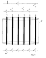
- figure 1 shows a prior art optical fibre ribbon as an example of a data communication cable
- figure 2 shows an optical fibre ribbon according to the present invention, each with incoming and outgoing light signals.
- FIG. 1 it is schematically indicated what the delay time of optical signals in a prior art optical fibre ribbon means.
- an optical fibre ribbon 1 composed of individual optical glass fibres 2-7, which optical glass fibres 2-7 are tightly embedded in a matrix material, for example a UV curable resin material
- a light pulse 8 is applied to each optical fibre 2-7, which light pulse 8 exhibits a number of output pulses 9 at the end of the optical fibre ribbon 1.
- the coating(s) on the outer side of the optical glass fibres 2-7 and 12-17 are not shown in the figures.
- the ribbon shown in figures 1 and 2 comprises six parallel optical glass fibres, it is also possible to use different numbers of optical glass fibres.
- FIG. 1 clearly shows that the light pulses applied at the same point in time each exhibit a different, in time, output signal 9 upon exiting the optical fibre ribbon 1, with the skew being represented as the delay time, or, in other words, the difference in time within which the fastest and the slowest pulse have exited the optical fibre ribbon.
- optical glass fibres 12-17 of the fluorine-doped graded-index multimode type in the optical fibre ribbon 10 As is schematically shown in figure 2 , with the fluorine content of the fluorine-doped graded-index multimode glass fibres in the centre of the light-conducting core being practically zero, it has been found to be possible to reduce the skew to a value ⁇ 0.5 ps/m, which is thus schematically shown in figure 2 in that the light pulses 19 exiting the optical glass fibres 12-17 exhibit practically no difference in delay time, the applied light pulses being indicated at 18.
Landscapes
- Physics & Mathematics (AREA)
- Chemical & Material Sciences (AREA)
- Dispersion Chemistry (AREA)
- General Physics & Mathematics (AREA)
- Optics & Photonics (AREA)
- Optical Communication System (AREA)
- Optical Couplings Of Light Guides (AREA)
Abstract
The present invention relates to a data communication cable comprising a plurality of optical glass fibres, in which optical glass fibres of the fluorine-doped graded-index multimode glass fibre type are used. The present invention further relates to the use of fluorine-doped graded-index multimode optical glass fibres in an optical glass fibre ribbon.
The object of the present invention is to provide a data communication cable in which the maximum difference in signal propagation time between the channels in the data communication cable is reduced to a minimum.
Description
- The present invention relates to a data communication cable comprising a plurality of optical glass fibres, which optical glass fibres are arranged side by side. The present invention further relates to the use of fluorine-doped graded-index multimode optical glass fibres in a data communication cable, as well as to the use of such a data communication cable in a data communication system.
- A special type of data communication cable, viz. an optical fibre ribbon, is known, for example from European patent No.
1 279 983 in the name of the present inventor. A ribbon of optical glass fibres is obtained by using a plurality of optical glass fibres, which are arranged parallel to each other in a matrix material. An optical fibre ribbon is formed by embedding a plurality of optical glass fibres in a common matrix material, each optical fibre in the matrix material being embedded in a single-layer or multilayer coating of a UV curable resin, for example a UV acrylate. The optical fibre ribbon is obtained by arranging the thus coated optical glass fibres side by side in a flat configuration in a matrix material. The optical glass fibres to which the present application relates have been obtained from so-called glass preforms, which preforms are heated in a suitable drawing tower for obtaining the intended glass fibre. - Optical fibre ribbons are used for data communication applications in which a high data speed is used. The effective high data speed is obtained by parallel transmission on a plurality of glass fibres, using a correspondingly lower speed. However, in such a situation a delay time occurs for each optical fibre, which may lead to differences in the signal arrival times between respective fibre channels. This leads to a spreading between the light pulses on the various optical glass fibres, which phenomenon is referred to as "Skew" in practice. Skew is the maximum difference in signal propagation time between the channels in the optical fibre ribbon. Skew is an important factor in determining the maximum speed of synchronous parallel data transmission.
- In practice, skew is for example compensated by using special electronics in the receiver at the end of the parallel transmission channel. The differences in the delay time that occur are attributed to differences in the various optical glass fibres and to differences in the cabling characteristic of each individual fibre, viz. the tension differences between the inner and the outer glass fibres of the optical fibre ribbon. For a fibre manufacturer it is therefore advisable to market glass fibres exhibiting a minimum delay time for each fibre.
- From
US patent No. 5,768,460 there is known an optical fibre ribbon in which the delay time would be minimized by selecting the glass fibres used in the optical fibre ribbon from the same original drawing batch. Said US patent further indicates that a minimized delay time could be realised by using a reinforcing element in the optical fibre ribbon, so that the tension exerted on the optical glass fibres is made uniform. It is furthermore indicated in said US patent that the provision of an external coating comprising an antistatic material would have an advantageous effect on the minimization of the difference in delay time between the optical glass fibres used in the optical fibre ribbon. - Japanese patent application
JP 2002/202446 - From Japanese patent application
JP 2002/207144 - The present inventors have furthermore found that the differences in delay time for each optical fibre may be caused by a number of effects, in which regard the numerical aperture (NA) of the optical fibre, the used wavelength range of the transmission system and the differential mode delay (DMD) may be mentioned.
- The object of the present invention is therefore to provide a data communication cable in which the maximum difference in signal propagation time between the channels in the data communication cable is reduced to a minimum.
- Accordingly, the present invention as referred to in the introduction is characterised in that optical glass fibres of the fluorine-doped graded-index multimode glass fibre type are used in the data communication cable.
- Differences in the NA of the optical glass fibre are mainly caused by doping differences in the centre of the core of an optical glass fibre. The graded-index refractive index profiles in optical glass fibres are obtained by adding one or more dopants to the core of the optical glass fibre and by having the concentration of said dopants vary as a function of the radius. By using fluorine as a dopant it becomes possible to manufacture a graded-index optical glass fibre in which the concentration of dopants in the centre of the core is practically zero. Such fibres exhibit a very small NA tolerance. The centre of the core of such glass fibres can be said to consist of practically "pure" quartz glass.
- Using multimode glass fibres of this type, the present inventors have found that the NA tolerances no longer adversely affect the delay time of the lower-order mode groups, because said mode groups propagate mainly in the centre of the optical fibre core. Thus it is possible to develop a data communication cable and use it in a data communication system in which the maximum difference in signal propagation time between the channels in the data communication cable is reduced to a minimum.
- The present invention further relates to the use of optical glass fibres in a data communication system, of which glass fibres the fluorine content of the fluorine-doped graded-index multimode glass fibres in the centre of the light-conducting core is practically zero. In such a data communication system, the refractive index profile of the core of the optical fibre is constructed so that the fluorine content in the centre of the core is practically zero, said fluorine content preferably amounting to zero.
- The present invention further relates to the use of such fluorine-doped graded-index multimode glass fibres in a data communication cable, in which the fluorine content of the fluorine-doped graded-index multimode glass fibres in the centre of the core is practically zero.
- Using fluorine-doped graded-index multimode glass fibres according to the present invention, the differences in delay time of optical signals in such an optical fibre ribbon can be reduced to a value < 0.5 ps/m. It is in particular desirable to have parallel transmission take place through two or more optical glass fibres arranged side by side, viz. embedded in a polymeric material, in particular an optical fibre ribbon.
- The present invention will now be explained in more detail with reference to two figures, of which
figure 1 shows a prior art optical fibre ribbon as an example of a data communication cable, andfigure 2 shows an optical fibre ribbon according to the present invention, each with incoming and outgoing light signals. - In the appended
figure 1 it is schematically indicated what the delay time of optical signals in a prior art optical fibre ribbon means. In an optical fibre ribbon 1 composed of individual optical glass fibres 2-7, which optical glass fibres 2-7 are tightly embedded in a matrix material, for example a UV curable resin material, a light pulse 8 is applied to each optical fibre 2-7, which light pulse 8 exhibits a number of output pulses 9 at the end of the optical fibre ribbon 1. For easy reference, the coating(s) on the outer side of the optical glass fibres 2-7 and 12-17 are not shown in the figures. It should be noted that although the ribbon shown infigures 1 and2 comprises six parallel optical glass fibres, it is also possible to use different numbers of optical glass fibres. Furthermore, embodiments of ribbons are conceivable in which the optical glass fibres are arranged in "stacked" planes, in which planes the optical glass fibres are arranged parallel to each other.Figure 1 clearly shows that the light pulses applied at the same point in time each exhibit a different, in time, output signal 9 upon exiting the optical fibre ribbon 1, with the skew being represented as the delay time, or, in other words, the difference in time within which the fastest and the slowest pulse have exited the optical fibre ribbon. By using the optical glass fibres 12-17 of the fluorine-doped graded-index multimode type in theoptical fibre ribbon 10, as is schematically shown infigure 2 , with the fluorine content of the fluorine-doped graded-index multimode glass fibres in the centre of the light-conducting core being practically zero, it has been found to be possible to reduce the skew to a value < 0.5 ps/m, which is thus schematically shown infigure 2 in that thelight pulses 19 exiting the optical glass fibres 12-17 exhibit practically no difference in delay time, the applied light pulses being indicated at 18.
Claims (12)
- A data communication cable comprising a plurality of optical glass fibres, which optical glass fibres are arranged side by side, characterised in that optical glass fibres of the fluorine-doped graded-index multimode glass fibre type are used in the data communication cable.
- A data communication cable according to claim 1, characterised in that the fluorine content of the fluorine-doped graded-index multimode glass fibres in the centre of the light-conducting core is practically zero.
- A data communication cable according to one or both of claims 1 or 2, characterised in that the optical glass fibres are arranged side by side, being tightly embedded in a matrix material.
- A data communication cable according to one or more of the preceeding claims, characterised in that the centre of the core of the glass fibres consists of pure quartz glass.
- Use of fluorine-doped graded-index multimode optical glass fibres in a data communication cable.
- Use of fluorine-doped graded-index multimode optical glass fibres having a fluorine content of practically zero in the centre of the light-conducting core in a data communication cable.
- Use of fluorine-doped graded-index multimode optical glass fibres in a data communication system in which parallel transmission through two or more optical glass fibres arranged side by side takes place.
- Use of fluorine-doped graded-index multimode optical glass fibres in which the fluorine content in the centre of the light-conducting core is practically zero in which parallel transmission through two or more optical glass fibres arranged side by side takes place.
- Use of fluorine-doped graded-index multimode optical glass fibres in a data communication cable wherein the centre of the core of these glass fibers consists of pure quartz glass.
- Use of fluorine-doped graded-index multimode optical glass fibres in a data communication cable according to one or more of claims 5-9 for reducing the differences in delay time of optical signals to a value < 0.5 ps/m.
- Use of a data communication cable according to one or more of claims 1-4 in a data communication system in which parallel transmission through two or more optical glass fibres arranged side by side takes place.
- Use according to claim 11 for reducing the differences in delay time of optical signals to a value < 0.5 ps/m.
Applications Claiming Priority (1)
| Application Number | Priority Date | Filing Date | Title |
|---|---|---|---|
| NL1035403A NL1035403C2 (en) | 2008-05-08 | 2008-05-08 | Data communication cable. |
Publications (1)
| Publication Number | Publication Date |
|---|---|
| EP2116876A1 true EP2116876A1 (en) | 2009-11-11 |
Family
ID=39730583
Family Applications (1)
| Application Number | Title | Priority Date | Filing Date |
|---|---|---|---|
| EP09005919A Withdrawn EP2116876A1 (en) | 2008-05-08 | 2009-04-29 | Optical data communication cable |
Country Status (4)
| Country | Link |
|---|---|
| US (1) | US20090279834A1 (en) |
| EP (1) | EP2116876A1 (en) |
| CN (1) | CN101576640A (en) |
| NL (1) | NL1035403C2 (en) |
Families Citing this family (1)
| Publication number | Priority date | Publication date | Assignee | Title |
|---|---|---|---|---|
| MY152327A (en) * | 2007-11-30 | 2014-09-15 | Teijin Aramid Bv | Flexible continuous tape from multifilament yarn and method for making these |
Citations (11)
| Publication number | Priority date | Publication date | Assignee | Title |
|---|---|---|---|---|
| US4560247A (en) * | 1983-07-01 | 1985-12-24 | Quartz Et Silice | Large bandwidth optical fibers |
| US5768460A (en) | 1995-10-03 | 1998-06-16 | Siecor Corporation | Low skew optical fiber ribbons |
| EP1120382A2 (en) * | 2000-01-28 | 2001-08-01 | Shin-Etsu Chemical Co., Ltd. | Glass preform and optical fibre and method of manufacturing the preform |
| JP2002202446A (en) | 2000-12-28 | 2002-07-19 | Fujikura Ltd | Method for manufacturing low skew optical fiber tape and low skew optical fiber tape |
| JP2002207144A (en) | 2001-01-05 | 2002-07-26 | Fujikura Ltd | Multimode optical fiber ribbon |
| EP1279983A1 (en) | 2001-07-26 | 2003-01-29 | Alcatel | Optical fibre ribbon |
| EP1503230A1 (en) * | 2003-07-28 | 2005-02-02 | Draka Fibre Technology B.V. | Multimode optical fibre, optical communication system using same and method for manufacturing such a fibre |
| US20050053351A1 (en) * | 2003-09-09 | 2005-03-10 | Fujikura Ltd. | Graded-index multimode fiber and manufacturing method therefor |
| US20050062181A1 (en) * | 2003-02-10 | 2005-03-24 | Walker James K. | Method and apparatus for manufacturing plastic optical transmission medium |
| US7315677B1 (en) * | 2006-09-14 | 2008-01-01 | Corning Incorporated | Dual dopant dual alpha multimode optical fiber |
| EP1895337A1 (en) * | 2006-08-28 | 2008-03-05 | Furukawa Electric North America Inc. | Multi-wavelength, multimode optical fibers |
Family Cites Families (8)
| Publication number | Priority date | Publication date | Assignee | Title |
|---|---|---|---|---|
| JPS60215550A (en) * | 1984-04-12 | 1985-10-28 | Sumitomo Electric Ind Ltd | Quartz based glass fiber for optical transmission containing fluorine and p2o5 |
| DE4001781C1 (en) * | 1990-01-23 | 1991-02-21 | Schott Glaswerke, 6500 Mainz, De | |
| US5729645A (en) * | 1996-08-13 | 1998-03-17 | The Trustees Of The University Of Pennsylvania | Graded index optical fibers |
| US6434309B1 (en) * | 1999-02-22 | 2002-08-13 | Corning Incorporated | Laser optimized multimode fiber and method for use with laser and LED sources and system employing same |
| US20020083739A1 (en) * | 2000-12-29 | 2002-07-04 | Pandelisev Kiril A. | Hot substrate deposition fiber optic preforms and preform components process and apparatus |
| US6731844B2 (en) * | 2001-06-21 | 2004-05-04 | Corning Cable Systems Llc | Identification of optical ribbons |
| DE602004016706D1 (en) * | 2003-07-18 | 2008-11-06 | Fujikura Ltd | Multimode gradient index fiber and manufacturing method |
| EP1952186A4 (en) * | 2005-11-23 | 2010-08-04 | Corning Inc | Low attenuation non-zero dispersion shifted optical fiber |
-
2008
- 2008-05-08 NL NL1035403A patent/NL1035403C2/en not_active IP Right Cessation
-
2009
- 2009-04-29 EP EP09005919A patent/EP2116876A1/en not_active Withdrawn
- 2009-05-06 US US12/436,228 patent/US20090279834A1/en not_active Abandoned
- 2009-05-08 CN CNA200910138573XA patent/CN101576640A/en active Pending
Patent Citations (11)
| Publication number | Priority date | Publication date | Assignee | Title |
|---|---|---|---|---|
| US4560247A (en) * | 1983-07-01 | 1985-12-24 | Quartz Et Silice | Large bandwidth optical fibers |
| US5768460A (en) | 1995-10-03 | 1998-06-16 | Siecor Corporation | Low skew optical fiber ribbons |
| EP1120382A2 (en) * | 2000-01-28 | 2001-08-01 | Shin-Etsu Chemical Co., Ltd. | Glass preform and optical fibre and method of manufacturing the preform |
| JP2002202446A (en) | 2000-12-28 | 2002-07-19 | Fujikura Ltd | Method for manufacturing low skew optical fiber tape and low skew optical fiber tape |
| JP2002207144A (en) | 2001-01-05 | 2002-07-26 | Fujikura Ltd | Multimode optical fiber ribbon |
| EP1279983A1 (en) | 2001-07-26 | 2003-01-29 | Alcatel | Optical fibre ribbon |
| US20050062181A1 (en) * | 2003-02-10 | 2005-03-24 | Walker James K. | Method and apparatus for manufacturing plastic optical transmission medium |
| EP1503230A1 (en) * | 2003-07-28 | 2005-02-02 | Draka Fibre Technology B.V. | Multimode optical fibre, optical communication system using same and method for manufacturing such a fibre |
| US20050053351A1 (en) * | 2003-09-09 | 2005-03-10 | Fujikura Ltd. | Graded-index multimode fiber and manufacturing method therefor |
| EP1895337A1 (en) * | 2006-08-28 | 2008-03-05 | Furukawa Electric North America Inc. | Multi-wavelength, multimode optical fibers |
| US7315677B1 (en) * | 2006-09-14 | 2008-01-01 | Corning Incorporated | Dual dopant dual alpha multimode optical fiber |
Also Published As
| Publication number | Publication date |
|---|---|
| US20090279834A1 (en) | 2009-11-12 |
| NL1035403C2 (en) | 2009-11-11 |
| CN101576640A (en) | 2009-11-11 |
Similar Documents
| Publication | Publication Date | Title |
|---|---|---|
| CN104317023B (en) | Connectorized fiber optic cabling | |
| US9360646B2 (en) | Fiber optic ribbon cable | |
| KR100299807B1 (en) | Optical fiber with low dispersion gradient in the erbium amplifier region | |
| EP3754390B1 (en) | Polarization-maintaining multi-core fiber | |
| Sakamoto et al. | Randomly-coupled single-mode 12-core fiber with highest core density | |
| CN112219145A (en) | Multicore Fiber and Multicore Fiber Cables | |
| CN106842419B (en) | A broadband bend-insensitive multimode optical fiber | |
| WO2023234355A1 (en) | Optical fiber ribbon | |
| Sillard et al. | Micro-bend-resistant low-DMGD 6-LP-mode fiber | |
| BR112022006427A2 (en) | MULTI-NUCLEUS FIBER AND EXPANSION SET | |
| EP4231065A1 (en) | Trench assisted multi-core optical fiber with reduced crosstalk | |
| CN101840027A (en) | Spring-type all-fiber precise adjustable optical attenuator | |
| US20090279834A1 (en) | Data communication cable | |
| WO2013051481A1 (en) | Optical fiber | |
| CN108152879A (en) | A kind of controllable multi-core optical fiber of crosstalk | |
| WO2021035191A1 (en) | Coupling loss reduction between optical fibers | |
| WO2016114514A1 (en) | Ribbon optical fiber comprising compact single-mode optical fibers | |
| CN219997338U (en) | Optical fiber and optical fiber communication system | |
| EP2161601B1 (en) | Plastic glass optical fiber | |
| EP4418025A1 (en) | Multicore optical fiber and multicore optical fiber cable | |
| KR20210086206A (en) | Rollable ribbon optical fiber and method for manufacturing the same | |
| US8290365B2 (en) | Simulation of optical characteristics of an optical fiber | |
| KR101788628B1 (en) | Ribbon fiber composed of downsized single-mode fibers | |
| EP4411437A1 (en) | Optical fiber with improved macro-bending and micro-bending performance | |
| Fitz | Technical Considerations for Pairing Very Low Loss Fiber and Cable |
Legal Events
| Date | Code | Title | Description |
|---|---|---|---|
| PUAI | Public reference made under article 153(3) epc to a published international application that has entered the european phase |
Free format text: ORIGINAL CODE: 0009012 |
|
| AK | Designated contracting states |
Kind code of ref document: A1 Designated state(s): AT BE BG CH CY CZ DE DK EE ES FI FR GB GR HR HU IE IS IT LI LT LU LV MC MK MT NL NO PL PT RO SE SI SK TR |
|
| 17P | Request for examination filed |
Effective date: 20100414 |
|
| 17Q | First examination report despatched |
Effective date: 20100607 |
|
| STAA | Information on the status of an ep patent application or granted ep patent |
Free format text: STATUS: THE APPLICATION IS DEEMED TO BE WITHDRAWN |
|
| 18D | Application deemed to be withdrawn |
Effective date: 20171103 |