EP2116788A2 - Method for using outdoor air to cool room devices - Google Patents
Method for using outdoor air to cool room devices Download PDFInfo
- Publication number
- EP2116788A2 EP2116788A2 EP09397511A EP09397511A EP2116788A2 EP 2116788 A2 EP2116788 A2 EP 2116788A2 EP 09397511 A EP09397511 A EP 09397511A EP 09397511 A EP09397511 A EP 09397511A EP 2116788 A2 EP2116788 A2 EP 2116788A2
- Authority
- EP
- European Patent Office
- Prior art keywords
- cooling
- outdoor air
- room devices
- air
- radiator
- Prior art date
- Legal status (The legal status is an assumption and is not a legal conclusion. Google has not performed a legal analysis and makes no representation as to the accuracy of the status listed.)
- Withdrawn
Links
Images
Classifications
-
- F—MECHANICAL ENGINEERING; LIGHTING; HEATING; WEAPONS; BLASTING
- F24—HEATING; RANGES; VENTILATING
- F24F—AIR-CONDITIONING; AIR-HUMIDIFICATION; VENTILATION; USE OF AIR CURRENTS FOR SCREENING
- F24F11/00—Control or safety arrangements
- F24F11/0001—Control or safety arrangements for ventilation
-
- F—MECHANICAL ENGINEERING; LIGHTING; HEATING; WEAPONS; BLASTING
- F24—HEATING; RANGES; VENTILATING
- F24F—AIR-CONDITIONING; AIR-HUMIDIFICATION; VENTILATION; USE OF AIR CURRENTS FOR SCREENING
- F24F5/00—Air-conditioning systems or apparatus not covered by F24F1/00 or F24F3/00, e.g. using solar heat or combined with household units such as an oven or water heater
-
- F—MECHANICAL ENGINEERING; LIGHTING; HEATING; WEAPONS; BLASTING
- F24—HEATING; RANGES; VENTILATING
- F24F—AIR-CONDITIONING; AIR-HUMIDIFICATION; VENTILATION; USE OF AIR CURRENTS FOR SCREENING
- F24F3/00—Air-conditioning systems in which conditioned primary air is supplied from one or more central stations to distributing units in the rooms or spaces where it may receive secondary treatment; Apparatus specially designed for such systems
- F24F3/06—Air-conditioning systems in which conditioned primary air is supplied from one or more central stations to distributing units in the rooms or spaces where it may receive secondary treatment; Apparatus specially designed for such systems characterised by the arrangements for the supply of heat-exchange fluid for the subsequent treatment of primary air in the room units
-
- F—MECHANICAL ENGINEERING; LIGHTING; HEATING; WEAPONS; BLASTING
- F24—HEATING; RANGES; VENTILATING
- F24F—AIR-CONDITIONING; AIR-HUMIDIFICATION; VENTILATION; USE OF AIR CURRENTS FOR SCREENING
- F24F12/00—Use of energy recovery systems in air conditioning, ventilation or screening
-
- F—MECHANICAL ENGINEERING; LIGHTING; HEATING; WEAPONS; BLASTING
- F24—HEATING; RANGES; VENTILATING
- F24F—AIR-CONDITIONING; AIR-HUMIDIFICATION; VENTILATION; USE OF AIR CURRENTS FOR SCREENING
- F24F5/00—Air-conditioning systems or apparatus not covered by F24F1/00 or F24F3/00, e.g. using solar heat or combined with household units such as an oven or water heater
- F24F5/0003—Exclusively-fluid systems
-
- F—MECHANICAL ENGINEERING; LIGHTING; HEATING; WEAPONS; BLASTING
- F24—HEATING; RANGES; VENTILATING
- F24F—AIR-CONDITIONING; AIR-HUMIDIFICATION; VENTILATION; USE OF AIR CURRENTS FOR SCREENING
- F24F5/00—Air-conditioning systems or apparatus not covered by F24F1/00 or F24F3/00, e.g. using solar heat or combined with household units such as an oven or water heater
- F24F5/0007—Air-conditioning systems or apparatus not covered by F24F1/00 or F24F3/00, e.g. using solar heat or combined with household units such as an oven or water heater cooling apparatus specially adapted for use in air-conditioning
- F24F5/001—Compression cycle type
-
- F—MECHANICAL ENGINEERING; LIGHTING; HEATING; WEAPONS; BLASTING
- F25—REFRIGERATION OR COOLING; COMBINED HEATING AND REFRIGERATION SYSTEMS; HEAT PUMP SYSTEMS; MANUFACTURE OR STORAGE OF ICE; LIQUEFACTION SOLIDIFICATION OF GASES
- F25B—REFRIGERATION MACHINES, PLANTS OR SYSTEMS; COMBINED HEATING AND REFRIGERATION SYSTEMS; HEAT PUMP SYSTEMS
- F25B25/00—Machines, plants or systems, using a combination of modes of operation covered by two or more of the groups F25B1/00 - F25B23/00
- F25B25/005—Machines, plants or systems, using a combination of modes of operation covered by two or more of the groups F25B1/00 - F25B23/00 using primary and secondary systems
-
- F—MECHANICAL ENGINEERING; LIGHTING; HEATING; WEAPONS; BLASTING
- F24—HEATING; RANGES; VENTILATING
- F24F—AIR-CONDITIONING; AIR-HUMIDIFICATION; VENTILATION; USE OF AIR CURRENTS FOR SCREENING
- F24F11/00—Control or safety arrangements
- F24F11/0001—Control or safety arrangements for ventilation
- F24F2011/0006—Control or safety arrangements for ventilation using low temperature external supply air to assist cooling
Definitions
- the object of this invention is a method for using outdoor air to cool room devices, e.g. chilled beams.
- a need for cooling in the indoor spaces of buildings arises typically when the temperature of the outdoor air is high.
- the colder temperature of the outdoor air is utilized only in inblowing fan air, i.e. air of a low temperature, e.g. 15 °C, is blown inside.
- This cooling power is not, however, sufficient but instead it is advantageous if the cooling energy contained in outdoor air can be conducted also to the room devices.
- Cooling of the room devices occurring with outdoor air is thus not normally utilized in the cooling of ventilation because it is generally awkward to implement and requires new pipe branches, heat exchangers and pumps to be added to the typical pipe field. Since the cooling plant and the ventilation plant typically come from different suppliers, it is not easy to coordinate these additional structures into a viable apparatus.
- cooling with outdoor air When cooling with outdoor air is used, it is generally implemented by adding apparatuses to the cooling plant, with which the coldness of the outdoor air is transferred to the "main circulation circuit". This means a heat exchanger, its pumps and pipings, etc., must be added to the roof of the building.
- This type of cooling is generally either ON or OFF, i.e. it can only be used when the temperature of the outdoor air is so low that all the cooling can be managed with it.
- the purpose of this invention is to achieve a method for using outdoor air for cooling room devices, to which method the problems described above are not attached.
- the method according to the invention is characterized in that the water returning from the room devices is used in the supply air radiator to heat the supply air, in which case this water cools and is conducted back to the room devices to cool the room spaces. In this way both heating energy and cooling energy are saved.
- One preferred embodiment of the method according to the invention is characterized in that cooling with outdoor air is simultaneous with the cooling occurring by means of the cooling compressors.
- the cooling power with the outdoor air can thus be supplemented with the compressor when the temperature of the outdoor air is not sufficiently low to provide all the necessary cooling.
- Another preferred embodiment of the method according to the invention is characterized in that the operation of the supply air radiator is switched between cooling, heating and cooling with outdoor air according to the situation.
- Cooling of the outdoor air occurs preferably without any external accessories, heat exchangers and fans, which themselves consume energy and reduce the benefit achievable from cooling with outdoor air.
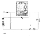
- the main circulation circuit is presented with the reference number 2.
- the outdoor air comes inside via the cooling radiator/heating radiator 3, which is also called the supply air radiator.
- the water returning from all or part of the room devices, e.g. of the chilled beams 4, is conducted to the circulation circuit of the radiator 3.
- This water heats the air passing via the cooling radiator/heating radiator 3 to a suitable temperature for blowing inside.
- the water cools when giving energy to the air.
- the cooled water is conducted back to cooling the room devices. In this way the free cooling energy contained in outdoor air can be transferred to the room devices.
- the cooling compressor 1 can be used at the same time to give additional power.
- the water returning from the room devices divides partly into the branch 6, which conducts for cooling by outdoor air, and partly to the evaporator of the cooling compressor 1, where it is cooled.
- the cooling plant and the ventilation plant are thus made into one integrated entity, in which the cooling radiator of the supply air also functions as a heating radiator of the supply air.
- the cooling radiator of the supply air When cooling of the outdoor air is needed, it functions as a heating radiator.
- the supply air radiator can switch operation between cooling, heating and cooling with outdoor air according to the situation.
- cooling with outdoor air can be used in a much more extensive temperature range than in prior-art solutions because a compressor can be used simultaneously in parallel with it.
Landscapes
- Engineering & Computer Science (AREA)
- Mechanical Engineering (AREA)
- General Engineering & Computer Science (AREA)
- Combustion & Propulsion (AREA)
- Chemical & Material Sciences (AREA)
- Life Sciences & Earth Sciences (AREA)
- Sustainable Development (AREA)
- Thermal Sciences (AREA)
- Physics & Mathematics (AREA)
- Other Air-Conditioning Systems (AREA)
- Air Conditioning Control Device (AREA)
- Devices For Blowing Cold Air, Devices For Blowing Warm Air, And Means For Preventing Water Condensation In Air Conditioning Units (AREA)
- Sorption Type Refrigeration Machines (AREA)
Abstract
Description
- The object of this invention is a method for using outdoor air to cool room devices, e.g. chilled beams.
- A need for cooling in the indoor spaces of buildings arises typically when the temperature of the outdoor air is high. The internal loads of room spaces, such as lighting and computers, create a need for cooling also when the temperature of the outdoor air is low, e.g. below 5 °C. In this case it is possible to use the colder temperature of the outdoor air for cooling the indoor air. Typically the colder temperature of the outdoor air is utilized only in inblowing fan air, i.e. air of a low temperature, e.g. 15 °C, is blown inside. This cooling power is not, however, sufficient but instead it is advantageous if the cooling energy contained in outdoor air can be conducted also to the room devices.
- Cooling of the room devices occurring with outdoor air is thus not normally utilized in the cooling of ventilation because it is generally awkward to implement and requires new pipe branches, heat exchangers and pumps to be added to the typical pipe field. Since the cooling plant and the ventilation plant typically come from different suppliers, it is not easy to coordinate these additional structures into a viable apparatus.
- When cooling with outdoor air is used, it is generally implemented by adding apparatuses to the cooling plant, with which the coldness of the outdoor air is transferred to the "main circulation circuit". This means a heat exchanger, its pumps and pipings, etc., must be added to the roof of the building. This type of cooling is generally either ON or OFF, i.e. it can only be used when the temperature of the outdoor air is so low that all the cooling can be managed with it.
- The purpose of this invention is to achieve a method for using outdoor air for cooling room devices, to which method the problems described above are not attached. The method according to the invention is characterized in that the water returning from the room devices is used in the supply air radiator to heat the supply air, in which case this water cools and is conducted back to the room devices to cool the room spaces. In this way both heating energy and cooling energy are saved.
- One preferred embodiment of the method according to the invention is characterized in that cooling with outdoor air is simultaneous with the cooling occurring by means of the cooling compressors. The cooling power with the outdoor air can thus be supplemented with the compressor when the temperature of the outdoor air is not sufficiently low to provide all the necessary cooling.
- Another preferred embodiment of the method according to the invention is characterized in that the operation of the supply air radiator is switched between cooling, heating and cooling with outdoor air according to the situation.
- Cooling of the outdoor air occurs preferably without any external accessories, heat exchangers and fans, which themselves consume energy and reduce the benefit achievable from cooling with outdoor air.
- In the following, the invention will be described in more detail by the aid of a preferred embodiment with reference to the attached drawing.
- In the diagram presented in the drawing, the main circulation circuit is presented with the
reference number 2. The outdoor air comes inside via the cooling radiator/heating radiator 3, which is also called the supply air radiator. The water returning from all or part of the room devices, e.g. of the chilled beams 4, is conducted to the circulation circuit of the radiator 3. This water heats the air passing via the cooling radiator/heating radiator 3 to a suitable temperature for blowing inside. At the same time the water cools when giving energy to the air. The cooled water is conducted back to cooling the room devices. In this way the free cooling energy contained in outdoor air can be transferred to the room devices. - When sufficient cooling energy is not obtained from the outdoor air, the
cooling compressor 1 can be used at the same time to give additional power. The water returning from the room devices divides partly into thebranch 6, which conducts for cooling by outdoor air, and partly to the evaporator of thecooling compressor 1, where it is cooled. - In the apparatus used in the method according to the invention the cooling plant and the ventilation plant are thus made into one integrated entity, in which the cooling radiator of the supply air also functions as a heating radiator of the supply air. When cooling of the outdoor air is needed, it functions as a heating radiator. What is essential is that the supply air radiator can switch operation between cooling, heating and cooling with outdoor air according to the situation. In the method according to the invention cooling with outdoor air can be used in a much more extensive temperature range than in prior-art solutions because a compressor can be used simultaneously in parallel with it.
- It is obvious to the person skilled in the art that the invention is not limited to the embodiments presented above, but that it can be varied within the scope of the claims presented below. It must be understood that the diagram presented by the drawing and the actuators presented in it are only one possibility for implementing the invention. They can thus be varied according to need.
Claims (3)
- Method for using outdoor air to cool room devices, e.g. chilled beams (4), characterized in that the water returning from the room devices is used in the supply air radiator (3) to heat the supply air, in which case this water cools and is conducted back to the room devices to cool the room spaces.
- Method according to claim 1, characterized in that cooling with outdoor air is simultaneous with the cooling occurring by means of the cooling compressors (1).
- Method according to claim 1 or 2, characterized in that the operation of the supply air radiator (3) is switched between cooling, heating and cooling with outdoor air according to the situation.
Applications Claiming Priority (1)
| Application Number | Priority Date | Filing Date | Title |
|---|---|---|---|
| FI20085412A FI20085412L (en) | 2008-05-06 | 2008-05-06 | A method of using outdoor air to cool room equipment |
Publications (2)
| Publication Number | Publication Date |
|---|---|
| EP2116788A2 true EP2116788A2 (en) | 2009-11-11 |
| EP2116788A3 EP2116788A3 (en) | 2014-08-13 |
Family
ID=39523067
Family Applications (1)
| Application Number | Title | Priority Date | Filing Date |
|---|---|---|---|
| EP09397511.8A Withdrawn EP2116788A3 (en) | 2008-05-06 | 2009-04-02 | Method for using outdoor air to cool room devices |
Country Status (6)
| Country | Link |
|---|---|
| EP (1) | EP2116788A3 (en) |
| KR (1) | KR20090116629A (en) |
| CN (1) | CN101576304B (en) |
| FI (1) | FI20085412L (en) |
| NO (1) | NO20091796L (en) |
| RU (1) | RU2490557C2 (en) |
Cited By (1)
| Publication number | Priority date | Publication date | Assignee | Title |
|---|---|---|---|---|
| EP3757481A4 (en) * | 2018-02-22 | 2021-02-17 | Mitsubishi Electric Corporation | AIR CONDITIONING DEVICE AND AIR HANDLING UNIT |
Families Citing this family (4)
| Publication number | Priority date | Publication date | Assignee | Title |
|---|---|---|---|---|
| RU2583771C2 (en) | 2010-01-24 | 2016-05-10 | Ой Халтон Груп Лтд. | Devices, systems and processes involving cooling beams |
| CN101839527B (en) * | 2010-05-24 | 2012-07-18 | 广东格兰仕集团有限公司 | Unitary air conditioner and operation method thereof |
| KR20140146109A (en) | 2012-03-16 | 2014-12-24 | 오와이 할튼 그룹 엘티디. | Chilled beam with multiple modes |
| CN106091287A (en) * | 2016-06-29 | 2016-11-09 | 马耀东 | A kind of indoor air temperature adjusting means utilizing outside air temperature to change |
Family Cites Families (11)
| Publication number | Priority date | Publication date | Assignee | Title |
|---|---|---|---|---|
| US3252507A (en) * | 1963-06-17 | 1966-05-24 | Patrick R Conroy | Multi-unit air-conditioning systems |
| US3305001A (en) * | 1964-10-26 | 1967-02-21 | Itt | Plural zone heating and cooling system |
| US4446703A (en) * | 1982-05-25 | 1984-05-08 | Gilbertson Thomas A | Air conditioning system and method |
| FI95505C (en) * | 1992-12-08 | 1996-02-12 | Flaekt Oy | Method and apparatus for air conditioning and heating of room spaces |
| US5873256A (en) * | 1994-07-07 | 1999-02-23 | Denniston; James G. T. | Desiccant based humidification/dehumidification system |
| FI100132B (en) * | 1995-03-03 | 1997-09-30 | Abb Installaatiot Oy | Device in an air conditioner |
| SE520099C2 (en) * | 2000-04-14 | 2003-05-27 | Emerson Energy Systems Ab | Device for cooling heat generating units |
| EP1693627A1 (en) * | 2003-12-09 | 2006-08-23 | Earthship K.K. | Air conditioning system |
| CN1563830B (en) * | 2004-04-18 | 2012-06-06 | 大庆富尔达环保节能科技有限责任公司 | Method for utilizing and recovering heat from temp reducing of circulating cooling water |
| CN101915443B (en) * | 2004-11-09 | 2012-08-29 | 松下电器产业株式会社 | Dehumidifier |
| FI20060213L (en) * | 2006-03-03 | 2007-09-04 | Flaekt Woods Ab | Cooling unit |
-
2008
- 2008-05-06 FI FI20085412A patent/FI20085412L/en not_active Application Discontinuation
-
2009
- 2009-04-02 EP EP09397511.8A patent/EP2116788A3/en not_active Withdrawn
- 2009-04-29 KR KR1020090037517A patent/KR20090116629A/en not_active Ceased
- 2009-05-05 RU RU2009117159/12A patent/RU2490557C2/en active
- 2009-05-06 NO NO20091796A patent/NO20091796L/en not_active Application Discontinuation
- 2009-05-06 CN CN200910140507.6A patent/CN101576304B/en not_active Expired - Fee Related
Cited By (2)
| Publication number | Priority date | Publication date | Assignee | Title |
|---|---|---|---|---|
| EP3757481A4 (en) * | 2018-02-22 | 2021-02-17 | Mitsubishi Electric Corporation | AIR CONDITIONING DEVICE AND AIR HANDLING UNIT |
| US12173918B2 (en) | 2018-02-22 | 2024-12-24 | Mitsubishi Electric Corporation | Air-conditioning apparatus and air handling unit |
Also Published As
| Publication number | Publication date |
|---|---|
| FI20085412A7 (en) | 2009-11-07 |
| CN101576304A (en) | 2009-11-11 |
| FI20085412A0 (en) | 2008-05-06 |
| FI20085412L (en) | 2009-11-07 |
| CN101576304B (en) | 2015-09-23 |
| NO20091796L (en) | 2009-11-09 |
| RU2009117159A (en) | 2010-11-10 |
| KR20090116629A (en) | 2009-11-11 |
| RU2490557C2 (en) | 2013-08-20 |
| EP2116788A3 (en) | 2014-08-13 |
Similar Documents
| Publication | Publication Date | Title |
|---|---|---|
| CN111742188B (en) | head pressure control system | |
| WO2009028184A1 (en) | Air conditioning/ventilating system | |
| US10935258B2 (en) | Fan with cooler | |
| CN101576304B (en) | By the method for outdoor air to cool room devices | |
| KR20220169042A (en) | Data center local cooling system with pre-cooling chiller | |
| CN101839536A (en) | Method for air conditioner refrigeration by using fresh air, corresponding refrigeration system and controller | |
| RU2435110C2 (en) | Cooling unit | |
| KR20180010750A (en) | Cooling system for outside air using ahu condensate water and the ship or offshore structure having the same | |
| JP2012026680A (en) | Air conditioning system, and method of controlling the air conditioning system | |
| CN101995064A (en) | Refrigeration crystal air conditioner | |
| KR100812777B1 (en) | Cooling / Heating Separation Heat Pump | |
| JP2588438B2 (en) | Repair method of air conditioning equipment of existing building | |
| JP2011163665A (en) | Method of operating air conditioning system | |
| JP6490095B2 (en) | Air conditioning system | |
| ES2400453T3 (en) | Refrigerator equipment | |
| CN105674433A (en) | Frequency converter air-conditioning system for high-temperature environment | |
| US10077913B2 (en) | Energy transfer system (ETS) | |
| CN101576299A (en) | Method for cooling supply air | |
| JP2007132659A (en) | Heat source system for applying high-temperature cold water | |
| JP2016057040A (en) | Radiant air conditioner | |
| JP2002286309A (en) | Refrigerator | |
| JP6974553B2 (en) | Air conditioner and air conditioning system for air supply / exhaust path | |
| JP4617693B2 (en) | Clean room air conditioning system | |
| CN103256669A (en) | Cooling device | |
| JP4779480B2 (en) | Heat source system for high temperature cold water application |
Legal Events
| Date | Code | Title | Description |
|---|---|---|---|
| PUAI | Public reference made under article 153(3) epc to a published international application that has entered the european phase |
Free format text: ORIGINAL CODE: 0009012 |
|
| AK | Designated contracting states |
Kind code of ref document: A2 Designated state(s): AT BE BG CH CY CZ DE DK EE ES FI FR GB GR HR HU IE IS IT LI LT LU LV MC MK MT NL NO PL PT RO SE SI SK TR |
|
| PUAL | Search report despatched |
Free format text: ORIGINAL CODE: 0009013 |
|
| AK | Designated contracting states |
Kind code of ref document: A3 Designated state(s): AT BE BG CH CY CZ DE DK EE ES FI FR GB GR HR HU IE IS IT LI LT LU LV MC MK MT NL NO PL PT RO SE SI SK TR |
|
| RIC1 | Information provided on ipc code assigned before grant |
Ipc: F24F 5/00 20060101ALI20140709BHEP Ipc: F24F 3/06 20060101ALI20140709BHEP Ipc: H05K 7/20 20060101ALI20140709BHEP Ipc: F25B 25/00 20060101ALI20140709BHEP Ipc: F24F 11/00 20060101AFI20140709BHEP |
|
| STAA | Information on the status of an ep patent application or granted ep patent |
Free format text: STATUS: THE APPLICATION IS DEEMED TO BE WITHDRAWN |
|
| 18D | Application deemed to be withdrawn |
Effective date: 20150214 |