EP2116691A2 - Method for repairing a gas turbine engine component - Google Patents
Method for repairing a gas turbine engine component Download PDFInfo
- Publication number
- EP2116691A2 EP2116691A2 EP09250802A EP09250802A EP2116691A2 EP 2116691 A2 EP2116691 A2 EP 2116691A2 EP 09250802 A EP09250802 A EP 09250802A EP 09250802 A EP09250802 A EP 09250802A EP 2116691 A2 EP2116691 A2 EP 2116691A2
- Authority
- EP
- European Patent Office
- Prior art keywords
- stator assembly
- recited
- turbine engine
- gas turbine
- additional material
- Prior art date
- Legal status (The legal status is an assumption and is not a legal conclusion. Google has not performed a legal analysis and makes no representation as to the accuracy of the status listed.)
- Granted
Links
Images


Classifications
-
- F—MECHANICAL ENGINEERING; LIGHTING; HEATING; WEAPONS; BLASTING
- F01—MACHINES OR ENGINES IN GENERAL; ENGINE PLANTS IN GENERAL; STEAM ENGINES
- F01D—NON-POSITIVE DISPLACEMENT MACHINES OR ENGINES, e.g. STEAM TURBINES
- F01D5/00—Blades; Blade-carrying members; Heating, heat-insulating, cooling or antivibration means on the blades or the members
- F01D5/005—Repairing methods or devices
-
- B—PERFORMING OPERATIONS; TRANSPORTING
- B23—MACHINE TOOLS; METAL-WORKING NOT OTHERWISE PROVIDED FOR
- B23K—SOLDERING OR UNSOLDERING; WELDING; CLADDING OR PLATING BY SOLDERING OR WELDING; CUTTING BY APPLYING HEAT LOCALLY, e.g. FLAME CUTTING; WORKING BY LASER BEAM
- B23K9/00—Arc welding or cutting
- B23K9/04—Welding for other purposes than joining, e.g. built-up welding
- B23K9/044—Built-up welding on three-dimensional surfaces
-
- B—PERFORMING OPERATIONS; TRANSPORTING
- B23—MACHINE TOOLS; METAL-WORKING NOT OTHERWISE PROVIDED FOR
- B23K—SOLDERING OR UNSOLDERING; WELDING; CLADDING OR PLATING BY SOLDERING OR WELDING; CUTTING BY APPLYING HEAT LOCALLY, e.g. FLAME CUTTING; WORKING BY LASER BEAM
- B23K9/00—Arc welding or cutting
- B23K9/16—Arc welding or cutting making use of shielding gas
- B23K9/173—Arc welding or cutting making use of shielding gas and of a consumable electrode
-
- B—PERFORMING OPERATIONS; TRANSPORTING
- B23—MACHINE TOOLS; METAL-WORKING NOT OTHERWISE PROVIDED FOR
- B23P—METAL-WORKING NOT OTHERWISE PROVIDED FOR; COMBINED OPERATIONS; UNIVERSAL MACHINE TOOLS
- B23P6/00—Restoring or reconditioning objects
- B23P6/002—Repairing turbine components, e.g. moving or stationary blades, rotors
- B23P6/007—Repairing turbine components, e.g. moving or stationary blades, rotors using only additive methods, e.g. build-up welding
-
- B—PERFORMING OPERATIONS; TRANSPORTING
- B23—MACHINE TOOLS; METAL-WORKING NOT OTHERWISE PROVIDED FOR
- B23K—SOLDERING OR UNSOLDERING; WELDING; CLADDING OR PLATING BY SOLDERING OR WELDING; CUTTING BY APPLYING HEAT LOCALLY, e.g. FLAME CUTTING; WORKING BY LASER BEAM
- B23K2101/00—Articles made by soldering, welding or cutting
- B23K2101/001—Turbines
-
- F—MECHANICAL ENGINEERING; LIGHTING; HEATING; WEAPONS; BLASTING
- F05—INDEXING SCHEMES RELATING TO ENGINES OR PUMPS IN VARIOUS SUBCLASSES OF CLASSES F01-F04
- F05D—INDEXING SCHEME FOR ASPECTS RELATING TO NON-POSITIVE-DISPLACEMENT MACHINES OR ENGINES, GAS-TURBINES OR JET-PROPULSION PLANTS
- F05D2230/00—Manufacture
- F05D2230/20—Manufacture essentially without removing material
- F05D2230/23—Manufacture essentially without removing material by permanently joining parts together
- F05D2230/232—Manufacture essentially without removing material by permanently joining parts together by welding
-
- Y—GENERAL TAGGING OF NEW TECHNOLOGICAL DEVELOPMENTS; GENERAL TAGGING OF CROSS-SECTIONAL TECHNOLOGIES SPANNING OVER SEVERAL SECTIONS OF THE IPC; TECHNICAL SUBJECTS COVERED BY FORMER USPC CROSS-REFERENCE ART COLLECTIONS [XRACs] AND DIGESTS
- Y10—TECHNICAL SUBJECTS COVERED BY FORMER USPC
- Y10T—TECHNICAL SUBJECTS COVERED BY FORMER US CLASSIFICATION
- Y10T29/00—Metal working
- Y10T29/49—Method of mechanical manufacture
- Y10T29/49316—Impeller making
- Y10T29/49318—Repairing or disassembling
-
- Y—GENERAL TAGGING OF NEW TECHNOLOGICAL DEVELOPMENTS; GENERAL TAGGING OF CROSS-SECTIONAL TECHNOLOGIES SPANNING OVER SEVERAL SECTIONS OF THE IPC; TECHNICAL SUBJECTS COVERED BY FORMER USPC CROSS-REFERENCE ART COLLECTIONS [XRACs] AND DIGESTS
- Y10—TECHNICAL SUBJECTS COVERED BY FORMER USPC
- Y10T—TECHNICAL SUBJECTS COVERED BY FORMER US CLASSIFICATION
- Y10T29/00—Metal working
- Y10T29/49—Method of mechanical manufacture
- Y10T29/49718—Repairing
- Y10T29/49721—Repairing with disassembling
- Y10T29/49723—Repairing with disassembling including reconditioning of part
- Y10T29/49725—Repairing with disassembling including reconditioning of part by shaping
- Y10T29/49726—Removing material
-
- Y—GENERAL TAGGING OF NEW TECHNOLOGICAL DEVELOPMENTS; GENERAL TAGGING OF CROSS-SECTIONAL TECHNOLOGIES SPANNING OVER SEVERAL SECTIONS OF THE IPC; TECHNICAL SUBJECTS COVERED BY FORMER USPC CROSS-REFERENCE ART COLLECTIONS [XRACs] AND DIGESTS
- Y10—TECHNICAL SUBJECTS COVERED BY FORMER USPC
- Y10T—TECHNICAL SUBJECTS COVERED BY FORMER US CLASSIFICATION
- Y10T29/00—Metal working
- Y10T29/49—Method of mechanical manufacture
- Y10T29/49718—Repairing
- Y10T29/49721—Repairing with disassembling
- Y10T29/49723—Repairing with disassembling including reconditioning of part
- Y10T29/49725—Repairing with disassembling including reconditioning of part by shaping
- Y10T29/49726—Removing material
- Y10T29/49728—Removing material and by a metallurgical operation, e.g., welding, diffusion bonding, casting
-
- Y—GENERAL TAGGING OF NEW TECHNOLOGICAL DEVELOPMENTS; GENERAL TAGGING OF CROSS-SECTIONAL TECHNOLOGIES SPANNING OVER SEVERAL SECTIONS OF THE IPC; TECHNICAL SUBJECTS COVERED BY FORMER USPC CROSS-REFERENCE ART COLLECTIONS [XRACs] AND DIGESTS
- Y10—TECHNICAL SUBJECTS COVERED BY FORMER USPC
- Y10T—TECHNICAL SUBJECTS COVERED BY FORMER US CLASSIFICATION
- Y10T29/00—Metal working
- Y10T29/49—Method of mechanical manufacture
- Y10T29/49718—Repairing
- Y10T29/49721—Repairing with disassembling
- Y10T29/4973—Replacing of defective part
Definitions
- This disclosure relates to a method for repairing a worn surface of a gas turbine engine component.
- Gas turbine engines typically include a compressor section, a combustor section and a turbine section. Air is pressurized in the compressor section, and is mixed with fuel and burned in the combustor section to energize and expand the air and accelerate the airflow into the turbine section. The hot combustion gases that exit the combustor section flow downstream through the turbine section, which extracts kinetic energy from the expanding gases and converts the energy into mechanical power to drive the compressor section.
- the compressor section of the gas turbine engine typically includes multiple compression stages to obtain high pressure levels.
- Each compressor stage consists of alternating rows of stator assemblies that include stationary airfoils called stator vanes followed by rotor assemblies including moving airfoils called rotor blades.
- stator vanes direct incoming airflow to the next set of rotor blades.
- portions of the stator assemblies may become worn as a result of rubbing that occurs between the stator assemblies and surrounding components of the gas turbine engine.
- the rubbing may wear and stress portions of the stator assemblies.
- stator assemblies are often repaired instead of replaced.
- the repairs generally involve removing the worn surfaces of the stator assembly, and then restoring them with weld filler or similar material on a surface of the component.
- the material build-up is machined to an appropriate shape to form a restored surface.
- GTA gas tungsten arc
- a method of repairing a stator assembly of a gas turbine engine includes removing a worn surface of the stator assembly to provide a revealed area, and securing additional material to the stator assembly utilizing gas metal arc welding.
- a gas turbine engine component includes a stator assembly having at least one repairable surface.
- the stator includes a repaired section. Additional material is deposited on the at least one repairable surface to fabricate the repaired section using gas metal arc welding.
- FIG. 1 schematically illustrates an example gas turbine engine 10 that is circumferentially disposed about an engine centerline axis A.
- the gas turbine engine 10 includes (in serial flow communication) a fan section 12, a low pressure compressor 14, a high pressure compressor 16, a combustor section 18, a high pressure turbine 20, and a low pressure turbine 22.
- airflow is drawn into the gas turbine engine 10 by the fan section 12, and is pressurized in the low pressure compressor 14 and the high pressure compressor 16.
- Fuel is mixed with the pressurized air and combusted within the combustor section 18.
- the combustion gases are discharged through the high pressure turbine 20 and the low pressure turbine 22, which extract energy from the combustion gases for powering the compressor sections 14, 16 and the fan section 12.
- the low pressure compressor 14 and the high pressure compressor 16 include a plurality of alternating rows of rotor assemblies 24 having blades 26 and stator assemblies 28 including vanes 30. It should be understood that the various features and example illustrations presented herein are not limited to a gas turbine engine of this particular architecture. That is, the present disclosure is applicable to any engine architecture, and for any application.
- Figure 2 illustrates an example gas turbine engine component 15 having at least one worn surface 32.
- the gas turbine engine component 15 is a stator assembly 28 of the high pressure compressor 16.
- the stator assembly 28 includes a plurality of vanes 30 that extend between a radially inward honeycomb 34 and a radially outward flange 36.
- the flange 36 includes an outer diameter surface 38 and a plurality of featherseal slots 40 (one shown in Figure 2 ).
- the worn surfaces 32 may occur at any location of the stator assembly 28, including but not limited to, the flange 36, the outer diameter surface 38 and/or the featherseal slot 40.
- the worn surface 32 includes a crack in the outer diameter surface 38.
- the worn surfaces 32 may be caused by the rubbing, vibration and/or extreme temperatures that occur during gas turbine engine 10 operation.
- the worn surfaces 32 are repairable utilizing a gas metal arc welding operation, as is further discussed below.
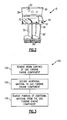
- FIG 3 illustrates an example method 100 for repairing a gas turbine engine component 15.
- the method 100 begins at step block 102 where a worn surface 32 of the gas turbine engine component 15 is removed.
- the worn surface 32 is removed by utilizing a machining operation.
- a person of ordinary skill in the art having the benefit of this disclosure would be able to select an appropriate machining operation for removal of the worn surfaces 32 of the gas turbine engine component 15.
- the worn surface 32 is machined down to remove any damaged portion of the gas turbine engine component 15 (See Figure 4A ).
- step block 104 additional material is secured to the gas turbine engine component 15 utilizing gas metal arc welding.
- the gas metal arc welding includes cold metal transfer. Cold metal transfer is a process developed by the Fronius Corporation and is known. However, gas metal arc welding has not been utilized to repair a worn surface of a gas turbine engine component 15, such as a stator assembly 28 of a high pressure compressor 16, for example.
- the additional material is secured to the gas turbine engine component 15 in an area of the removed worn surface 32.
- a portion of the additional material is removed from the gas turbine engine component 15.
- the portion of the additional material is removed via a machining operation.
- the additional material is removed down to a pre-defined dimension.
- the predefined dimension includes an original dimension of the gas turbine engine component.
- FIGS 4A - 4C describe an example implementation of the method 100.
- an initial step in the repair of the gas turbine engine component 15 includes machining the worn surface 32 down to a predefined dimension D. Machining the worn surface 32 down to the predefined dimension D includes removal of sufficient material to remove any damaged portion of the gas turbine engine component 15, in this example.
- the actual predefined dimension D will vary depending upon design specific parameters including, but not limited to, the degree of damage to the gas turbine engine component.
- additional material 44 is secured to the gas turbine engine component 15 utilizing a gas metal arc welder 46, for example.
- the additional material 44 is secured to the gas turbine engine component with a manually controlled gas metal arc welder 46.
- the additional material 44 is secured using a robotically controlled gas metal arc welder 46.
- the gas metal arc welder 46 can include cold metal transfer.
- the additional material 44 is secured to a revealed area 48 of the gas turbine engine component 15. The revealed area 48 is provided by removal of the worn surface 32, in one example.
- Figure 4C illustrates removal of a portion of the additional material 44 from the gas turbine engine component 15.
- the additional material 44 is removed down to a predefined dimension D2 to provide a repaired section 50 of the gas turbine engine component 15.
- the predefined dimension D2 relates to an original dimension of the gas turbine engine component 15.
- the example gas metal arc welding operation of the present disclosure facilitates a low heat input, high deposition, and spatter free weld process for repairing worn surfaces of a gas turbine engine component.
- the gas metal arc welding operation may be utilized to repair a worn surface of a stator assembly of a gas turbine engine.
Landscapes
- Engineering & Computer Science (AREA)
- Mechanical Engineering (AREA)
- Physics & Mathematics (AREA)
- Plasma & Fusion (AREA)
- General Engineering & Computer Science (AREA)
- Structures Of Non-Positive Displacement Pumps (AREA)
- Butt Welding And Welding Of Specific Article (AREA)
- Arc Welding In General (AREA)
Abstract
Description
- This disclosure relates to a method for repairing a worn surface of a gas turbine engine component.
- Gas turbine engines typically include a compressor section, a combustor section and a turbine section. Air is pressurized in the compressor section, and is mixed with fuel and burned in the combustor section to energize and expand the air and accelerate the airflow into the turbine section. The hot combustion gases that exit the combustor section flow downstream through the turbine section, which extracts kinetic energy from the expanding gases and converts the energy into mechanical power to drive the compressor section.
- The compressor section of the gas turbine engine typically includes multiple compression stages to obtain high pressure levels. Each compressor stage consists of alternating rows of stator assemblies that include stationary airfoils called stator vanes followed by rotor assemblies including moving airfoils called rotor blades. The stator vanes direct incoming airflow to the next set of rotor blades.
- During operation, portions of the stator assemblies may become worn as a result of rubbing that occurs between the stator assemblies and surrounding components of the gas turbine engine. The rubbing may wear and stress portions of the stator assemblies.
- Replacing an entire stator assembly is expensive due to material and machining costs. Accordingly, stator assemblies are often repaired instead of replaced. The repairs generally involve removing the worn surfaces of the stator assembly, and then restoring them with weld filler or similar material on a surface of the component. The material build-up is machined to an appropriate shape to form a restored surface.
- A known gas tungsten arc (GTA) welding process is generally used to repair worn surfaces of gas turbine engine components. The GTA welding process may be performed manually or robotically to deposit weld material on a worn area of the component. However, GTA welding is a relatively slow build-up process that, because of the inherent heat input, can cause unacceptable component distortion. These aspects have prompted the aerospace industry to seek faster and less heat intensive welding processes.
- A method of repairing a stator assembly of a gas turbine engine includes removing a worn surface of the stator assembly to provide a revealed area, and securing additional material to the stator assembly utilizing gas metal arc welding.
- A gas turbine engine component includes a stator assembly having at least one repairable surface. The stator includes a repaired section. Additional material is deposited on the at least one repairable surface to fabricate the repaired section using gas metal arc welding.
- The various features of the example disclosure can be best understood from the following detailed description. The drawings that accompany the detailed description can be briefly described as follows.
-
-
Figure 1 is a schematic view of an example gas turbine engine; -
Figure 2 illustrates a gas turbine engine component including a worn surface; -
Figure 3 illustrates an example method for repairing the gas turbine engine component illustrated inFigure 2 ; -
Figure 4A shows an initial step in an example repair process; -
Figure 4B shows a subsequent step of the repair process; and -
Figure 4C illustrates yet another step in the repair process. -
Figure 1 schematically illustrates an examplegas turbine engine 10 that is circumferentially disposed about an engine centerline axis A. Thegas turbine engine 10 includes (in serial flow communication) afan section 12, alow pressure compressor 14, ahigh pressure compressor 16, acombustor section 18, a high pressure turbine 20, and alow pressure turbine 22. During operation, airflow is drawn into thegas turbine engine 10 by thefan section 12, and is pressurized in thelow pressure compressor 14 and thehigh pressure compressor 16. Fuel is mixed with the pressurized air and combusted within thecombustor section 18. The combustion gases are discharged through the high pressure turbine 20 and thelow pressure turbine 22, which extract energy from the combustion gases for powering thecompressor sections fan section 12. - The
low pressure compressor 14 and thehigh pressure compressor 16 include a plurality of alternating rows ofrotor assemblies 24 havingblades 26 andstator assemblies 28 includingvanes 30. It should be understood that the various features and example illustrations presented herein are not limited to a gas turbine engine of this particular architecture. That is, the present disclosure is applicable to any engine architecture, and for any application. -
Figure 2 illustrates an example gasturbine engine component 15 having at least oneworn surface 32. In this example, the gasturbine engine component 15 is astator assembly 28 of thehigh pressure compressor 16. Thestator assembly 28 includes a plurality ofvanes 30 that extend between a radiallyinward honeycomb 34 and a radiallyoutward flange 36. Theflange 36 includes anouter diameter surface 38 and a plurality of featherseal slots 40 (one shown inFigure 2 ). - The
worn surfaces 32 may occur at any location of thestator assembly 28, including but not limited to, theflange 36, theouter diameter surface 38 and/or thefeatherseal slot 40. In one example, theworn surface 32 includes a crack in theouter diameter surface 38. Theworn surfaces 32 may be caused by the rubbing, vibration and/or extreme temperatures that occur duringgas turbine engine 10 operation. Theworn surfaces 32 are repairable utilizing a gas metal arc welding operation, as is further discussed below. Although the disclosed examples are illustrated with respect to astator assembly 28 of ahigh pressure compressor 16, it should be understood that the disclosed examples may be applied to any gas turbine engine component. -
Figure 3 , with continued reference toFigures 1 and2 , illustrates anexample method 100 for repairing a gasturbine engine component 15. Themethod 100 begins atstep block 102 where aworn surface 32 of the gasturbine engine component 15 is removed. In one example, theworn surface 32 is removed by utilizing a machining operation. A person of ordinary skill in the art having the benefit of this disclosure would be able to select an appropriate machining operation for removal of theworn surfaces 32 of the gasturbine engine component 15. In one example, theworn surface 32 is machined down to remove any damaged portion of the gas turbine engine component 15 (SeeFigure 4A ). - Next, at
step block 104, additional material is secured to the gasturbine engine component 15 utilizing gas metal arc welding. In one example, the gas metal arc welding includes cold metal transfer. Cold metal transfer is a process developed by the Fronius Corporation and is known. However, gas metal arc welding has not been utilized to repair a worn surface of a gasturbine engine component 15, such as astator assembly 28 of ahigh pressure compressor 16, for example. The additional material is secured to the gasturbine engine component 15 in an area of the removedworn surface 32. - At
step block 106, a portion of the additional material is removed from the gasturbine engine component 15. In one example, the portion of the additional material is removed via a machining operation. The additional material is removed down to a pre-defined dimension. In one example, the predefined dimension includes an original dimension of the gas turbine engine component. -
Figures 4A - 4C describe an example implementation of themethod 100. Referring toFigure 4A , an initial step in the repair of the gasturbine engine component 15 includes machining theworn surface 32 down to a predefined dimension D. Machining theworn surface 32 down to the predefined dimension D includes removal of sufficient material to remove any damaged portion of the gasturbine engine component 15, in this example. The actual predefined dimension D will vary depending upon design specific parameters including, but not limited to, the degree of damage to the gas turbine engine component. - As shown in
Figure 4B ,additional material 44 is secured to the gasturbine engine component 15 utilizing a gasmetal arc welder 46, for example. In one example, theadditional material 44 is secured to the gas turbine engine component with a manually controlled gasmetal arc welder 46. In another example, theadditional material 44 is secured using a robotically controlled gasmetal arc welder 46. As described above, the gasmetal arc welder 46 can include cold metal transfer. Theadditional material 44 is secured to a revealedarea 48 of the gasturbine engine component 15. The revealedarea 48 is provided by removal of theworn surface 32, in one example. -
Figure 4C illustrates removal of a portion of theadditional material 44 from the gasturbine engine component 15. Theadditional material 44 is removed down to a predefined dimension D2 to provide a repairedsection 50 of the gasturbine engine component 15. In one example, the predefined dimension D2 relates to an original dimension of the gasturbine engine component 15. - The example gas metal arc welding operation of the present disclosure facilitates a low heat input, high deposition, and spatter free weld process for repairing worn surfaces of a gas turbine engine component. For example, the gas metal arc welding operation may be utilized to repair a worn surface of a stator assembly of a gas turbine engine.
- The foregoing description shall be interpreted as illustrative and not in any limiting sense. A worker of ordinary skill in the art would understand that certain modifications would come within the scope of this disclosure. For these reasons, the following claims should be studied to determine the true scope and content of this disclosure.
Claims (15)
- A method for repairing a stator assembly (28) of a gas turbine engine, comprising the steps of:a) removing a worn surface (32) of the stator assembly to provide a revealed area; andb) securing additional material (44) to the stator assembly utilizing gas metal arc welding.
- The method as recited in claim 1, wherein said step a) includes the step of:machining the worn surface (32) down to a predefined dimension (D).
- The method as recited in claim 2, wherein the step of machining the worn surface (32) down to the predefined dimension (D) includes removal of sufficient material to remove any damaged portion of the stator assembly.
- The method as recited in any preceding claim, wherein the gas metal arc welding includes cold metal transfer.
- The method as recited in any preceding claim, wherein said step b) includes the step of:securing the additional material (44) to the revealed area of the stator assembly.
- The method as recited in any preceding claim, comprising the step of:c) removing a portion of the additional material (44).
- The method as recited in claim 6, wherein said step c) includes the step of:machining the additional material (44) down to a predefined dimension.
- The method as recited in any preceding claim, wherein the stator assembly (28) is a component of a high pressure compressor of the gas turbine engine.
- The method as recited in any preceding claim, wherein the additional material (44) is applied manually to the stator assembly.
- The method as recited in any of claims 1 to 8, wherein the additional material (44) is applied robotically to the stator assembly.
- A gas turbine engine component (15), comprising:a stator assembly (28) having at least one repairable surface (32); anda repaired section of said stator assembly, wherein additional material (44) is deposited on said at least one repairable surface to fabricate said repaired section using gas metal arc welding.
- The component as recited in claim 11, wherein said gas turbine engine component (15) is a high pressure compressor stator assembly.
- The invention as recited in any preceding claim, wherein said surface is a flange (36) of said stator assembly (28).
- The invention as recited in any of claims 1 to 12, wherein said surface is a featherseal slot (40) of said stator assembly (28).
- The invention as recited in any of claims 1 to 12, wherein said surface includes a crack in said stator assembly (28).
Applications Claiming Priority (1)
| Application Number | Priority Date | Filing Date | Title |
|---|---|---|---|
| US12/114,836 US8510926B2 (en) | 2008-05-05 | 2008-05-05 | Method for repairing a gas turbine engine component |
Publications (3)
| Publication Number | Publication Date |
|---|---|
| EP2116691A2 true EP2116691A2 (en) | 2009-11-11 |
| EP2116691A3 EP2116691A3 (en) | 2012-07-18 |
| EP2116691B1 EP2116691B1 (en) | 2018-05-02 |
Family
ID=40578200
Family Applications (1)
| Application Number | Title | Priority Date | Filing Date |
|---|---|---|---|
| EP09250802.7A Revoked EP2116691B1 (en) | 2008-05-05 | 2009-03-23 | Method for repairing a stator assembly of a gas turbine engine and gas turbine engine component |
Country Status (2)
| Country | Link |
|---|---|
| US (1) | US8510926B2 (en) |
| EP (1) | EP2116691B1 (en) |
Cited By (8)
| Publication number | Priority date | Publication date | Assignee | Title |
|---|---|---|---|---|
| FR2959434A1 (en) * | 2010-04-30 | 2011-11-04 | Snecma | Aluminum retention casing repairing method for aircraft turbomachine, involves reconstructing flange by reloading metal on flange lower part surface by metal inert gas welding apparatus, and machining metal to obtain flange's final geometry |
| FR2982782A1 (en) * | 2011-11-21 | 2013-05-24 | Snecma | PROCESS FOR THE REPAIR OF METAL TURBOMACHINE PARTS MADE OF NICKEL OR COBALT-BASED SUPERALLIATION USING A MIG PROCESS WITH CURRENT AND PULSED DELIVERY WIRE |
| WO2013049456A3 (en) * | 2011-09-30 | 2013-06-13 | General Electric Company | A method of repairing rotating machine components |
| WO2014068222A1 (en) * | 2012-11-05 | 2014-05-08 | Snecma | Method for resurfacing at least one arm of an intermediate casing of a turbomachine |
| US9021675B2 (en) | 2011-08-15 | 2015-05-05 | United Technologies Corporation | Method for repairing fuel nozzle guides for gas turbine engine combustors using cold metal transfer weld technology |
| EP2564979A3 (en) * | 2011-08-29 | 2017-01-25 | United Technologies Corporation | Bushing to repair circumferential flanged ring |
| CN107100682A (en) * | 2016-02-22 | 2017-08-29 | 通用电气公司 | The system and method that original place for gas-turbine unit shell space is repaired |
| CN110328438A (en) * | 2019-05-23 | 2019-10-15 | 中国人民解放军第五七一九工厂 | A kind of method that cold metal transfer technology repairs aero-engine cast superalloy part |
Families Citing this family (9)
| Publication number | Priority date | Publication date | Assignee | Title |
|---|---|---|---|---|
| US8510926B2 (en) * | 2008-05-05 | 2013-08-20 | United Technologies Corporation | Method for repairing a gas turbine engine component |
| US8910378B2 (en) | 2012-05-01 | 2014-12-16 | United Technologies Corporation | Method for working of combustor float wall panels |
| EP3736073B1 (en) * | 2013-02-28 | 2025-12-10 | RTX Corporation | Method for repairing an aerospace component |
| DE102013214781B3 (en) | 2013-07-29 | 2015-02-26 | MTU Aero Engines AG | Method for repairing a pick-up hook for guide vanes |
| US11047398B2 (en) | 2014-08-05 | 2021-06-29 | Energy Recovery, Inc. | Systems and methods for repairing fluid handling equipment |
| CN104827167B (en) * | 2015-05-19 | 2017-01-18 | 山东能源重型装备制造集团有限责任公司 | Reproducing method for scraper conveyor |
| EP3434864B1 (en) | 2017-07-27 | 2020-12-16 | General Electric Company | A method and system for repairing a turbomachine |
| CN110116257A (en) * | 2019-05-09 | 2019-08-13 | 福尼斯(南京)表面工程技术有限公司 | A kind of welding method being applied to radial bearing shell babbit using CMT |
| CN112548574A (en) * | 2020-12-24 | 2021-03-26 | 山东中际智能装备有限公司 | Stator twists reverse and welded equipment |
Family Cites Families (56)
| Publication number | Priority date | Publication date | Assignee | Title |
|---|---|---|---|---|
| US4159410A (en) * | 1977-06-13 | 1979-06-26 | General Electric Company | Method and apparatus for applying molten filler material |
| US4397471A (en) * | 1981-09-02 | 1983-08-09 | General Electric Company | Rotary pressure seal structure and method for reducing thermal stresses therein |
| US4441012A (en) * | 1981-12-14 | 1984-04-03 | General Electric Company | Method and apparatus for controlling heating power during the application of molten filler material to a workpiece |
| US4549058A (en) | 1983-09-30 | 1985-10-22 | United Technologies Corporation | Feather seal slot for vanes |
| US4657171A (en) * | 1985-06-13 | 1987-04-14 | General Electric Company | Repair of a member having a projection |
| US4878953A (en) * | 1988-01-13 | 1989-11-07 | Metallurgical Industries, Inc. | Method of refurbishing cast gas turbine engine components and refurbished component |
| US4903888A (en) | 1988-05-05 | 1990-02-27 | Westinghouse Electric Corp. | Turbine system having more failure resistant rotors and repair welding of low alloy ferrous turbine components by controlled weld build-up |
| US5180281A (en) | 1990-09-12 | 1993-01-19 | United Technologies Corporation | Case tying means for gas turbine engine |
| GB9021237D0 (en) | 1990-09-29 | 1990-11-14 | Rolls Royce Plc | A method of welding,a method of applying a metallic wear resistant coating to a metallic substrate and a method of sealing a hole in a metallic substrate |
| US5139738A (en) * | 1990-12-18 | 1992-08-18 | General Electric Company | Corrosion resistant filler weld alloys |
| US5812926A (en) * | 1991-09-03 | 1998-09-22 | General Electric Company | Process for hard facing a substrate |
| CN1041642C (en) * | 1994-06-17 | 1999-01-13 | 株式会社日立制作所 | High Toughness 13Cr5Ni Series Stainless Steel and Its Application |
| US5553370A (en) | 1995-02-09 | 1996-09-10 | Pepe; John | Method for repair of steam turbine blades |
| US5645399A (en) | 1995-03-15 | 1997-07-08 | United Technologies Corporation | Gas turbine engine case coated with thermal barrier coating to control axial airfoil clearance |
| US5898994A (en) * | 1996-06-17 | 1999-05-04 | General Electric Company | Method for repairing a nickel base superalloy article |
| US5823739A (en) | 1996-07-03 | 1998-10-20 | United Technologies Corporation | Containment case for a turbine engine |
| US5794338A (en) * | 1997-04-04 | 1998-08-18 | General Electric Company | Method for repairing a turbine engine member damaged tip |
| US5822852A (en) * | 1997-07-14 | 1998-10-20 | General Electric Company | Method for replacing blade tips of directionally solidified and single crystal turbine blades |
| US6219916B1 (en) | 1997-12-19 | 2001-04-24 | United Technologies Corporation | Method for linear friction welding and product made by such method |
| JP3666256B2 (en) | 1998-08-07 | 2005-06-29 | 株式会社日立製作所 | Steam turbine blade manufacturing method |
| US6468367B1 (en) | 1999-12-27 | 2002-10-22 | General Electric Company | Superalloy weld composition and repaired turbine engine component |
| US6332272B1 (en) * | 2000-01-07 | 2001-12-25 | Siemens Westinghouse Power Corporation | Method of repairing a turbine blade |
| US6568077B1 (en) * | 2000-05-11 | 2003-05-27 | General Electric Company | Blisk weld repair |
| US6353198B1 (en) | 2000-06-14 | 2002-03-05 | General Electric Company | Welded stator winding splice joint for rotary electric machines and method of forming the same |
| US6531005B1 (en) | 2000-11-17 | 2003-03-11 | General Electric Co. | Heat treatment of weld repaired gas turbine engine components |
| US6609894B2 (en) | 2001-06-26 | 2003-08-26 | General Electric Company | Airfoils with improved oxidation resistance and manufacture and repair thereof |
| US6520401B1 (en) * | 2001-09-06 | 2003-02-18 | Sermatech International, Inc. | Diffusion bonding of gaps |
| AT413658B (en) | 2001-09-12 | 2006-04-15 | Fronius Int Gmbh | REMOTE REGULATOR AND CONTROL UNIT FOR A WELDING DEVICE |
| US6908288B2 (en) * | 2001-10-31 | 2005-06-21 | General Electric Company | Repair of advanced gas turbine blades |
| US6487491B1 (en) | 2001-11-21 | 2002-11-26 | United Technologies Corporation | System and method of controlling clearance between turbine engine blades and case based on engine components thermal growth model |
| US6755924B2 (en) | 2001-12-20 | 2004-06-29 | General Electric Company | Method of restoration of mechanical properties of a cast nickel-based super alloy for serviced aircraft components |
| AT502175B1 (en) | 2002-04-10 | 2007-02-15 | Fronius Int Gmbh | WELDING AND WELDING PROCESSING WITH NON-DETERGENT ELECTRODE |
| AT502378B1 (en) | 2002-04-11 | 2007-03-15 | Fronius Int Gmbh | PROCESS FOR PARAMETER SELECTION ON WELDING EQUIPMENT |
| AT413665B (en) | 2002-09-06 | 2006-04-15 | Fronius Int Gmbh | PROCESS FOR QUALITY MONITORING OF SPOT WELDING |
| AT412621B (en) | 2002-12-12 | 2005-05-25 | Fronius Int Gmbh | PROTECTIVE CAP FOR A CONTACT TUBE IN A WELDING BURNER AND A WELDING BURNER WITH A PROTECTIVE CAP |
| US6888090B2 (en) | 2003-01-07 | 2005-05-03 | General Electric Company | Electron beam welding method |
| US6884964B2 (en) * | 2003-01-09 | 2005-04-26 | General Electric Company | Method of weld repairing a component and component repaired thereby |
| US7431347B2 (en) | 2003-09-24 | 2008-10-07 | Siderca S.A.I.C. | Hollow sucker rod connection with second torque shoulder |
| EP1677940B1 (en) | 2003-10-23 | 2013-11-27 | Fronius International GmbH | Method for controlling and/or adjusting a welding process and welding device for carrying out a welding process |
| US7222422B2 (en) * | 2004-02-16 | 2007-05-29 | General Electric Company | Method for refurbishing surfaces subjected to high compression contact |
| US6969826B2 (en) * | 2004-04-08 | 2005-11-29 | General Electric Company | Welding process |
| AT413667B (en) | 2004-05-10 | 2006-04-15 | Fronius Int Gmbh | WELDING PROCESS AND LASER HYBRID WELDING BURNER |
| US7244320B2 (en) | 2004-06-01 | 2007-07-17 | United Technologies Corporation | Methods for repairing gas turbine engine components |
| US7363707B2 (en) * | 2004-06-14 | 2008-04-29 | General Electric Company | Braze repair of shroud block seal teeth in a gas turbine engine |
| US7546684B2 (en) * | 2004-07-27 | 2009-06-16 | General Electric Company | Method for repair and replacement of combustor liner panel |
| US7335427B2 (en) * | 2004-12-17 | 2008-02-26 | General Electric Company | Preform and method of repairing nickel-base superalloys and components repaired thereby |
| EP1674382A1 (en) | 2004-12-22 | 2006-06-28 | Prinoth A.G. | Grouser bar for a crawler chain |
| US7587818B2 (en) | 2004-12-23 | 2009-09-15 | General Electric Company | Repair of gas turbine blade tip without recoating the repaired blade tip |
| AT501995B1 (en) | 2005-05-24 | 2009-07-15 | Fronius Int Gmbh | COLD METAL TRANSFER WELDING METHOD AND WELDING SYSTEM |
| US7498543B2 (en) | 2006-03-22 | 2009-03-03 | Gm Global Technology Operations, Inc. | Method for joining or repairing metal surface parts |
| US7854064B2 (en) * | 2006-06-05 | 2010-12-21 | United Technologies Corporation | Enhanced weldability for high strength cast and wrought nickel superalloys |
| US20080053978A1 (en) | 2006-08-29 | 2008-03-06 | Lincoln Global, Inc. | Welder with positional heat control and method of using same |
| US8091228B2 (en) * | 2007-08-21 | 2012-01-10 | United Technologies Corporation | Method repair of turbine blade tip |
| US8925200B2 (en) | 2008-03-27 | 2015-01-06 | United Technologies Corporation | Method for repairing an airfoil |
| US8510926B2 (en) * | 2008-05-05 | 2013-08-20 | United Technologies Corporation | Method for repairing a gas turbine engine component |
| US7789288B1 (en) * | 2009-07-31 | 2010-09-07 | General Electric Company | Brazing process and material for repairing a component |
-
2008
- 2008-05-05 US US12/114,836 patent/US8510926B2/en active Active
-
2009
- 2009-03-23 EP EP09250802.7A patent/EP2116691B1/en not_active Revoked
Cited By (13)
| Publication number | Priority date | Publication date | Assignee | Title |
|---|---|---|---|---|
| FR2959434A1 (en) * | 2010-04-30 | 2011-11-04 | Snecma | Aluminum retention casing repairing method for aircraft turbomachine, involves reconstructing flange by reloading metal on flange lower part surface by metal inert gas welding apparatus, and machining metal to obtain flange's final geometry |
| EP2559513A3 (en) * | 2011-08-15 | 2015-10-14 | United Technologies Corporation | Method for repairing fuel nozzle guides for gas turbine engine combustors using cold metal transfer weld technology |
| US9995487B2 (en) | 2011-08-15 | 2018-06-12 | United Technologies Corporation | Method for repairing fuel nozzle guides for gas turbine engine combustors using cold metal transfer weld technology |
| US9021675B2 (en) | 2011-08-15 | 2015-05-05 | United Technologies Corporation | Method for repairing fuel nozzle guides for gas turbine engine combustors using cold metal transfer weld technology |
| EP2564979A3 (en) * | 2011-08-29 | 2017-01-25 | United Technologies Corporation | Bushing to repair circumferential flanged ring |
| WO2013049456A3 (en) * | 2011-09-30 | 2013-06-13 | General Electric Company | A method of repairing rotating machine components |
| FR2982782A1 (en) * | 2011-11-21 | 2013-05-24 | Snecma | PROCESS FOR THE REPAIR OF METAL TURBOMACHINE PARTS MADE OF NICKEL OR COBALT-BASED SUPERALLIATION USING A MIG PROCESS WITH CURRENT AND PULSED DELIVERY WIRE |
| GB2521580A (en) * | 2012-11-05 | 2015-06-24 | Snecma | Method for resurfacing at least one arm of an intermediate casing of a turbomachine |
| FR2997646A1 (en) * | 2012-11-05 | 2014-05-09 | Snecma | METHOD FOR RECHARGING AT LEAST ONE INTERMEDIATE CASTER ARM FROM A TURBOMACHINE |
| WO2014068222A1 (en) * | 2012-11-05 | 2014-05-08 | Snecma | Method for resurfacing at least one arm of an intermediate casing of a turbomachine |
| GB2521580B (en) * | 2012-11-05 | 2018-09-19 | Snecma | Method for resurfacing at least one arm of an intermediate casing of a turbomachine |
| CN107100682A (en) * | 2016-02-22 | 2017-08-29 | 通用电气公司 | The system and method that original place for gas-turbine unit shell space is repaired |
| CN110328438A (en) * | 2019-05-23 | 2019-10-15 | 中国人民解放军第五七一九工厂 | A kind of method that cold metal transfer technology repairs aero-engine cast superalloy part |
Also Published As
| Publication number | Publication date |
|---|---|
| US20090271984A1 (en) | 2009-11-05 |
| EP2116691A3 (en) | 2012-07-18 |
| EP2116691B1 (en) | 2018-05-02 |
| US8510926B2 (en) | 2013-08-20 |
Similar Documents
| Publication | Publication Date | Title |
|---|---|---|
| US8510926B2 (en) | Method for repairing a gas turbine engine component | |
| US6494677B1 (en) | Turbine nozzle segment and method of repairing same | |
| US7959409B2 (en) | Repaired vane assemblies and methods of repairing vane assemblies | |
| JP4474146B2 (en) | Assembling repair of casting nozzle | |
| US20080216300A1 (en) | Splitter fairing repair | |
| US8257039B2 (en) | Gas turbine engine case with replaced flange and method of repairing the same using cold metal transfer | |
| EP1099508B1 (en) | Turbine nozzle segment and method of repairing same | |
| EP2998060B1 (en) | Method of replacing damaged blade | |
| EP2339117B1 (en) | Consumable collar for linear friction welding of blade replacement for damaged integrally blades rotors | |
| EP2753799B2 (en) | Nutreparatur einer rotordrahtdichtung | |
| EP2339116B1 (en) | Repair of integrally bladed rotors | |
| CA2529337C (en) | Turbine nozzle segment and method of repairing same | |
| CA2623675C (en) | Turbine nozzle segment and repair method | |
| EP2735704A2 (en) | Method for modifying an airfoil shroud and airfoil | |
| EP1564371B1 (en) | Method of repair a foot of a cast stator vane segment | |
| EP3163015A1 (en) | Power nozzle repair with cooling hardware installed |
Legal Events
| Date | Code | Title | Description |
|---|---|---|---|
| PUAI | Public reference made under article 153(3) epc to a published international application that has entered the european phase |
Free format text: ORIGINAL CODE: 0009012 |
|
| AK | Designated contracting states |
Kind code of ref document: A2 Designated state(s): AT BE BG CH CY CZ DE DK EE ES FI FR GB GR HR HU IE IS IT LI LT LU LV MC MK MT NL NO PL PT RO SE SI SK TR |
|
| AX | Request for extension of the european patent |
Extension state: AL BA RS |
|
| PUAL | Search report despatched |
Free format text: ORIGINAL CODE: 0009013 |
|
| AK | Designated contracting states |
Kind code of ref document: A3 Designated state(s): AT BE BG CH CY CZ DE DK EE ES FI FR GB GR HR HU IE IS IT LI LT LU LV MC MK MT NL NO PL PT RO SE SI SK TR |
|
| AX | Request for extension of the european patent |
Extension state: AL BA RS |
|
| RIC1 | Information provided on ipc code assigned before grant |
Ipc: B23K 9/04 20060101ALI20120614BHEP Ipc: F01D 5/00 20060101AFI20120614BHEP |
|
| 17P | Request for examination filed |
Effective date: 20130107 |
|
| AKX | Designation fees paid |
Designated state(s): DE GB |
|
| 17Q | First examination report despatched |
Effective date: 20160908 |
|
| RAP1 | Party data changed (applicant data changed or rights of an application transferred) |
Owner name: UNITED TECHNOLOGIES CORPORATION |
|
| STAA | Information on the status of an ep patent application or granted ep patent |
Free format text: STATUS: EXAMINATION IS IN PROGRESS |
|
| GRAP | Despatch of communication of intention to grant a patent |
Free format text: ORIGINAL CODE: EPIDOSNIGR1 |
|
| STAA | Information on the status of an ep patent application or granted ep patent |
Free format text: STATUS: GRANT OF PATENT IS INTENDED |
|
| INTG | Intention to grant announced |
Effective date: 20171011 |
|
| GRAS | Grant fee paid |
Free format text: ORIGINAL CODE: EPIDOSNIGR3 |
|
| GRAA | (expected) grant |
Free format text: ORIGINAL CODE: 0009210 |
|
| STAA | Information on the status of an ep patent application or granted ep patent |
Free format text: STATUS: THE PATENT HAS BEEN GRANTED |
|
| AK | Designated contracting states |
Kind code of ref document: B1 Designated state(s): DE GB |
|
| REG | Reference to a national code |
Ref country code: GB Ref legal event code: FG4D |
|
| REG | Reference to a national code |
Ref country code: DE Ref legal event code: R096 Ref document number: 602009052071 Country of ref document: DE |
|
| REG | Reference to a national code |
Ref country code: DE Ref legal event code: R026 Ref document number: 602009052071 Country of ref document: DE |
|
| PLBI | Opposition filed |
Free format text: ORIGINAL CODE: 0009260 |
|
| PLAX | Notice of opposition and request to file observation + time limit sent |
Free format text: ORIGINAL CODE: EPIDOSNOBS2 |
|
| 26 | Opposition filed |
Opponent name: SIEMENS AKTIENGESELLSCHAFT Effective date: 20190111 |
|
| PLBB | Reply of patent proprietor to notice(s) of opposition received |
Free format text: ORIGINAL CODE: EPIDOSNOBS3 |
|
| PGFP | Annual fee paid to national office [announced via postgrant information from national office to epo] |
Ref country code: GB Payment date: 20200221 Year of fee payment: 12 Ref country code: DE Payment date: 20200218 Year of fee payment: 12 |
|
| RDAF | Communication despatched that patent is revoked |
Free format text: ORIGINAL CODE: EPIDOSNREV1 |
|
| REG | Reference to a national code |
Ref country code: DE Ref legal event code: R064 Ref document number: 602009052071 Country of ref document: DE Ref country code: DE Ref legal event code: R103 Ref document number: 602009052071 Country of ref document: DE |
|
| RDAG | Patent revoked |
Free format text: ORIGINAL CODE: 0009271 |
|
| STAA | Information on the status of an ep patent application or granted ep patent |
Free format text: STATUS: PATENT REVOKED |
|
| 27W | Patent revoked |
Effective date: 20200807 |
|
| GBPR | Gb: patent revoked under art. 102 of the ep convention designating the uk as contracting state |
Effective date: 20200807 |