EP2116400B1 - Process of controlling the correct connection of at least one power driven user to various power outlets - Google Patents
Process of controlling the correct connection of at least one power driven user to various power outlets Download PDFInfo
- Publication number
- EP2116400B1 EP2116400B1 EP08155729.0A EP08155729A EP2116400B1 EP 2116400 B1 EP2116400 B1 EP 2116400B1 EP 08155729 A EP08155729 A EP 08155729A EP 2116400 B1 EP2116400 B1 EP 2116400B1
- Authority
- EP
- European Patent Office
- Prior art keywords
- user
- power
- outlets
- signal
- processor
- Prior art date
- Legal status (The legal status is an assumption and is not a legal conclusion. Google has not performed a legal analysis and makes no representation as to the accuracy of the status listed.)
- Active
Links
Images

Classifications
-
- A—HUMAN NECESSITIES
- A01—AGRICULTURE; FORESTRY; ANIMAL HUSBANDRY; HUNTING; TRAPPING; FISHING
- A01B—SOIL WORKING IN AGRICULTURE OR FORESTRY; PARTS, DETAILS, OR ACCESSORIES OF AGRICULTURAL MACHINES OR IMPLEMENTS, IN GENERAL
- A01B59/00—Devices specially adapted for connection between animals or tractors and agricultural machines or implements
Definitions
- This invention relates to a process of controlling the correct connection of at least one power driven user to various power outlets and to an arrangement for running this process.
- EP 1 580 043 A1 discloses a combination of a tractor vehicle and a trailed implement, having at least one sensor, which serves to generate a signal indicating the mechanical coupling state of the trailed implement.
- the sensor is provided on the towing device.
- the signal being fed to the electronic control unit and activating an immobilizer of the tractor vehicle and/or of the trailed implement as a function of the signal and of the connection state of at least one connecting line.
- the problem this invention is based on is seen in the risk of a misconnection in case several users can be connected to several power outlets.
- an electronic and programmable computer provides more flexibility and may even be able to change the assignment during operation to apply different power supply characteristics, like pressure, flow rate, timing, etc.
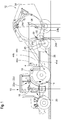
- FIG. 1 shows a tractor 10 and an implement 12 being operated by said tractor 10.
Description
- This invention relates to a process of controlling the correct connection of at least one power driven user to various power outlets and to an arrangement for running this process.
-
DE 10 2005 049 550 A1 discloses a hydraulic system of a work vehicle, like an industrial machine, whereas a tool, like a shovel, can be connected to an arm or the like. Said tool comprises a tool recognition device being capable of producing a recognition signal indicating the type of the tool connected to the work vehicle. As a consequence the hydraulic circuit acts according to the characteristics of the tool. - From
US 2006/0131040 A1 it is known a configurable hydraulic system for an agricultural tractor and implement combination. A controller is used to optimize the number of outlets on selective control valves with respect to the number and kind of connections required by single- or double acting hydraulic actuators, which vary from implement to implement. -
EP 1 580 043 A1 - The problem this invention is based on is seen in the risk of a misconnection in case several users can be connected to several power outlets.
- This problem is solved in an innovative way by means of the teaching of
claims 1 and 4, whereas advantageous features further developing the invention are given in the dependent claims. - By means of this teaching it does not harm, if a remote user is connected to the wrong power outlet for hydraulic, pneumatic or electric power, since the controller assures, that said power is routed to the correct outlet. Insofar the system is self-teaching each time, when users are connected to it. The signal may be transmitted by wire or wireless and may be created by the user itself or by an emitter connected to the power line assigned to the user. The power source may be a single power source, like a pump, with several outlets or it may be several power sources each having one or more outlets. The user may be an electrical, hydraulic or pneumatic motor moving a component on a machine, like a shift lever, a tying system, a bale gate, a tool on a loader, a wrapping table, etc..
- Using an emitter on the power line, its coupler or the like is a fast and simple way to tell the controller, which user is connected to a specific outlet. The emitter may send an electro magnetic or acoustic signal to a receiver close to the outlet. But the emitter could be a bar code as well, which is scanned by a scanner at the outlet. In addition a signal may be emitted by mechanical pins, or the like, which due to their size, combination of several pins, shape, etc. are able to tell a sensor or receiver which user they are assigned to. Preferably the signal is fed via a CAN or ISO bus from an implement, like a baler, mower, planter, loader, etc. to a tractor. Depending on the circumstances the emitter could also be located on the outlet side and the sensor could be on the user side.
- According to the invention one way to create a signal is activating outlets and watching, which of the users is reacting.
- Sensors may be used in a power line, which would recognize flow of power. Sensors may be used as well on the user itself, like potentiometers, reed sensors, load sensors, etc. A process based on test movements of a remote user is according to the invention another way of creating the signal, in order to find out, whether all users are working properly.
- The controller may also have a memory for data about the operation of the respective user, like speed, dampening, pressure, etc. This will not only provide a b/w recognition of the respective user, but also user intelligence. Such additional operation data may also avoid conflicts, in case several users are activated simultaneously.
- In order to run a self-teaching process for supplying power to the correct user an arrangement of coupling parts is provided, in which one is connected to a powered user and at least two are connected to several power outlets of a power source, whereas the part connected to the user contains an emitter for a signal representative for the user, received and used by a controller for the at least two power outlets of the power source. The emitter and the receiver may be of different types, like coded mechanic pins, acoustic or visible signals, electro magnetic or ultrawave signals.
- It is proven technique to use RFID tags, bar codes, wave sensors or the like and that a reader or sensor is provided in the arrangement such, that it can read the RFID tag, etc. once the coupling parts are connected to each other. Such signal providers are simple, cheap and do not require any movement of components by the user. They recognize the kind of the user even before the user would be operated. Such tags, bar codes, etc. could be attached to the exterior of the power line as well as integrated in it, which may provide protection against mechanical stress.
- While in general it would be possible to provide for a mechanical or electrical assignment of the outlets A - D to the
users - Heretoafter two embodiments of the invention are described in more detail and in relation to the drawing. It is shown in:
- Fig. 1
- a tractor and an implement according to a first embodiment of the invention, in which a signal is generated by activating users on the implement, which signal is fed back to a processor on the tractor,
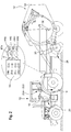
- Fig. 2
- a tractor and an implement according to a second embodiment of the invention, in which a signal is generated by an emitter on a power line, which signal is fed back to the processor on the tractor, and
- Fig. 3
- a diagnostic flow chart.
-
Figure 1 shows atractor 10 and animplement 12 being operated by saidtractor 10. - Instead of said
tractor 10 any other kind of prime mover, like a truck, industrial machine, forestry machine, car, crane, etc. could be used. While theimplement 12 is shown as an agricultural baler it also can be of any kind - hitched to thetractor 10 or attached or coupled to it or at least being operated by it. As example, it could be a front or read end loader, a seeder or planter, a sprayer, a mower, a forage harvester, a cultivator, a trailer, a wrapper, etc. etc. - Said
tractor 10 is provided with apower source 14, preferably supplying hydraulic power, outlets A, B, C, D, apower outlet controller 16 and aprocessor 18. - The
power source 14 as usual contains a pump, valves, lines, sump etc., which are useful to deliver e.g. pressurized oil to the outlets A - D. The outlets A - D usually are sockets into which plugs a, b, c, d at the end of hydraulic, pneumatic orelectric power lines power outlet controller 16. - The
power outlet controller 16 contains spools, electromagnets, etc. as this is known in the art. It has a single inlet from and outlet to thepower source 14 and the outlets A - D, which all are identical and thus allow the insertion of any of the plugs a - d. Thepower outlet controller 16 receives signals from theprocessor 18, such that this specific outlet out of A - D is activated, which is connected to the user, to be operated by a givencontroller 22a - 22d on anoperator station 20 of thetractor 10. Saidcontroller 22a - 22d can be substantially of any type, like a lever, a switch, a touch screen, a key board or the like. A control signal could also be generated automatically by another part of thisprocessor 18 or by another controller on thetractor 10 or on the implement and fed by a BUS system from theimplement 12. - Accordingly, it will depend on the signals received by the
power outlet controller 16 from theprocessor 18 to which outlet A - D power will be directed, rather than by a direct connecting between acontroller operator station 20 and an outlet A - D. - The
processor 18 is located preferably on the operator'sstation 20 and is connected among others to thecontrollers 22a - 22d, to thepower source controller 16 and tosensors figure 1 are located on theimplement 12 and in the embodiment offigure 2 , they are located close to the outlets A - D. Each of thesensors 24a - 24d is assigned to a component on the implement, like a pick-up 26 raised by single actinghydraulic user 28, atwine dispenser 30 moved by a single actinghydraulic user 32, and agate 34 raised and lowered by a double actinghydraulic user 36. Allusers sensors 24a - 24d may be connected to theusers users memory 38 and for the embodiment offigure 1 a routine 40 are provided. It is one of the purposes of theprocessor 18 to receive an input signal from the actuation of one of the controllers 22 and to generate a signal corresponding to the input signal, which is useful to operate therespective user gate 34, theuser 36 needs to extend, which will be accomplished by powering therespective power line 44b through activating the correct outlet A - D. The same would happen if a non shown sensor detects that a bale is produced and tied in the implement 12 and is ready to be ejected, caused by an automatic routine. - In the embodiment of
figure 2 eachpower line 44a - 44d is provided with anemitter user example emitter 42a indicates, that it is connected to the rod end ofuser 36, which will be powered in order to raise thegate 34. While in this embodiment theemitter 42a is an RFID tag, it could also be of any other kind, like a bar code, acoustic or optical waves, mechanical pins with a certain pattern, etc. - The
memory 38 collects information received fromsensors 24a - 24d, which indicate, whichuser memory 38 may also contain information helpful for the operation of the implement 12, like thegate 34 shall not be raised, when thetwine dispenser 30 is activated. Thememory 38 may also contain data about the operation of therespective user motor 32, moving thetwine dispenser 30. - The routine 40 is applied only in the case of the embodiment in
figure 1 and it is the purpose to find out, which of theusers controllers 22a - 22d are activated in series and after activation of onecontroller 22a -22d sensors 24a - 24d are observed for emitting a signal indicating, whichuser users controllers 22a - 22d respective information is stored in thememory 38 and operation of the implement 12 may be started. Once auser - While in this embodiment also the
sensors 24a - 24d are asked for a signal in series, it would also be possible to usesensors 24a - 24d emitting a signal, which is not ON-OFF only, but identifies also theuser sensors 24a - 24d could be checked in parallel.
Claims (5)
- Process of controlling the correct connection of at least one power driven user (28, 32, 36) to various power outlets (A, B, C, D), wherein a signal indicative of the user (28, 32, 36) is emitted to a processor (18) according to which the correct power outlet (A, B, C, D) will be activated, characterized in that the signal is created by activating outlets (A, B, C, D) and watching, which of the users (28, 32, 36) is reacting, or the signal is created by a test movement of the user (28, 32, 36).
- Process according to claim 1, characterized in that this signal is created by an emitter (42a - 42d) attached to a power line (44a, 44b, 44c, 44d) of the user (28, 32, 36) to be connected to the power outlet (A, B, C, D).
- Process according to claim 1, characterized in that operation parameters for the user (28, 32, 36) identified by the signal are taken from a memory (38) in order to control the function of the user (28, 32, 36).
- Arrangement of a tractor (10) and an implement (12) being operated by said tractor (10), said tractor (10) is provided with a power source (14), outlets (A, B, C, D), a power outlet controller (16) and a processor (18), the outlets (A, B, C, D) are sockets into which plugs (a, b, c, d) at the end of power lines (44a, 44b, 44c, 44d) can be inserted, wherein the processor (18) is connected to controllers (22a, 22b, 22c, 22d), to the power source controller (16) and to sensors (24a, 24 b, 24c, 24d), which are located on the implement (12), and each of the sensors (24a - 24d) is assigned to a power driven user (28, 32, 36), the sensors configured for emitting a signal indicative of the user (28, 32, 36) to the processor (18) according to which the correct power outlet (A, B, C, D) is activated, characterized in that the arrangement is configured to create the signal by activating outlets (A, B, C, D) and watching, which of the users (28, 32, 36) is reacting, or by a test movement of the user (28, 32, 36).
- Arrangement according to claim 4, characterized by the processor (18) activating the user (28, 32, 36) by means of the control (22a, 22b, 22c, 22d) assigned to the function of the user (28, 32, 36), irrespective of the chosen connection of the user (28, 32, 36) to either of the power outlets (A, B, C, D).
Priority Applications (4)
| Application Number | Priority Date | Filing Date | Title |
|---|---|---|---|
| PL08155729T PL2116400T3 (en) | 2008-05-06 | 2008-05-06 | Process of controlling the correct connection of at least one power driven user to various power outlets |
| EP08155729.0A EP2116400B1 (en) | 2008-05-06 | 2008-05-06 | Process of controlling the correct connection of at least one power driven user to various power outlets |
| PCT/EP2009/055199 WO2009135793A1 (en) | 2008-05-06 | 2009-04-29 | Process of controlling the correct connection of at least one power driven user to various power outlets |
| US12/991,021 US20110057776A1 (en) | 2008-05-06 | 2009-04-29 | Process Of Controlling The Correct Connection Of At Least One Power Driven User To Various Power Outlets |
Applications Claiming Priority (1)
| Application Number | Priority Date | Filing Date | Title |
|---|---|---|---|
| EP08155729.0A EP2116400B1 (en) | 2008-05-06 | 2008-05-06 | Process of controlling the correct connection of at least one power driven user to various power outlets |
Publications (2)
| Publication Number | Publication Date |
|---|---|
| EP2116400A1 EP2116400A1 (en) | 2009-11-11 |
| EP2116400B1 true EP2116400B1 (en) | 2019-06-19 |
Family
ID=39800679
Family Applications (1)
| Application Number | Title | Priority Date | Filing Date |
|---|---|---|---|
| EP08155729.0A Active EP2116400B1 (en) | 2008-05-06 | 2008-05-06 | Process of controlling the correct connection of at least one power driven user to various power outlets |
Country Status (4)
| Country | Link |
|---|---|
| US (1) | US20110057776A1 (en) |
| EP (1) | EP2116400B1 (en) |
| PL (1) | PL2116400T3 (en) |
| WO (1) | WO2009135793A1 (en) |
Families Citing this family (12)
| Publication number | Priority date | Publication date | Assignee | Title |
|---|---|---|---|---|
| WO2013046237A1 (en) | 2011-09-27 | 2013-04-04 | C.O.B.O. S.P.A | Identification and recognition device for ancillaries of agricultural vehicles |
| DE102016206401A1 (en) * | 2016-04-15 | 2017-10-19 | Deere & Company | Arrangement for determining the plug-in position of a hose coupler on a connecting field |
| EP3379222B1 (en) | 2017-03-22 | 2020-12-30 | Methode Electronics Malta Ltd. | Magnetoelastic based sensor assembly |
| WO2019168565A1 (en) | 2018-02-27 | 2019-09-06 | Methode Electronics,Inc. | Towing systems and methods using magnetic field sensing |
| US11135882B2 (en) | 2018-02-27 | 2021-10-05 | Methode Electronics, Inc. | Towing systems and methods using magnetic field sensing |
| US11221262B2 (en) | 2018-02-27 | 2022-01-11 | Methode Electronics, Inc. | Towing systems and methods using magnetic field sensing |
| US11491832B2 (en) | 2018-02-27 | 2022-11-08 | Methode Electronics, Inc. | Towing systems and methods using magnetic field sensing |
| US11084342B2 (en) | 2018-02-27 | 2021-08-10 | Methode Electronics, Inc. | Towing systems and methods using magnetic field sensing |
| US11071246B2 (en) | 2019-01-29 | 2021-07-27 | Cnh Industrial Canada, Ltd. | System and method for monitoring fluid conduit connections on an agricultural machine |
| US11944028B2 (en) | 2019-08-14 | 2024-04-02 | Cnh Industrial America Llc | Systems and methods for monitoring the installation status of a shank attachment member of an agricultural implement |
| DE102019130688A1 (en) * | 2019-11-14 | 2021-05-20 | Valeo Schalter Und Sensoren Gmbh | Procedure for configuring a trailer detection system |
| WO2023084402A1 (en) * | 2021-11-09 | 2023-05-19 | Mdb Technology Srl | Control method for agricultural or industrial operating machine and agricultural or industrial operating machine |
Family Cites Families (14)
| Publication number | Priority date | Publication date | Assignee | Title |
|---|---|---|---|---|
| SE437861B (en) * | 1983-02-03 | 1985-03-18 | Goran Palmers | DEVICE FOR MEDIUM HYDRAULIC CYLINDER OPERATED MACHINERY WITH ONE OF A DRIVE CELL THROUGH AN ENERGY CUMULATOR DRIVE PUMP |
| US5604681A (en) * | 1994-06-03 | 1997-02-18 | Dover Corporation | Coupler identification systems |
| US6859831B1 (en) * | 1999-10-06 | 2005-02-22 | Sensoria Corporation | Method and apparatus for internetworked wireless integrated network sensor (WINS) nodes |
| US7166937B2 (en) * | 2003-12-15 | 2007-01-23 | Radio Shack Corporation | Power supply, and associated method, exhibiting selectable electrical characteristics |
| US7543655B2 (en) * | 2004-02-10 | 2009-06-09 | Gregg Nathan Buchl | Selective position control system and method |
| DE102004014497A1 (en) * | 2004-03-25 | 2005-11-17 | Deere & Company, Moline | Combination of towing vehicle and trailer device |
| US7114430B2 (en) * | 2004-09-30 | 2006-10-03 | Caterpillar Inc. | Adaptive position determining system for hydraulic cylinder |
| US7441404B2 (en) | 2004-11-30 | 2008-10-28 | Caterpillar Inc. | Configurable hydraulic control system |
| US7434392B2 (en) | 2004-12-16 | 2008-10-14 | Husco International, Inc. | Configurable hydraulic system for agricultural tractor and implement combination |
| FR2887955B1 (en) * | 2005-06-30 | 2008-12-12 | Raymond Et Cie Soc En Commandi | DEVICE FOR CONNECTING TWO TUBULAR ELEMENTS FOR THE TRANSPORT OF FLUIDS |
| DE102006032599A1 (en) * | 2006-07-14 | 2008-02-07 | Deere & Company, Moline | Hydraulic arrangement |
| CA2681103C (en) * | 2007-03-14 | 2015-06-30 | Zonit Structured Solutions, Llc | Smart nema outlets and associated networks |
| US8266456B2 (en) * | 2007-10-15 | 2012-09-11 | Apple Inc. | Supplying remaining available current to port in excess of bus standard limit |
| US8713342B2 (en) * | 2008-04-30 | 2014-04-29 | Raritan Americas, Inc. | System and method for efficient association of a power outlet and device |
-
2008
- 2008-05-06 PL PL08155729T patent/PL2116400T3/en unknown
- 2008-05-06 EP EP08155729.0A patent/EP2116400B1/en active Active
-
2009
- 2009-04-29 US US12/991,021 patent/US20110057776A1/en not_active Abandoned
- 2009-04-29 WO PCT/EP2009/055199 patent/WO2009135793A1/en active Application Filing
Non-Patent Citations (1)
| Title |
|---|
| None * |
Also Published As
| Publication number | Publication date |
|---|---|
| WO2009135793A1 (en) | 2009-11-12 |
| PL2116400T3 (en) | 2019-12-31 |
| EP2116400A1 (en) | 2009-11-11 |
| US20110057776A1 (en) | 2011-03-10 |
Similar Documents
| Publication | Publication Date | Title |
|---|---|---|
| EP2116400B1 (en) | Process of controlling the correct connection of at least one power driven user to various power outlets | |
| US9030040B2 (en) | Electric connection system | |
| US5889671A (en) | Mobile on-board computer system with operation units for machines | |
| US7430465B2 (en) | Open-ended PC host interface for vehicle data recorder | |
| US20140084081A1 (en) | Digital Spray Control System | |
| EP3232759B1 (en) | Fluid connection detector and fluid connection detecting method | |
| DE102005053249A1 (en) | Wireless communication system for work machine components | |
| CN102530728B (en) | There is the engineering machinery of portable operating unit and portable operating unit | |
| US9181965B2 (en) | Hydraulic apparatus control system | |
| US9805234B1 (en) | Arrangement for determining the plugging position of a hose coupling on a connection field | |
| US20090055057A1 (en) | Automated control module for a power machine | |
| US11893892B2 (en) | Utility or upfit vehicle using communication portal | |
| JP2006201851A (en) | Communication system of construction machine | |
| EP1369010B1 (en) | An assembly for performing an agricultural operation, in particular crop processing | |
| JP2005151953A (en) | Electric remote controlling device of farm implement to be attached to tractor | |
| JP6546777B2 (en) | Harness for farm work machine and method of connecting harness for farm work machine | |
| EP3205192A1 (en) | A method of operating an agricultural system having a tractor and an implement, an agricultural system, and a computer program product | |
| EP3163518A1 (en) | Scanned software activation codes in agricultural and construction work equipment systems | |
| JP5775727B2 (en) | Agricultural machine | |
| US20220260093A1 (en) | Connection device | |
| EP3713387A1 (en) | Implement tractor connection application | |
| JP2005151920A (en) | Electric remote controlling device of farm implement to be attached to tractor | |
| EP2741396B1 (en) | Manufacturing device network | |
| JP2005151919A (en) | Electric remote controlling device of farm implement to be attached to tractor | |
| JP6026594B2 (en) | Agricultural machine |
Legal Events
| Date | Code | Title | Description |
|---|---|---|---|
| PUAI | Public reference made under article 153(3) epc to a published international application that has entered the european phase |
Free format text: ORIGINAL CODE: 0009012 |
|
| AK | Designated contracting states |
Kind code of ref document: A1 Designated state(s): AT BE BG CH CY CZ DE DK EE ES FI FR GB GR HR HU IE IS IT LI LT LU LV MC MT NL NO PL PT RO SE SI SK TR |
|
| AX | Request for extension of the european patent |
Extension state: AL BA MK RS |
|
| 17P | Request for examination filed |
Effective date: 20100511 |
|
| AKX | Designation fees paid |
Designated state(s): AT BE BG CH CY CZ DE DK EE ES FI FR GB GR HR HU IE IS IT LI LT LU LV MC MT NL NO PL PT RO SE SI SK TR |
|
| 17Q | First examination report despatched |
Effective date: 20100625 |
|
| STAA | Information on the status of an ep patent application or granted ep patent |
Free format text: STATUS: EXAMINATION IS IN PROGRESS |
|
| REG | Reference to a national code |
Ref country code: DE Ref legal event code: R079 Ref document number: 602008060414 Country of ref document: DE Free format text: PREVIOUS MAIN CLASS: B60D0001620000 Ipc: A01B0059000000 |
|
| GRAP | Despatch of communication of intention to grant a patent |
Free format text: ORIGINAL CODE: EPIDOSNIGR1 |
|
| STAA | Information on the status of an ep patent application or granted ep patent |
Free format text: STATUS: GRANT OF PATENT IS INTENDED |
|
| RIC1 | Information provided on ipc code assigned before grant |
Ipc: A01B 59/00 20060101AFI20180914BHEP |
|
| INTG | Intention to grant announced |
Effective date: 20181009 |
|
| GRAJ | Information related to disapproval of communication of intention to grant by the applicant or resumption of examination proceedings by the epo deleted |
Free format text: ORIGINAL CODE: EPIDOSDIGR1 |
|
| STAA | Information on the status of an ep patent application or granted ep patent |
Free format text: STATUS: EXAMINATION IS IN PROGRESS |
|
| GRAP | Despatch of communication of intention to grant a patent |
Free format text: ORIGINAL CODE: EPIDOSNIGR1 |
|
| STAA | Information on the status of an ep patent application or granted ep patent |
Free format text: STATUS: GRANT OF PATENT IS INTENDED |
|
| INTG | Intention to grant announced |
Effective date: 20190108 |
|
| GRAS | Grant fee paid |
Free format text: ORIGINAL CODE: EPIDOSNIGR3 |
|
| GRAA | (expected) grant |
Free format text: ORIGINAL CODE: 0009210 |
|
| STAA | Information on the status of an ep patent application or granted ep patent |
Free format text: STATUS: THE PATENT HAS BEEN GRANTED |
|
| AK | Designated contracting states |
Kind code of ref document: B1 Designated state(s): AT BE BG CH CY CZ DE DK EE ES FI FR GB GR HR HU IE IS IT LI LT LU LV MC MT NL NO PL PT RO SE SI SK TR |
|
| REG | Reference to a national code |
Ref country code: GB Ref legal event code: FG4D |
|
| REG | Reference to a national code |
Ref country code: CH Ref legal event code: EP |
|
| REG | Reference to a national code |
Ref country code: IE Ref legal event code: FG4D |
|
| REG | Reference to a national code |
Ref country code: DE Ref legal event code: R096 Ref document number: 602008060414 Country of ref document: DE |
|
| REG | Reference to a national code |
Ref country code: AT Ref legal event code: REF Ref document number: 1144296 Country of ref document: AT Kind code of ref document: T Effective date: 20190715 |
|
| REG | Reference to a national code |
Ref country code: NO Ref legal event code: T2 Effective date: 20190619 |
|
| REG | Reference to a national code |
Ref country code: NL Ref legal event code: MP Effective date: 20190619 |
|
| PG25 | Lapsed in a contracting state [announced via postgrant information from national office to epo] |
Ref country code: LT Free format text: LAPSE BECAUSE OF FAILURE TO SUBMIT A TRANSLATION OF THE DESCRIPTION OR TO PAY THE FEE WITHIN THE PRESCRIBED TIME-LIMIT Effective date: 20190619 Ref country code: HR Free format text: LAPSE BECAUSE OF FAILURE TO SUBMIT A TRANSLATION OF THE DESCRIPTION OR TO PAY THE FEE WITHIN THE PRESCRIBED TIME-LIMIT Effective date: 20190619 Ref country code: SE Free format text: LAPSE BECAUSE OF FAILURE TO SUBMIT A TRANSLATION OF THE DESCRIPTION OR TO PAY THE FEE WITHIN THE PRESCRIBED TIME-LIMIT Effective date: 20190619 Ref country code: FI Free format text: LAPSE BECAUSE OF FAILURE TO SUBMIT A TRANSLATION OF THE DESCRIPTION OR TO PAY THE FEE WITHIN THE PRESCRIBED TIME-LIMIT Effective date: 20190619 |
|
| REG | Reference to a national code |
Ref country code: LT Ref legal event code: MG4D |
|
| PG25 | Lapsed in a contracting state [announced via postgrant information from national office to epo] |
Ref country code: LV Free format text: LAPSE BECAUSE OF FAILURE TO SUBMIT A TRANSLATION OF THE DESCRIPTION OR TO PAY THE FEE WITHIN THE PRESCRIBED TIME-LIMIT Effective date: 20190619 Ref country code: BG Free format text: LAPSE BECAUSE OF FAILURE TO SUBMIT A TRANSLATION OF THE DESCRIPTION OR TO PAY THE FEE WITHIN THE PRESCRIBED TIME-LIMIT Effective date: 20190919 Ref country code: GR Free format text: LAPSE BECAUSE OF FAILURE TO SUBMIT A TRANSLATION OF THE DESCRIPTION OR TO PAY THE FEE WITHIN THE PRESCRIBED TIME-LIMIT Effective date: 20190920 |
|
| REG | Reference to a national code |
Ref country code: AT Ref legal event code: MK05 Ref document number: 1144296 Country of ref document: AT Kind code of ref document: T Effective date: 20190619 |
|
| PG25 | Lapsed in a contracting state [announced via postgrant information from national office to epo] |
Ref country code: SK Free format text: LAPSE BECAUSE OF FAILURE TO SUBMIT A TRANSLATION OF THE DESCRIPTION OR TO PAY THE FEE WITHIN THE PRESCRIBED TIME-LIMIT Effective date: 20190619 Ref country code: PT Free format text: LAPSE BECAUSE OF FAILURE TO SUBMIT A TRANSLATION OF THE DESCRIPTION OR TO PAY THE FEE WITHIN THE PRESCRIBED TIME-LIMIT Effective date: 20191021 Ref country code: NL Free format text: LAPSE BECAUSE OF FAILURE TO SUBMIT A TRANSLATION OF THE DESCRIPTION OR TO PAY THE FEE WITHIN THE PRESCRIBED TIME-LIMIT Effective date: 20190619 Ref country code: AT Free format text: LAPSE BECAUSE OF FAILURE TO SUBMIT A TRANSLATION OF THE DESCRIPTION OR TO PAY THE FEE WITHIN THE PRESCRIBED TIME-LIMIT Effective date: 20190619 Ref country code: CZ Free format text: LAPSE BECAUSE OF FAILURE TO SUBMIT A TRANSLATION OF THE DESCRIPTION OR TO PAY THE FEE WITHIN THE PRESCRIBED TIME-LIMIT Effective date: 20190619 Ref country code: RO Free format text: LAPSE BECAUSE OF FAILURE TO SUBMIT A TRANSLATION OF THE DESCRIPTION OR TO PAY THE FEE WITHIN THE PRESCRIBED TIME-LIMIT Effective date: 20190619 Ref country code: EE Free format text: LAPSE BECAUSE OF FAILURE TO SUBMIT A TRANSLATION OF THE DESCRIPTION OR TO PAY THE FEE WITHIN THE PRESCRIBED TIME-LIMIT Effective date: 20190619 |
|
| PG25 | Lapsed in a contracting state [announced via postgrant information from national office to epo] |
Ref country code: ES Free format text: LAPSE BECAUSE OF FAILURE TO SUBMIT A TRANSLATION OF THE DESCRIPTION OR TO PAY THE FEE WITHIN THE PRESCRIBED TIME-LIMIT Effective date: 20190619 Ref country code: IT Free format text: LAPSE BECAUSE OF FAILURE TO SUBMIT A TRANSLATION OF THE DESCRIPTION OR TO PAY THE FEE WITHIN THE PRESCRIBED TIME-LIMIT Effective date: 20190619 Ref country code: IS Free format text: LAPSE BECAUSE OF FAILURE TO SUBMIT A TRANSLATION OF THE DESCRIPTION OR TO PAY THE FEE WITHIN THE PRESCRIBED TIME-LIMIT Effective date: 20191019 |
|
| PG25 | Lapsed in a contracting state [announced via postgrant information from national office to epo] |
Ref country code: TR Free format text: LAPSE BECAUSE OF FAILURE TO SUBMIT A TRANSLATION OF THE DESCRIPTION OR TO PAY THE FEE WITHIN THE PRESCRIBED TIME-LIMIT Effective date: 20190619 |
|
| PG25 | Lapsed in a contracting state [announced via postgrant information from national office to epo] |
Ref country code: DK Free format text: LAPSE BECAUSE OF FAILURE TO SUBMIT A TRANSLATION OF THE DESCRIPTION OR TO PAY THE FEE WITHIN THE PRESCRIBED TIME-LIMIT Effective date: 20190619 |
|
| PG25 | Lapsed in a contracting state [announced via postgrant information from national office to epo] |
Ref country code: IS Free format text: LAPSE BECAUSE OF FAILURE TO SUBMIT A TRANSLATION OF THE DESCRIPTION OR TO PAY THE FEE WITHIN THE PRESCRIBED TIME-LIMIT Effective date: 20200224 |
|
| REG | Reference to a national code |
Ref country code: DE Ref legal event code: R097 Ref document number: 602008060414 Country of ref document: DE |
|
| PLBE | No opposition filed within time limit |
Free format text: ORIGINAL CODE: 0009261 |
|
| STAA | Information on the status of an ep patent application or granted ep patent |
Free format text: STATUS: NO OPPOSITION FILED WITHIN TIME LIMIT |
|
| PG2D | Information on lapse in contracting state deleted |
Ref country code: IS |
|
| 26N | No opposition filed |
Effective date: 20200603 |
|
| PG25 | Lapsed in a contracting state [announced via postgrant information from national office to epo] |
Ref country code: SI Free format text: LAPSE BECAUSE OF FAILURE TO SUBMIT A TRANSLATION OF THE DESCRIPTION OR TO PAY THE FEE WITHIN THE PRESCRIBED TIME-LIMIT Effective date: 20190619 |
|
| PG25 | Lapsed in a contracting state [announced via postgrant information from national office to epo] |
Ref country code: MC Free format text: LAPSE BECAUSE OF FAILURE TO SUBMIT A TRANSLATION OF THE DESCRIPTION OR TO PAY THE FEE WITHIN THE PRESCRIBED TIME-LIMIT Effective date: 20190619 Ref country code: CH Free format text: LAPSE BECAUSE OF NON-PAYMENT OF DUE FEES Effective date: 20200531 Ref country code: LI Free format text: LAPSE BECAUSE OF NON-PAYMENT OF DUE FEES Effective date: 20200531 |
|
| REG | Reference to a national code |
Ref country code: BE Ref legal event code: MM Effective date: 20200531 |
|
| GBPC | Gb: european patent ceased through non-payment of renewal fee |
Effective date: 20200506 |
|
| PG25 | Lapsed in a contracting state [announced via postgrant information from national office to epo] |
Ref country code: LU Free format text: LAPSE BECAUSE OF NON-PAYMENT OF DUE FEES Effective date: 20200506 |
|
| PG25 | Lapsed in a contracting state [announced via postgrant information from national office to epo] |
Ref country code: GB Free format text: LAPSE BECAUSE OF NON-PAYMENT OF DUE FEES Effective date: 20200506 Ref country code: IE Free format text: LAPSE BECAUSE OF NON-PAYMENT OF DUE FEES Effective date: 20200506 |
|
| PG25 | Lapsed in a contracting state [announced via postgrant information from national office to epo] |
Ref country code: BE Free format text: LAPSE BECAUSE OF NON-PAYMENT OF DUE FEES Effective date: 20200531 |
|
| PG25 | Lapsed in a contracting state [announced via postgrant information from national office to epo] |
Ref country code: MT Free format text: LAPSE BECAUSE OF FAILURE TO SUBMIT A TRANSLATION OF THE DESCRIPTION OR TO PAY THE FEE WITHIN THE PRESCRIBED TIME-LIMIT Effective date: 20190619 Ref country code: CY Free format text: LAPSE BECAUSE OF FAILURE TO SUBMIT A TRANSLATION OF THE DESCRIPTION OR TO PAY THE FEE WITHIN THE PRESCRIBED TIME-LIMIT Effective date: 20190619 |
|
| PGFP | Annual fee paid to national office [announced via postgrant information from national office to epo] |
Ref country code: NO Payment date: 20230530 Year of fee payment: 16 Ref country code: FR Payment date: 20230525 Year of fee payment: 16 Ref country code: DE Payment date: 20230419 Year of fee payment: 16 |
|
| PGFP | Annual fee paid to national office [announced via postgrant information from national office to epo] |
Ref country code: PL Payment date: 20230418 Year of fee payment: 16 |