EP2116384A1 - Ribbon cassette device for thermal transfer printer and method for fixing ribbon cassette - Google Patents
Ribbon cassette device for thermal transfer printer and method for fixing ribbon cassette Download PDFInfo
- Publication number
- EP2116384A1 EP2116384A1 EP08712140A EP08712140A EP2116384A1 EP 2116384 A1 EP2116384 A1 EP 2116384A1 EP 08712140 A EP08712140 A EP 08712140A EP 08712140 A EP08712140 A EP 08712140A EP 2116384 A1 EP2116384 A1 EP 2116384A1
- Authority
- EP
- European Patent Office
- Prior art keywords
- main body
- printer
- cassette
- ribbon
- base plate
- Prior art date
- Legal status (The legal status is an assumption and is not a legal conclusion. Google has not performed a legal analysis and makes no representation as to the accuracy of the status listed.)
- Granted
Links
Images








Classifications
-
- B—PERFORMING OPERATIONS; TRANSPORTING
- B41—PRINTING; LINING MACHINES; TYPEWRITERS; STAMPS
- B41J—TYPEWRITERS; SELECTIVE PRINTING MECHANISMS, i.e. MECHANISMS PRINTING OTHERWISE THAN FROM A FORME; CORRECTION OF TYPOGRAPHICAL ERRORS
- B41J32/00—Ink-ribbon cartridges
-
- B—PERFORMING OPERATIONS; TRANSPORTING
- B41—PRINTING; LINING MACHINES; TYPEWRITERS; STAMPS
- B41J—TYPEWRITERS; SELECTIVE PRINTING MECHANISMS, i.e. MECHANISMS PRINTING OTHERWISE THAN FROM A FORME; CORRECTION OF TYPOGRAPHICAL ERRORS
- B41J17/00—Mechanisms for manipulating page-width impression-transfer material, e.g. carbon paper
- B41J17/32—Detachable carriers or holders for impression-transfer material mechanism
-
- B—PERFORMING OPERATIONS; TRANSPORTING
- B41—PRINTING; LINING MACHINES; TYPEWRITERS; STAMPS
- B41M—PRINTING, DUPLICATING, MARKING, OR COPYING PROCESSES; COLOUR PRINTING
- B41M5/00—Duplicating or marking methods; Sheet materials for use therein
- B41M5/26—Thermography ; Marking by high energetic means, e.g. laser otherwise than by burning, and characterised by the material used
- B41M5/382—Contact thermal transfer or sublimation processes
- B41M5/38207—Contact thermal transfer or sublimation processes characterised by aspects not provided for in groups B41M5/385 - B41M5/395
- B41M5/38221—Apparatus features
Definitions
- the present invention relates to a thermal transfer printer ribbon cassette apparatus and a ribbon cassette mounting method, and more particularly to a thermal transfer printer ribbon cassette apparatus and a ribbon cassette mounting method by which the mounting operation of a ribbon cassette main body to a printer main body is simple and reliable.
- Thermal transfer ribbons loaded in conventional thermal transfer printers are thin and, as a result, a snaking and wrinkling thereof occurs readily accompanying its supply to the transport path and its winding from the transport part. Accordingly, the stable transport of wide thermal transfer ribbons in particular is afforded by the adoption of a system as described in, for example, Japanese Unexamined Patent Application No. 2006-82297 , in which rather than the thermal transfer ribbon being set on ribbon shafts (supply spindle and winding spindle) provided in the printer main body, the thermal transfer ribbon is loaded in advance in a ribbon cassette which is then loaded in the printer main body.
- thermal transfer ribbon mounted in the ribbon cassette will fall from each of the ribbon supply spindle and the ribbon winding spindle through the cassette main body side while being handled and, accordingly, there is an inherent problem from the viewpoint of a need for simplicity and reliability of the structures for mounting and fixing (inserting) and operations for mounting and fixing (inserting) the ribbon supply spindle and the ribbon winding spindle in the cassette main body.
- a further object of the present invention is to provide a thermal transfer printer ribbon cassette apparatus and method of ribbon cassette mounting in which the loading processing and replacement processing is possible in a short time.
- Another object of the present invention is to provide a thermal transfer printer ribbon cassette apparatus and method of ribbon cassette mounting in which both the operation for loading of the ribbon in the ribbon cassette itself and the operation for loading the cassette itself in the printer main body can be efficiently implemented.
- Another object of the present invention is to provide a thermal transfer printer ribbon cassette apparatus and method of ribbon cassette mounting in which a ribbon cassette comprising a large roll thermal transfer ribbon in particular is able to be simply and reliably mounted in the thermal transfer printer side.
- Another object of the present invention is to provide a thermal transfer printer ribbon cassette apparatus and method of ribbon cassette mounting in which, if the thermal transfer printer is installed in a narrow space, or if the thermal transfer printer itself is three-dimensionally installed in a range of positions, the insert-attach operation of the ribbon cassette is able to be executed even more simply.
- Another object of the present invention is to provide a thermal transfer printer ribbon cassette apparatus and method of ribbon cassette mounting in which a simple and reliable mounting operation based on a simple guide mechanism is possible when, as an initial stage mounting operation, the ribbon cassette is moved toward the thermal transfer printer.
- Another object of the present invention is to provide a thermal transfer printer ribbon cassette apparatus and method of ribbon cassette mounting in which the approach/separate operation of the thermal head and platen roller in the thermal transfer printer and final mounting and fixing operation of the ribbon cassette on the thermal transfer printer is able to be implemented in a simple operation.
- Another object of the present invention is to provide a thermal transfer printer ribbon cassette apparatus and method of ribbon cassette mounting in which the possibility of the thermal transfer ribbon falling from each of the ribbon supply spindle and ribbon winding spindle through the cassette main body side is avoided, and the simplicity and reliability of the structures for mounting and fixing (inserting-removing) the ribbon supply spindle and the ribbon winding spindle on the cassette main body and the operations for the mounting and fixing (inserting-removing) thereof can be ensured.
- Another object of the present invention is to provide a thermal transfer printer ribbon cassette apparatus and method of ribbon cassette mounting in which the gear mechanisms during mounting of the ribbon cassette in the thermal transfer printer can be smoothly engaged with each other.
- Another object of the present invention is to provide a thermal transfer printer ribbon cassette apparatus and method of ribbon cassette mounting in which the impact noise of which there is a possibility of being generated during the final mounting of the ribbon cassette on the thermal transfer printer is able to be reduced.
- Another object of the present invention is to provide a thermal transfer printer ribbon cassette apparatus and method of ribbon cassette mounting in which unwanted effects due by vibration generated in the thermal transfer printer as a whole are prevented from extending to the printing of the printing sheet and transport thereof in the thermal transfer printer.
- the present invention focuses on the provision of a three-stage guide structure and engagement structure broadly based on, as a cassette main body is moved toward a printer main body for the mounting therein, the use of a main guide shaft protruding in a comparatively long length from the printer main body side in the cassette main body direction being as an initial guide and then guidability along a level and comparatively wide printer main body stay and, finally, engageability of a final positioning engagement pin of high positioning precision formed in the printer main body stay and a final position engagement hole formed in a handle-side base plate, a first invention thereof constituting a thermal transfer printer ribbon cassette apparatus releasably attached to a thermal transfer printer which comprises a printer main body where a thermal head and a platen roller are mounted and where a printing sheet and a thermal transfer ribbon are held between the thermal head and the platen roller and are transported, and which performs printing on the printing sheet, a cassette main body being formed by a printer-side base plate that extends along a direction of transport of the
- a second invention constitutes a thermal transfer printer ribbon cassette mounting method for setting the thermal transfer printer ribbon to a thermal transfer printer, which comprises a printer main body where a thermal head and a platen roller are mounted and where a printing sheet and a thermal transfer ribbon are held between the thermal head and the platen roller and are transported, and which performs printing on the printing sheet, the method comprising: forming a cassette main body by providing a printer-side base plate that extends along a direction of transport of the printing sheet and the thermal transfer ribbon and that opposes a cassette attachment face of the printer main body, a handle-side base plate that opposes the printer-side base plate and that comprises handles for an attachment/detachment operation, and a support shaft for fixing the handle-side base plate and the printer-side base plate with a gap not less than the width of the thermal transfer ribbon and the printing sheet; forming the cassette main body to comprise a ribbon supply spindle for supplying the thermal transfer ribbon to a transport path for the thermal transfer ribbon and a ribbon winding spindle for winding
- a cover mounted in the printer main body, in which an opening is formed in the cassette main body side through which the cassette main body is guidable to the printer main body side can be provided.
- the printer-side base plate comprises an auxiliary engagement pin provided toward the printer main body side, an auxiliary engagement hole into which the assist engagement pin is engageable being formed in the cassette attachment face of the printer main body.
- a head opening/closing lever for a contact/separation operation of the thermal head and the platen roller and a cassette attachment lever for fixing the cassette main body to the printer main body are connected to be integrally operable.
- a supply spindle guide groove and a winding spindle guide groove along which the ribbon supply spindle and the ribbon winding spindle respectively are guidable in set directions thereof are formed in the inner-side wall face of the handle-side base plate and the printer-side base plate respectively, a spindle receiving member able to fix the ribbon supply spindle and the ribbon winding spindle to the respective set positions thereof being provided in the rearmost part of the supply spindle guide groove and the winding spindle guide groove.
- Driven gears are formed in the printer main body side end parts of each of the ribbon supply spindle and the ribbon winding spindle to be engageable with driver gears that face the cassette attachment face of the printer main body, the gear end parts of each of the driven gears and driver gears being formed in a tapered shape.
- a magnet is provided in at least one of the cassette attachment face of the printer main body and a printer main body opposing face opposing the printer main body of the printer-side base plate, the cassette main body being attachable to the printer main body.
- An elastic member is mounted in an opening edge part, toward the cassette attachment face of the printer main body, of the main guide hole of the cassette main body.
- An end part of the cassette main body stay on the opposing side to the printer main body of the main guide hole can be opened.
- An end part of the cassette main body stay on the opposing side to the printer main body of the main guide hole can be closed.
- a lever fixing pin is provided in the vicinity of the platen roller in a base frame of the printer main body, and a head opening/closing lever engaged with or disengaged from the lever fixing pin is provided so that the thermal head is able to be held in a pressed state at a predetermined pressure on the platen roller, the handle-side base plate being able to be fixed to the base frame by providing an auxiliary opening/closing lever in the handle-side base plate in a different position from that of the head opening/closing lever and an auxiliary lever fixing pin in the base frame and by engagement of the assist lever fixing pin and the auxiliary opening-closing lever.
- thermal transfer printer ribbon cassette apparatus and method of ribbon cassette mounting based on the present invention because of the provision of a three-stage guide structure and engagement structure that is broadly based on the use of a main guide shaft protruding in a comparatively long length from the printer main body side in the cassette main body direction being as an initial guide and then guidability along a level and comparatively wide printer main body stay and, finally, engageability of a final positioning engagement pin of high positioning precision formed in the printer main body stay and a final position engagement hole formed in a handle-side base plate, even if the width and length of the thermal transfer ribbon is increased with a resultant increase in the size and weight of the ribbon cassette itself, a stable mounting operation in which the cassette main body itself is easily and reliably guided while being pushed in the printer main body direction can be executed simply by a simple operation based on the holding of handles on the handle-side base plate.
- the cassette main body can be easily and reliably mounted in the printer main body by a sequential engagement and guiding thereof.
- the cassette main body as it is moved nearer to engage with the main guide hole and guide cut-away part uses the main guide shaft and guide cut-away part provided in the printer main body side as a guide, the final positioning engagement pin of the printer main body can be engaged with good positioning precision with the final positioning engagement hole of the cassette main body, and the cassette main body can be easily and reliably and stably mounted to the printer main body.
- the present invention constitutes a thermal transfer printer ribbon cassette apparatus and method of ribbon cassette mounting in which, as a result of a main guide shaft, printer main body stay and final positioning engagement hole provided in a printer main body side being guided to and sequentially engaged with a main guide hole, guide cut-away part and final positioning engagement hole respectively formed in a cassette main body side, the cassette main body can be stably mounted easily and reliably in the printer main body.
- FIG. 1 is a perspective view of a printer main body 2 and ribbon cassette apparatus 3 in a thermal transfer printer 1 in which the ribbon cassette apparatus 3 of a first embodiment of the present invention is assembled
- FIG. 2 is a front view as seen in the direction from the ribbon cassette apparatus 3 to the printer main body 2 of the same
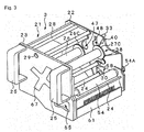
- FIG. 3 is a perspective view of the ribbon cassette apparatus 3 as seen in the direction of the printer main body 2 of the same
- FIG. 4 is a perspective view of the ribbon cassette apparatus 3 as seen from the printer main body 2 of the same
- FIG. 1 is a perspective view of a printer main body 2 and ribbon cassette apparatus 3 in a thermal transfer printer 1 in which the ribbon cassette apparatus 3 of a first embodiment of the present invention is assembled
- FIG. 2 is a front view as seen in the direction from the ribbon cassette apparatus 3 to the printer main body 2 of the same
- FIG. 3 is a perspective view of the ribbon cassette apparatus 3 as seen in the direction of the printer main body 2 of the same
- FIG. 4 is a perspective view of the ribbon cassette apparatus
- FIG. 5 is an exploded perspective view of the ribbon cassette apparatus 3 as seen in the direction of the printer main body 2 of the same
- FIG. 6 is an exploded perspective view of the ribbon cassette apparatus 3 as seen from the direction of the printer main body 2 of the same.
- FIG. 2 has been drawn without consideration of the front-to-rear relationships of each member in the printer main body 2 direction.
- the thermal transfer printer 1 comprises a printer main body 2, ribbon cassette apparatus 3, and cover 4 of a rectangular (U-shaped) cross-section mounted on the printer main body 2.
- the printer main body 2 comprises a cassette attachment face 5 formed from a side frame parallel to the direction of transport of a printing sheet L and thermal transfer ribbon R ( FIG. 2 ), a base frame 6, main guide shaft 7, printer main body stay 8, final positioning face 9, final positioning engagement pin 10, thermal head 11, platen roller 12, head opening/shutting lever 13 and operating panel 14.
- FIG. 5 and FIG. 6 have been drawn omitting the cover 4 and the operating panel 14.
- the base frame 6 orthogonally intersects with the cassette attachment face 5 and is fixed by a cantilever method so as to be positioned in FIG. 1 in the lower part of the ribbon cassette apparatus 3.
- the main guide shaft 7 protrudes in a comparatively long length from the cassette attachment face 5 in the direction of the ribbon cassette apparatus 3 across the base frame 6.
- the printer main body stay 8, of which the upper surface is wide and of a comparatively broad surface area, is fixed by a cantilever method to orthogonally intersect with the cassette insertion face 5.
- the final positioning face 9 is positioned in the side face of the printer main body stay 8, is configured from another side frame that orthogonally intersects with the printer main body stay 8, and opposes the ribbon cassette apparatus 3.
- the final positioning engagement pin 10 protrudes from the final positioning face 9 in the direction of the ribbon cassette apparatus 3 so as to be able to maintain the high precision of the final mounted position of the ribbon cassette apparatus 3.
- the thermal head 11 is turnable in the opening/shutting direction (separating direction and pressing direction with respect to the platen roller 12) about a head opening/shutting spindle 15 provided to extend between the cassette attachment face 5 and the final positioning face 9.
- a ribbon-like thermal transfer ribbon R being similarly able to be loaded between the thermal head 11 and platen roller 12 employing a ribbon cassette apparatus 3.
- the printing sheet L and thermal transfer ribbon R are held between the thermal head and the platen roller 12 and transported along a transport path 16 enabling printing to be performed on the printing sheet L.
- the thermal head 11 is approach/separated opened and shut with respect to the platen roller 12
- the head opening/shutting lever 13 By the turnable operation of the head opening/shutting lever 13 in the forward and reverse directions around a lever shaft 17 provided to extend from the cassette attachment face 5 and final positioning face 9, the thermal head 11 being able to be pressed onto the platen roller 12 at a predetermined printing pressure.
- the head opening/shutting lever 13 is concentric with a section of the lever shaft 17 and integrally operable with the cassette attachment lever 63 as a result of the provision of small space (base plate interval 64, see FIG. 11 ) provided in the axial direction therebetween.
- the operating panel 14 comprises a display 18 and operating keys 19 and is used for performing printing and various controls on the printer main body 2.
- Mounting holes 20 are formed in each of the four corners of the printer main body 2 (cassette attachment face 5) side and in other positions in accordance with need facilitating an assembly in which the printer main body 2 (ribbon cassette apparatus 3) is able to be connected with predetermined peripheral apparatus (for example label affixing apparatus not shown in the diagram) at arbitrary positions.
- the ribbon cassette apparatus 3 comprises a cassette main body 21, and this cassette main body 21 comprises a printer-side base plate 22, handle-side base plate 23, and a plurality of support shafts 24 (for example, see FIG. 3 and FIG. 4 ).
- the printer-side base plate 22 extends along the direction of transport of the printing sheet L and thermal transfer ribbon R and opposes the cassette attachment face 5 of the printer main body 2.
- the handle-side base plate 23 comprises a pair of handles 25 that oppose the printer-side base plate 22 by way of the support shafts 24 and that are used for the attachment operation of the cassette main body 21 in the printer main body 2.
- the support shafts 24 fix the printer-side base plate 22 and the support shaft 24 (sic) at an interval of no less than the width of the printing sheet L and the thermal transfer ribbon R.
- the cassette main body 21 facilitates the attachment of a ribbon supply spindle 26 for supplying the thermal transfer ribbon R to the transport path 16 of the thermal transfer ribbon R and a winding supply spindle 27 for winding the thermal transfer ribbon R transported along the transport path 16 between the printer-side base plate 22 and handle-side base plate 23.
- the cassette main body 21 further comprises a cassette main body stay 28 having an upper surface of comparatively broad surface area.
- the cassette main body stay 28 is positioned between the printer-side base plate 22 and handle-side base plate 23, a main guide hole 29 to which the main guide shaft 7 that protrudes from the printer main body 2 side in the cassette main body 21 direction is insertable being formed therein.
- the inserted state of the main guide shaft 7 in the main guide hole 29 is facilitated easily by forming of the tip-end part thereof in a tapered shape. Moreover, an end part of the main guide hole 29 of the cassette main body stay 28 on the opposing side to the printer main body 2 is open and this facilitates a smooth insertion of the main guide shaft 7 in the main guide hole 29.
- a final positioning engagement hole 31 ( FIG. 6 ) is formed in the inner wall face side of the handle-side base plate 23 opposing the final positioning engagement pin 10 formed in the printer main body stay 8 of the printer main body 2 (final positioning face 9).
- a printer main body opposing face 32 that opposes the printer main body 2 of the printer-side base plate 22 comprises a plurality (two in the example of the diagram) of assist engagement pins 33 ( FIG. 6 ) provided toward the printer main body 2 side, and assist engagement holes 34 ( FIG. 5 ) engageable with the assist engagement pins 33 are formed in the cassette attachment face 5 of the printer main body 2.
- a magnet 35 ( FIG. 5 ) is provided in the cassette attachment face 5 of the printer main body 2 and an iron piece 36 ( FIG. 6 ) is provided in the printer main body opposing face 32 of the printer-side base plate 22 to facilitate the adsorption of the cassette main body 21 (printer main body opposing face 32) to the printer main body 2 (cassette attachment face 5).
- FIG. 7 is a main part perspective view of the cassette main body 21 as seen from the direction of the printer main body 2 in a state in which the thermal transfer ribbon R has not been loaded into the cassette main body 21, and
- FIG. 8 is a main part perspective view of the cassette main body 21 as seen from the printer main body 2 of the same.
- a supply spindle guide groove 37 and winding spindle guide groove 38 ( FIG. 5, FIG.
- spindle receiving members left-right pair of supply spindle receiver members 39 and winding spindle receiver members 40 in the respective axial directions thereof able to fix the ribbon supply spindle 26 and the winding supply spindle 27 to their respective set positions are also provided.
- the supply spindle receiver member 39 comprises a circular arc-shaped spindle part 39A that is inserted and fixed in a supply spindle receiving hole 41 formed in the rearmost part of the supply spindle guide groove 37, and a pair of guide flank parts 39B that extend outward along the supply spindle guide groove 37 from the two end parts of the circular arc-shaped spindle part 39A.
- the winding spindle receiver member 40 comprises a circular arc-shaped spindle part 40A that is inserted and fixed in a winding spindle receiving hole 42 formed in the rearmost part of the winding spindle guide groove 38, and a pair of guide flank parts 40B that extend outward along the supply spindle guide groove 38 from the two end parts of the circular arc-shaped spindle part 40A.
- the supply spindle receiver member 39 and winding spindle receiver member 40 fixed in the inner wall face of the printer-side base plate 22 are narrower in width than the supply spindle receiver member 39 and winding spindle receiver member 40 fixed in the inner wall face of the handle-side base plate 23.
- the guide flank part 39B of the supply spindle receiver member 39 and the guide flank part 40B of the winding spindle receiver member 40 fixed in the inner wall face of the printer-side base plate 22 are smaller than the guide flank part 39B of the supply spindle receiver member 39 and the guide flank part 40B of the winding spindle receiver member 40 fixed in the inner wall face of the handle-side base plate 23.
- a plurality of axial direction protrusions 39C and protrusions 40C are formed protrudingly in the inner circumferential surface side of the circular arc-shaped spindle part 39A and circular arc-shaped spindle part 40A and, as a result of being engageable with a supply spindle circumferential groove 26A and winding spindle circumferential groove 27A formed in each of the end parts of the handle-side base plate 23 side of the ribbon supply spindle 26 and ribbon winding spindle 27, the ribbon supply spindle 26 and winding supply spindle 27 are fixable to a section of the supply spindle receiver member 39 and winding spindle receiver member 40 and are prevented from easily falling out.
- follower gears (supply spindle follower gear 26B, winding spindle follower gear 27B) are formed in the end parts of the printer main body 2 (cassette attachment face 5) side of the ribbon supply spindle 26 and the winding supply spindle 27.
- the supply spindle follower gear 26B and winding spindle follower gear 27B are engageable by way of the supply spindle receiving hole 41 and the winding spindle receiving hole 42 respectively with follower gears (supply spindle driver gear 43, supply spindle driver gear 44) that face the cassette attachment face 5 of the printer main body 2.
- detection gears (supply spindle detection gear 26C, winding spindle detection gear 27C) of larger diameter than the supply spindle follower gear 26B and winding spindle follower gear 27B are formed in the end parts of the ribbon supply spindle 26 and the winding supply spindle 27 to be engageable by way of open windows (supply spindle open window 47, winding spindle open window 48) with sensor-side gears (supply spindle sensor-side gear 45, winding spindle sensor-side gear 46).
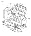
- FIG. 9 is a main part expanded perspective view of the supply spindle driver gear 43 and winding spindle driver gear 44, as well as the supply spindle sensor-side gear 45 and winding spindle sensor-side gear 46 components facing the cassette attachment face 5 of printer main body 2
- FIG. 10 is a main part expanded perspective view of the supply spindle follower gear 26B and winding spindle follower gear 27B components that face the printer main body opposing face 32 of the cassette main body 21 (printer-side base plate 22).
- the supply spindle driver gear 43 comprises an engagement center pin 43A that protrudes from the center part thereof, and an engagement gear 43B that is formed slightly lower in the circumference of the engagement center pin 43A.
- the winding spindle driver gear 44 comprises an engagement center pin 44A that protrudes from the center part thereof, and an engagement gear 44B that is formed slightly lower in the circumference of the engagement center pin 44A.
- an engagement center hole 26D and engagement center hole 27D are formed in the center part of the supply spindle follower gear 26B and winding spindle follower gear 27B in the ribbon supply spindle 26 and winding supply spindle 27 to facilitate engagement with the engagement center pin 43A and the engagement center pin 44A respectively.
- the adoption of a tapered shape end part of each of the engagement center pin 43A and engagement center pin 44A the engagement thereof with the engagement center hole 26D and engagement center hole 27D respectively is simple and reliable.
- Detection discs comprising slits in the circumference are concentrically mounted with the supply spindle sensor-side gear 45 and the winding spindle sensor-side gear 46 respectively, and detection of the rotation state of the ribbon supply spindle 26 and winding supply spindle 27 being facilitated by rotation sensors (supply spindle rotation sensor 51, winding spindle rotation sensor 52).
- the ribbon supply spindle 26 and winding supply spindle 27 are divided between the printer-side base plate 22 and handle-side base plate 23 (details omitted), and these divided components are independently rotatable structures. Accordingly, whenever the supply spindle circumferential groove 26A is engaged with the circular arc-shaped spindle part 39A and the winding spindle circumferential groove 27A is engaged with the circular arc-shaped spindle part 40A (see FIG. 6 ) in the handle-side base plate 23 side and, furthermore, with reference to FIG. 5 and FIG.
- each of the ribbon supply spindle 26 and winding supply spindle 27 are rotatable between the printer-side base plate 22 and the handle-side base plate 23 to facilitate the supply and winding of the thermal transfer ribbon R.
- transport assist rollers (upstream-side assist roller 53, and downstream-side assist roller 54) to assist in transporting of the thermal transfer ribbon R are provided between the printer-side base plate 22 and handle-side base plate 23 in the upstream side and downstream side of the platen roller 12 along the transport path 16 of the thermal transfer ribbon R. That is to say, the upstream-side assist roller 53 and downstream-side assist roller 54 are rotatably supported between the printer-side base plate 22 and handle-side base plate 23, and follower gears (upstream side follower gear 53A, downstream-side follower gear 54A) are each formed in the printer main body 2 side of the upstream-side assist roller 53. As shown in FIG.
- the upstream-side assist roller 53 and downstream-side assist roller 54 are rotatably-drivable by means of the follower gears (upstream-side driver gear 55, downstream-side driver gear 56) that face the cassette attachment face 5 of the printer main body 2.
- the upstream-side follower gear 53A of the upstream-side assist roller 53 is engageable with the upstream-side driver gear 55 by way of an opposing face gear 57 provided in the printer main body opposing face 32 of the printer-side base plate 22 ( FIG. 6 ) and a timing belt 58 ( FIG. 5 ) provided in the side opposing the handle-side base plate 23 on the opposing side to the printer main body opposing face 32 of the printer-side base plate 22.
- the downstream-side follower gear 54A of the downstream-side assist roller 54 is directly engageable with the downstream-side driver gear 56.
- a guide pin 59 of which the tip-end part is formed in a tapered shape is protrudingly provided from the cassette attachment face 5 of the printer main body 2 in the region of the magnet 35, and a through-hole 60 ( FIG. 6 , FIG. 10 ) with which the guide pin 59 is engageable is formed in the printer-side base plate 22 whereupon, when the cassette main body 21 is moved toward and abuts the cassette attachment face 5, a reliable adsorption is established between the magnet 35 and iron piece 36 and a reliable engagement of the upstream-side assist roller 53 and downstream-side assist roller 54 with the upstream-side driver gear 55 and downstream-side driver gear 56 is established.
- a brush member 61 which performs an anti-static action on the thermal transfer ribbon R is provided in the downstream side of the platen roller 12 to extend across the transport path 16 of the thermal transfer ribbon R.
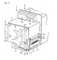
- FIG. 11 is a main part expanded perspective view of the head opening/shutting lever 13 component, the head opening/shutting lever 13 being attachable with a lever fixing pin 62 protrudingly fixed in the base frame 6 so that the thermal head 11 is able to be pressed at a predetermined pressure on the platen roller 12.
- the cassette attachment lever 63 is concentrically provided about the lever shaft 17 of the head opening/shutting lever 13, the cassette attachment lever 63 and head opening/shutting lever 13 being connected to be integrally operable. Accordingly, a head lock (approach/separate operation) between the thermal head 11 and platen roller 12 and a cassette lock (mounting operation) of the cassette main body 21 in the printer main body 2 can be jointly implemented by operation of this single cassette attachment lever 63. This facilitates improvement to the assembly workability and a reduction in the number of assembly steps.
- the base plate interval 64 slightly larger than the thickness of the printer-side base plate 22 of the cassette main body 21 is provided between the head opening/shutting lever 13 and the cassette attachment lever 63. Accordingly, as a result of the base plate interval 64 section being positioned in the printer-side base plate 22 subsequent to the cassette attachment lever 63 being operated in the lock direction (anti-clockwise direction in FIG.
- FIG. 12 is a perspective view showing a state in which the cassette attachment lever 63 is operated after the cassette main body 21 (ribbon cassette apparatus 3) has been inserted in the printer main body 2, the head opening/shutting lever 13 integral with the cassette attachment lever 63 being engaged with the lever fixing pin 62 to complete the mounted state of the ribbon cassette apparatus 3 in the printer main body 2 as a result of the turning operation of the cassette attachment lever 63 from the virtual line to the state shown by the solid line in the diagram.
- the cover 4 mounted on the cassette attachment face 5 of the printer main body 2 fulfils a dust-prevention and waterproofing function, and an insert opening hole 66 is formed in the cassette main body 21 to facilitate guiding of the cassette main body 21 to the printer main body 2 side. That is to say, when the cassette main body 21 is directed toward the printer main body 2 side and is subsequently moved toward the printer main body 2, the guide direction and position of the cassette main body 21 is clearly indicatable to an operator performing the mounting through the cover 4 itself and, in reality, a guiding of the left and right edge parts and upper edge part of the printer-side base plate 22 and handle-side base plate 23 of the cassette main body 21 is performed.
- a transparent window 67 that facilitates confirmation from the exterior with the naked eye of the thermal transfer ribbon R in the interior of the cover 4 is formed in the approximate center part of the handle-side base plate 23.
- an equivalent transparent window can also be formed in the upper part of the cover 4.
- a thermal transfer printer 1 printer main body 2 and ribbon cassette apparatus 3 of this configuration
- the mounting of the ribbon cassette apparatus 3 in the printer main body 2 is based on the handles 25 being held and the cassette main body 21 being operated in the printer main body 2 direction. That is to say, first, the main guide hole 29 of the cassette main body stay 28 is engaged with the cassette main body 21 of the main guide shaft 7 of the printer main body 2 and, furthermore, the guide cut-away part 30 of the printer-side base plate 22 is moved along the upper surface of the printer main body stay 8 and the arc-shaped end part 8A thereof as the cassette main body 21 is moved toward the cassette attachment face 5 of the printer main body 2.
- the cassette main body 21 is able to be attached to the printer main body 2 as a result of the engagement of the assist engagement pins 33 of the printer-side base plate 22 with the assist engagement holes 34 in the cassette attachment face 5 of the printer main body 2 and, in addition, the engagement of the guide pin 59 in the cassette attachment face 5 with the through-hole 60 in the printer-side base plate 22 and, furthermore, the engagement of the final positioning engagement pin 10 of the printer main body stay 8 with the final positioning engagement hole 31 of the handle-side base plate 23, the cassette main body 21 being opposed to the printer main body 2 with a predetermined position accuracy with adsorption between the magnet 35 and the iron piece 36.
- the follower gears (supply spindle follower gear 26B, winding spindle follower gear 27B) of the ribbon supply spindle 26 and winding supply spindle 27 are engaged with the drive gears (supply spindle driver gear 43, winding spindle driver gear 44) of the printer main body 2, and the detection gears thereof (supply spindle detection gear 26C, winding spindle detection gear 27C) are engaged with the sensor gears (supply spindle sensor-side gear 45, winding spindle sensor-side gear 46 ) of the printer main body 2.
- Removal of the cassette main body 21 from the printer main body 2 involves, upon release of the cassette lock and head lock by a turning operation of the cassette attachment lever 63 in the clockwise direction of FIG. 12 , the handles 25 being held and the cassette main body 21 as a whole being pulled out from the printer main body 2 whereupon, conversely to that described above, the adsorption and engagements between the cassette main body 21 and printer main body 2 are released to allow the cassette main body 21 to be removed.
- the cassette main body 21 can be attached to the printer main body 2 with a predetermined relative positional accuracy. Furthermore, the ribbon supply spindle 26 and winding supply spindle 27 can be set in advance in the cassette main body 21, and the operation for the replacement of the thermal transfer ribbon R can be implemented easily.
- the mounting operation itself of the cassette main body 21 is a simple operation requiring simply a pushing thereof while the handles 25 are being held, the cassette main body 21 can be easily mounted without affect on the position and positional arrangement of the printer main body 2.
- the mounting operation in which the cassette main body 21 is moved toward the printer main body 2 side can be stably performed.
- FIG. 13 is a front view of a ribbon cassette apparatus 70 based on a second embodiment of the present invention in which, in addition to the previously described configuration, that is to say, a configuration in which the lever fixing pin 62 is provided in the base frame 6 of a printer main body 2 and the head opening/shutting lever 13 is attachably provided in the lever fixing pin 62 so that the thermal head 11 is able to be maintained in a pressed state at a predetermined pressure in the platen roller 12, in the ribbon cassette apparatus 70 the base frame 6 and cassette main body 21 may be firmly fixed to each other.
- the handle-side base plate 23 is able to be fixed to the base frame 6 by the provision of an assist opening/shutting lever 71 in the handle-side base plate 23 in the upstream-side of the transport path 16 from the platen roller 12 part that is turnably operable around an assist lever shaft 72, and the provision of an assist lever pin 73 in the base frame 6 and engagement of the assist lever pin 73 and the assist opening/shutting lever 71.
- the vibration of the base frame 6 component accompanying printing on the thermal transfer ribbon R and the transport thereof and, furthermore, the possibility of the vibration increasing in the thermal transfer printer 1 as a whole accompanying an increase in the size of the thermal transfer ribbon R and the cassette main body 21 can be suppressed, and undesirable effects to the printing on the thermal transfer ribbon R and the transport thereof in the thermal transfer printer 1 can be avoided.
- FIG. 14 is a main part expanded view of the cassette main body stay 28 as seen from the printer main body 2 side in a ribbon cassette apparatus 80 based on a third embodiment of the present invention in which, in the ribbon cassette apparatus 80, a rubber cushion member or other elastic member 81 is mounted to abut the opening edge part in particular of the main guide hole 29 of the cassette main body stay 28 in the printer-side base plate 22 of the cassette main body 21 thereof facing the cassette attachment face 5 of the printer main body 2.
- FIG. 15 is a main part expanded perspective view of the cassette main body stay 28 component as seen in the printer main body 2 direction, an end part of the main guide hole 29 of the cassette main body stay 28 of the opposing side to the printer main body 2 being closed.
- the impact noise generated when the cassette main body 21 is attached to the printer main body 2 can be suppressed, the wear of the cassette main body 21 (printer-side base plate 22) can be suppressed, and the durability thereof can be improved by the elastic member 81. Furthermore, because the main guide hole 29 is opened only in the printer-side base plate 22 the residual air within the main guide hole 29 performs an air-damper action accompanying the engagement of the main guide hole 29 and main guide shaft 7 and, accordingly, even if the operation for mounting the ribbon cassette apparatus 80 in the printer main body 2 is performed quickly, the speed of insertion thereof is slowed as it is inserted and, in the end, a gentle insertion action that allows the mounting operation to be completed with reduced impact is facilitated.
Landscapes
- Physics & Mathematics (AREA)
- Optics & Photonics (AREA)
- Impression-Transfer Materials And Handling Thereof (AREA)
- Electronic Switches (AREA)
Abstract
Description
- The present invention relates to a thermal transfer printer ribbon cassette apparatus and a ribbon cassette mounting method, and more particularly to a thermal transfer printer ribbon cassette apparatus and a ribbon cassette mounting method by which the mounting operation of a ribbon cassette main body to a printer main body is simple and reliable.
- Thermal transfer ribbons loaded in conventional thermal transfer printers are thin and, as a result, a snaking and wrinkling thereof occurs readily accompanying its supply to the transport path and its winding from the transport part. Accordingly, the stable transport of wide thermal transfer ribbons in particular is afforded by the adoption of a system as described in, for example, Japanese Unexamined Patent Application No.
2006-82297 - However, there are problems inherent to the loading of a ribbon cassette such as this in a printer in that it engenders a further demand for simplifying of the attachment operation thereof to shorten the ribbon replacement time and a simplification of the operation for loading the thermal transfer ribbon into the ribbon cassette itself.
There are problems inherent to the use of a thermal transfer printer and so on in assembly with various types of peripheral apparatus (for example label affixing apparatus) in factories or manufacturing sites in particular in that, as a consequence of the need for the thermal transfer ribbon to be loaded in large rolls of large diameter (for example, 1000m winding or the like) and the increased weight thereof, better operability and convenience of the mounting operation of the ribbon cassette is desirable. - A further problem arises if the thermal transfer printer is installed in a narrow space from the viewpoint of the difficult of the attachment operation of the ribbon cassette.
An additional problem arises if the thermal transfer printer itself is three-dimensionally installed in a range of positions from the viewpoint of the need to further simplify the implementation of the attachment operation of the ribbon cassette.
More specifically, there is a problem from the viewpoint of the need for a simple and reliable mounting operation based on a simple guide mechanism when, as an initial stage mounting operation, the ribbon cassette is moved toward the thermal transfer printer. - While the mounting of the ribbon cassette in the thermal transfer printer necessitates the thermal head and the platen roller of a printing unit of the printer being established in a mutually separated state and, following the mounting of the ribbon cassette, the thermal head and platen roller being again closed in a predetermined pressed state and, in addition, the ribbon cassette eventually being fixed in the printer, from the viewpoint of convenience of the operation the separate implementation of the approach/separate operation of the thermal head and the platen roller and the final mounting and fixing operation of the ribbon cassette on the thermal transfer printer should be avoided, and in this respect as well there is a need for improved convenience of the operations.
- Furthermore, when the thermal transfer ribbon is used in a large roll of increased weight the possibility arises that thermal transfer ribbon mounted in the ribbon cassette will fall from each of the ribbon supply spindle and the ribbon winding spindle through the cassette main body side while being handled and, accordingly, there is an inherent problem from the viewpoint of a need for simplicity and reliability of the structures for mounting and fixing (inserting) and operations for mounting and fixing (inserting) the ribbon supply spindle and the ribbon winding spindle in the cassette main body.
- While there is a need, because the ribbon supply spindle and ribbon winding spindle are mounted in the ribbon cassette side, for the ribbon supply spindle and ribbon winding spindle rotation drive mechanisms to be linked when the ribbon cassette is mounted and fixed on the printer side and a structure for engaging-disengaging gear mechanisms between the printer and the ribbon cassette is normally used for this person, there is a problem from the viewpoint of a need for, when the ribbon cassette is being mounted on the thermal transfer printer, the mounting operation based on a smooth engagement of these gear mechanisms with each other to be able to be implemented reliably.
- There is a further problem inherent thereto from the viewpoint of the possibility of increased impact noise being generated during the final mounting of the ribbon cassette on the thermal transfer printer accompanying increases in size and weight of the thermal transfer ribbon and ribbon cassette and the need to eliminate this impact noise.
- In addition, there a further inherent problem thereto from the viewpoint of the increased vibration generated in the thermal transfer printer main body associated with the transport and printing of the thermal transfer ribbon and print sheet accompanying increases in size and weight of the thermal transfer ribbon and ribbon cassette and the unwanted unavoidable effects thereof on the printing of the printing sheet and transport thereof in the thermal transfer printer.
- 1 : JPA2006-82297

- With the foregoing problems in mind, it is an object of the present invention to provide a thermal transfer printer ribbon cassette apparatus and method of ribbon cassette mounting in which the operations for loading and replacement of the thermal transfer ribbon can be implemented easily.
- A further object of the present invention is to provide a thermal transfer printer ribbon cassette apparatus and method of ribbon cassette mounting in which the loading processing and replacement processing is possible in a short time.
- Another object of the present invention is to provide a thermal transfer printer ribbon cassette apparatus and method of ribbon cassette mounting in which both the operation for loading of the ribbon in the ribbon cassette itself and the operation for loading the cassette itself in the printer main body can be efficiently implemented.
- Another object of the present invention is to provide a thermal transfer printer ribbon cassette apparatus and method of ribbon cassette mounting in which a ribbon cassette comprising a large roll thermal transfer ribbon in particular is able to be simply and reliably mounted in the thermal transfer printer side.
- Another object of the present invention is to provide a thermal transfer printer ribbon cassette apparatus and method of ribbon cassette mounting in which, if the thermal transfer printer is installed in a narrow space, or if the thermal transfer printer itself is three-dimensionally installed in a range of positions, the insert-attach operation of the ribbon cassette is able to be executed even more simply.
- Another object of the present invention is to provide a thermal transfer printer ribbon cassette apparatus and method of ribbon cassette mounting in which a simple and reliable mounting operation based on a simple guide mechanism is possible when, as an initial stage mounting operation, the ribbon cassette is moved toward the thermal transfer printer.
- Another object of the present invention is to provide a thermal transfer printer ribbon cassette apparatus and method of ribbon cassette mounting in which the approach/separate operation of the thermal head and platen roller in the thermal transfer printer and final mounting and fixing operation of the ribbon cassette on the thermal transfer printer is able to be implemented in a simple operation.
- Another object of the present invention is to provide a thermal transfer printer ribbon cassette apparatus and method of ribbon cassette mounting in which the possibility of the thermal transfer ribbon falling from each of the ribbon supply spindle and ribbon winding spindle through the cassette main body side is avoided, and the simplicity and reliability of the structures for mounting and fixing (inserting-removing) the ribbon supply spindle and the ribbon winding spindle on the cassette main body and the operations for the mounting and fixing (inserting-removing) thereof can be ensured.
- Another object of the present invention is to provide a thermal transfer printer ribbon cassette apparatus and method of ribbon cassette mounting in which the gear mechanisms during mounting of the ribbon cassette in the thermal transfer printer can be smoothly engaged with each other.
- Another object of the present invention is to provide a thermal transfer printer ribbon cassette apparatus and method of ribbon cassette mounting in which the impact noise of which there is a possibility of being generated during the final mounting of the ribbon cassette on the thermal transfer printer is able to be reduced.
- And another object of the present invention is to provide a thermal transfer printer ribbon cassette apparatus and method of ribbon cassette mounting in which unwanted effects due by vibration generated in the thermal transfer printer as a whole are prevented from extending to the printing of the printing sheet and transport thereof in the thermal transfer printer.
- That is to say, the present invention focuses on the provision of a three-stage guide structure and engagement structure broadly based on, as a cassette main body is moved toward a printer main body for the mounting therein, the use of a main guide shaft protruding in a comparatively long length from the printer main body side in the cassette main body direction being as an initial guide and then guidability along a level and comparatively wide printer main body stay and, finally, engageability of a final positioning engagement pin of high positioning precision formed in the printer main body stay and a final position engagement hole formed in a handle-side base plate, a first invention thereof constituting a thermal transfer printer ribbon cassette apparatus releasably attached to a thermal transfer printer which comprises a printer main body where a thermal head and a platen roller are mounted and where a printing sheet and a thermal transfer ribbon are held between the thermal head and the platen roller and are transported, and which performs printing on the printing sheet, a cassette main body being formed by a printer-side base plate that extends along a direction of transport of the printing sheet and the thermal transfer ribbon and that opposes a cassette attachment face of the printer main body, a handle-side base plate that opposes the printer-side base plate and that comprises handles for an attachment/detachment operation, and a support shaft for fixing the handle-side base plate and the printer-side base plate with a gap not less than the width of the thermal transfer ribbon and the printing sheet, the cassette main body comprising a ribbon supply spindle for supplying the thermal transfer ribbon to a transport path for the thermal transfer ribbon and a ribbon winding spindle for winding the thermal transfer ribbon transported to this transport path that are able to be releasably disposed between the handle-side base plate and the printer-side base plate, and a cassette main body stay positioned between the handle-side base plate and the printing-side base plate in which a main guide hole into which a main guide shaft protruding from the printer main body side in the cassette main body direction is fit removably is formed, a guide cut-away part guidable along the printer main body stay formed from the printer main body side toward the printer-side base plate being formed in the printer-side base plate, a final positioning engagement pin being formed in the printer main body stay of the printer main body, and a final positioning engagement hole being formed in the handle-side base plate, the cassette main body being releasably attached to in the printer main body by engagement/disengagement of the main guide shaft of the printer main body with and from the main guide hole of the cassette main body stay and by engagement/disengagement of the final positioning engagement pin of the printer main body stay with and from the final positioning engagement hole of the handle-side base plate.
- A second invention constitutes a thermal transfer printer ribbon cassette mounting method for setting the thermal transfer printer ribbon to a thermal transfer printer, which comprises a printer main body where a thermal head and a platen roller are mounted and where a printing sheet and a thermal transfer ribbon are held between the thermal head and the platen roller and are transported, and which performs printing on the printing sheet, the method comprising: forming a cassette main body by providing a printer-side base plate that extends along a direction of transport of the printing sheet and the thermal transfer ribbon and that opposes a cassette attachment face of the printer main body, a handle-side base plate that opposes the printer-side base plate and that comprises handles for an attachment/detachment operation, and a support shaft for fixing the handle-side base plate and the printer-side base plate with a gap not less than the width of the thermal transfer ribbon and the printing sheet; forming the cassette main body to comprise a ribbon supply spindle for supplying the thermal transfer ribbon to a transport path for the thermal transfer ribbon and a ribbon winding spindle for winding the thermal transfer ribbon transported to this transport path that are able to be releasably disposed between the handle-side base plate and the printer-side base plate, and a cassette main body stay positioned between the handle-side base plate and the printing-side base plate in which a main guide hole into which a main guide shaft protruding from the printer main body side in the cassette main body direction is fit removably is formed; forming a guide cut-away part guidable along the printer main body stay formed from the printer main body side toward the printer-side base plate in the printer-side base plate; forming a final positioning engagement pin in the printer main body stay of the printer main body, and a final positioning engagement hole in the handle-side base plate; operating the cassette main body by way of handles to engage the main guide shaft hole of the cassette main body stay with the main guide shaft of the printer main body; moving the guide cut-away part of the printer-side base plate along the printer main body stay as the cassette main body is moved nearer the cassette attachment face of the printer main body; and engaging the final positioning engagement hole of the handle-side base plate with the final positioning engagement pin of the printer main body stay so that the cassette main body can be attached to or detached from the printer main body.
- A cover, mounted in the printer main body, in which an opening is formed in the cassette main body side through which the cassette main body is guidable to the printer main body side can be provided.
- The printer-side base plate comprises an auxiliary engagement pin provided toward the printer main body side, an auxiliary engagement hole into which the assist engagement pin is engageable being formed in the cassette attachment face of the printer main body.
- A head opening/closing lever for a contact/separation operation of the thermal head and the platen roller and a cassette attachment lever for fixing the cassette main body to the printer main body are connected to be integrally operable.
- A supply spindle guide groove and a winding spindle guide groove along which the ribbon supply spindle and the ribbon winding spindle respectively are guidable in set directions thereof are formed in the inner-side wall face of the handle-side base plate and the printer-side base plate respectively, a spindle receiving member able to fix the ribbon supply spindle and the ribbon winding spindle to the respective set positions thereof being provided in the rearmost part of the supply spindle guide groove and the winding spindle guide groove.
- Driven gears are formed in the printer main body side end parts of each of the ribbon supply spindle and the ribbon winding spindle to be engageable with driver gears that face the cassette attachment face of the printer main body, the gear end parts of each of the driven gears and driver gears being formed in a tapered shape.
- A magnet is provided in at least one of the cassette attachment face of the printer main body and a printer main body opposing face opposing the printer main body of the printer-side base plate, the cassette main body being attachable to the printer main body.
- An elastic member is mounted in an opening edge part, toward the cassette attachment face of the printer main body, of the main guide hole of the cassette main body.
- An end part of the cassette main body stay on the opposing side to the printer main body of the main guide hole can be opened.
- An end part of the cassette main body stay on the opposing side to the printer main body of the main guide hole can be closed.
- A lever fixing pin is provided in the vicinity of the platen roller in a base frame of the printer main body, and a head opening/closing lever engaged with or disengaged from the lever fixing pin is provided so that the thermal head is able to be held in a pressed state at a predetermined pressure on the platen roller, the handle-side base plate being able to be fixed to the base frame by providing an auxiliary opening/closing lever in the handle-side base plate in a different position from that of the head opening/closing lever and an auxiliary lever fixing pin in the base frame and by engagement of the assist lever fixing pin and the auxiliary opening-closing lever.
- In the thermal transfer printer ribbon cassette apparatus and method of ribbon cassette mounting based on the present invention, because of the provision of a three-stage guide structure and engagement structure that is broadly based on the use of a main guide shaft protruding in a comparatively long length from the printer main body side in the cassette main body direction being as an initial guide and then guidability along a level and comparatively wide printer main body stay and, finally, engageability of a final positioning engagement pin of high positioning precision formed in the printer main body stay and a final position engagement hole formed in a handle-side base plate, even if the width and length of the thermal transfer ribbon is increased with a resultant increase in the size and weight of the ribbon cassette itself, a stable mounting operation in which the cassette main body itself is easily and reliably guided while being pushed in the printer main body direction can be executed simply by a simple operation based on the holding of handles on the handle-side base plate.
- According to the first invention in particular, because a main guide shaft, printer main body stay and final positioning engagement hole are provided in the printer main body side and, correspondent thereto, a main guide hole, guide cut-away part and final positioning engagement hole are formed in the cassette main body side, the cassette main body can be easily and reliably mounted in the printer main body by a sequential engagement and guiding thereof.
- According to the second invention in particular, provided the cassette main body as it is moved nearer to engage with the main guide hole and guide cut-away part uses the main guide shaft and guide cut-away part provided in the printer main body side as a guide, the final positioning engagement pin of the printer main body can be engaged with good positioning precision with the final positioning engagement hole of the cassette main body, and the cassette main body can be easily and reliably and stably mounted to the printer main body.
- The present invention constitutes a thermal transfer printer ribbon cassette apparatus and method of ribbon cassette mounting in which, as a result of a main guide shaft, printer main body stay and final positioning engagement hole provided in a printer main body side being guided to and sequentially engaged with a main guide hole, guide cut-away part and final positioning engagement hole respectively formed in a cassette main body side, the cassette main body can be stably mounted easily and reliably in the printer main body.
- A thermal transfer printer ribbon cassette apparatus and method of ribbon cassette mounting according to a first embodiment of the present invention will be hereinafter described with reference to
FIG. 1 to FIG. 12 .
FIG. 1 is a perspective view of a printermain body 2 andribbon cassette apparatus 3 in athermal transfer printer 1 in which theribbon cassette apparatus 3 of a first embodiment of the present invention is assembled,FIG. 2 is a front view as seen in the direction from theribbon cassette apparatus 3 to the printermain body 2 of the same,FIG. 3 is a perspective view of theribbon cassette apparatus 3 as seen in the direction of the printermain body 2 of the same,FIG. 4 is a perspective view of theribbon cassette apparatus 3 as seen from the printermain body 2 of the same,FIG. 5 is an exploded perspective view of theribbon cassette apparatus 3 as seen in the direction of the printermain body 2 of the same, andFIG. 6 is an exploded perspective view of theribbon cassette apparatus 3 as seen from the direction of the printermain body 2 of the same. To illustrate the relative positional relationships from the side of the respective members,FIG. 2 has been drawn without consideration of the front-to-rear relationships of each member in the printermain body 2 direction.
Thethermal transfer printer 1 comprises a printermain body 2,ribbon cassette apparatus 3, andcover 4 of a rectangular (U-shaped) cross-section mounted on the printermain body 2. - As shown in
FIG. 1 andFIG. 5 in particular, the printermain body 2 comprises acassette attachment face 5 formed from a side frame parallel to the direction of transport of a printing sheet L and thermal transfer ribbon R (FIG. 2 ), abase frame 6, main guide shaft 7, printer main body stay 8,final positioning face 9, finalpositioning engagement pin 10,thermal head 11,platen roller 12, head opening/shutting lever 13 andoperating panel 14.FIG. 5 and FIG. 6 have been drawn omitting thecover 4 and theoperating panel 14. - The
base frame 6 orthogonally intersects with thecassette attachment face 5 and is fixed by a cantilever method so as to be positioned inFIG. 1 in the lower part of theribbon cassette apparatus 3.
The main guide shaft 7 protrudes in a comparatively long length from thecassette attachment face 5 in the direction of theribbon cassette apparatus 3 across thebase frame 6.
The printer main body stay 8, of which the upper surface is wide and of a comparatively broad surface area, is fixed by a cantilever method to orthogonally intersect with thecassette insertion face 5.
Thefinal positioning face 9 is positioned in the side face of the printer main body stay 8, is configured from another side frame that orthogonally intersects with the printer main body stay 8, and opposes theribbon cassette apparatus 3.
The finalpositioning engagement pin 10 protrudes from thefinal positioning face 9 in the direction of theribbon cassette apparatus 3 so as to be able to maintain the high precision of the final mounted position of theribbon cassette apparatus 3. - The
thermal head 11 is turnable in the opening/shutting direction (separating direction and pressing direction with respect to the platen roller 12) about a head opening/shutting spindle 15 provided to extend between thecassette attachment face 5 and thefinal positioning face 9.
In the openedthermal head 11 state, labels, tags or other ribbon-like printing sheet L are loaded between thethermal head 11 andplaten roller 12, a ribbon-like thermal transfer ribbon R being similarly able to be loaded between thethermal head 11 andplaten roller 12 employing aribbon cassette apparatus 3.
In the closedthermal head 11 state, the printing sheet L and thermal transfer ribbon R are held between the thermal head and theplaten roller 12 and transported along a transport path 16 enabling printing to be performed on the printing sheet L.
Thethermal head 11 is approach/separated opened and shut with respect to theplaten roller 12 By the turnable operation of the head opening/shutting lever 13 in the forward and reverse directions around alever shaft 17 provided to extend from thecassette attachment face 5 andfinal positioning face 9, thethermal head 11 being able to be pressed onto theplaten roller 12 at a predetermined printing pressure. - As will be described later, the head opening/
shutting lever 13 is concentric with a section of thelever shaft 17 and integrally operable with thecassette attachment lever 63 as a result of the provision of small space (base plate interval 64, seeFIG. 11 ) provided in the axial direction therebetween. - The
operating panel 14 comprises adisplay 18 andoperating keys 19 and is used for performing printing and various controls on the printermain body 2. -
Mounting holes 20 are formed in each of the four corners of the printer main body 2 (cassette attachment face 5) side and in other positions in accordance with need facilitating an assembly in which the printer main body 2 (ribbon cassette apparatus 3) is able to be connected with predetermined peripheral apparatus (for example label affixing apparatus not shown in the diagram) at arbitrary positions. - As shown in
FIG. 5 and FIG. 6 , theribbon cassette apparatus 3 comprises a cassettemain body 21, and this cassettemain body 21 comprises a printer-side base plate 22, handle-side base plate 23, and a plurality of support shafts 24 (for example, seeFIG. 3 andFIG. 4 ).
The printer-side base plate 22 extends along the direction of transport of the printing sheet L and thermal transfer ribbon R and opposes thecassette attachment face 5 of the printermain body 2.
The handle-side base plate 23 comprises a pair ofhandles 25 that oppose the printer-side base plate 22 by way of thesupport shafts 24 and that are used for the attachment operation of the cassettemain body 21 in the printermain body 2.
Thesupport shafts 24 fix the printer-side base plate 22 and the support shaft 24 (sic) at an interval of no less than the width of the printing sheet L and the thermal transfer ribbon R. - The cassette
main body 21 facilitates the attachment of aribbon supply spindle 26 for supplying the thermal transfer ribbon R to the transport path 16 of the thermal transfer ribbon R and a windingsupply spindle 27 for winding the thermal transfer ribbon R transported along the transport path 16 between the printer-side base plate 22 and handle-side base plate 23.
The cassettemain body 21 further comprises a cassette main body stay 28 having an upper surface of comparatively broad surface area.
The cassettemain body stay 28 is positioned between the printer-side base plate 22 and handle-side base plate 23, amain guide hole 29 to which the main guide shaft 7 that protrudes from the printermain body 2 side in the cassettemain body 21 direction is insertable being formed therein.
The inserted state of the main guide shaft 7 in themain guide hole 29 is facilitated easily by forming of the tip-end part thereof in a tapered shape.
Moreover, an end part of themain guide hole 29 of the cassette main body stay 28 on the opposing side to the printermain body 2 is open and this facilitates a smooth insertion of the main guide shaft 7 in themain guide hole 29. - A guide cut-away
part 30 guidable along the upper surface and the arc-shapedend part 8A of the printer main body stay 8 formed from the printermain body 2 toward the printer-side base plate 22 and the circular arc-shaped end part thereof is formed in the printer-side base plate 22.
A final positioning engagement hole 31 (FIG. 6 ) is formed in the inner wall face side of the handle-side base plate 23 opposing the finalpositioning engagement pin 10 formed in the printer main body stay 8 of the printer main body 2 (final positioning face 9). - A printer main
body opposing face 32 that opposes the printermain body 2 of the printer-side base plate 22 comprises a plurality (two in the example of the diagram) of assist engagement pins 33 (FIG. 6 ) provided toward the printermain body 2 side, and assist engagement holes 34 (FIG. 5 ) engageable with the assist engagement pins 33 are formed in thecassette attachment face 5 of the printermain body 2. - A magnet 35 (
FIG. 5 ) is provided in thecassette attachment face 5 of the printermain body 2 and an iron piece 36 (FIG. 6 ) is provided in the printer mainbody opposing face 32 of the printer-side base plate 22 to facilitate the adsorption of the cassette main body 21 (printer main body opposing face 32) to the printer main body 2 (cassette attachment face 5). -
FIG. 7 is a main part perspective view of the cassettemain body 21 as seen from the direction of the printermain body 2 in a state in which the thermal transfer ribbon R has not been loaded into the cassettemain body 21, andFIG. 8 is a main part perspective view of the cassettemain body 21 as seen from the printermain body 2 of the same.
A supplyspindle guide groove 37 and winding spindle guide groove 38 (FIG. 5, FIG. 6 ) able to guide theribbon supply spindle 26 and windingsupply spindle 27 respectively in the set directions thereof are formed in the inner side wall face of the printer-side base plate 22 and handle-side base plate 23 respectively, spindle receiving members (left-right pair of supplyspindle receiver members 39 and windingspindle receiver members 40 in the respective axial directions thereof) able to fix theribbon supply spindle 26 and the windingsupply spindle 27 to their respective set positions are also provided. - More specifically, referring to
FIG. 5 as well asFIG. 6 , the supplyspindle receiver member 39 comprises a circular arc-shapedspindle part 39A that is inserted and fixed in a supplyspindle receiving hole 41 formed in the rearmost part of the supplyspindle guide groove 37, and a pair of guide flankparts 39B that extend outward along the supplyspindle guide groove 37 from the two end parts of the circular arc-shapedspindle part 39A. - Similarly, the winding
spindle receiver member 40 comprises a circular arc-shapedspindle part 40A that is inserted and fixed in a windingspindle receiving hole 42 formed in the rearmost part of the windingspindle guide groove 38, and a pair of guide flankparts 40B that extend outward along the supplyspindle guide groove 38 from the two end parts of the circular arc-shapedspindle part 40A. - However, the supply
spindle receiver member 39 and windingspindle receiver member 40 fixed in the inner wall face of the printer-side base plate 22 are narrower in width than the supplyspindle receiver member 39 and windingspindle receiver member 40 fixed in the inner wall face of the handle-side base plate 23.
Furthermore, theguide flank part 39B of the supplyspindle receiver member 39 and theguide flank part 40B of the windingspindle receiver member 40 fixed in the inner wall face of the printer-side base plate 22 are smaller than theguide flank part 39B of the supplyspindle receiver member 39 and theguide flank part 40B of the windingspindle receiver member 40 fixed in the inner wall face of the handle-side base plate 23.
A plurality of axial direction protrusions 39C andprotrusions 40C are formed protrudingly in the inner circumferential surface side of the circular arc-shapedspindle part 39A and circular arc-shapedspindle part 40A and, as a result of being engageable with a supply spindlecircumferential groove 26A and winding spindlecircumferential groove 27A formed in each of the end parts of the handle-side base plate 23 side of theribbon supply spindle 26 andribbon winding spindle 27, theribbon supply spindle 26 and windingsupply spindle 27 are fixable to a section of the supplyspindle receiver member 39 and windingspindle receiver member 40 and are prevented from easily falling out.
On the other hand, as shown inFIG. 6 in particular, follower gears (supplyspindle follower gear 26B, windingspindle follower gear 27B) are formed in the end parts of the printer main body 2 (cassette attachment face 5) side of theribbon supply spindle 26 and the windingsupply spindle 27.
As shown inFIG. 5 in particular, the supplyspindle follower gear 26B and windingspindle follower gear 27B, are engageable by way of the supplyspindle receiving hole 41 and the windingspindle receiving hole 42 respectively with follower gears (supplyspindle driver gear 43, supply spindle driver gear 44) that face thecassette attachment face 5 of the printermain body 2.
Furthermore, similarly to the supplyspindle follower gear 26B and windingspindle follower gear 27B, detection gears (supplyspindle detection gear 26C, windingspindle detection gear 27C) of larger diameter than the supplyspindle follower gear 26B and windingspindle follower gear 27B are formed in the end parts of theribbon supply spindle 26 and the windingsupply spindle 27 to be engageable by way of open windows (supply spindleopen window 47, winding spindle open window 48) with sensor-side gears (supply spindle sensor-side gear 45, winding spindle sensor-side gear 46). -
FIG. 9 is a main part expanded perspective view of the supplyspindle driver gear 43 and windingspindle driver gear 44, as well as the supply spindle sensor-side gear 45 and winding spindle sensor-side gear 46 components facing thecassette attachment face 5 of printermain body 2, andFIG. 10 is a main part expanded perspective view of the supplyspindle follower gear 26B and windingspindle follower gear 27B components that face the printer mainbody opposing face 32 of the cassette main body 21 (printer-side base plate 22).
As shown inFIG. 9 in particular, the supplyspindle driver gear 43 comprises anengagement center pin 43A that protrudes from the center part thereof, and anengagement gear 43B that is formed slightly lower in the circumference of theengagement center pin 43A.
The windingspindle driver gear 44 comprises anengagement center pin 44A that protrudes from the center part thereof, and anengagement gear 44B that is formed slightly lower in the circumference of theengagement center pin 44A.
As shown inFIG. 10 in particular, anengagement center hole 26D andengagement center hole 27D are formed in the center part of the supplyspindle follower gear 26B and windingspindle follower gear 27B in theribbon supply spindle 26 and windingsupply spindle 27 to facilitate engagement with theengagement center pin 43A and theengagement center pin 44A respectively. Moreover, by the adoption of a tapered shape end part of each of theengagement center pin 43A andengagement center pin 44A, the engagement thereof with theengagement center hole 26D andengagement center hole 27D respectively is simple and reliable.
Furthermore, by the adoption of a tapered shape gear end part of each of the follower gears (supplyspindle follower gear 26B, windingspindle follower gear 27B) and theengagement gear 43B andengagement gear 44B of the driver gears (supplyspindle driver gear 43, winding spindle driver gear 44), the engagement operations therebetween can be implemented easily and reliably irrespective of the turning position (position in the circumferential direction) of theribbon supply spindle 26 and the windingsupply spindle 27. - In addition, by the adoption of a tapered shape gear end part of each of also the supply
spindle detection gear 26C and windingspindle detection gear 27C and the supply spindle sensor-side gear 45 and winding spindle sensor-side gear 46 of theribbon supply spindle 26 and windingsupply spindle 27 respectively, the engagement operations therebetween can be implemented easily and reliably.
Detection discs (supplyspindle detection disc 49, winding spindle detection disc 50) comprising slits in the circumference are concentrically mounted with the supply spindle sensor-side gear 45 and the winding spindle sensor-side gear 46 respectively, and detection of the rotation state of theribbon supply spindle 26 and windingsupply spindle 27 being facilitated by rotation sensors (supplyspindle rotation sensor 51, winding spindle rotation sensor 52). - The
ribbon supply spindle 26 and windingsupply spindle 27 are divided between the printer-side base plate 22 and handle-side base plate 23 (details omitted), and these divided components are independently rotatable structures.
Accordingly, whenever the supply spindlecircumferential groove 26A is engaged with the circular arc-shapedspindle part 39A and the winding spindlecircumferential groove 27A is engaged with the circular arc-shapedspindle part 40A (seeFIG. 6 ) in the handle-side base plate 23 side and, furthermore, with reference toFIG. 5 and FIG. 6 , whenever the supplyspindle follower gear 26B is engaged with the supplyspindle driver gear 43 and the windingspindle follower gear 27B is engaged with the windingspindle driver gear 44 in the printer-side base plate 22 side and, in addition, whenever the supply spindle sensor-side gear 45 is engaged with the supplyspindle detection gear 26C and the windingspindle detection gear 27C is engaged with the winding spindle sensor-side gear 46, each of theribbon supply spindle 26 and windingsupply spindle 27 are rotatable between the printer-side base plate 22 and the handle-side base plate 23 to facilitate the supply and winding of the thermal transfer ribbon R. - Moreover, as shown in
FIG. 2 ,FIG. 5 and FIG. 6 and other diagrams, transport assist rollers (upstream-side assistroller 53, and downstream-side assist roller 54) to assist in transporting of the thermal transfer ribbon R are provided between the printer-side base plate 22 and handle-side base plate 23 in the upstream side and downstream side of theplaten roller 12 along the transport path 16 of the thermal transfer ribbon R.
That is to say, the upstream-side assistroller 53 and downstream-side assistroller 54 are rotatably supported between the printer-side base plate 22 and handle-side base plate 23, and follower gears (upstreamside follower gear 53A, downstream-side follower gear 54A) are each formed in the printermain body 2 side of the upstream-side assistroller 53.
As shown inFIG. 5 in particular, the upstream-side assistroller 53 and downstream-side assistroller 54 are rotatably-drivable by means of the follower gears (upstream-side driver gear 55, downstream-side driver gear 56) that face thecassette attachment face 5 of the printermain body 2.
The upstream-side follower gear 53A of the upstream-side assistroller 53 is engageable with the upstream-side driver gear 55 by way of an opposingface gear 57 provided in the printer mainbody opposing face 32 of the printer-side base plate 22 (FIG. 6 ) and a timing belt 58 (FIG. 5 ) provided in the side opposing the handle-side base plate 23 on the opposing side to the printer mainbody opposing face 32 of the printer-side base plate 22.
The downstream-side follower gear 54A of the downstream-side assistroller 54 is directly engageable with the downstream-side driver gear 56. - As shown in
FIG. 2 ,FIG. 5 andFIG. 9 in particular, aguide pin 59 of which the tip-end part is formed in a tapered shape is protrudingly provided from thecassette attachment face 5 of the printermain body 2 in the region of themagnet 35, and a through-hole 60 (FIG. 6 ,FIG. 10 ) with which theguide pin 59 is engageable is formed in the printer-side base plate 22 whereupon, when the cassettemain body 21 is moved toward and abuts thecassette attachment face 5, a reliable adsorption is established between themagnet 35 andiron piece 36 and a reliable engagement of the upstream-side assistroller 53 and downstream-side assistroller 54 with the upstream-side driver gear 55 and downstream-side driver gear 56 is established.
In addition, abrush member 61 which performs an anti-static action on the thermal transfer ribbon R is provided in the downstream side of theplaten roller 12 to extend across the transport path 16 of the thermal transfer ribbon R. -
FIG. 11 is a main part expanded perspective view of the head opening/shuttinglever 13 component, the head opening/shuttinglever 13 being attachable with alever fixing pin 62 protrudingly fixed in thebase frame 6 so that thethermal head 11 is able to be pressed at a predetermined pressure on theplaten roller 12.
Thecassette attachment lever 63 is concentrically provided about thelever shaft 17 of the head opening/shuttinglever 13, thecassette attachment lever 63 and head opening/shuttinglever 13 being connected to be integrally operable.
Accordingly, a head lock (approach/separate operation) between thethermal head 11 andplaten roller 12 and a cassette lock (mounting operation) of the cassettemain body 21 in the printermain body 2 can be jointly implemented by operation of this singlecassette attachment lever 63. This facilitates improvement to the assembly workability and a reduction in the number of assembly steps. - Furthermore, the
base plate interval 64 slightly larger than the thickness of the printer-side base plate 22 of the cassettemain body 21 is provided between the head opening/shuttinglever 13 and thecassette attachment lever 63.
Accordingly, as a result of thebase plate interval 64 section being positioned in the printer-side base plate 22 subsequent to thecassette attachment lever 63 being operated in the lock direction (anti-clockwise direction inFIG. 11 ) after the cassettemain body 21 has been pushed in the printermain body 2 direction until the printer mainbody opposing face 32 of the cassettemain body 21 has abutted thecassette attachment face 5 of the printermain body 2, that is to say, as a result of the head opening/shuttinglever 13 andcassette attachment lever 63 being positioned on the upper and lower faces of the printer-side base plate 22, the ribbon cassette apparatus 3 (cassette main body 21) as a whole is fixable to the printermain body 2 side and fallout of the cassettemain body 21 from the printermain body 2 side is prevented.
Moreover, a guide cut-away part 30 (FIG. 5 ) is formed in the printer-side base plate 22 and, when theribbon cassette apparatus 3 as a whole is moved toward the handle-side base plate 23 in the printermain body 2 direction, alever window part 65 through which the head opening/shuttinglever 13 and thecassette attachment lever 63 are able to pass (FIG. 5 ) in the opened state of thethermal head 11 with respect to theplaten roller 12 is formed whereupon, in the opened state of thethermal head 11 described above, a mounting operation of the cassettemain body 21 in which it is moved until abutting the printermain body 2 without colliding with the head opening/shuttinglever 13 and thecassette attachment lever 63 is possible. -
FIG. 12 is a perspective view showing a state in which thecassette attachment lever 63 is operated after the cassette main body 21 (ribbon cassette apparatus 3) has been inserted in the printermain body 2, the head opening/shuttinglever 13 integral with thecassette attachment lever 63 being engaged with thelever fixing pin 62 to complete the mounted state of theribbon cassette apparatus 3 in the printermain body 2 as a result of the turning operation of thecassette attachment lever 63 from the virtual line to the state shown by the solid line in the diagram. - As shown in
FIG. 1 in particular, thecover 4 mounted on thecassette attachment face 5 of the printermain body 2 fulfils a dust-prevention and waterproofing function, and aninsert opening hole 66 is formed in the cassettemain body 21 to facilitate guiding of the cassettemain body 21 to the printermain body 2 side.
That is to say, when the cassettemain body 21 is directed toward the printermain body 2 side and is subsequently moved toward the printermain body 2, the guide direction and position of the cassettemain body 21 is clearly indicatable to an operator performing the mounting through thecover 4 itself and, in reality, a guiding of the left and right edge parts and upper edge part of the printer-side base plate 22 and handle-side base plate 23 of the cassettemain body 21 is performed.
Moreover, atransparent window 67 that facilitates confirmation from the exterior with the naked eye of the thermal transfer ribbon R in the interior of thecover 4 is formed in the approximate center part of the handle-side base plate 23. Naturally, an equivalent transparent window can also be formed in the upper part of thecover 4. - In a
thermal transfer printer 1, printermain body 2 andribbon cassette apparatus 3 of this configuration, the mounting of theribbon cassette apparatus 3 in the printermain body 2 is based on thehandles 25 being held and the cassettemain body 21 being operated in the printermain body 2 direction.
That is to say, first, themain guide hole 29 of the cassettemain body stay 28 is engaged with the cassettemain body 21 of the main guide shaft 7 of the printermain body 2 and, furthermore, the guide cut-awaypart 30 of the printer-side base plate 22 is moved along the upper surface of the printermain body stay 8 and the arc-shapedend part 8A thereof as the cassettemain body 21 is moved toward thecassette attachment face 5 of the printermain body 2.
Next, the cassettemain body 21 is able to be attached to the printermain body 2 as a result of the engagement of the assist engagement pins 33 of the printer-side base plate 22 with the assist engagement holes 34 in thecassette attachment face 5 of the printermain body 2 and, in addition, the engagement of theguide pin 59 in thecassette attachment face 5 with the through-hole 60 in the printer-side base plate 22 and, furthermore, the engagement of the finalpositioning engagement pin 10 of the printer main body stay 8 with the finalpositioning engagement hole 31 of the handle-side base plate 23, the cassettemain body 21 being opposed to the printermain body 2 with a predetermined position accuracy with adsorption between themagnet 35 and theiron piece 36. - In this attached state, the follower gears (supply
spindle follower gear 26B, windingspindle follower gear 27B) of theribbon supply spindle 26 and windingsupply spindle 27 are engaged with the drive gears (supplyspindle driver gear 43, winding spindle driver gear 44) of the printermain body 2, and the detection gears thereof (supplyspindle detection gear 26C, windingspindle detection gear 27C) are engaged with the sensor gears (supply spindle sensor-side gear 45, winding spindle sensor-side gear 46 ) of the printermain body 2.
Simultaneously with this engagement, follower gears (upstream-side follower gear 53A, downstream-side follower gear 54A) of the upstream-side assistroller 53 and downstream-side assistroller 54 are engaged with the driver gears (upstream-side driver gear 55, downstream-side driver gear 56) of the printermain body 2.
Finally, as shown inFIG. 12 , in an operation using thecassette attachment lever 63 to effect completion of the mounting operation, a head lock between thethermal head 11 and platen roller 12 (approach/separate operation) and a cassette lock of the cassettemain body 21 on the printer main body 2 (mounting operation) is performed.
Removal of the cassettemain body 21 from the printermain body 2 involves, upon release of the cassette lock and head lock by a turning operation of thecassette attachment lever 63 in the clockwise direction ofFIG. 12 , thehandles 25 being held and the cassettemain body 21 as a whole being pulled out from the printermain body 2 whereupon, conversely to that described above, the adsorption and engagements between the cassettemain body 21 and printermain body 2 are released to allow the cassettemain body 21 to be removed. - By the attachment of the
main guide hole 29 of the cassette main body stay 28 and the main guide shaft 7 of the printermain body 2 and the attachment of the finalpositioning engagement hole 31 of the handle-side base plate 23 with the finalpositioning engagement pin 10 of the printermain body stay 8 in this way in particular, the cassettemain body 21 can be attached to the printermain body 2 with a predetermined relative positional accuracy.
Furthermore, theribbon supply spindle 26 and windingsupply spindle 27 can be set in advance in the cassettemain body 21, and the operation for the replacement of the thermal transfer ribbon R can be implemented easily.
In addition, because the mounting operation itself of the cassettemain body 21 is a simple operation requiring simply a pushing thereof while thehandles 25 are being held, the cassettemain body 21 can be easily mounted without affect on the position and positional arrangement of the printermain body 2.
Naturally, because it involves holding of a left-right pair ofhandles 25, the mounting operation in which the cassettemain body 21 is moved toward the printermain body 2 side can be stably performed. - Various alterations and supplementary configurations can be made to the present invention in accordance with need.
For example,FIG. 13 is a front view of aribbon cassette apparatus 70 based on a second embodiment of the present invention in which, in addition to the previously described configuration, that is to say, a configuration in which thelever fixing pin 62 is provided in thebase frame 6 of a printermain body 2 and the head opening/shuttinglever 13 is attachably provided in thelever fixing pin 62 so that thethermal head 11 is able to be maintained in a pressed state at a predetermined pressure in theplaten roller 12, in theribbon cassette apparatus 70 thebase frame 6 and cassettemain body 21 may be firmly fixed to each other.
More specifically, the handle-side base plate 23 is able to be fixed to thebase frame 6 by the provision of an assist opening/shuttinglever 71 in the handle-side base plate 23 in the upstream-side of the transport path 16 from theplaten roller 12 part that is turnably operable around anassist lever shaft 72, and the provision of anassist lever pin 73 in thebase frame 6 and engagement of theassist lever pin 73 and the assist opening/shuttinglever 71. - According to this configuration, as a result of the integration of
base frame 6 with the cassettemain body 21 afforded by the engagement of the head opening/shuttinglever 13 and thecassette attachment lever 63 with thelever fixing pin 62 in the region of theplaten roller 12 and the integration with the cassettemain body 21 afforded by the engagement of the assist opening/shuttinglever 71 with theassist lever pin 73 of the upstream-side of theplaten roller 12, the handle-side base plate 23 (ribbon cassette apparatus 70) andbase frame 6 are reliably supported in two places.
Accordingly, the vibration of thebase frame 6 component accompanying printing on the thermal transfer ribbon R and the transport thereof and, furthermore, the possibility of the vibration increasing in thethermal transfer printer 1 as a whole accompanying an increase in the size of the thermal transfer ribbon R and the cassettemain body 21 can be suppressed, and undesirable effects to the printing on the thermal transfer ribbon R and the transport thereof in thethermal transfer printer 1 can be avoided. -
FIG. 14 is a main part expanded view of the cassette main body stay 28 as seen from the printermain body 2 side in aribbon cassette apparatus 80 based on a third embodiment of the present invention in which, in theribbon cassette apparatus 80, a rubber cushion member or otherelastic member 81 is mounted to abut the opening edge part in particular of themain guide hole 29 of the cassette main body stay 28 in the printer-side base plate 22 of the cassettemain body 21 thereof facing thecassette attachment face 5 of the printermain body 2. -
FIG. 15 is a main part expanded perspective view of the cassette main body stay 28 component as seen in the printermain body 2 direction, an end part of themain guide hole 29 of the cassette main body stay 28 of the opposing side to the printermain body 2 being closed. - In the
ribbon cassette apparatus 80 of this configuration the impact noise generated when the cassettemain body 21 is attached to the printermain body 2 can be suppressed, the wear of the cassette main body 21 (printer-side base plate 22) can be suppressed, and the durability thereof can be improved by theelastic member 81.
Furthermore, because themain guide hole 29 is opened only in the printer-side base plate 22 the residual air within themain guide hole 29 performs an air-damper action accompanying the engagement of themain guide hole 29 and main guide shaft 7 and, accordingly, even if the operation for mounting theribbon cassette apparatus 80 in the printermain body 2 is performed quickly, the speed of insertion thereof is slowed as it is inserted and, in the end, a gentle insertion action that allows the mounting operation to be completed with reduced impact is facilitated. -
-
FIG. 1 is a perspective view of a printermain body 2 and aribbon cassette apparatus 3 of athermal transfer printer 1 in which theribbon cassette apparatus 3 according to a first embodiment of the present invention is assembled; -
FIG. 2 is a front view as seen in the direction from theribbon cassette apparatus 3 to the printermain body 2 of the same; -
FIG. 3 is a perspective view of theribbon cassette apparatus 3 as seen in the direction of the printermain body 2 of the same; -
FIG. 4 is a perspective view of theribbon cassette apparatus 3 as seen from the printermain body 2 of the same; -
FIG. 5 is an exploded perspective view of theribbon cassette apparatus 3 as seen in the direction of the printermain body 2 of the same; -
FIG. 6 is an exploded perspective view of theribbon cassette apparatus 3 as seen from the direction of the printermain body 2 of the same; -
FIG. 7 is a main part perspective view of a cassettemain body 21 as seen in the direction of the printermain body 2 in a state in which a thermal transfer ribbon R has not been loaded in the cassettemain body 21 of the same; -
FIG. 8 is a main part perspective view of the cassettemain body 21 as seen from the printermain body 2; -
FIG. 9 is a main part expanded perspective view of supplyspindle driver gear 43, windingspindle driver gear 44 and, furthermore, supply spindle sensor-side gear 45 and winding spindle sensor-side gear 46 components that face onto ancassette attachment face 5 of the printermain body 2 of the same; -
FIG. 10 is a main part expanded perspective view of a supplyspindle follower gear 26B and windingspindle follower gear 27B components that face onto a printer mainbody opposing face 32 of the cassette main body 21 (printer-side base plate 22) of the same; -
FIG. 11 is a main part expanded view of a head opening/shuttinglever 13 component of the same; -
FIG. 12 is a perspective view showing a state in which acassette attachment lever 63 is operated after the cassette main body 21 (ribbon cassette apparatus 3) has been inserted into the printermain body 2; -
FIG. 13 is a front view of aribbon cassette apparatus 70 of a second embodiment of the present invention; -
FIG. 14 is a main part expanded perspective view of a cassette main body stay 28 as seen from the printermain body 2 side in anribbon cassette apparatus 80 of a third embodiment of the present invention; and -
FIG. 15 is a main part expanded perspective view of a cassette main body stay 28 as seen from the direction of the printermain body 2. -
- 1 Thermal transfer printer (
FIG. 1 ] - 2 Printer main body
- 3 Ribbon cassette apparatus of thermal transfer printer 1 (First embodiment,
FIG. 1 to FIG. 12 ) - 4 Cover (
FIG. 1 ) - 5 Cassette attachment face (
FIG. 5 ) - 6 Base frame
- 7 Main guide shaft (
FIG. 5, FIG. 6 ) - 8 Printer main body stay
- 8A Circular arc-shaped end part of printer
main body stay 8 - 9 Final positioning face of printer
main body stay 8 - 10 Final positioning engagement pin of printer main body stay 8 (Final positioning face 9)
- 11 Thermal head
- 12 Platen roller
- 13 Head opening/shutting lever
- 14 Operating panel
- 15 Head opening/shutting spindle
- 16 Thermal transfer ribbon R transport path
- 17 Lever shaft
- 18 Display
- 19 Operating keys
- 20 Mounting hole (
FIG. 2 ) - 21 Cassette main body
- 22 Printer-side base plate of cassette
main body 21 - 23 Handle-side base plate of cassette
main body 21 - 24 Support shaft of cassette
main body 21 - 25 Pair of handles of cassette
main body 21 - 26 Ribbon supply spindle
- 26A Supply spindle circumferential groove of ribbon supply spindle 26 (
FIG. 5, FIG. 6 ) - 26B Supply spindle follower gear of ribbon supply spindle 26 (Follower gear)
- 26C Supply spindle detection gear of ribbon supply spindle 26 (Detection gear)
- 26D Engagement center hole of
ribbon supply spindle 26 - 27 Ribbon winding spindle
- 27A Winding spindle circumferential groove of ribbon winding spindle 27 (
FIG. 5, FIG. 6 ) - 27B Winding spindle follower gear of ribbon winding spindle 27 (Follower gear)
- 27C Winding spindle detection gear of ribbon winding spindle 27 (Detection gear)
- 27D Engagement center hole of
ribbon winding spindle 27 - 28 Cassette main body stay
- 29 Main guide hole of cassette
main body stay 28 - 30 Guide cut-away part of printer-side base plate 22 (
FIG. 4 ,FIG. 5, FIG. 6 ) - 31 Final positioning engagement hole of handle-
side base plate 23 - 32 Printer main body opposing face of printer-
side base plate 22 - 33 Assist engagement pin of printer-
side base plate 22 - 34
Assist engagement hole 34 ofcassette attachment face 5 - 35 Magnet of
cassette attachment face 5 - 36 Iron piece of printer main
body opposing face 32 - 37 Supply spindle guide groove (
FIG. 5, FIG. 6 ) - 38 Winding spindle guide groove (
FIG. 5, FIG. 6 ) - 39 Supply spindle receiving member (
FIG. 7 ,FIG. 8 ) - 39A Circular arc-shaped spindle part of supply
spindle receiving member 39 - 39B Pair of guide flank parts of supply
spindle receiving member 39 - 39C Protrusion of circular arc-shaped
spindle part 39A - 40 Winding spindle receiving member (
FIG. 7 ,FIG. 8 ) - 40A Circular arc-shaped spindle part of winding
spindle receiving member 40 - 40B Pair of guide flank parts of winding
spindle receiving member 40 - 40C Protrusion of circular arc-shaped
spindle part 40A - 41 Supply spindle receiving hole (
FIG. 6 ) - 42 Winding spindle receiving hole (
FIG. 6 ) - 43 Supply spindle driver gear (Driver gear,
FIG. 9 ) - 43A Engagement center pin of supply
spindle driver gear 43 - 43B Engagement gear of supply
spindle driver gear 43 - 44 Winding spindle driver gear (Driver gear,
FIG. 9 ) - 44A Engagement center pin of winding
spindle driver gear 44 - 44B Engagement gear of winding
spindle driver gear 44 - 45 Supply spindle sensor-side gear (Sensor side gear)
- 46 Winding spindle sensor-side gear (Sensor side gear)
- 47 Supply spindle open window (Open window,
FIG. 5, FIG. 6 ) - 48 Winding spindle open window (Open window,
FIG. 5, FIG. 6 ) - 49 Supply spindle detection disc (Detection disc)
- 50 Winding spindle detection disc (Detection disc)
- 51 Supply spindle rotating sensor (Rotating sensor)
- 52 Winding spindle rotating sensor (Rotating sensor)
- 53 Upstream-side assist roller (Assist roller,
FIG. 2 ) - 53A Upstream-side follower gear of upstream-side assist roller 53 (
FIG. 6 ) - 54 Downstream-side assist roller (Assist roller,
FIG. 2 ) - 54A Downstream-side follower gear of downstream-side assist roller 54 (
FIG. 6 ) - 55 Upstream-side driver gear (Driver gear,
FIG. 5 ) - 56 Downstream-side driver gear (Driver gear,
FIG. 5 ) - 57 Opposing face gear (
FIG. 6 ) - 58 Timing belt (
FIG. 5 ) - 59 Guide pin (
FIG. 2 ,FIG. 5 ) - 60 Through-hole (
FIG. 5, FIG. 6 ,FIG. 10 ) - 61 Brush member
- 62 Lever fixing pin (
FIG. 1 ) - 63
Cassette attachment lever 64 Base plate interval (FIG. 11 ) - 64 Base plate interval 64 (
FIG. 11 ) - 65 Lever window part (
FIG. 1 ,FIG. 3 ) - 66 Insertable opening part of cover 4 (
FIG. 1 ) - 67 Transparent window
- 70 Ribbon cassette apparatus (Second embodiment,
FIG. 13 ) - 71 Assist opening/shutting lever
- 72 Assist lever shaft
- 73 Assist lever fixing pin
- 80 Ribbon cassette apparatus (Third embodiment,
FIG. 14 ,FIG. 15 ) - 81 Elastic member
- L Printing sheet (Labels and tags and so on)
- R Thermal transfer ribbon
Claims (12)
- A thermal transfer printer ribbon cassette apparatus releasably attached to a thermal transfer printer which comprises a printer main body where a thermal head and a platen roller are mounted and where a printing sheet and a thermal transfer ribbon are held between the thermal head and the platen roller and are transported, and which performs printing on the printing sheet, a cassette main body being formed by a printer-side base plate that extends along a direction of transport of the printing sheet and the thermal transfer ribbon and that opposes a cassette attachment face of the printer main body, a handle-side base plate that opposes the printer-side base plate and that comprises handles for an attachment/detachment operation, and a support shaft for fixing the handle-side base plate and the printer-side base plate with a gap not less than the width of the thermal transfer ribbon and the printing sheet,
the cassette main body comprising a ribbon supply spindle for supplying the thermal transfer ribbon to a transport path for the thermal transfer ribbon and a ribbon winding spindle for winding the thermal transfer ribbon transported to this transport path that are able to be releasably disposed between the handle-side base plate and the printer-side base plate, and a cassette main body stay positioned between the handle-side base plate and the printing-side base plate in which a main guide hole into which a main guide shaft protruding from the printer main body side in the cassette main body direction is fit removably is formed,
a guide cut-away part guidable along the printer main body stay formed from the printer main body side toward the printer-side base plate being formed in the printer-side base plate,
a final positioning engagement pin being formed in the printer main body stay of the printer main body, and a final positioning engagement hole being formed in the handle-side base plate, the cassette main body being releasably attached to in the printer main body by engagement/disengagement of the main guide shaft of the printer main body with and from the main guide hole of the cassette main body stay and by engagement/disengagement of the final positioning engagement pin of the printer main body stay with and from the final positioning engagement hole of the handle-side base plate. - The thermal transfer printer ribbon cassette apparatus as claimed in claim 1, wherein a cover, mounted in the printer main body, in which an opening is formed in the cassette main body side through which the cassette main body is guidable to the printer main body side is provided.
- The thermal transfer printer ribbon cassette apparatus as claimed in claim 1, wherein the printer-side base plate comprises an auxiliary engagement pin provided toward the printer main body side, an auxiliary engagement hole into which the auxiliary engagement pin is engageable being formed in the cassette attachment face of the printer main body.
- The thermal transfer printer ribbon cassette apparatus as claimed in claim 1, wherein a head opening/closing lever for a contact/separation operation of the thermal head and the platen roller and a cassette attachment lever for fixing the cassette main body to the printer main body are connected to be integrally operable.
- The thermal transfer printer ribbon cassette apparatus as claimed in claim 1, wherein a supply spindle guide groove and a winding spindle guide groove along which the ribbon supply spindle and the ribbon winding spindle respectively are guidable in set directions thereof are formed in an inner-side wall face of the handle-side base plate and the printer-side base plate respectively,
a spindle receiving member able to fix the ribbon supply spindle and the ribbon winding spindle to the respective set positions thereof being provided in the rearmost part of the supply spindle guide groove and the winding spindle guide groove. - The thermal transfer printer ribbon cassette apparatus as claimed in claim 1, wherein driven gears are formed in the printer main body side end parts of each of the ribbon supply spindle and the ribbon winding spindle to be engageable with driver gears that face the cassette attachment face of the printer main body,
the gear end parts of each of the driven gears and driver gears being formed in a tapered shape. - The thermal transfer printer ribbon cassette apparatus as claimed in claim 1, wherein a magnet is provided in at least one of the cassette attachment face of the printer main body and a printer main body opposing face opposing the printer main body of the printer-side base plate,
the cassette main body being attachable to the printer main body. - The thermal transfer printer ribbon cassette apparatus as claimed in claim 1, wherein an elastic member is mounted in an opening edge part, toward the cassette attachment face of the printer main body, of the main guide hole of the cassette main body.
- The thermal transfer printer ribbon cassette apparatus as claimed in claim 1, wherein an end part of the cassette main body stay on the opposing side to the printer main body of the main guide hole is opened.
- The thermal transfer printer ribbon cassette apparatus as claimed in claim 1, wherein an end part of the cassette main body stay on the opposing side to the printer main body of the main guide hole is closed.
- The thermal transfer printer ribbon cassette apparatus as claimed in claim 1, wherein a lever fixing pin is provided in the vicinity of the platen roller in a base frame of the printer main body, and a head opening/closing lever engaged with or disengaged from the lever fixing pin is provided so that the thermal head is able to be held in a pressed state at a predetermined pressure on the platen roller,
the handle-side base plate being able to be fixed to the base frame by providing an auxiliary opening/closing lever in the handle-side base plate in a different position from that of the head opening/closing lever and an auxiliary lever fixing pin in the base frame and by engagement of the auxiliary lever fixing pin and the auxiliary opening-closing lever. - A thermal transfer printer ribbon cassette mounting method for setting the thermal transfer printer ribbon to a thermal transfer printer, which comprises a printer main body where a thermal head and a platen roller are mounted and where a printing sheet and a thermal transfer ribbon are held between the thermal head and the platen roller and are transported, and which performs printing on the printing sheet, the method comprising:forming a cassette main body by providing a printer-side base plate that extends along a direction of transport of the printing sheet and the thermal transfer ribbon and that opposes a cassette attachment face of the printer main body, a handle-side base plate that opposes the printer-side base plate and that comprises handles for an attachment/detachment operation, and a support shaft for fixing the handle-side base plate and the printer-side base plate with a gap not less than the width of the thermal transfer ribbon and the printing sheet;forming the cassette main body to comprise a ribbon supply spindle for supplying the thermal transfer ribbon to a transport path for the thermal transfer ribbon and a ribbon winding spindle for winding the thermal transfer ribbon transported to this transport path that are able to be releasably disposed between the handle-side base plate and the printer-side base plate, and a cassette main body stay positioned between the handle-side base plate and the printing-side base plate in which a main guide hole into which a main guide shaft protruding from the printer main body side in the cassette main body direction is fit removably is formed;forming a guide cut-away part guidable along the printer main body stay formed from the printer main body side toward the printer-side base plate in the printer-side base plate;forming a final positioning engagement pin in the printer main body stay of the printer main body, and a final positioning engagement hole in the handle-side base plate;operating the cassette main body by way of handles to engage the main guide shaft hole of the cassette main body stay with the main guide shaft of the printer main body,moving the guide cut-away part of the printer-side base plate along the printer main body stay as the cassette main body is moved nearer the cassette attachment face of the printer main body; andengaging the final positioning engagement hole of the handle-side base plate with the final positioning engagement pin of the printer main body stay so that the cassette main body can be attached to or detached from the printer main body.
Applications Claiming Priority (2)
| Application Number | Priority Date | Filing Date | Title |
|---|---|---|---|
| US11/681,028 US7586509B2 (en) | 2007-03-01 | 2007-03-01 | Thermal transfer printer ribbon cassette apparatus and ribbon cassette mounting method |
| PCT/JP2008/053618 WO2008105528A1 (en) | 2007-03-01 | 2008-02-29 | Ribbon cassette device for thermal transfer printer and method for fixing ribbon cassette |
Publications (3)
| Publication Number | Publication Date |
|---|---|
| EP2116384A1 true EP2116384A1 (en) | 2009-11-11 |
| EP2116384A4 EP2116384A4 (en) | 2010-07-28 |
| EP2116384B1 EP2116384B1 (en) | 2017-03-22 |
Family
ID=39721350
Family Applications (1)
| Application Number | Title | Priority Date | Filing Date |
|---|---|---|---|
| EP08712140.6A Not-in-force EP2116384B1 (en) | 2007-03-01 | 2008-02-29 | Ribbon cassette device for thermal transfer printer and method for fixing ribbon cassette |
Country Status (4)
| Country | Link |
|---|---|
| US (1) | US7586509B2 (en) |
| EP (1) | EP2116384B1 (en) |
| JP (1) | JPWO2008105528A1 (en) |
| WO (1) | WO2008105528A1 (en) |
Cited By (1)
| Publication number | Priority date | Publication date | Assignee | Title |
|---|---|---|---|---|
| EP2392465A3 (en) * | 2010-06-03 | 2015-03-11 | JVM Co., Ltd. | Printer for automatic packing machine and method of controlling the same |
Families Citing this family (15)
| Publication number | Priority date | Publication date | Assignee | Title |
|---|---|---|---|---|
| US9346294B2 (en) * | 2010-11-15 | 2016-05-24 | Zih Corp. | Media processing device and associated systems |
| JP5651899B1 (en) * | 2014-06-24 | 2015-01-14 | 曽我部 真寿男 | Ink ribbon running section structure |
| JP5720064B1 (en) * | 2014-11-07 | 2015-05-20 | 曽我部 真寿男 | Ink ribbon running section structure |
| JP1550177S (en) * | 2015-09-02 | 2017-11-20 | ||
| JP1558713S (en) * | 2015-09-02 | 2017-11-20 | ||
| JP1551311S (en) * | 2015-09-02 | 2017-11-20 | ||
| JP1558707S (en) * | 2015-09-02 | 2017-11-20 | ||
| USD792509S1 (en) * | 2015-10-06 | 2017-07-18 | Canon Kabushiki Kaisha | Ink tank for printer |
| USD791868S1 (en) * | 2015-10-06 | 2017-07-11 | Canon Kabushiki Kaisha | Ink tank for printer |
| USD794708S1 (en) * | 2015-10-29 | 2017-08-15 | Canon Kabushiki Kaisha | Ink cartridge for printer |
| USD841086S1 (en) * | 2016-02-24 | 2019-02-19 | Hewlett-Packard Development Company, L.P. | Pen for a printer |
| JP7395912B2 (en) | 2019-09-30 | 2023-12-12 | ブラザー工業株式会社 | Printing cassette and printing device |
| CN110549755B (en) * | 2019-10-09 | 2024-11-15 | 湖南鼎一致远科技发展有限公司 | Thermal transfer print head and printer including the same |
| EP4190580B1 (en) * | 2020-07-31 | 2025-01-22 | Brother Kogyo Kabushiki Kaisha | Printing device |
| CN113386479B (en) * | 2021-06-17 | 2024-12-03 | 广州蓝勃生物科技有限公司 | A modular carbon ribbon installation structure and printing device thereof |
Family Cites Families (14)
| Publication number | Priority date | Publication date | Assignee | Title |
|---|---|---|---|---|
| JPS61235173A (en) * | 1985-04-11 | 1986-10-20 | Sony Corp | Ribbon cartridge for printing |
| JPS63306067A (en) * | 1987-06-08 | 1988-12-14 | スター精密株式会社 | Heat transfer printer |
| JP2577972B2 (en) * | 1988-09-26 | 1997-02-05 | 日本電気ホームエレクトロニクス株式会社 | Ink ribbon cassette fixing mechanism |
| JP2733435B2 (en) * | 1993-12-03 | 1998-03-30 | 東北リコー株式会社 | Simple ribbon cassette and thermal printer to install it |
| JPH07272373A (en) * | 1994-03-28 | 1995-10-20 | Aiwa Co Ltd | Disk device |
| JP2687885B2 (en) * | 1994-07-18 | 1997-12-08 | 株式会社日立製作所 | Ink paper cassette |
| US5648031A (en) * | 1994-07-28 | 1997-07-15 | Custom Plastics Molding, Inc. | Method of forming antislip surfaces on thermoformed products |
| KR960029111A (en) | 1995-01-13 | 1996-08-17 | 스즈키 아끼오 | printer |
| JPH0920042A (en) * | 1995-07-07 | 1997-01-21 | Sato:Kk | Thermal transfer ribbon cassette device |
| JPH09169148A (en) * | 1995-12-19 | 1997-06-30 | Victor Co Of Japan Ltd | Ink ribbon cassette |
| JP3667569B2 (en) * | 1999-08-31 | 2005-07-06 | ニスカ株式会社 | Recording device |
| JP2001140530A (en) * | 1999-11-10 | 2001-05-22 | Sdm:Kk | Door cushion |
| JP4652758B2 (en) | 2004-09-14 | 2011-03-16 | 株式会社サトー | Ribbon cassette device for thermal transfer printer |
| JP4576275B2 (en) * | 2005-03-31 | 2010-11-04 | 株式会社サトー | Ribbon cassette device |
-
2007
- 2007-03-01 US US11/681,028 patent/US7586509B2/en active Active
-
2008
- 2008-02-29 JP JP2009501317A patent/JPWO2008105528A1/en active Pending
- 2008-02-29 WO PCT/JP2008/053618 patent/WO2008105528A1/en not_active Ceased
- 2008-02-29 EP EP08712140.6A patent/EP2116384B1/en not_active Not-in-force
Non-Patent Citations (2)
| Title |
|---|
| No further relevant documents disclosed * |
| See also references of WO2008105528A1 * |
Cited By (1)
| Publication number | Priority date | Publication date | Assignee | Title |
|---|---|---|---|---|
| EP2392465A3 (en) * | 2010-06-03 | 2015-03-11 | JVM Co., Ltd. | Printer for automatic packing machine and method of controlling the same |
Also Published As
| Publication number | Publication date |
|---|---|
| JPWO2008105528A1 (en) | 2010-06-03 |
| US20080213023A1 (en) | 2008-09-04 |
| EP2116384B1 (en) | 2017-03-22 |
| US7586509B2 (en) | 2009-09-08 |
| WO2008105528A1 (en) | 2008-09-04 |
| EP2116384A4 (en) | 2010-07-28 |
Similar Documents
| Publication | Publication Date | Title |
|---|---|---|
| EP2116384B1 (en) | Ribbon cassette device for thermal transfer printer and method for fixing ribbon cassette | |
| JP4492125B2 (en) | Roll sheet holder and tape printer | |
| JP2000318260A (en) | Thermal printer | |
| EP1950049B1 (en) | Continuous sheet processing apparatus and method of setting a roll body in the continuous sheet processing apparatus | |
| CN116490372B (en) | Printer and method for replacing printing head of printer | |
| JPH11116108A (en) | Recording device | |
| CN114590039B (en) | Cutting device and printing device | |
| US11820129B2 (en) | Label printer | |
| JP6213159B2 (en) | Printing device | |
| JP2010105811A (en) | Printer and roll paper holding mechanism | |
| CN113165400B (en) | Ink cartridge | |
| JP7423976B2 (en) | printing device | |
| JP2025116177A (en) | printer | |
| CN111376618A (en) | Cartridge to be mounted on tape printer | |
| WO2015064255A1 (en) | Tape cartridge and printing device | |
| JP5316624B2 (en) | Tape cassette | |
| JP3617146B2 (en) | Printing device | |
| JP6217971B2 (en) | Tape cartridge and printing apparatus | |
| JP5234162B2 (en) | Tape cassette | |
| JP7848486B2 (en) | printing device | |
| JPH10291701A (en) | Recording device | |
| JPH1029360A (en) | Thermal transfer printer | |
| JP2015047805A (en) | Recording device | |
| JP2012035637A5 (en) | ||
| JP2003251873A (en) | Printer |
Legal Events
| Date | Code | Title | Description |
|---|---|---|---|
| PUAI | Public reference made under article 153(3) epc to a published international application that has entered the european phase |
Free format text: ORIGINAL CODE: 0009012 |
|
| 17P | Request for examination filed |
Effective date: 20090915 |
|
| AK | Designated contracting states |
Kind code of ref document: A1 Designated state(s): AT BE BG CH CY CZ DE DK EE ES FI FR GB GR HR HU IE IS IT LI LT LU LV MC MT NL NO PL PT RO SE SI SK TR |
|
| DAX | Request for extension of the european patent (deleted) | ||
| A4 | Supplementary search report drawn up and despatched |
Effective date: 20100625 |
|
| REG | Reference to a national code |
Ref country code: DE Ref legal event code: R079 Ref document number: 602008049332 Country of ref document: DE Free format text: PREVIOUS MAIN CLASS: B41J0017320000 Ipc: B41M0005382000 |
|
| GRAP | Despatch of communication of intention to grant a patent |
Free format text: ORIGINAL CODE: EPIDOSNIGR1 |
|
| RIC1 | Information provided on ipc code assigned before grant |
Ipc: B41J 17/32 20060101ALI20161011BHEP Ipc: B41M 5/382 20060101AFI20161011BHEP |
|
| INTG | Intention to grant announced |
Effective date: 20161028 |
|
| RAP1 | Party data changed (applicant data changed or rights of an application transferred) |
Owner name: SATO HOLDINGS KABUSHIKI KAISHA |
|
| GRAS | Grant fee paid |
Free format text: ORIGINAL CODE: EPIDOSNIGR3 |
|
| GRAA | (expected) grant |
Free format text: ORIGINAL CODE: 0009210 |
|
| AK | Designated contracting states |
Kind code of ref document: B1 Designated state(s): AT BE BG CH CY CZ DE DK EE ES FI FR GB GR HR HU IE IS IT LI LT LU LV MC MT NL NO PL PT RO SE SI SK TR |
|
| REG | Reference to a national code |
Ref country code: GB Ref legal event code: FG4D |
|
| REG | Reference to a national code |
Ref country code: CH Ref legal event code: EP |
|
| REG | Reference to a national code |
Ref country code: AT Ref legal event code: REF Ref document number: 877331 Country of ref document: AT Kind code of ref document: T Effective date: 20170415 |
|
| REG | Reference to a national code |
Ref country code: IE Ref legal event code: FG4D |
|
| REG | Reference to a national code |
Ref country code: DE Ref legal event code: R096 Ref document number: 602008049332 Country of ref document: DE |
|
| REG | Reference to a national code |
Ref country code: NL Ref legal event code: MP Effective date: 20170322 |
|
| PG25 | Lapsed in a contracting state [announced via postgrant information from national office to epo] |
Ref country code: GR Free format text: LAPSE BECAUSE OF FAILURE TO SUBMIT A TRANSLATION OF THE DESCRIPTION OR TO PAY THE FEE WITHIN THE PRESCRIBED TIME-LIMIT Effective date: 20170623 Ref country code: LT Free format text: LAPSE BECAUSE OF FAILURE TO SUBMIT A TRANSLATION OF THE DESCRIPTION OR TO PAY THE FEE WITHIN THE PRESCRIBED TIME-LIMIT Effective date: 20170322 Ref country code: FI Free format text: LAPSE BECAUSE OF FAILURE TO SUBMIT A TRANSLATION OF THE DESCRIPTION OR TO PAY THE FEE WITHIN THE PRESCRIBED TIME-LIMIT Effective date: 20170322 Ref country code: NO Free format text: LAPSE BECAUSE OF FAILURE TO SUBMIT A TRANSLATION OF THE DESCRIPTION OR TO PAY THE FEE WITHIN THE PRESCRIBED TIME-LIMIT Effective date: 20170622 Ref country code: HR Free format text: LAPSE BECAUSE OF FAILURE TO SUBMIT A TRANSLATION OF THE DESCRIPTION OR TO PAY THE FEE WITHIN THE PRESCRIBED TIME-LIMIT Effective date: 20170322 |
|
| REG | Reference to a national code |
Ref country code: LT Ref legal event code: MG4D |
|
| REG | Reference to a national code |
Ref country code: AT Ref legal event code: MK05 Ref document number: 877331 Country of ref document: AT Kind code of ref document: T Effective date: 20170322 |
|
| PG25 | Lapsed in a contracting state [announced via postgrant information from national office to epo] |
Ref country code: SE Free format text: LAPSE BECAUSE OF FAILURE TO SUBMIT A TRANSLATION OF THE DESCRIPTION OR TO PAY THE FEE WITHIN THE PRESCRIBED TIME-LIMIT Effective date: 20170322 Ref country code: BG Free format text: LAPSE BECAUSE OF FAILURE TO SUBMIT A TRANSLATION OF THE DESCRIPTION OR TO PAY THE FEE WITHIN THE PRESCRIBED TIME-LIMIT Effective date: 20170622 Ref country code: LV Free format text: LAPSE BECAUSE OF FAILURE TO SUBMIT A TRANSLATION OF THE DESCRIPTION OR TO PAY THE FEE WITHIN THE PRESCRIBED TIME-LIMIT Effective date: 20170322 |
|
| PG25 | Lapsed in a contracting state [announced via postgrant information from national office to epo] |
Ref country code: NL Free format text: LAPSE BECAUSE OF FAILURE TO SUBMIT A TRANSLATION OF THE DESCRIPTION OR TO PAY THE FEE WITHIN THE PRESCRIBED TIME-LIMIT Effective date: 20170322 |
|
| PG25 | Lapsed in a contracting state [announced via postgrant information from national office to epo] |
Ref country code: CZ Free format text: LAPSE BECAUSE OF FAILURE TO SUBMIT A TRANSLATION OF THE DESCRIPTION OR TO PAY THE FEE WITHIN THE PRESCRIBED TIME-LIMIT Effective date: 20170322 Ref country code: ES Free format text: LAPSE BECAUSE OF FAILURE TO SUBMIT A TRANSLATION OF THE DESCRIPTION OR TO PAY THE FEE WITHIN THE PRESCRIBED TIME-LIMIT Effective date: 20170322 Ref country code: RO Free format text: LAPSE BECAUSE OF FAILURE TO SUBMIT A TRANSLATION OF THE DESCRIPTION OR TO PAY THE FEE WITHIN THE PRESCRIBED TIME-LIMIT Effective date: 20170322 Ref country code: SK Free format text: LAPSE BECAUSE OF FAILURE TO SUBMIT A TRANSLATION OF THE DESCRIPTION OR TO PAY THE FEE WITHIN THE PRESCRIBED TIME-LIMIT Effective date: 20170322 Ref country code: AT Free format text: LAPSE BECAUSE OF FAILURE TO SUBMIT A TRANSLATION OF THE DESCRIPTION OR TO PAY THE FEE WITHIN THE PRESCRIBED TIME-LIMIT Effective date: 20170322 Ref country code: EE Free format text: LAPSE BECAUSE OF FAILURE TO SUBMIT A TRANSLATION OF THE DESCRIPTION OR TO PAY THE FEE WITHIN THE PRESCRIBED TIME-LIMIT Effective date: 20170322 |
|
| PG25 | Lapsed in a contracting state [announced via postgrant information from national office to epo] |
Ref country code: PT Free format text: LAPSE BECAUSE OF FAILURE TO SUBMIT A TRANSLATION OF THE DESCRIPTION OR TO PAY THE FEE WITHIN THE PRESCRIBED TIME-LIMIT Effective date: 20170724 Ref country code: PL Free format text: LAPSE BECAUSE OF FAILURE TO SUBMIT A TRANSLATION OF THE DESCRIPTION OR TO PAY THE FEE WITHIN THE PRESCRIBED TIME-LIMIT Effective date: 20170322 Ref country code: IS Free format text: LAPSE BECAUSE OF FAILURE TO SUBMIT A TRANSLATION OF THE DESCRIPTION OR TO PAY THE FEE WITHIN THE PRESCRIBED TIME-LIMIT Effective date: 20170722 |
|
| REG | Reference to a national code |
Ref country code: DE Ref legal event code: R097 Ref document number: 602008049332 Country of ref document: DE |
|
| REG | Reference to a national code |
Ref country code: FR Ref legal event code: PLFP Year of fee payment: 11 |
|
| PLBE | No opposition filed within time limit |
Free format text: ORIGINAL CODE: 0009261 |
|
| STAA | Information on the status of an ep patent application or granted ep patent |
Free format text: STATUS: NO OPPOSITION FILED WITHIN TIME LIMIT |
|
| PG25 | Lapsed in a contracting state [announced via postgrant information from national office to epo] |
Ref country code: DK Free format text: LAPSE BECAUSE OF FAILURE TO SUBMIT A TRANSLATION OF THE DESCRIPTION OR TO PAY THE FEE WITHIN THE PRESCRIBED TIME-LIMIT Effective date: 20170322 |
|
| 26N | No opposition filed |
Effective date: 20180102 |
|
| PG25 | Lapsed in a contracting state [announced via postgrant information from national office to epo] |
Ref country code: IT Free format text: LAPSE BECAUSE OF FAILURE TO SUBMIT A TRANSLATION OF THE DESCRIPTION OR TO PAY THE FEE WITHIN THE PRESCRIBED TIME-LIMIT Effective date: 20170322 Ref country code: SI Free format text: LAPSE BECAUSE OF FAILURE TO SUBMIT A TRANSLATION OF THE DESCRIPTION OR TO PAY THE FEE WITHIN THE PRESCRIBED TIME-LIMIT Effective date: 20170322 |
|
| REG | Reference to a national code |
Ref country code: CH Ref legal event code: PL |
|
| PG25 | Lapsed in a contracting state [announced via postgrant information from national office to epo] |
Ref country code: MC Free format text: LAPSE BECAUSE OF FAILURE TO SUBMIT A TRANSLATION OF THE DESCRIPTION OR TO PAY THE FEE WITHIN THE PRESCRIBED TIME-LIMIT Effective date: 20170322 |
|
| REG | Reference to a national code |
Ref country code: IE Ref legal event code: MM4A |
|
| REG | Reference to a national code |
Ref country code: BE Ref legal event code: MM Effective date: 20180228 |
|
| PG25 | Lapsed in a contracting state [announced via postgrant information from national office to epo] |
Ref country code: LI Free format text: LAPSE BECAUSE OF NON-PAYMENT OF DUE FEES Effective date: 20180228 Ref country code: CH Free format text: LAPSE BECAUSE OF NON-PAYMENT OF DUE FEES Effective date: 20180228 Ref country code: LU Free format text: LAPSE BECAUSE OF NON-PAYMENT OF DUE FEES Effective date: 20180228 |
|
| PG25 | Lapsed in a contracting state [announced via postgrant information from national office to epo] |
Ref country code: IE Free format text: LAPSE BECAUSE OF NON-PAYMENT OF DUE FEES Effective date: 20180228 |
|
| PG25 | Lapsed in a contracting state [announced via postgrant information from national office to epo] |
Ref country code: BE Free format text: LAPSE BECAUSE OF NON-PAYMENT OF DUE FEES Effective date: 20180228 |
|
| PG25 | Lapsed in a contracting state [announced via postgrant information from national office to epo] |
Ref country code: MT Free format text: LAPSE BECAUSE OF NON-PAYMENT OF DUE FEES Effective date: 20180228 |
|
| PG25 | Lapsed in a contracting state [announced via postgrant information from national office to epo] |
Ref country code: TR Free format text: LAPSE BECAUSE OF FAILURE TO SUBMIT A TRANSLATION OF THE DESCRIPTION OR TO PAY THE FEE WITHIN THE PRESCRIBED TIME-LIMIT Effective date: 20170322 |
|
| PG25 | Lapsed in a contracting state [announced via postgrant information from national office to epo] |
Ref country code: HU Free format text: LAPSE BECAUSE OF FAILURE TO SUBMIT A TRANSLATION OF THE DESCRIPTION OR TO PAY THE FEE WITHIN THE PRESCRIBED TIME-LIMIT; INVALID AB INITIO Effective date: 20080229 |
|
| PG25 | Lapsed in a contracting state [announced via postgrant information from national office to epo] |
Ref country code: CY Free format text: LAPSE BECAUSE OF FAILURE TO SUBMIT A TRANSLATION OF THE DESCRIPTION OR TO PAY THE FEE WITHIN THE PRESCRIBED TIME-LIMIT Effective date: 20170322 |
|
| P01 | Opt-out of the competence of the unified patent court (upc) registered |
Effective date: 20230413 |
|
| PGFP | Annual fee paid to national office [announced via postgrant information from national office to epo] |
Ref country code: DE Payment date: 20240219 Year of fee payment: 17 Ref country code: GB Payment date: 20240219 Year of fee payment: 17 |
|
| PGFP | Annual fee paid to national office [announced via postgrant information from national office to epo] |
Ref country code: FR Payment date: 20240221 Year of fee payment: 17 |
|
| REG | Reference to a national code |
Ref country code: DE Ref legal event code: R119 Ref document number: 602008049332 Country of ref document: DE |
|
| GBPC | Gb: european patent ceased through non-payment of renewal fee |
Effective date: 20250228 |
|
| PG25 | Lapsed in a contracting state [announced via postgrant information from national office to epo] |
Ref country code: DE Free format text: LAPSE BECAUSE OF NON-PAYMENT OF DUE FEES Effective date: 20250902 |
|
| PG25 | Lapsed in a contracting state [announced via postgrant information from national office to epo] |
Ref country code: GB Free format text: LAPSE BECAUSE OF NON-PAYMENT OF DUE FEES Effective date: 20250228 |
|
| PG25 | Lapsed in a contracting state [announced via postgrant information from national office to epo] |
Ref country code: FR Free format text: LAPSE BECAUSE OF NON-PAYMENT OF DUE FEES Effective date: 20250228 |