EP2116357B1 - Verfahren zur Herstellung einer Polsterauflage - Google Patents
Verfahren zur Herstellung einer PolsterauflageInfo
- Publication number
- EP2116357B1 EP2116357B1 EP09006296A EP09006296A EP2116357B1 EP 2116357 B1 EP2116357 B1 EP 2116357B1 EP 09006296 A EP09006296 A EP 09006296A EP 09006296 A EP09006296 A EP 09006296A EP 2116357 B1 EP2116357 B1 EP 2116357B1
- Authority
- EP
- European Patent Office
- Prior art keywords
- precursor material
- filling
- cushion
- filling collar
- material layer
- Prior art date
- Legal status (The legal status is an assumption and is not a legal conclusion. Google has not performed a legal analysis and makes no representation as to the accuracy of the status listed.)
- Active
Links
- 238000000034 method Methods 0.000 title claims description 40
- 239000000463 material Substances 0.000 claims description 78
- 239000002243 precursor Substances 0.000 claims description 31
- 239000000203 mixture Substances 0.000 claims description 15
- 238000004519 manufacturing process Methods 0.000 claims description 12
- 239000011230 binding agent Substances 0.000 claims description 11
- 238000005520 cutting process Methods 0.000 claims description 9
- 239000004816 latex Substances 0.000 claims description 8
- 229920000126 latex Polymers 0.000 claims description 8
- XLYOFNOQVPJJNP-UHFFFAOYSA-N water Substances O XLYOFNOQVPJJNP-UHFFFAOYSA-N 0.000 claims description 4
- 238000003698 laser cutting Methods 0.000 claims description 3
- 239000004744 fabric Substances 0.000 claims description 2
- 239000004745 nonwoven fabric Substances 0.000 claims 1
- 238000004064 recycling Methods 0.000 claims 1
- 239000000835 fiber Substances 0.000 description 21
- 239000012876 carrier material Substances 0.000 description 15
- 238000004080 punching Methods 0.000 description 8
- 238000000227 grinding Methods 0.000 description 7
- 238000007493 shaping process Methods 0.000 description 7
- 239000011265 semifinished product Substances 0.000 description 6
- 238000001035 drying Methods 0.000 description 5
- 230000015572 biosynthetic process Effects 0.000 description 4
- 239000002699 waste material Substances 0.000 description 4
- 239000004695 Polyether sulfone Substances 0.000 description 3
- 239000002131 composite material Substances 0.000 description 3
- 239000012530 fluid Substances 0.000 description 3
- 229920006393 polyether sulfone Polymers 0.000 description 3
- 229920000139 polyethylene terephthalate Polymers 0.000 description 3
- 239000005020 polyethylene terephthalate Substances 0.000 description 3
- 238000003892 spreading Methods 0.000 description 3
- 238000004073 vulcanization Methods 0.000 description 3
- 229920005830 Polyurethane Foam Polymers 0.000 description 2
- 238000011161 development Methods 0.000 description 2
- 230000018109 developmental process Effects 0.000 description 2
- 229920001971 elastomer Polymers 0.000 description 2
- 235000019589 hardness Nutrition 0.000 description 2
- 238000002844 melting Methods 0.000 description 2
- 239000002184 metal Substances 0.000 description 2
- 238000000465 moulding Methods 0.000 description 2
- 229920000728 polyester Polymers 0.000 description 2
- 239000011496 polyurethane foam Substances 0.000 description 2
- 238000002360 preparation method Methods 0.000 description 2
- 238000009966 trimming Methods 0.000 description 2
- 235000013162 Cocos nucifera Nutrition 0.000 description 1
- 244000060011 Cocos nucifera Species 0.000 description 1
- 229920000742 Cotton Polymers 0.000 description 1
- 238000011143 downstream manufacturing Methods 0.000 description 1
- 239000000945 filler Substances 0.000 description 1
- 238000005429 filling process Methods 0.000 description 1
- 239000012467 final product Substances 0.000 description 1
- 239000006260 foam Substances 0.000 description 1
- 238000003780 insertion Methods 0.000 description 1
- 230000037431 insertion Effects 0.000 description 1
- 239000007788 liquid Substances 0.000 description 1
- 239000000155 melt Substances 0.000 description 1
- 239000003208 petroleum Substances 0.000 description 1
- 239000004033 plastic Substances 0.000 description 1
- 229920003023 plastic Polymers 0.000 description 1
- 239000011120 plywood Substances 0.000 description 1
- -1 polyethylene terephthalate Polymers 0.000 description 1
- 239000004814 polyurethane Substances 0.000 description 1
- 238000007789 sealing Methods 0.000 description 1
- 239000000126 substance Substances 0.000 description 1
- 239000004753 textile Substances 0.000 description 1
Images

Classifications
-
- B—PERFORMING OPERATIONS; TRANSPORTING
- B29—WORKING OF PLASTICS; WORKING OF SUBSTANCES IN A PLASTIC STATE IN GENERAL
- B29C—SHAPING OR JOINING OF PLASTICS; SHAPING OF MATERIAL IN A PLASTIC STATE, NOT OTHERWISE PROVIDED FOR; AFTER-TREATMENT OF THE SHAPED PRODUCTS, e.g. REPAIRING
- B29C70/00—Shaping composites, i.e. plastics material comprising reinforcements, fillers or preformed parts, e.g. inserts
- B29C70/04—Shaping composites, i.e. plastics material comprising reinforcements, fillers or preformed parts, e.g. inserts comprising reinforcements only, e.g. self-reinforcing plastics
- B29C70/28—Shaping operations therefor
- B29C70/30—Shaping by lay-up, i.e. applying fibres, tape or broadsheet on a mould, former or core; Shaping by spray-up, i.e. spraying of fibres on a mould, former or core
- B29C70/305—Spray-up of reinforcing fibres with or without matrix to form a non-coherent mat in or on a mould
-
- B—PERFORMING OPERATIONS; TRANSPORTING
- B60—VEHICLES IN GENERAL
- B60N—SEATS SPECIALLY ADAPTED FOR VEHICLES; VEHICLE PASSENGER ACCOMMODATION NOT OTHERWISE PROVIDED FOR
- B60N2/00—Seats specially adapted for vehicles; Arrangement or mounting of seats in vehicles
- B60N2/70—Upholstery springs ; Upholstery
- B60N2/7017—Upholstery springs ; Upholstery characterised by the manufacturing process; manufacturing upholstery or upholstery springs not otherwise provided for
-
- B—PERFORMING OPERATIONS; TRANSPORTING
- B29—WORKING OF PLASTICS; WORKING OF SUBSTANCES IN A PLASTIC STATE IN GENERAL
- B29B—PREPARATION OR PRETREATMENT OF THE MATERIAL TO BE SHAPED; MAKING GRANULES OR PREFORMS; RECOVERY OF PLASTICS OR OTHER CONSTITUENTS OF WASTE MATERIAL CONTAINING PLASTICS
- B29B11/00—Making preforms
- B29B11/14—Making preforms characterised by structure or composition
- B29B11/16—Making preforms characterised by structure or composition comprising fillers or reinforcement
-
- B—PERFORMING OPERATIONS; TRANSPORTING
- B29—WORKING OF PLASTICS; WORKING OF SUBSTANCES IN A PLASTIC STATE IN GENERAL
- B29L—INDEXING SCHEME ASSOCIATED WITH SUBCLASS B29C, RELATING TO PARTICULAR ARTICLES
- B29L2031/00—Other particular articles
- B29L2031/58—Upholstery or cushions, e.g. vehicle upholstery or interior padding
Definitions
- the invention relates to a method for producing a cushion element or from a substantially cushioning material, preferably a fiber composite material, in particular a cushion pad for a motor vehicle seat.
- the padding element in this case comprises in particular a padding element or a cushion pad for a seat part and a padding element or a cushion pad for a backrest part, wherein the padding element covers the support structure of the seat made of metal or plastic to increase the seating comfort.
- first flores are made of fibers and the binder latex. Punchings are punched from the florets, which are sprayed again with latex and then manually inserted into tools or installed. 100 ° C hot air is passed through the tools, so that the latex / fiber mixture in the tool dries, after which the molded and dried cushion part is removed from the tool. Thereafter, the cushion part must be cut or punched. Subsequently, when cutting or when punching burrs removed by manual grinding. The last step is the vulcanization of the parts in an autoclave, whereby often the vulcanization can happen directly after the removal of the cushion pads. These process steps can be reversed depending on the contour and geometry of the component. Usually then the cushions can continue to be refined by certain areas with foam or non-woven are laminated.
- FaserTec Another series process known as "FaserTec” is characterized by the fact that not flores need to be manufactured with a laying machine, but the fibers are sprinkled with the binder (eg latex) directly through a spreading head into tools. By improving the process, the laying process could be saved, but all subsequent mechanical interventions such as cutting, punching or grinding, individually or in combination, are still indispensable.
- the FaserTec process tools are arranged on rotary tables with 4 or 5 tools. Main processes of this arrangement are the spreading of the fibers and the binder into the tool and the drying process. Subsequently, the parts are cut and / or punched, ground and vulcanized as in the classic rubber hair method.
- Bico fibers bi-component fibers of PET / PES
- This process was not implemented in the series due to the high material prices and the permanent setting required in the automotive industry.
- This method is in the Base material around two different fibers of PET / PES, which melt at different temperatures.
- the low-melting fiber in this case is used as a binder which melts at the process temperature to make the cushion part and thus bind the other higher-melting fibers.
- the invention has for its object to avoid the disadvantages applicable to the aforementioned method.
- the object is achieved by a method for producing a cushioning element, in particular a seat cushion element for use in a motor vehicle, wherein a precursor material is formed in a mold, wherein the precursor material is adapted to the final shape of the cushion element to be achieved before the mold is completely closed becomes.
- a precursor material is formed in a mold, wherein the precursor material is adapted to the final shape of the cushion element to be achieved before the mold is completely closed becomes.
- the precursor material is at least partially filled into a Baskragen before the precursor material is introduced into the mold.
- the lateral extent of the filled material of the precursor material is defined prior to shaping in the mold by the shape of the filling collar and thus any interspersed or filled precursor material is used for the production of the cushioning element.
- the precursor material in particular the fibers with the binder
- a material mixture - not scattered directly into the tool with a scattering head but first in particular Particularly noteworthy is that in the manufacturing process according to the invention by the use of the filling collar a significant reduction or complete avoidance of after The shaping necessary cutting and grinding processes can be realized and that further reduction of the number of (necessary for the same production capacity) production tools is possible because the drying already in the Fül Collar or the preforming tool or the preforming tool takes place.
- the precursor material has at least one carrier material layer and a cushioning material.
- the blank it is possible according to the invention for the blank to be cut and the lateral shape of the padding material to be cut at different times, for example the carrier material layer is cut into the forming tool before the precursor material is introduced, and thus in a simple manner, for example in the form of a rectangular blank during the filling process. or scattering process) of the padding material in the filling collar may be present, so that the steps for further processing of the precursor material (in particular drying steps) and the transport of the precursor material can be made simpler.
- the carrier material layer is cut into the mold after filling the plywood material into the filling collar and before introducing the precursor material, in particular by means of a laser cutting process or by means of a water jet cutting process.
- the blank of the carrier material layer on the one hand can be particularly simple and fast and on the other can be realized particularly cost-effective.
- the (already cut to size) backing material layer it is also possible for the (already cut to size) backing material layer to be inserted into the filling collar or introduced in another way.
- the filling collar has a bottom.
- the shape of the filling collar essentially corresponds to the development of the shape of the molding tool.
- an insert material is inserted into the filling collar before the filling collar is filled with the padding material.
- a particularly advantageous behavior of the cushion element in the finished vehicle seat is achieved, in particular a very soft Ansitz to improve comfort.
- the carrier material layer is provided as a nonwoven, in particular as a recycled nonwoven, or if the cushioning material is provided as a mixture of fibers and a binder, in particular a latex-containing binder.
- a particularly cost-producible and high-quality upholstery element in particular a highly breathable upholstery element can be realized.
- FIG. 1 shows how a material mixture 1 (hereinafter also referred to as padding material 1) in a preforming tool 2 (hereinafter also referred to as filling collar 2 or as a preforming tool 2) is scattered to produce a cushioning element.
- a material mixture 1 hereinafter also referred to as padding material 1
- a preforming tool 2 hereinafter also referred to as filling collar 2 or as a preforming tool 2
- each vessel which can preform the contour of the semifinished product - in particular the lateral contour of the semifinished product.
- the preforming tool 2 is open at the bottom according to a preferred embodiment and is located as in FIG FIG. 2 can be seen on a plate-shaped pad 3 such as a perforated metal plate or a contoured perforated plate.
- a carrier material layer 4 between the plate-shaped pad 3 and preforming tool 2 is a carrier material layer 4, in particular a nonwoven 4 or a recycled nonwoven, which in particular is present only according to a rectangular blank, that is not adapted to the contour of the filling collar 2.
- the carrier material layer 4 may be, for example, a cotton fleece or another fleece of different material composition. It is crucial that the carrier material layer 4 is permeable to gaseous fluids, since in the scattering process on the plate-shaped pad 3, a negative pressure 6 is applied, so that the material mixture 1 does not rebound again. However, the carrier material layer 4 must be impermeable to the material mixture 1 itself so that it remains in the preforming tool 2.
- the carrier material layer 4 has the further advantage of acting as a reference aid in the later trimming of the cushion pads and thus simplifying a downstream process.
- Fig. 3 It can be seen how heated fluid, such as air, flows through the material mixture 1 (7a and 7b) and thereby dries. Of the Drying process can also be done at a later process step.
- the preforming tool 2 is removed.
- the outer contour of the semifinished product is produced by well-known trimming techniques, such as punching, water jetting or laser cutting, the subsequent cushion part accordingly.
- the carrier material layer 4 is advantageously cut (because the contour of the cushioning material 1 is already defined by the filling collar.)
- the semifinished product comprising the material mixture 1 or the cushioning material 1 and the carrier material layer 4 is also referred to below as the precursor material.
- the trimmed semi-finished product (or the precursor material) is placed in the exact position in the forming tool (or mold), so that no protrusions occur in sealing edges or flaps.
- the positioning accuracy is achieved by positioning elements such as e.g. Pins in the tool.
- the tools can be stored or transported on transport and handling equipment such as rotary tables or belts.
- the formation of the precursor material (or the semifinished product) to the molded cushioning element (which usually still has to be provided with a reference) takes place by closing the mold. Before and / or after the formation of the precursor material, the precursor material and in particular the material mixture 1 is further dried.
- the cushion pad (or the padding element) has reached its final contour and a downstream mechanical intervention is no longer necessary.
- an inserting material 8 is inserted into the filling collar 2. This is in FIG. 5 shown.
- the cushioning material 1 or the material mixture 1 is scattered according to the manufacturing method described above.
- the insert material 8 is located between the cushioning material 1 and the Backing material layer 4 and is part of the precursor material when it is inserted into the mold. In this way it is possible with the method according to the invention, in the direction perpendicular to the surface of the finished cushion element to achieve different hardnesses of the cushion element or a progressively increasing hardness.
Landscapes
- Engineering & Computer Science (AREA)
- Mechanical Engineering (AREA)
- Manufacturing & Machinery (AREA)
- Aviation & Aerospace Engineering (AREA)
- Transportation (AREA)
- Chemical & Material Sciences (AREA)
- Composite Materials (AREA)
- Mattresses And Other Support Structures For Chairs And Beds (AREA)
- Casting Or Compression Moulding Of Plastics Or The Like (AREA)
- Nonwoven Fabrics (AREA)
Description
- Die Erfindung bezieht sich auf ein Verfahren zur Herstellung eines Polsterelements bzw. aus im wesentlichen einem Polstermaterial, bevorzugt ein Faserverbundwerkstoff, insbesondere einer Polsterauflage für einen Kraftfahrzeugsitz. Das Polsterelement umfasst hierbei insbesondere ein Polsterelement bzw. eine Polsterauflage für ein Sitzteil und ein Polsterelement bzw. eine Polsterauflage für ein Lehnenteil, wobei das Polsterelement die Trägerstruktur des Sitzes aus Metall oder Kunststoff zur Erhöhung des Sitzkomforts überdeckt.
- Über 90 % der Polsterauflagen für Sitze und Lehnen im Möbel- und Automobilbereich bestehen aus Polyurethanweichschaum. Der Hauptgrund für die überdurchschnittliche Präsenz von Polyurethanweichschaum in Polsterauflagen liegt im Preis des Endproduktes begründet. Bei gleicher Kontur und gleichem Aufbau ist aufgrund der Nacharbeit wie Stanzen und Schleifen bei der Verwendung von Fasern die Polsterauflage teurer. Allerdings hat das Faserbauteil stets den Vorteil des besseren Sitzklimas.
- Aus dem Stand der Technik sind verschiedene Verfahren zur Herstellung solcher Polsterauflagen aus Faserverbundwerkstoff - beispielsweise aus Kokosfasern und Latex als Bindemittel - für einen Kraftfahrzeugsitz bekannt.
- Das Dokument von Werner Klusmeier: "Effizienzschub für Naturfasern" in textile network von Juni 2007 offenbart ein Verfahren zur Herstellung eines Sitzpolsterelements zur Verwendung in einem Kraftfahrzeug, wobei ein Faser-Latex-Gemisch in einem Formwerkzeug geformt wird.
- Das Dokument
US 4,923,731 löst das Problem der Abfall bzw. der Verschnitt zu reduzieren bzw. gänzlich zu eliminieren, in dem Bereich der Ausformung von flüssiger Kompositmaterialen. - Beim sogenannten Gummihaarverfahren werden zuerst Flore aus Fasern und dem Bindemittel Latex gelegt. Aus den Floren werden Stanzlinge gestanzt, die nochmals mit Latex besprüht werden und anschließend manuell in Werkzeuge eingelegt bzw. eingebaut werden. Durch die Werkzeuge wird ca. 100°C heiße Luft geleitet, so dass das Latex/Fasergemisch im Werkzeug trocknet, wonach das geformte und getrocknete Polsterteil aus dem Werkzeug entnommen wird. Danach muss das Polsterteil beschnitten oder gestanzt werden. Anschließend wird der beim Schneiden oder beim Stanzen entstandene Grat durch manuelles Schleifen entfernt. Der letzte Arbeitsschritt ist das Vulkanisieren der Teile in einem Autoklav, wobei auch häufig die Vulkanisation direkt nach der Entformung der Polsterauflagen geschehen kann. Diese Prozessschritte können je nach Kontur und Geometrie des Bauteiles vertauscht werden. Üblicherweise können dann die Polsterauflagen weiterhin veredelt werden, indem bestimmte Bereiche mit Schaum oder auch mit Vlies kaschiert werden.
- Ein weiteres Serienverfahren - bekannt unter dem Begriff"FaserTec"zeichnet sich dadurch aus, dass nicht Flore mit einer Legemaschine gefertigt werden müssen, sondern die Fasern mit dem Bindemittel (z. B. Latex) direkt durch einen Streukopf in Werkzeuge gestreut werden. Durch diese Verbesserung des Verfahrens konnte der Legeprozess eingespart werden, allerdings sind alle nachgeschalteten mechanischen Eingriffe wie Schneiden, Stanzen oder Schleifen einzeln oder in Kombination nach wie vor unverzichtbar. Üblicherweise sind bei dem FaserTec Verfahren die Werkzeuge auf Rundtischen angeordnet mit 4 oder 5 Werkzeugen. Hauptprozesse dieser Anordnung sind das Streuen der Fasern und des Bindemittels in das Werkzeug und der Trocknungsvorgang. Anschließend werden die Teile geschnitten und/oder gestanzt, geschliffen und vulkanisiert wie beim klassischen Gummihaarverfahren.
- In Ergänzung der beschriebenen in Serie befindenden Gummihaar- und FaserTec Verfahren gibt es noch weitere Entwicklungen von Verfahren, die als Grundwerkstoff Polyesterfasern aufweisen. Hierbei handelt es sich um das sogenannte Neocurle-Verfahren, indem Polyethersulfon oder Polyethylenterephthalat Fasern (kurz: PESIPET Fasern) mit einem Bindemittel wie beispielsweise PUR benetzt und anschließend das Polsterteil in einem taumelnden Werkzeug ausreagiert. Dieses Vorfahren ist sehr aufwendig und teuer.
- In Ergänzung des Neocurie Verfahrens wurde die Anwendung von sogenannten Bico-Fasern (Zweikomponentenfasern aus PET/PES) für Polsterauflagen für die Automobilindustrie betrieben. Dieses Verfahren wurde aufgrund der hohen Materialpreise und der in der Automobilindustrie geforderten bleibenden Setzung nicht in die Serie umgesetzt. Bei diesem Verfahren handelt es sich bei dem Grundmaterial um zwei unterschiedliche Fasern aus PET/PES, die bei unterschiedlichen Temperaturen schmelzen. Die niedrigschmelzende Faser wird in diesem Fall als Bindemittel verwendet, die bei der Prozesstemperatur zur Herstellung des Polsterteils schmilzt und damit die anderen höher schmelzenden Fasern bindet.
- Der Erfindung liegt die Aufgabe zugrunde, die für die zuvor genannten Verfahren geltenden Nachteile zu vermeiden.
- Die Aufgabe wird erfindungsgemäß durch ein Verfahren zur Herstellung eines Polsterelements, insbesondere ein Sitzpolsterelement zur Verwendung in einem Kraftfahrzeug, gelöst, wobei ein Vorläufermaterial in einem Formwerkzeug geformt wird, wobei das Vorläufermaterial an die zu erreichende Endform des Polsterelements angepasst wird, bevor das Formwerkzeug vollständig geschlossen wird. Hierdurch ist es erfindungsgemäß vorteilhaft möglich, dass nach der (zur Herstellung des Polsterelements im wesentlichen endgültigen) Formgebung im Formwerkzeug keinerlei weitere Bearbeitungsschritte am Rand des geformten Polsterelements - insbesondere kein Stanzen, kein Schneiden, kein Schleifen oder dergleichen- durchgeführt werden müssen. Dies führt zu einer erheblichen Kosteneinsparung im Gesamtherstellungsprozess, insbesondere deshalb, weil zumindest ein weiterer Einlegeschritt in ein weiteres (Stanz-, Schleif-) Werkzeug und der korrespondierende Entnahme- bzw. Transportprozess eingespart werden kann.
- Ferner ist es erfindungsgemäß bevorzugt vorgesehen, dass das Vorläufermaterial wenigstens teilweise in einen Füllkragen eingefüllt wird, bevor das Vorläufermaterial in das Formwerkzeug eingeführt wird. Hierdurch ist es möglich, dass die laterale Ausdehnung des eingefüllten Materials des Vorläufermaterials vor der Formgebung im Formwerkzeug durch die Form des Füllkragens definiert wird und somit jegliches eingestreutes bzw. eingefülltes Vorläufermaterial zur Herstellung des Polsterelements Verwendung findet. Hierdurch ist es erfindungsgemäß in vorteilhafter Weise möglich, dass der Abfall bzw. der Verschnitt reduziert bzw. gänzlich eliminiert werden kann, so dass zusätzlich zu den verminderten Bearbeitungskosten im Hinblick auf Stanzen, Schneiden oder Schleifen im Anschluss an die Formgebung im Formwerkzeug auch die Materialkosten für das Vorläufermaterial beim erfindungsgemäßen Herstellungsverfahren reduziert werden können, was insbesondere im Hinblick auf steigende Materialkosten (insbesondere für erdölbasierte Stoffe) zunehmend relevant ist. Erfindungsgemäß wird also bevorzugt (und abweichend vom zuvor beschriebenen Faser Tec Prozess) zumindest ein wesentlicher Teil des Vorläufermaterials (insbesondere die Fasern mit dem Bindemittel) - im folgenden auch als Materialgemenge bezeichnet - mit einem Streukopf nicht direkt in das Werkzeug gestreut, sondern zuerst ein insbesondere konturgetreues oder auch einer Abwicklung des Formwerkzeugs entsprechendes Halbzeug aus dem Materialgemenge bzw. dem Vorläufermaterial hergestellt, welches vor dem im Formwerkzeug durchzuführenden Formprozess vorliegt, Besonders hervorzuheben ist, dass bei dem erfindungsgemäßen Herstellverfahren durch die Verwendung des Füllkragens eine wesentliche Reduzierung bzw. vollständige Vermeidung von nach der Formgebung notwendigen Schneid-und Schleifprozesse realisierbar ist und dass ferner zusätzlich die Reduzierung der Anzahl von (bei gleicher Produktionsleistung notwendigen) Produktionswerkzeugen möglich ist, da die Trocknung bereits in dem Füllkragen bzw. dem Vorformling-Werkzeug bzw. dem vorformgebenden Werkzeug stattfindet. Aufgrund der Tatsache, dass solche Füllkragen bzw. Vorformling-Werkzeug bzw. vorformgebende Werkzeuge erheblich kostengünstiger sind als die zur (im wesentlichen endgültigen) Formgebung des Polsterelements verwendeten Formwerkzeuge, ist erfindungsgemäß eine weitere erhebliche Kostenreduzierung möglich. Weiterhin ergibt sich erfindungsgemäß vorteilhaft, dass eine Reduzierung der Werkzeuge auf der Handhabungs- bzw. Transporteinrichtung möglich ist, da die Befüllung nicht mehr im endformgebenden Werkzeug, sondern in dem vorformgebenden Werkzeug stattfindet.
- Erfindungsgemäß ist es besonders bevorzugt, wenn das Vorläufermaterial wenigstens eine Trägermateriallage und ein Polstermaterial aufweist. Hierdurch ist es erfindungsgemäß möglich, dass der Zuschnitt der Trägemateriallage und die laterale Formgebung des Polstermaterials zu unterschiedlichen Zeitpunkten erfolgt, beispielsweise die Trägermateriallage erst vor dem Einführen des Vorläufermaterials in das Formwerkzeug zugeschnitten wird und somit in einfacher Weise beispielsweise in Form eines Rechteckzuschnittes während des Füllvorgangs (bzw. Streuvorgangs) des Polstermaterials in den Füllkragen vorliegen kann, so dass die Schritte zur Weiterverarbeitung des Vorläufermaterials (insbesondere Trocknungsschritte) sowie der Transport des Vorläufermaterials einfacher gestaltet werden kann.
- Erfindungsgemäß ist es besonders bevorzugt, wenn die Trägermateriallage nach dem Einfüllen des Palstermaterials in den Füllkragen und vor dem Einführen des Vorläufermaterials in das Formwerkzeug zugeschnitten wird, insbesondere mittels eines Laserschneidprozesses oder mittels eines Wasserstrahlschneidprozesses. Hierdurch ist es erfindungsgemäß möglich, dass der Zuschnitt der Trägermateriallage zum einen besonders einfach und schnell erfolgen kann und zum anderen besonders kostengünstig realisiert werden kann. Gemäß einer alternativen Ausführungsform der vorliegenden Erfindung kann es umgekehrt auch in bevorzugter Weise vorgesehen sein, dass die Trägermateriallage vor dem Einfüllen des Polstermaterials in den Füllkragen zugeschnitten wird. Hierdurch ist es möglich, die Trägermateriallage unabhängig von dem (nach dem Einfüllen des Polstermaterials in den Füllkragen vorhandenen) Polstermaterial zu schneiden. Bei dieser zuletzt genannten Ausführungsvariante des Verfahrens gemäß der vorliegenden Erfindung ist es auch möglich, dass auch die (bereits zugeschnittene) Trägermateriallage in den Füllkragen eingelegt oder auf andere Art eingeführt wird. In dieser zuletzt genannten Alternative ist es auch möglich, dass der Füllkragen einen Boden aufweist.
- Besonders bevorzugt ist es erfindungsgemäß ferner, wenn die Form des Füllkragens im wesentlichen der Abwicklung der Form des Formwerkzeugs entspricht. Hierdurch kann es erfindungsgemäß in besonders einfacher Weise erreicht werden, dass nach der Formung des Vorläufermaterials in dem Formwerkzeug keine weiteren, zur Formgebung und insbesondere zur Kantenbearbeitung erforderlichen Verfahrensschritte mehr durchgeführt werden müssen, sondern dass das aus dem Formwerkzeug ausgeworfene bzw. dem Formwerkzeug entnommene Polsterelement (wenigstens hinsichtlich seiner Kanten) direkt (bzw. nach der Durchführung von materialbezogenen Schritten wie etwa eines oder mehrerer Trocknungsschritte oder eines Vulkanisierschrittes) weiterverarbeitet werden kann, etwa mit einem Bezugsstoff überzogen werden kann.
- Ferner ist es erfindungsgemäß besonders bevorzugt, wenn vor der Befüllung des Füllkragens mit dem Polstermaterial ein Einlegematerial in den Füllkragen eingelegt wird. Hierdurch ist es erfindungsgemäß vorteilhaft möglich, dass auf der Oberseite des fertigen Polsterelements bzw. direkt unterhalb der Oberseite des fertigen Polsterelements, welche in der Regel der Unterseite des Formwerkzeugs entspricht, eine besonders weiche Lage des Einlegematerials - insbesondere eine Lage eines Polyestereinlegers - platziert wird und somit ein besonders vorteilhaftes Verhalten des Polsterelements im fertigen Fahrzeugsitz erzielt wird, insbesondere ein sehr weiches Ansitzverhalten zur Komfortverbesserung.
- Besonders bevorzugt ist es erfindungsgemäß, wenn die Trägermateriallage als ein Vlies, insbesondere als ein Recyclingvlies, vorgesehen ist bzw. wenn das Polstermaterial als ein Gemisch aus Fasern und einem Bindemittel, insbesondere ein Latex enthaltendes Bindemittel, vorgesehen ist. Hierdurch kann eine besonders kostengünstig herstellbares und hochqualitatives Polsterelement, insbesondere ein in hohem Maße atmungsaktives Polsterelement realisiert werden.
- Ausführungsbeispiele der Erfindung sind in der Zeichnung dargestellt und in der nachfolgenden Beschreibung näher erläutert.
-
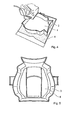
Figur 1 zeigt in schematischer Weise den Prozess des Befüllens eines Füllkragens zur Herstellung eines Vorläufermaterials gemäß der vorliegenden Erfindung. -
Figuren 2 und4 zeigen schematisch in einer perspektivischen Darstellung den befüllten Füllkragen zur Herstellung des Vorläufermaterials gemäß der vorliegenden Erfindung. -
Figur 3 zeigt ebenfalls schematisch in einer Schnittdarstellung den befüllten Füllkragen zur Herstellung des Vorläufermaterials gemäß der vorliegenden Erfindung. -
Figur 5 zeigt schematisch in einer Schnittdarstellung den Füllkragen in einem Zustand, in dem ein Einlegematerial in den Füllkragen eingelegt ist und bevor das Polstermaterial eingefüllt ist. -
Figur 1 zeigt, wie zur Herstellung eines Polsterelements ein Materialgemenge 1 (nachfolgend auch als Polstermaterial 1 bezeichnet) in ein vorformgebendes Werkzeug 2 (nachfolgend auch als Füllkragen 2 bzw. als Vorformling-Werkzeug 2 bezeichnet) gestreut wird. Dies erfolgt erfindungsgemäß insbesondere mittels eines inFigur 1 schematisch angedeuteten Roboters. Als Füllkragen 2 bzw. als Vorformling-Werkzeug 2 denkbar ist jedes Gefäß, das die Kontur des Halbzeugs - insbesondere die laterale Kontur des Halbzeugs - vorformen kann. Das vorformgebende Werkzeug 2 ist gemäß einer bevorzugten Ausführungsform unten offen und befindet sich, wie inFigur 2 zu sehen ist, auf einer plattenförmigen Unterlage 3 wie z.B. einer Lochblechplatte oder einem konturierten Lochblech. Zwischen der plattenförmigen Unterlage 3 und vorformgebendem Werkzeug 2 befindet sich eine Trägermateriallage 4, insbesondere ein Vlies 4 bzw. ein Recyclingvlies, welche insbesondere lediglich gemäß eines Rechteckzuschnitts vorliegt, d.h. nicht der Kontur des Füllkragens 2 angepasst ist. Bei der Trägermateriallage 4 kann es sich beispielsweise um ein Baumwollvlies oder ein anderes Vlies unterschiedlicher Materialzusammensetzung handeln. Entscheidend ist, dass die Trägermateriallage 4 für gasförmige Fluide durchlässig ist, da bei dem Streuprozess an der plattenförmigen Unterlage 3 ein Unterdruck 6 angelegt wird, damit das Materialgemenge 1 nicht wieder zurückprallt. Die Trägermateriallage 4 muss aber undurchlässig für das Materialgemenge 1 selbst sein, damit dieses in dem vorformgebenden Werkzeug 2 verbleibt. Die Trägermateriallage 4 hat den weiteren Vorteil, beim späteren Trimmen der Polsterauflagen als Bezugshilfe zu wirken und so einen nachgeschalteten Prozess zu vereinfachen. - In
Fig. 3 ist zu sehen, wie erwärmtes Fluid, wie beispielsweise Luft, das Materialgemenge 1 durchströmt (7a und 7b) und dabei trocknet. Der Trocknungsvorgang kann auch zu einem späteren Prozessschritt erfolgen. Hat das Materialgemenge 1 seinen notwendigen Füllstand erreicht, wird das vorformgebende Werkzeug 2 entfernt. Die Außenkontur des Halbzeugs wird durch allgemein bekannte Beschneidetechniken, wie beispielsweise Stanzen, Wasserstrahlen oder Laserschneiden, dem späteren Polsterteil entsprechend erzeugt. Hierbei wird vorteilhaft im wesentlichen lediglich die Trägermateriallage 4 beschnitten (weil die Kontur des Polstermaterials 1 bereits durch den Füllkragen definiert ist. Das Halbzeug, umfassend das Materialgemenge 1 bzw. das Polstermaterial 1 und die Trägermateriallage 4, wird im Folgenden auch als Vorläufermaterial bezeichnet. - Das beschnittene Halbzeug (bzw. das Vorläufermaterial) wird positionsgenau in das formgebende Werkzeug (bzw. Formwerkzeug) platziert, so dass keine Überstände in Dichtkanten oder Klappen auftreten. Die Positioniergenauigkeit wird erreicht durch Positionierelemente wie z.B. Stifte im Werkzeug. Die Werkzeuge können auf Transport- und Handhabungseinrichtungen wie Rundtische oder Bänder gelagert, beziehungsweise transportiert werden. Die Formung des Vorläufermaterials (bzw. des Halbzeugs) zum geformten Polsterelement (welches in der Regel noch mit einem Bezug versehen werden muss) erfolgt durch Schließen des Formwerkzeugs. Vor und/oder nach der Formung des Vorläufermaterials wird das Vorläufermaterial und insbesondere das Materialgemenge 1 weiter getrocknet.
- Nach dem Entformen (aus dem Formwerkzeug) hat die Polsterauflage (bzw. das Polsterelement) ihre Endkontur erreicht und ein nachgeschalteter mechanischer Eingriff ist nicht mehr vonnöten.
- Nachfolgend werden Varianten des erfindungsgemäßen Verfahrens beschrieben:
- Gemäß einer ersten Variante des erfindungsgemäßen Verfahrens ist es vorgesehen, dass vor dem Befüllen des Füllkragens 2 mit dem Polstermaterial 1 ein Einlegematerial 8 in den Füllkragen 2 eingelegt wird. Dies ist in
Figur 5 dargestellt. Auf das Einlegematerial 8 wird das Polstermaterial 1 (bzw. das Materialgemenge 1) gemäß dem zuvor beschriebenen Herstellungsverfahren aufgestreut. Das Einlegematerial 8 befindet sich zwischen dem Polstermaterial 1 und der Trägermateriallage 4 und ist Teil des Vorläufermaterials, wenn dieses in das Formwerkzeug eingelegt wird. Auf diese Weise ist es mit dem erfindungsgemäßen Verfahren möglich, in Richtung senkrecht auf die Oberfläche des fertigen Polsterelements unterschiedliche Härten des Polsterelements bzw. eine progressiv zunehmende Härte zu erzielen. - Gemäß einer weiteren Variante des erfindungsgemäßen Verfahrens ist es vorgesehen, dass kein oder nur ein rechteckförmiger (d.h. nicht der lateralen Kontur des Formwerkzeugs angepasster) Füllkragen 2 verwendet wird und dass die laterale Formgebung bzw. Definition der Kontur des Vorläufermaterials vor dem Einbringen in das Formwerkzeug dadurch realisiert wird, dass durch die komplette Dicke des Vorläufermaterials (d.h. insbesondere auch durch das auf die Trägermateriallage 4 aufgestreute Polstermaterial 1) ein Schneidvorgang erfolgt, beispielsweise mittels Wasserstrahlschneiden. Diese Verfahrensvariante hat den Nachteil, dass hinsichtlich des Polstermaterials 1 Verschnitt erzeugt wird, der durch die Benutzung eines konturangepassten Füllkragens vermieden werden kann.
-
- 1
- Polstermaterial / Materialgemenge
- 2
- Füllkragen / Vorformling-Werkzeug / vorformgebendes Werkzeug
- 3
- plattenförmige Unterlage
- 4
- Trägermateriallage / Vlies
- 5
- Streukopf
- 6
- Unterdruck
- 7a, 7b
- erwärmtes Fluid / Luft
- 8
- Einlegematerial
Claims (5)
- Verfahren zur Herstellung eines Sitzpolsterelements zur Verwendung in einem Kraftfahrzeug, wobei ein Vorläufermaterial In einem Formwerkzeug geformt wird, dadurch gekennzeichnet, dass das Vorläufermaterial an die zu erreichende Endform des Sitzpolsterelements angepasst wird, bevor das Formwerkzeug vollständig geschlossen wird, wobei das Vorläufermaterial zumindest teilweise in einen Füllkragen (2) eingefüllt wird, bevor das Vorläufermaterial in das Formwerkzeug eingeführt wird, wobei das Vorläufermaterial wenigstens eine Trägermateriallage (4) und ein Polstermaterial (1) aufweist, wobei die Trägermateriallage (4) nach dem Einfüllen des Polstermaterials (1) in den Füllkragen (2) und vor dem Einführen des Vorläufermaterials in das Formwerkzeug zugeschnitten wird, wobei vor der Befüllung des Füllkragens (2) mit dem Polstermaterial (1) ein Einlegematerial (8) in den Füllkragen (2) eingelegt wird.
- Verfahren nach Anspruch 1, dadurch gekennzeichnet, dass die Trägermateriallage (4) mittels eines Laserschneidprozesses oder mittels eines Wasserstrahlschneidprozesses zugeschnitten wird.
- Verfahren nach einem der vorhergehenden Ansprüche, dadurch gekennzeichnet, dass die Form des Füllkragens (2) im Wesentlichen der Abwicklung der Form des Formwerkzeugs entspricht.
- Verfahren nach einem der vorhergehenden Ansprüche, dadurch gekennzeichnet, dass die Trägermateriallage (4) insbesondere als ein Vlies, insbesondere als ein Recyclingvlies vorgesehen ist.
- Verfahren nach einem der vorhergehenden Ansprüche, dadurch gekennzeichnet, dass das Polstermaterial (1) als ein Gemisch aus Fasern und einem Bindemittel, insbesondere ein Latex enthaltendes Bindemittel, vorgesehen ist.
Priority Applications (1)
| Application Number | Priority Date | Filing Date | Title |
|---|---|---|---|
| PL09006296T PL2116357T3 (pl) | 2008-05-09 | 2009-05-08 | Sposób wytwarzania wyściółki tapicerskiej |
Applications Claiming Priority (2)
| Application Number | Priority Date | Filing Date | Title |
|---|---|---|---|
| DE102008023089 | 2008-05-09 | ||
| DE102008035621.2A DE102008035621B4 (de) | 2008-05-09 | 2008-07-31 | Verfahren zur Herstellung eines Polsterelements, und derart hergestellte Polsterelemente |
Publications (2)
| Publication Number | Publication Date |
|---|---|
| EP2116357A1 EP2116357A1 (de) | 2009-11-11 |
| EP2116357B1 true EP2116357B1 (de) | 2012-09-12 |
Family
ID=40885932
Family Applications (1)
| Application Number | Title | Priority Date | Filing Date |
|---|---|---|---|
| EP09006296A Active EP2116357B1 (de) | 2008-05-09 | 2009-05-08 | Verfahren zur Herstellung einer Polsterauflage |
Country Status (3)
| Country | Link |
|---|---|
| EP (1) | EP2116357B1 (de) |
| DE (1) | DE102008035621B4 (de) |
| PL (1) | PL2116357T3 (de) |
Families Citing this family (4)
| Publication number | Priority date | Publication date | Assignee | Title |
|---|---|---|---|---|
| DE102008006742A1 (de) * | 2008-01-30 | 2009-08-06 | Airbus Deutschland Gmbh | Luftfahrzeug-Brennstoffzellensystem |
| DE102010005994B4 (de) | 2010-01-27 | 2022-07-28 | Tianjin Shenglong Fibre Co., Ltd. | Verfahren zur Hestellung eines Hybrid-Polsterelements, insbesondere eines Sitz- und Lehnenpolsterelements zur Verwendung in einem Kraftfahrzeug, ein Polsterelement und ein Fahrzeugsitz mit einem Polsterelement. |
| US9144943B2 (en) * | 2012-02-15 | 2015-09-29 | Olbrich Gmbh | Fiber mold filling system and method |
| DE102016224251B4 (de) | 2016-12-06 | 2019-02-28 | Adidas Ag | Wärmedämmende Struktur |
Family Cites Families (4)
| Publication number | Priority date | Publication date | Assignee | Title |
|---|---|---|---|---|
| DE1165474B (de) * | 1954-04-13 | 1964-03-12 | Artur Geyer | Verfahren und Vorrichtung zum Herstellen von Kunststeinen |
| US4923731A (en) * | 1988-12-27 | 1990-05-08 | Ppg Industries, Inc. | Novel preform screens and preform product |
| DE102005015473B3 (de) * | 2005-04-04 | 2006-11-16 | Johnson Controls Gmbh | Polsterelement und Herstellverfahren |
| DE102005035108A1 (de) * | 2005-07-27 | 2006-07-27 | Krauss-Maffei Kunststofftechnik Gmbh | Kunststoffverarbeitende Maschine und Verfahren zum Betrieb einer solchen Maschine |
-
2008
- 2008-07-31 DE DE102008035621.2A patent/DE102008035621B4/de not_active Expired - Fee Related
-
2009
- 2009-05-08 EP EP09006296A patent/EP2116357B1/de active Active
- 2009-05-08 PL PL09006296T patent/PL2116357T3/pl unknown
Also Published As
| Publication number | Publication date |
|---|---|
| DE102008035621A1 (de) | 2009-11-26 |
| PL2116357T3 (pl) | 2013-06-28 |
| EP2116357A1 (de) | 2009-11-11 |
| DE102008035621B4 (de) | 2014-11-20 |
Similar Documents
| Publication | Publication Date | Title |
|---|---|---|
| EP2528773B1 (de) | Verfahren zur herstellung eines hybrid-polsterelements, insbesondere eines sitz- und lehnenpolsterelements zur verwendung in einem kraftfahrzeug, ein polsterelement und ein fahrzeugsitz mit einem polsterelement | |
| DE3101804C2 (de) | Polstermaterial und Verfahren zu dessen Herstellung | |
| EP2406102B1 (de) | Fahrzeugsitzpolster | |
| DE102008035621B4 (de) | Verfahren zur Herstellung eines Polsterelements, und derart hergestellte Polsterelemente | |
| DE102014213373A1 (de) | Polsterelement | |
| DE102016117425A1 (de) | Verfahren zum Herstellen eines geformten Produktes mit gesteuerter Dichte und damit hergestelltes geformtes Produkt | |
| DE102010006668A1 (de) | Polsterung und Verfahren zur Herstellung einer Polsterung | |
| WO2009129964A2 (de) | Verfahren zur herstellung eines polsterelements, insbesondere ein sitzpolsterelement zur verwendung in einem kraftfahrzeug, und polsterelement | |
| DE69316827T2 (de) | Herstellverfahren für Polstermaterial | |
| EP1868843B1 (de) | Polsterelement und herstellverfahren | |
| DE102010012212A1 (de) | Sitzpolster mit Luftkanal | |
| DE102016217189A1 (de) | Ausstattungsteil und Verfahren zur Herstellung eines Ausstattungsteiles | |
| DE102012104316A1 (de) | Verfahren zur Fertigung eines Bauteils | |
| EP3463974B1 (de) | Sitzlehnenverkleidung und verfahren zu deren herstellung | |
| DE102010062707A1 (de) | Verfahren zum Herstellen von Polsterteilen, insbesondere für Fahrzeugsitze, Polsterteil und Werkzeug | |
| DE10338215B4 (de) | Polsterteil, insbesondere Ausstattungsteil für den Innenraum eines Kraftfahrzeugs, Verfahren zu seiner Herstellung und Sitz | |
| EP3265299B1 (de) | Bauteil und verfahren zu dessen herstellung | |
| DE102013209270B4 (de) | Vorrichtung zum Einspannen einer Faseranordnung | |
| DE102014106621A1 (de) | Verfahren zur Herstellung eines Kraftfahrzeugbauteils sowie Kraftfahrzeugbauteil | |
| DE102012106012A1 (de) | Weichpolster für ein Fahrzeug und Herstellungsverfahren davon | |
| DE102012013597A1 (de) | Sitzanlage, insbesondere Fahrzeugsitz, für einen Kraftwagen | |
| DE102008051978A1 (de) | Innenraumteil für ein Fahrzeug | |
| DE102010017714A1 (de) | Blasformsitz und Verfahren zu dessen Herstellung | |
| DE102014224741A1 (de) | Verfahren zur Herstellung von Vorformlingen sowie eines Faserverbundbauteils und Faserverbundbauteil | |
| DE3009885B1 (de) | Verfahren zur Herstellung von Polsterauflagen,Form zur Durchfuehrung des Verfahrens und mit dem Verfahren hergestellte Polsterauflage |
Legal Events
| Date | Code | Title | Description |
|---|---|---|---|
| PUAI | Public reference made under article 153(3) epc to a published international application that has entered the european phase |
Free format text: ORIGINAL CODE: 0009012 |
|
| AK | Designated contracting states |
Kind code of ref document: A1 Designated state(s): AT BE BG CH CY CZ DE DK EE ES FI FR GB GR HR HU IE IS IT LI LT LU LV MC MK MT NL NO PL PT RO SE SI SK TR |
|
| 17P | Request for examination filed |
Effective date: 20100511 |
|
| 17Q | First examination report despatched |
Effective date: 20100614 |
|
| RTI1 | Title (correction) |
Free format text: METHOD FOR CREATING A PADDED OVERLAY |
|
| GRAP | Despatch of communication of intention to grant a patent |
Free format text: ORIGINAL CODE: EPIDOSNIGR1 |
|
| GRAS | Grant fee paid |
Free format text: ORIGINAL CODE: EPIDOSNIGR3 |
|
| GRAA | (expected) grant |
Free format text: ORIGINAL CODE: 0009210 |
|
| AK | Designated contracting states |
Kind code of ref document: B1 Designated state(s): AT BE BG CH CY CZ DE DK EE ES FI FR GB GR HR HU IE IS IT LI LT LU LV MC MK MT NL NO PL PT RO SE SI SK TR |
|
| REG | Reference to a national code |
Ref country code: GB Ref legal event code: FG4D Free format text: NOT ENGLISH |
|
| REG | Reference to a national code |
Ref country code: CH Ref legal event code: EP |
|
| REG | Reference to a national code |
Ref country code: AT Ref legal event code: REF Ref document number: 574844 Country of ref document: AT Kind code of ref document: T Effective date: 20120915 |
|
| REG | Reference to a national code |
Ref country code: IE Ref legal event code: FG4D Free format text: LANGUAGE OF EP DOCUMENT: GERMAN |
|
| REG | Reference to a national code |
Ref country code: DE Ref legal event code: R082 Ref document number: 502009004685 Country of ref document: DE Representative=s name: KUTZENBERGER & WOLFF, DE Ref country code: DE Ref legal event code: R082 Ref document number: 502009004685 Country of ref document: DE Representative=s name: KUTZENBERGER WOLFF & PARTNER, DE Ref country code: DE Ref legal event code: R082 Ref document number: 502009004685 Country of ref document: DE Representative=s name: KUTZENBERGER WOLFF & PARTNER PATENTANWALTSPART, DE |
|
| REG | Reference to a national code |
Ref country code: DE Ref legal event code: R096 Ref document number: 502009004685 Country of ref document: DE Effective date: 20121108 |
|
| PG25 | Lapsed in a contracting state [announced via postgrant information from national office to epo] |
Ref country code: LT Free format text: LAPSE BECAUSE OF FAILURE TO SUBMIT A TRANSLATION OF THE DESCRIPTION OR TO PAY THE FEE WITHIN THE PRESCRIBED TIME-LIMIT Effective date: 20120912 Ref country code: FI Free format text: LAPSE BECAUSE OF FAILURE TO SUBMIT A TRANSLATION OF THE DESCRIPTION OR TO PAY THE FEE WITHIN THE PRESCRIBED TIME-LIMIT Effective date: 20120912 Ref country code: HR Free format text: LAPSE BECAUSE OF FAILURE TO SUBMIT A TRANSLATION OF THE DESCRIPTION OR TO PAY THE FEE WITHIN THE PRESCRIBED TIME-LIMIT Effective date: 20120912 Ref country code: NO Free format text: LAPSE BECAUSE OF FAILURE TO SUBMIT A TRANSLATION OF THE DESCRIPTION OR TO PAY THE FEE WITHIN THE PRESCRIBED TIME-LIMIT Effective date: 20121212 |
|
| REG | Reference to a national code |
Ref country code: NL Ref legal event code: VDEP Effective date: 20120912 |
|
| REG | Reference to a national code |
Ref country code: LT Ref legal event code: MG4D Effective date: 20120912 |
|
| PG25 | Lapsed in a contracting state [announced via postgrant information from national office to epo] |
Ref country code: LV Free format text: LAPSE BECAUSE OF FAILURE TO SUBMIT A TRANSLATION OF THE DESCRIPTION OR TO PAY THE FEE WITHIN THE PRESCRIBED TIME-LIMIT Effective date: 20120912 Ref country code: SE Free format text: LAPSE BECAUSE OF FAILURE TO SUBMIT A TRANSLATION OF THE DESCRIPTION OR TO PAY THE FEE WITHIN THE PRESCRIBED TIME-LIMIT Effective date: 20120912 Ref country code: SI Free format text: LAPSE BECAUSE OF FAILURE TO SUBMIT A TRANSLATION OF THE DESCRIPTION OR TO PAY THE FEE WITHIN THE PRESCRIBED TIME-LIMIT Effective date: 20120912 Ref country code: GR Free format text: LAPSE BECAUSE OF FAILURE TO SUBMIT A TRANSLATION OF THE DESCRIPTION OR TO PAY THE FEE WITHIN THE PRESCRIBED TIME-LIMIT Effective date: 20121213 |
|
| REG | Reference to a national code |
Ref country code: SK Ref legal event code: T3 Ref document number: E 12989 Country of ref document: SK |
|
| PG25 | Lapsed in a contracting state [announced via postgrant information from national office to epo] |
Ref country code: IS Free format text: LAPSE BECAUSE OF FAILURE TO SUBMIT A TRANSLATION OF THE DESCRIPTION OR TO PAY THE FEE WITHIN THE PRESCRIBED TIME-LIMIT Effective date: 20130112 Ref country code: ES Free format text: LAPSE BECAUSE OF FAILURE TO SUBMIT A TRANSLATION OF THE DESCRIPTION OR TO PAY THE FEE WITHIN THE PRESCRIBED TIME-LIMIT Effective date: 20121223 Ref country code: RO Free format text: LAPSE BECAUSE OF FAILURE TO SUBMIT A TRANSLATION OF THE DESCRIPTION OR TO PAY THE FEE WITHIN THE PRESCRIBED TIME-LIMIT Effective date: 20120912 Ref country code: NL Free format text: LAPSE BECAUSE OF FAILURE TO SUBMIT A TRANSLATION OF THE DESCRIPTION OR TO PAY THE FEE WITHIN THE PRESCRIBED TIME-LIMIT Effective date: 20120912 Ref country code: EE Free format text: LAPSE BECAUSE OF FAILURE TO SUBMIT A TRANSLATION OF THE DESCRIPTION OR TO PAY THE FEE WITHIN THE PRESCRIBED TIME-LIMIT Effective date: 20120912 |
|
| PG25 | Lapsed in a contracting state [announced via postgrant information from national office to epo] |
Ref country code: PT Free format text: LAPSE BECAUSE OF FAILURE TO SUBMIT A TRANSLATION OF THE DESCRIPTION OR TO PAY THE FEE WITHIN THE PRESCRIBED TIME-LIMIT Effective date: 20130114 |
|
| REG | Reference to a national code |
Ref country code: PL Ref legal event code: T3 |
|
| PLBE | No opposition filed within time limit |
Free format text: ORIGINAL CODE: 0009261 |
|
| STAA | Information on the status of an ep patent application or granted ep patent |
Free format text: STATUS: NO OPPOSITION FILED WITHIN TIME LIMIT |
|
| PG25 | Lapsed in a contracting state [announced via postgrant information from national office to epo] |
Ref country code: DK Free format text: LAPSE BECAUSE OF FAILURE TO SUBMIT A TRANSLATION OF THE DESCRIPTION OR TO PAY THE FEE WITHIN THE PRESCRIBED TIME-LIMIT Effective date: 20120912 Ref country code: BG Free format text: LAPSE BECAUSE OF FAILURE TO SUBMIT A TRANSLATION OF THE DESCRIPTION OR TO PAY THE FEE WITHIN THE PRESCRIBED TIME-LIMIT Effective date: 20121212 |
|
| PGFP | Annual fee paid to national office [announced via postgrant information from national office to epo] |
Ref country code: IE Payment date: 20130426 Year of fee payment: 5 |
|
| 26N | No opposition filed |
Effective date: 20130613 |
|
| PG25 | Lapsed in a contracting state [announced via postgrant information from national office to epo] |
Ref country code: IT Free format text: LAPSE BECAUSE OF FAILURE TO SUBMIT A TRANSLATION OF THE DESCRIPTION OR TO PAY THE FEE WITHIN THE PRESCRIBED TIME-LIMIT Effective date: 20120912 |
|
| REG | Reference to a national code |
Ref country code: DE Ref legal event code: R097 Ref document number: 502009004685 Country of ref document: DE Effective date: 20130613 |
|
| BERE | Be: lapsed |
Owner name: JOHNSON CONTROLS G.M.B.H. Effective date: 20130531 Owner name: ALBA TOOLING & ENGINEERING G.M.B.H. Effective date: 20130531 |
|
| PG25 | Lapsed in a contracting state [announced via postgrant information from national office to epo] |
Ref country code: MC Free format text: LAPSE BECAUSE OF FAILURE TO SUBMIT A TRANSLATION OF THE DESCRIPTION OR TO PAY THE FEE WITHIN THE PRESCRIBED TIME-LIMIT Effective date: 20120912 |
|
| REG | Reference to a national code |
Ref country code: CH Ref legal event code: PL |
|
| GBPC | Gb: european patent ceased through non-payment of renewal fee |
Effective date: 20130508 |
|
| PG25 | Lapsed in a contracting state [announced via postgrant information from national office to epo] |
Ref country code: LI Free format text: LAPSE BECAUSE OF NON-PAYMENT OF DUE FEES Effective date: 20130531 Ref country code: CH Free format text: LAPSE BECAUSE OF NON-PAYMENT OF DUE FEES Effective date: 20130531 |
|
| PG25 | Lapsed in a contracting state [announced via postgrant information from national office to epo] |
Ref country code: BE Free format text: LAPSE BECAUSE OF NON-PAYMENT OF DUE FEES Effective date: 20130531 |
|
| PG25 | Lapsed in a contracting state [announced via postgrant information from national office to epo] |
Ref country code: GB Free format text: LAPSE BECAUSE OF NON-PAYMENT OF DUE FEES Effective date: 20130508 |
|
| REG | Reference to a national code |
Ref country code: DE Ref legal event code: R082 Ref document number: 502009004685 Country of ref document: DE Representative=s name: KUTZENBERGER WOLFF & PARTNER PATENTANWALTSPART, DE |
|
| REG | Reference to a national code |
Ref country code: DE Ref legal event code: R082 Ref document number: 502009004685 Country of ref document: DE Representative=s name: KUTZENBERGER WOLFF & PARTNER PATENTANWALTSPART, DE Effective date: 20140602 Ref country code: DE Ref legal event code: R081 Ref document number: 502009004685 Country of ref document: DE Owner name: ALBA TOOLING & ENGINEERING GMBH, DE Free format text: FORMER OWNER: ALBA TOOLING & ENGINEERING GMBH, JOHNSON CONTROLS GMBH, , DE Effective date: 20140602 Ref country code: DE Ref legal event code: R081 Ref document number: 502009004685 Country of ref document: DE Owner name: JOHNSON CONTROLS GMBH, DE Free format text: FORMER OWNER: ALBA TOOLING & ENGINEERING GMBH, JOHNSON CONTROLS GMBH, , DE Effective date: 20140602 Ref country code: DE Ref legal event code: R082 Ref document number: 502009004685 Country of ref document: DE Representative=s name: KUTZENBERGER WOLFF & PARTNER PATENTANWALTSPART, DE Effective date: 20121105 Ref country code: DE Ref legal event code: R081 Ref document number: 502009004685 Country of ref document: DE Owner name: JOHNSON CONTROLS GMBH, DE Free format text: FORMER OWNERS: ALBA TOOLING & ENGINEERING GMBH, 32278 KIRCHLENGERN, DE; JOHNSON CONTROLS GMBH, 51399 BURSCHEID, DE Effective date: 20140602 Ref country code: DE Ref legal event code: R081 Ref document number: 502009004685 Country of ref document: DE Owner name: ALBA TOOLING & ENGINEERING GMBH, DE Free format text: FORMER OWNERS: ALBA TOOLING & ENGINEERING GMBH, 32278 KIRCHLENGERN, DE; JOHNSON CONTROLS GMBH, 51399 BURSCHEID, DE Effective date: 20140602 |
|
| REG | Reference to a national code |
Ref country code: SK Ref legal event code: TE4A Ref document number: E 12989 Country of ref document: SK Owner name: ALBA TOOLING & ENGINEERING GMBH, BISSENDORF, DE Effective date: 20141111 Ref country code: SK Ref legal event code: TE4A Ref document number: E 12989 Country of ref document: SK Owner name: JOHNSON CONTROLS GMBH, BURSCHEID, DE Effective date: 20141111 |
|
| REG | Reference to a national code |
Ref country code: IE Ref legal event code: MM4A |
|
| PG25 | Lapsed in a contracting state [announced via postgrant information from national office to epo] |
Ref country code: MT Free format text: LAPSE BECAUSE OF FAILURE TO SUBMIT A TRANSLATION OF THE DESCRIPTION OR TO PAY THE FEE WITHIN THE PRESCRIBED TIME-LIMIT Effective date: 20120912 |
|
| PG25 | Lapsed in a contracting state [announced via postgrant information from national office to epo] |
Ref country code: IE Free format text: LAPSE BECAUSE OF NON-PAYMENT OF DUE FEES Effective date: 20140508 |
|
| PG25 | Lapsed in a contracting state [announced via postgrant information from national office to epo] |
Ref country code: CY Free format text: LAPSE BECAUSE OF FAILURE TO SUBMIT A TRANSLATION OF THE DESCRIPTION OR TO PAY THE FEE WITHIN THE PRESCRIBED TIME-LIMIT Effective date: 20120912 Ref country code: TR Free format text: LAPSE BECAUSE OF FAILURE TO SUBMIT A TRANSLATION OF THE DESCRIPTION OR TO PAY THE FEE WITHIN THE PRESCRIBED TIME-LIMIT Effective date: 20120912 |
|
| REG | Reference to a national code |
Ref country code: AT Ref legal event code: MM01 Ref document number: 574844 Country of ref document: AT Kind code of ref document: T Effective date: 20140508 |
|
| PG25 | Lapsed in a contracting state [announced via postgrant information from national office to epo] |
Ref country code: HU Free format text: LAPSE BECAUSE OF FAILURE TO SUBMIT A TRANSLATION OF THE DESCRIPTION OR TO PAY THE FEE WITHIN THE PRESCRIBED TIME-LIMIT; INVALID AB INITIO Effective date: 20090508 Ref country code: MK Free format text: LAPSE BECAUSE OF FAILURE TO SUBMIT A TRANSLATION OF THE DESCRIPTION OR TO PAY THE FEE WITHIN THE PRESCRIBED TIME-LIMIT Effective date: 20120912 Ref country code: LU Free format text: LAPSE BECAUSE OF NON-PAYMENT OF DUE FEES Effective date: 20130508 |
|
| PGFP | Annual fee paid to national office [announced via postgrant information from national office to epo] |
Ref country code: DE Payment date: 20150531 Year of fee payment: 7 |
|
| PG25 | Lapsed in a contracting state [announced via postgrant information from national office to epo] |
Ref country code: AT Free format text: LAPSE BECAUSE OF NON-PAYMENT OF DUE FEES Effective date: 20140508 |
|
| REG | Reference to a national code |
Ref country code: FR Ref legal event code: PLFP Year of fee payment: 8 |
|
| REG | Reference to a national code |
Ref country code: DE Ref legal event code: R119 Ref document number: 502009004685 Country of ref document: DE |
|
| PG25 | Lapsed in a contracting state [announced via postgrant information from national office to epo] |
Ref country code: DE Free format text: LAPSE BECAUSE OF NON-PAYMENT OF DUE FEES Effective date: 20161201 |
|
| REG | Reference to a national code |
Ref country code: FR Ref legal event code: PLFP Year of fee payment: 9 |
|
| REG | Reference to a national code |
Ref country code: FR Ref legal event code: PLFP Year of fee payment: 10 |
|
| REG | Reference to a national code |
Ref country code: SK Ref legal event code: PC4A Ref document number: E 12989 Country of ref document: SK Owner name: ALBA TOOLING & ENGINEERING GMBH, BISSENDORF, DE Free format text: FORMER OWNER: JOHNSON CONTROLS GMBH, BURSCHEID, DE; ALBA TOOLING & ENGINEERING GMBH, BISSENDORF, DE Effective date: 20210120 Ref country code: SK Ref legal event code: PC4A Ref document number: E 12989 Country of ref document: SK Owner name: ADIENT LUXEMBOURG HOLDING S.A R.L., LUXEMBOURG, LU Free format text: FORMER OWNER: JOHNSON CONTROLS GMBH, BURSCHEID, DE; ALBA TOOLING & ENGINEERING GMBH, BISSENDORF, DE Effective date: 20210120 |
|
| PGFP | Annual fee paid to national office [announced via postgrant information from national office to epo] |
Ref country code: SK Payment date: 20220419 Year of fee payment: 14 Ref country code: FR Payment date: 20220525 Year of fee payment: 14 Ref country code: CZ Payment date: 20220425 Year of fee payment: 14 |
|
| PGFP | Annual fee paid to national office [announced via postgrant information from national office to epo] |
Ref country code: PL Payment date: 20220420 Year of fee payment: 14 |
|
| REG | Reference to a national code |
Ref country code: SK Ref legal event code: MM4A Ref document number: E 12989 Country of ref document: SK Effective date: 20230508 |
|
| PG25 | Lapsed in a contracting state [announced via postgrant information from national office to epo] |
Ref country code: SK Free format text: LAPSE BECAUSE OF NON-PAYMENT OF DUE FEES Effective date: 20230508 |
|
| PG25 | Lapsed in a contracting state [announced via postgrant information from national office to epo] |
Ref country code: SK Free format text: LAPSE BECAUSE OF NON-PAYMENT OF DUE FEES Effective date: 20230508 Ref country code: CZ Free format text: LAPSE BECAUSE OF NON-PAYMENT OF DUE FEES Effective date: 20230508 |
|
| PG25 | Lapsed in a contracting state [announced via postgrant information from national office to epo] |
Ref country code: FR Free format text: LAPSE BECAUSE OF NON-PAYMENT OF DUE FEES Effective date: 20230531 |