EP2116322A1 - Workpiece to be spot-welded - Google Patents
Workpiece to be spot-welded Download PDFInfo
- Publication number
- EP2116322A1 EP2116322A1 EP08738579A EP08738579A EP2116322A1 EP 2116322 A1 EP2116322 A1 EP 2116322A1 EP 08738579 A EP08738579 A EP 08738579A EP 08738579 A EP08738579 A EP 08738579A EP 2116322 A1 EP2116322 A1 EP 2116322A1
- Authority
- EP
- European Patent Office
- Prior art keywords
- edge
- spot welding
- work piece
- lateral flange
- work
- Prior art date
- Legal status (The legal status is an assumption and is not a legal conclusion. Google has not performed a legal analysis and makes no representation as to the accuracy of the status listed.)
- Granted
Links
- 238000003466 welding Methods 0.000 claims abstract description 58
- 238000000034 method Methods 0.000 description 7
- 239000003351 stiffener Substances 0.000 description 5
- 230000004075 alteration Effects 0.000 description 1
- 230000000694 effects Effects 0.000 description 1
- 238000004519 manufacturing process Methods 0.000 description 1
- 239000000463 material Substances 0.000 description 1
- 238000012986 modification Methods 0.000 description 1
- 230000004048 modification Effects 0.000 description 1
- 238000003908 quality control method Methods 0.000 description 1
- 230000035945 sensitivity Effects 0.000 description 1
- 238000009966 trimming Methods 0.000 description 1
Images
Classifications
-
- B—PERFORMING OPERATIONS; TRANSPORTING
- B62—LAND VEHICLES FOR TRAVELLING OTHERWISE THAN ON RAILS
- B62D—MOTOR VEHICLES; TRAILERS
- B62D25/00—Superstructure or monocoque structure sub-units; Parts or details thereof not otherwise provided for
- B62D25/04—Door pillars ; windshield pillars
-
- B—PERFORMING OPERATIONS; TRANSPORTING
- B23—MACHINE TOOLS; METAL-WORKING NOT OTHERWISE PROVIDED FOR
- B23K—SOLDERING OR UNSOLDERING; WELDING; CLADDING OR PLATING BY SOLDERING OR WELDING; CUTTING BY APPLYING HEAT LOCALLY, e.g. FLAME CUTTING; WORKING BY LASER BEAM
- B23K11/00—Resistance welding; Severing by resistance heating
- B23K11/10—Spot welding; Stitch welding
- B23K11/11—Spot welding
-
- B—PERFORMING OPERATIONS; TRANSPORTING
- B23—MACHINE TOOLS; METAL-WORKING NOT OTHERWISE PROVIDED FOR
- B23K—SOLDERING OR UNSOLDERING; WELDING; CLADDING OR PLATING BY SOLDERING OR WELDING; CUTTING BY APPLYING HEAT LOCALLY, e.g. FLAME CUTTING; WORKING BY LASER BEAM
- B23K33/00—Specially-profiled edge portions of workpieces for making soldering or welding connections; Filling the seams formed thereby
- B23K33/004—Filling of continuous seams
- B23K33/008—Filling of continuous seams for automotive applications
-
- B—PERFORMING OPERATIONS; TRANSPORTING
- B23—MACHINE TOOLS; METAL-WORKING NOT OTHERWISE PROVIDED FOR
- B23K—SOLDERING OR UNSOLDERING; WELDING; CLADDING OR PLATING BY SOLDERING OR WELDING; CUTTING BY APPLYING HEAT LOCALLY, e.g. FLAME CUTTING; WORKING BY LASER BEAM
- B23K2101/00—Articles made by soldering, welding or cutting
- B23K2101/006—Vehicles
Definitions
- the present invention relates to a plurality of work pieces that are joined together by spot welding.
- a vehicle body such as an automotive body typically includes a center pillar located between a front door and a rear door on each side of the vehicle body as an important part of a vehicle body framework.
- a center pillar typically includes a pair of work pieces located on the outboard side and inboard side of the vehicle body in a mutually opposing relationship and joined to each other by spot welding the side edges thereof so as to define a rectangular closed cross section.
- at least one of the work pieces is provided with flanges for spot welding along either side edge thereof (see Japanese patent laid open publication No. 06-278466 ).
- the spot welding may be performed from the inboard side or outboard side depending on the facilities of the assembly plant and the particular welding procedure, and there may be some difficulty in ensuring the quality of the welding work depending on from which side the welding is performed.
- a primary object of the present invention is to provide work pieces provided with marks for determining locations for spot welding which are easy to recognize, and simplifies the task of managing the quality of welding work.
- such a task can be accomplished by providing work pieces that are joined together by spot welding, comprising: a first work piece provided with a lateral flange including an edge; a second work piece including a part laid over the lateral flange of the first work piece and spot welded to the lateral flange at a plurality of locations; wherein the edge of the lateral flange is provided with a wavy shape including a plurality of peaks and dips in an alternating manner, and the spot welded locations are located in the peaks of the edge of the lateral flange.
- the present invention may further include an opening trim which includes a slot defined by a pair of mutually opposing walls for receiving the edge of the lateral flange of the first work piece and the part of the second work piece spot welded to the flange and a pair of mutually opposing clamping lips formed on the mutually opposing walls, the clamping pieces being spaced from a bottom of the slot by a distance greater than that between an edge of the peaks of the lateral flanges and/or the spot welded part of the work piece and the dips of the lateral flange.
- highly recognizable marks for indicating locations for spot welding can be formed by the wavy shape of the lateral flange of the first work piece.
- the wavy shape may be of such dimensions as to permit required recognizability without reducing the mechanical strength of the welded parts or the affected work piece.
- each peak may include a flattened straight section having a certain length corresponding to a designated area for spot welding.
- each dip may be defined by an arcuate segment having a concave side directed outward, and the straight section of each peak may be smoothly connected to the adjacent dip via an arcuate segment having a convex side directed outward.
- dents or recesses for marking spot welded locations are formed on a side of the second work piece facing away from the first work piece, the locations for spot welding can be recognized not only from the side of the first work piece but also from the side of the second work piece.
- the present invention is particularly advantageous, not limitatively, when spot welding the parts of a monocoque vehicle body surrounding door openings.
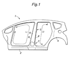
- the illustrated vehicle body frame 1 comprises a side sill 2 extending in a lower part of each side part thereof in a fore-and-aft direction.
- the illustrated vehicle body frame 1 is that of a four-door passenger car, and includes a center pillar 3 located between a pair of openings for a front door and a rear door.
- the center pillar 3 comprises a pair of work pieces or a center pillar outer 5 forming a part of an outer side panel 4 and a center pillar inner 6 placed onto the center pillar outer 5 from the inboard side thereof.
- a center pillar stiffener 7 is interposed between the center pillar outer 5 and center pillar inner 6.
- the spot welding for the inner and outer frame members surrounding the door openings including the parts for the center pillar is performed along a part of the edge of the front door opening indicated by L1 in Figure 1 and along a part of the edge of the rear door opening indicated by L2 in Figure 1 .
- the center pillar inner 6 is generally spaced away from the stiffener 7, but is provided with a flange 8 which is bent to the outboard side with respect to the remaining part of the center pillar inner 6 along the edges indicated by L1 and L2 in Figure 1 .
- the flange 8 is closely placed onto the stiffener 7 which is in turn closely placed onto the center pillar outer 5.
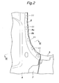
- the flange 8 is provided with an outer edge given with a wavy profile as best illustrated in Figure 2 while the outer edge of the center pillar outer 5 is substantially linear or slightly curved as required by the designed outer profile of the finished center pillar.
- the outer edge of each peak of the wavy edge profile of the flange 8 substantially coincides with the outer edge of the center pillar outer 5.
- Each dip of the wavy edge profile of the flange 8 is set back by a distance from the peaks 8a of the wavy edge profile of the flange 8 as illustrated in Figure 3 .
- the edge of the stiffener 7 is substantially conformal with the wave edge of the flange 8 of the center pillar inner 6.
- the edge of the stiffener 7 may be substantially linear or slightly curved as required, and coincide with the outer edge of each peak of the wavy edge profile of the flange 8 or the outer edge of each dip of the wavy edge profile of the flange 8.
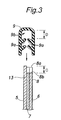
- the edge of this assembly is fitted with an opening trim 9 ( Figure 3 ) in a work process following the spot welding process, and the opening trim 9 includes a slot 9b defined by a pair of mutually opposing walls for receiving the edge of this assembly and a pair of mutually opposing clamping lips 9a formed on the mutually opposing walls.
- the distance C between the edge of this assembly (which may be an outer edge of the peaks 8a of the flange 8 of the center pillar inner 6 or the outer edge of the center pillar outer 5) and the dips 8b is selected such that a clamping lip 9a of the opening trim 9 is resiliently pushed against the surface of the center pillar inner 6 when the opening trim 9 is attached.
- the clamping lips 9a are spaced from a bottom of the slot by a distance D greater than the distance C between the edge of the assembly and the dips 8b of the lateral flange 8 (D>C).
- D the distance between the edge of the assembly and the dips 8b of the lateral flange 8
- the peaks 8a of the lateral flange 8 are offset from the edge of the center pillar outer 5 in a somewhat exaggerated manner, and this offset may be extremely small in reality. These two edges may substantially coincide with each other. Therefore, the distance C substantially corresponds to the depth of the dips 8b. If the distance C is excessive, the clamping lips 9a may fall into a dip 8b when the opening trim 9 is attached to the edge of the flange 8.
- the opposing clamping lips 9a designed to clamp the center pillar outer 5 and center pillar inner 6 from both sides may not provide an adequate clamping force to hold the opening trim 9 in place.
- the clamping lips 9a are prevented from falling into a dip 8b when the opening trim 9 is attached to the flange 8, and the mutually opposing clamping lips 9a are enabled to clamp the center pillar outer 5 and center pillar inner 6 without fail so that the opening trim 9 is prevented from being dislodged from the flange 8.
- the flange 8 of the center pillar inner 6 is thus given with a wavy formed edge as discussed above, and the peaks 8a provide a guide for selecting the locations 11 for performing the spot welding as illustrated in Figure 2 .
- the welder is enabled to identify the locations for spot welding both clearly and precisely.
- the flange 8 is provided for the convenience of spot welding, and is therefore not required to have a uniform width in parts where spot welding is not performed to ensure a required mechanical strength as long as the parts to which the opening trims 9a are attached are given with a necessary thickness.
- the wavy form of the edge of the flange 8 satisfies such requirements, and the removal of the material of the center pillar inner 6 to form the dips 8b of the wavy form contributes to the reduction in the weight of the center pillar inner 6.
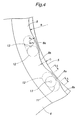
- Each location for spot welding (which is selected according to a particular spot welding plan) is selected at a midpoint between two adjacent peaks 8a, but is designated as an area 12 for spot welding by considering a tolerance S for a positional error along the length of the flange 8.
- a track-shaped area defined by a pair of mutually circumscribing circles (having a radius of Rs) arranged along the length of the flange 8 and centered around the spot welding location defines an area 12 for spot welding.
- Each peak 8a of the wavy shaped edge may be flattened and extend by a length corresponding to the length of the straight section of the track shape as illustrated in Figure 2 .
- Each dip 8b may be formed by an arcuate segment (having a curvature radius of R) having a desired depth as measured from the straight sections.
- the transitional segment extending between each straight section and the adjacent dip 8b may be defined by a circle having a radius of Rc concentric to the corresponding one of the aforementioned circles having the radius Rs, Rc being given as a sum of the radius Rs and a desired margin of tolerance.
- the radius of each basic circle Rs may be 5 mm
- the radius Rc for an added margin may be 6 (5+1) mm.
- each dip 8b includes an arcuate segment having a concave side directed outward, and the straight section of each peak is smoothly connected to the adjacent dip via an arcuate segment having a convex side directed outward.
- the edge is given with a smooth profile so that cracks owing to stress concentration are prevented from developing at the time of a vehicle crash.
- the locations for spot welding can be readily determined from the locations of the peaks 8a and the welding work can be performed by visually noting the locations of the peaks 8a so that the welding work can be simplified.
- each peak 8a is defined so as to correspond to a spot welding area having a certain expanse and provide a certain positional tolerance, it can be readily determined that each spot welded locations is selected to design, and the quality control of the spot welding part can be simplified.
- the wave shaped edge is formed in such manner that the edge of the flange includes peaks 8a and dips 8b in an alternating manner as seen in the plane of the flange, it can be easily formed by trimming the corresponding edge of the center pillar inner 6 in a corresponding manner during the stamping process. Therefore, providing markings for spot welding work does not involve additional manufacturing step or an increase in the amount of work.
- a plurality of dents 13 are provided on the outboard side of the center pillar outer 5.
- the welding may have to be performed from both the outboard and inboard sides.
- the wave shape of the edge of the flange of the center pillar inner may be used as a marking when welding from the inboard side, and the dent 13 may be used as a marking when welding from the outboard side.
- the interior of a vehicle body is dimmer than the outside because the lighting is more readily available for work outside of the vehicle body. Therefore, the dents 13 may be adequate as a marking for the spot welding work performed from outside the vehicle body.
- the wavy shaped edge provides a more readily discernible marking for the spot welding work which is often required to be performed under a dimmer condition.
- the foregoing embodiment was directed to a center pillar 3, but the present invention is by no means limited to a center pillar but may also be applied to any work pieces that are spot welded as long as at least one of the work pieces is provided with a flange and the two work pieces are spot welded to each other via the flange.
Landscapes
- Engineering & Computer Science (AREA)
- Mechanical Engineering (AREA)
- Chemical & Material Sciences (AREA)
- Combustion & Propulsion (AREA)
- Transportation (AREA)
- Body Structure For Vehicles (AREA)
- Vehicle Interior And Exterior Ornaments, Soundproofing, And Insulation (AREA)
- Laser Beam Processing (AREA)
Abstract
Description
- The present invention relates to a plurality of work pieces that are joined together by spot welding.
- A vehicle body such as an automotive body typically includes a center pillar located between a front door and a rear door on each side of the vehicle body as an important part of a vehicle body framework. A center pillar typically includes a pair of work pieces located on the outboard side and inboard side of the vehicle body in a mutually opposing relationship and joined to each other by spot welding the side edges thereof so as to define a rectangular closed cross section. To facilitate the spot welding process, at least one of the work pieces is provided with flanges for spot welding along either side edge thereof (see Japanese patent laid open publication No.
06-278466 - When spot welding such a flange of a work piece to the other work piece which may be provided with a corresponding flange, it is necessary to perform spot welding at a plurality of locations arranged along the length of the flange, and the locations of spot welding are required to be specifically determined so that a desired welding strength may be achieved. Conventionally, to guide a welder to perform spot welding at such selected locations with a required accuracy, it was practiced to form dents or recesses that serve as markers for a welder at pre-selected locations during the preceding stamping process.
- However, if such dents or recesses are excessively deep and/or extensive, they may reduce the mechanical strength of such parts, and are therefore typically so small that a welder may have some difficulty in recognizing them. Also, the spot welding may be performed from the inboard side or outboard side depending on the facilities of the assembly plant and the particular welding procedure, and there may be some difficulty in ensuring the quality of the welding work depending on from which side the welding is performed.
- In view of such problems of the prior art, a primary object of the present invention is to provide work pieces provided with marks for determining locations for spot welding which are easy to recognize, and simplifies the task of managing the quality of welding work.
- According to the present invention, such a task can be accomplished by providing work pieces that are joined together by spot welding, comprising: a first work piece provided with a lateral flange including an edge; a second work piece including a part laid over the lateral flange of the first work piece and spot welded to the lateral flange at a plurality of locations; wherein the edge of the lateral flange is provided with a wavy shape including a plurality of peaks and dips in an alternating manner, and the spot welded locations are located in the peaks of the edge of the lateral flange.
- The present invention may further include an opening trim which includes a slot defined by a pair of mutually opposing walls for receiving the edge of the lateral flange of the first work piece and the part of the second work piece spot welded to the flange and a pair of mutually opposing clamping lips formed on the mutually opposing walls, the clamping pieces being spaced from a bottom of the slot by a distance greater than that between an edge of the peaks of the lateral flanges and/or the spot welded part of the work piece and the dips of the lateral flange.
- Thus, according to the present invention, highly recognizable marks for indicating locations for spot welding can be formed by the wavy shape of the lateral flange of the first work piece. As opposed to dents or recesses which cannot be deep enough to be readily recognizable owing to the limit in the thickness of the work piece, the wavy shape may be of such dimensions as to permit required recognizability without reducing the mechanical strength of the welded parts or the affected work piece. To provide a margin for the positional precision of each location for welding, each peak may include a flattened straight section having a certain length corresponding to a designated area for spot welding.
- For avoiding any ill effect from a notch sensitivity that could be caused by the wavy shape of the edge of the lateral flange, each dip may be defined by an arcuate segment having a concave side directed outward, and the straight section of each peak may be smoothly connected to the adjacent dip via an arcuate segment having a convex side directed outward.
- If dents or recesses for marking spot welded locations are formed on a side of the second work piece facing away from the first work piece, the locations for spot welding can be recognized not only from the side of the first work piece but also from the side of the second work piece.
- The present invention is particularly advantageous, not limitatively, when spot welding the parts of a monocoque vehicle body surrounding door openings.
- Now the present invention is described in the following with reference to the appended drawings, in which:
-
Figure 1 is an inboard side view of a vehicle body frame top which the present invention is applied; -
Figure 2 is an enlarged fragmentary perspective view of the part indicated by arrow II inFigure 1 ; -
Figure 3 is a sectional view taken along line III-III ofFigure 2 to show how an opening trim can be fitted on the edge of the welded panel assembly; and -
Figure 4 is an enlarged fragmentary view of a part ofFigure 2 . - Referring to
Figure 1 , the illustrated vehicle body frame 1 comprises aside sill 2 extending in a lower part of each side part thereof in a fore-and-aft direction. The illustrated vehicle body frame 1 is that of a four-door passenger car, and includes acenter pillar 3 located between a pair of openings for a front door and a rear door. - As shown in
Figure 2 , thecenter pillar 3 comprises a pair of work pieces or a center pillar outer 5 forming a part of an outer side panel 4 and a center pillar inner 6 placed onto the center pillar outer 5 from the inboard side thereof. As shown inFigure 3 , acenter pillar stiffener 7 is interposed between the center pillar outer 5 and center pillar inner 6. - In the illustrated embodiment, the spot welding for the inner and outer frame members surrounding the door openings including the parts for the center pillar is performed along a part of the edge of the front door opening indicated by L1 in
Figure 1 and along a part of the edge of the rear door opening indicated by L2 inFigure 1 . - The center pillar inner 6 is generally spaced away from the
stiffener 7, but is provided with aflange 8 which is bent to the outboard side with respect to the remaining part of the center pillar inner 6 along the edges indicated by L1 and L2 inFigure 1 . Theflange 8 is closely placed onto thestiffener 7 which is in turn closely placed onto the center pillar outer 5. - The
flange 8 is provided with an outer edge given with a wavy profile as best illustrated inFigure 2 while the outer edge of the center pillar outer 5 is substantially linear or slightly curved as required by the designed outer profile of the finished center pillar. The outer edge of each peak of the wavy edge profile of theflange 8 substantially coincides with the outer edge of the center pillar outer 5. Each dip of the wavy edge profile of theflange 8 is set back by a distance from thepeaks 8a of the wavy edge profile of theflange 8 as illustrated inFigure 3 . In the illustrated embodiment, the edge of thestiffener 7 is substantially conformal with the wave edge of theflange 8 of the center pillar inner 6. However, the edge of thestiffener 7 may be substantially linear or slightly curved as required, and coincide with the outer edge of each peak of the wavy edge profile of theflange 8 or the outer edge of each dip of the wavy edge profile of theflange 8. - The edge of this assembly is fitted with an opening trim 9 (
Figure 3 ) in a work process following the spot welding process, and theopening trim 9 includes aslot 9b defined by a pair of mutually opposing walls for receiving the edge of this assembly and a pair of mutually opposingclamping lips 9a formed on the mutually opposing walls. The distance C between the edge of this assembly (which may be an outer edge of thepeaks 8a of theflange 8 of the center pillar inner 6 or the outer edge of the center pillar outer 5) and thedips 8b is selected such that aclamping lip 9a of theopening trim 9 is resiliently pushed against the surface of the center pillar inner 6 when theopening trim 9 is attached. In other words, theclamping lips 9a are spaced from a bottom of the slot by a distance D greater than the distance C between the edge of the assembly and thedips 8b of the lateral flange 8 (D>C). InFigure 2 , thepeaks 8a of thelateral flange 8 are offset from the edge of the center pillar outer 5 in a somewhat exaggerated manner, and this offset may be extremely small in reality. These two edges may substantially coincide with each other. Therefore, the distance C substantially corresponds to the depth of thedips 8b. If the distance C is excessive, theclamping lips 9a may fall into adip 8b when theopening trim 9 is attached to the edge of theflange 8. If it is the case, theopposing clamping lips 9a designed to clamp the center pillar outer 5 and center pillar inner 6 from both sides may not provide an adequate clamping force to hold theopening trim 9 in place. By selecting the distance C at an appropriate level as discussed above, theclamping lips 9a are prevented from falling into adip 8b when theopening trim 9 is attached to theflange 8, and the mutually opposingclamping lips 9a are enabled to clamp the center pillar outer 5 and center pillar inner 6 without fail so that theopening trim 9 is prevented from being dislodged from theflange 8. - The
flange 8 of the center pillar inner 6 is thus given with a wavy formed edge as discussed above, and thepeaks 8a provide a guide for selecting thelocations 11 for performing the spot welding as illustrated inFigure 2 . As opposed to the small dents used in the conventional arrangement, the welder is enabled to identify the locations for spot welding both clearly and precisely. Theflange 8 is provided for the convenience of spot welding, and is therefore not required to have a uniform width in parts where spot welding is not performed to ensure a required mechanical strength as long as the parts to which theopening trims 9a are attached are given with a necessary thickness. The wavy form of the edge of theflange 8 satisfies such requirements, and the removal of the material of the center pillar inner 6 to form thedips 8b of the wavy form contributes to the reduction in the weight of the center pillar inner 6. - A specific example of the wavy form is given in
Figure 4 . Each location for spot welding (which is selected according to a particular spot welding plan) is selected at a midpoint between twoadjacent peaks 8a, but is designated as anarea 12 for spot welding by considering a tolerance S for a positional error along the length of theflange 8. In the example illustrated inFigure 4 , for each givenlocation 11 for spot welding, a track-shaped area defined by a pair of mutually circumscribing circles (having a radius of Rs) arranged along the length of theflange 8 and centered around the spot welding location defines anarea 12 for spot welding. - Each
peak 8a of the wavy shaped edge may be flattened and extend by a length corresponding to the length of the straight section of the track shape as illustrated inFigure 2 . Eachdip 8b may be formed by an arcuate segment (having a curvature radius of R) having a desired depth as measured from the straight sections. The transitional segment extending between each straight section and theadjacent dip 8b may be defined by a circle having a radius of Rc concentric to the corresponding one of the aforementioned circles having the radius Rs, Rc being given as a sum of the radius Rs and a desired margin of tolerance. For instance, the radius of each basic circle Rs may be 5 mm, and the radius Rc for an added margin may be 6 (5+1) mm. In other words, eachdip 8b includes an arcuate segment having a concave side directed outward, and the straight section of each peak is smoothly connected to the adjacent dip via an arcuate segment having a convex side directed outward. - By thus forming the
peaks 8a and dips 8b of the wavy shape of the edge of theflange 8 with moderate arcuate segments (having the radii of curvature of Rs and Rc) in addition to the straight sections, the edge is given with a smooth profile so that cracks owing to stress concentration are prevented from developing at the time of a vehicle crash. The locations for spot welding can be readily determined from the locations of thepeaks 8a and the welding work can be performed by visually noting the locations of thepeaks 8a so that the welding work can be simplified. Also, because eachpeak 8a is defined so as to correspond to a spot welding area having a certain expanse and provide a certain positional tolerance, it can be readily determined that each spot welded locations is selected to design, and the quality control of the spot welding part can be simplified. - Because the wave shaped edge is formed in such manner that the edge of the flange includes
peaks 8a and dips 8b in an alternating manner as seen in the plane of the flange, it can be easily formed by trimming the corresponding edge of the center pillar inner 6 in a corresponding manner during the stamping process. Therefore, providing markings for spot welding work does not involve additional manufacturing step or an increase in the amount of work. - In the illustrated embodiment, as shown in
Figure 3 , a plurality ofdents 13 are provided on the outboard side of the center pillar outer 5. Depending on the facility of the assembly plant and/or the procedure of the welding work, the welding may have to be performed from both the outboard and inboard sides. The wave shape of the edge of the flange of the center pillar inner may be used as a marking when welding from the inboard side, and thedent 13 may be used as a marking when welding from the outboard side. - Typically, the interior of a vehicle body is dimmer than the outside because the lighting is more readily available for work outside of the vehicle body. Therefore, the
dents 13 may be adequate as a marking for the spot welding work performed from outside the vehicle body. The wavy shaped edge provides a more readily discernible marking for the spot welding work which is often required to be performed under a dimmer condition. - The foregoing embodiment was directed to a
center pillar 3, but the present invention is by no means limited to a center pillar but may also be applied to any work pieces that are spot welded as long as at least one of the work pieces is provided with a flange and the two work pieces are spot welded to each other via the flange. - Although the present invention has been described in terms of preferred embodiments thereof, it is obvious to a person skilled in the art that various alterations and modifications are possible without departing from the scope of the present invention which is set forth in the appended claims.
- The contents of the original Japanese patent application on which the Paris Convention priority claim is made for the present application as well as the contents of the prior art references mentioned in the present application are incorporated in this application by reference.
Claims (7)
- Work pieces that are joined together by spot welding, comprising:a first work piece provided with a lateral flange including an edge;a second work piece including a part laid over the lateral flange of the first work piece and spot welded to the lateral flange at a plurality of locations;wherein the edge of the lateral flange is provided with a wavy shape including a plurality of peaks and dips in an alternating manner, and the spot welded locations are located in the peaks of the edge of the lateral flange.
- The work pieces that are joined together by spot welding according to claim 1, wherein each peak includes a flattened straight section having a certain length corresponding to a designated area for spot welding.
- The work pieces that are joined together by spot welding according to claim 1, wherein each dip includes an arcuate segment having a concave side directed outward.
- The work pieces that are joined together by spot welding according to claim 2, wherein each dip includes an arcuate segment having a concave side directed outward, and the straight section of each peak is smoothly connected to the adjacent dip via an arcuate segment having a convex side directed outward.
- The work pieces that are joined together by spot welding according to claim 1, wherein dents or recesses for marking spot welded locations are formed on a side of the second work piece facing away from the first work piece.
- The work pieces that are joined together by spot welding according to claim 1, wherein the work pieces include a center pillar outer and a center pillar inner.
- A combination of a pair of work pieces that are joined together by spot welding and an opening trim:
wherein the work pieces include a first work piece provided with a lateral flange including an edge; a second work piece including a part laid over the lateral flange of the first work piece and spot welded to the lateral flange at a plurality of locations; the edge of the lateral flange being provided with a wavy shape including a plurality of peaks and dips in an alternating manner, and spot welded locations are located in the peaks of the edge of the lateral flange; and
wherein the opening trim includes a slot defined by a pair of mutually opposing walls for receiving the edge of the lateral flange of the first work piece and the part of the second work piece spot welded to the flange and a pair of mutually opposing clamping lips formed on the mutually opposing walls, the clamping pieces being spaced from a bottom of the slot by a distance greater than that between an edge of the peaks of the lateral flanges and/or the spot welded part of the work piece and the dips of the lateral flange.
Applications Claiming Priority (2)
| Application Number | Priority Date | Filing Date | Title |
|---|---|---|---|
| JP2007167262 | 2007-06-26 | ||
| PCT/JP2008/000973 WO2009001498A1 (en) | 2007-06-26 | 2008-04-14 | Workpiece to be spot-welded |
Publications (3)
| Publication Number | Publication Date |
|---|---|
| EP2116322A1 true EP2116322A1 (en) | 2009-11-11 |
| EP2116322A4 EP2116322A4 (en) | 2010-03-03 |
| EP2116322B1 EP2116322B1 (en) | 2012-01-25 |
Family
ID=40185326
Family Applications (1)
| Application Number | Title | Priority Date | Filing Date |
|---|---|---|---|
| EP08738579A Not-in-force EP2116322B1 (en) | 2007-06-26 | 2008-04-14 | Workpiece to be spot-welded |
Country Status (5)
| Country | Link |
|---|---|
| EP (1) | EP2116322B1 (en) |
| JP (1) | JP5161214B2 (en) |
| CN (1) | CN101626863B (en) |
| AT (1) | ATE542628T1 (en) |
| WO (1) | WO2009001498A1 (en) |
Cited By (3)
| Publication number | Priority date | Publication date | Assignee | Title |
|---|---|---|---|---|
| US20160082495A1 (en) * | 2013-05-13 | 2016-03-24 | Nippon Steel & Sumitomo Metal Corporation | Blank, forming plate, press formed article manufacturing method, and press formed article |
| US20180037754A1 (en) * | 2014-12-23 | 2018-02-08 | 3M Innovative Properties Company | Tie Layers Prepared from Particle-Containing Waterborne Suspensions |
| US11344969B2 (en) | 2017-11-01 | 2022-05-31 | Nippon Steel Corporation | Overlapping bonded structure |
Families Citing this family (3)
| Publication number | Priority date | Publication date | Assignee | Title |
|---|---|---|---|---|
| FR2940954B1 (en) * | 2009-01-14 | 2017-10-20 | Peugeot Citroen Automobiles Sa | FOLDING CONSISTING OF THE SUPERPOSITION OF TWO SHEETS, INTENDED TO SUPPORT A SEAL AND MOTOR VEHICLE WHICH THE FUND HAS SUCH A SHEET |
| JP6598529B2 (en) * | 2015-06-25 | 2019-10-30 | スズキ株式会社 | Joint body and vehicle front pillar assembly having the joint body |
| JP6935307B2 (en) * | 2017-11-21 | 2021-09-15 | 豊田鉄工株式会社 | Vehicle reinforcements and vehicle center pillars |
Family Cites Families (4)
| Publication number | Priority date | Publication date | Assignee | Title |
|---|---|---|---|---|
| JPS5960050U (en) * | 1982-10-15 | 1984-04-19 | 三菱自動車工業株式会社 | Opening trim device |
| JPH06278466A (en) | 1993-03-29 | 1994-10-04 | Nissan Shatai Co Ltd | Side car body structure of slide door car |
| JP3196477B2 (en) * | 1993-11-04 | 2001-08-06 | トヨタ自動車株式会社 | Structure of car door opening |
| US7857377B2 (en) * | 2006-10-09 | 2010-12-28 | Ford Global Technologies, Llc | Tubular B-pillar to stamped rocker joint and method of assembling the same |
-
2008
- 2008-04-14 CN CN2008800072093A patent/CN101626863B/en not_active Expired - Fee Related
- 2008-04-14 AT AT08738579T patent/ATE542628T1/en active
- 2008-04-14 EP EP08738579A patent/EP2116322B1/en not_active Not-in-force
- 2008-04-14 JP JP2009520286A patent/JP5161214B2/en not_active Expired - Fee Related
- 2008-04-14 WO PCT/JP2008/000973 patent/WO2009001498A1/en not_active Ceased
Non-Patent Citations (2)
| Title |
|---|
| No further relevant documents disclosed * |
| See also references of WO2009001498A1 * |
Cited By (4)
| Publication number | Priority date | Publication date | Assignee | Title |
|---|---|---|---|---|
| US20160082495A1 (en) * | 2013-05-13 | 2016-03-24 | Nippon Steel & Sumitomo Metal Corporation | Blank, forming plate, press formed article manufacturing method, and press formed article |
| US20180037754A1 (en) * | 2014-12-23 | 2018-02-08 | 3M Innovative Properties Company | Tie Layers Prepared from Particle-Containing Waterborne Suspensions |
| US10723894B2 (en) * | 2014-12-23 | 2020-07-28 | 3M Innovative Properties Company | Tie layers prepared from particle-containing waterborne suspensions |
| US11344969B2 (en) | 2017-11-01 | 2022-05-31 | Nippon Steel Corporation | Overlapping bonded structure |
Also Published As
| Publication number | Publication date |
|---|---|
| CN101626863A (en) | 2010-01-13 |
| ATE542628T1 (en) | 2012-02-15 |
| WO2009001498A1 (en) | 2008-12-31 |
| EP2116322B1 (en) | 2012-01-25 |
| JPWO2009001498A1 (en) | 2010-08-26 |
| CN101626863B (en) | 2013-06-12 |
| JP5161214B2 (en) | 2013-03-13 |
| EP2116322A4 (en) | 2010-03-03 |
Similar Documents
| Publication | Publication Date | Title |
|---|---|---|
| EP2116322B1 (en) | Workpiece to be spot-welded | |
| US11660652B2 (en) | Multi-tubular beam for a vehicle | |
| US5237734A (en) | Method of interlocking hemmed together panels | |
| EP1752250A1 (en) | Laser welding method, laser welded joint, outer panel, and structure for rolling stock | |
| US7959212B2 (en) | Welded blank for vehicle door panel | |
| EP3604006A1 (en) | A structure of a door for a motor-vehicle | |
| US6957848B2 (en) | Engineered welded blank | |
| JP7040329B2 (en) | Cross member | |
| EP3858510A1 (en) | Press formed component and method for manufacturing same | |
| DE202019102613U1 (en) | Roof frame bracket assembly | |
| DE10158961A1 (en) | Car roof outer part comprises steel or aluminum sheet with edge strip bent back and foamed leaving cable or antenna guide channel and flanged to coachwork. | |
| CN115158471A (en) | Automobile rear seat belt retractor mounting structure | |
| EP0995514B1 (en) | Panel assembly of hemmed panels and its method of manufacture | |
| DE4445942C1 (en) | Method of manufacturing car body parts | |
| CN214451460U (en) | Instrument board assembly subassembly and car | |
| DE102013210008A1 (en) | Vehicle door reinforcing carrier for use in door assembly of motor car, has variable cross-section extending in longitudinal direction of carrier with respect to vehicle, and circular cross-section formed in support bend | |
| US20190100250A1 (en) | Vehicle body side part structure | |
| JPH0246462Y2 (en) | ||
| JP6824775B2 (en) | Aperture frame for railcars | |
| JPH09175456A (en) | Vehicle body assembly accuracy confirmation method and vehicle body structure | |
| JP3147771B2 (en) | Car center pillar structure | |
| EP1764286A1 (en) | Vehicle chassis pillar | |
| JP2022084115A (en) | Vehicle component | |
| JP2001270479A (en) | Body assembly equipment | |
| JPH03136978A (en) | Roof side rail structure |
Legal Events
| Date | Code | Title | Description |
|---|---|---|---|
| PUAI | Public reference made under article 153(3) epc to a published international application that has entered the european phase |
Free format text: ORIGINAL CODE: 0009012 |
|
| 17P | Request for examination filed |
Effective date: 20090812 |
|
| AK | Designated contracting states |
Kind code of ref document: A1 Designated state(s): AT BE BG CH CY CZ DE DK EE ES FI FR GB GR HR HU IE IS IT LI LT LU LV MC MT NL NO PL PT RO SE SI SK TR |
|
| A4 | Supplementary search report drawn up and despatched |
Effective date: 20100202 |
|
| RIC1 | Information provided on ipc code assigned before grant |
Ipc: B23K 11/00 20060101ALI20100127BHEP Ipc: B23K 11/11 20060101AFI20090122BHEP Ipc: B23K 33/00 20060101ALI20100127BHEP Ipc: B62D 25/04 20060101ALI20100127BHEP |
|
| 17Q | First examination report despatched |
Effective date: 20100315 |
|
| DAX | Request for extension of the european patent (deleted) | ||
| GRAP | Despatch of communication of intention to grant a patent |
Free format text: ORIGINAL CODE: EPIDOSNIGR1 |
|
| RIC1 | Information provided on ipc code assigned before grant |
Ipc: B23K 33/00 20060101ALI20110726BHEP Ipc: B23K 11/11 20060101AFI20110726BHEP Ipc: B62D 25/04 20060101ALI20110726BHEP Ipc: B23K 11/00 20060101ALI20110726BHEP |
|
| GRAS | Grant fee paid |
Free format text: ORIGINAL CODE: EPIDOSNIGR3 |
|
| GRAA | (expected) grant |
Free format text: ORIGINAL CODE: 0009210 |
|
| AK | Designated contracting states |
Kind code of ref document: B1 Designated state(s): AT BE BG CH CY CZ DE DK EE ES FI FR GB GR HR HU IE IS IT LI LT LU LV MC MT NL NO PL PT RO SE SI SK TR |
|
| REG | Reference to a national code |
Ref country code: GB Ref legal event code: FG4D |
|
| REG | Reference to a national code |
Ref country code: CH Ref legal event code: EP |
|
| REG | Reference to a national code |
Ref country code: AT Ref legal event code: REF Ref document number: 542628 Country of ref document: AT Kind code of ref document: T Effective date: 20120215 |
|
| REG | Reference to a national code |
Ref country code: IE Ref legal event code: FG4D |
|
| REG | Reference to a national code |
Ref country code: DE Ref legal event code: R096 Ref document number: 602008012896 Country of ref document: DE Effective date: 20120322 |
|
| REG | Reference to a national code |
Ref country code: NL Ref legal event code: VDEP Effective date: 20120125 |
|
| LTIE | Lt: invalidation of european patent or patent extension |
Effective date: 20120125 |
|
| PG25 | Lapsed in a contracting state [announced via postgrant information from national office to epo] |
Ref country code: HR Free format text: LAPSE BECAUSE OF FAILURE TO SUBMIT A TRANSLATION OF THE DESCRIPTION OR TO PAY THE FEE WITHIN THE PRESCRIBED TIME-LIMIT Effective date: 20120125 Ref country code: BE Free format text: LAPSE BECAUSE OF FAILURE TO SUBMIT A TRANSLATION OF THE DESCRIPTION OR TO PAY THE FEE WITHIN THE PRESCRIBED TIME-LIMIT Effective date: 20120125 Ref country code: NL Free format text: LAPSE BECAUSE OF FAILURE TO SUBMIT A TRANSLATION OF THE DESCRIPTION OR TO PAY THE FEE WITHIN THE PRESCRIBED TIME-LIMIT Effective date: 20120125 Ref country code: NO Free format text: LAPSE BECAUSE OF FAILURE TO SUBMIT A TRANSLATION OF THE DESCRIPTION OR TO PAY THE FEE WITHIN THE PRESCRIBED TIME-LIMIT Effective date: 20120425 Ref country code: BG Free format text: LAPSE BECAUSE OF FAILURE TO SUBMIT A TRANSLATION OF THE DESCRIPTION OR TO PAY THE FEE WITHIN THE PRESCRIBED TIME-LIMIT Effective date: 20120425 Ref country code: LT Free format text: LAPSE BECAUSE OF FAILURE TO SUBMIT A TRANSLATION OF THE DESCRIPTION OR TO PAY THE FEE WITHIN THE PRESCRIBED TIME-LIMIT Effective date: 20120125 Ref country code: IS Free format text: LAPSE BECAUSE OF FAILURE TO SUBMIT A TRANSLATION OF THE DESCRIPTION OR TO PAY THE FEE WITHIN THE PRESCRIBED TIME-LIMIT Effective date: 20120525 |
|
| PG25 | Lapsed in a contracting state [announced via postgrant information from national office to epo] |
Ref country code: LV Free format text: LAPSE BECAUSE OF FAILURE TO SUBMIT A TRANSLATION OF THE DESCRIPTION OR TO PAY THE FEE WITHIN THE PRESCRIBED TIME-LIMIT Effective date: 20120125 Ref country code: FI Free format text: LAPSE BECAUSE OF FAILURE TO SUBMIT A TRANSLATION OF THE DESCRIPTION OR TO PAY THE FEE WITHIN THE PRESCRIBED TIME-LIMIT Effective date: 20120125 Ref country code: PT Free format text: LAPSE BECAUSE OF FAILURE TO SUBMIT A TRANSLATION OF THE DESCRIPTION OR TO PAY THE FEE WITHIN THE PRESCRIBED TIME-LIMIT Effective date: 20120525 Ref country code: PL Free format text: LAPSE BECAUSE OF FAILURE TO SUBMIT A TRANSLATION OF THE DESCRIPTION OR TO PAY THE FEE WITHIN THE PRESCRIBED TIME-LIMIT Effective date: 20120125 Ref country code: GR Free format text: LAPSE BECAUSE OF FAILURE TO SUBMIT A TRANSLATION OF THE DESCRIPTION OR TO PAY THE FEE WITHIN THE PRESCRIBED TIME-LIMIT Effective date: 20120426 |
|
| REG | Reference to a national code |
Ref country code: AT Ref legal event code: MK05 Ref document number: 542628 Country of ref document: AT Kind code of ref document: T Effective date: 20120125 |
|
| PG25 | Lapsed in a contracting state [announced via postgrant information from national office to epo] |
Ref country code: CY Free format text: LAPSE BECAUSE OF FAILURE TO SUBMIT A TRANSLATION OF THE DESCRIPTION OR TO PAY THE FEE WITHIN THE PRESCRIBED TIME-LIMIT Effective date: 20120125 |
|
| PG25 | Lapsed in a contracting state [announced via postgrant information from national office to epo] |
Ref country code: SI Free format text: LAPSE BECAUSE OF FAILURE TO SUBMIT A TRANSLATION OF THE DESCRIPTION OR TO PAY THE FEE WITHIN THE PRESCRIBED TIME-LIMIT Effective date: 20120125 Ref country code: CZ Free format text: LAPSE BECAUSE OF FAILURE TO SUBMIT A TRANSLATION OF THE DESCRIPTION OR TO PAY THE FEE WITHIN THE PRESCRIBED TIME-LIMIT Effective date: 20120125 Ref country code: DK Free format text: LAPSE BECAUSE OF FAILURE TO SUBMIT A TRANSLATION OF THE DESCRIPTION OR TO PAY THE FEE WITHIN THE PRESCRIBED TIME-LIMIT Effective date: 20120125 Ref country code: EE Free format text: LAPSE BECAUSE OF FAILURE TO SUBMIT A TRANSLATION OF THE DESCRIPTION OR TO PAY THE FEE WITHIN THE PRESCRIBED TIME-LIMIT Effective date: 20120125 Ref country code: RO Free format text: LAPSE BECAUSE OF FAILURE TO SUBMIT A TRANSLATION OF THE DESCRIPTION OR TO PAY THE FEE WITHIN THE PRESCRIBED TIME-LIMIT Effective date: 20120125 Ref country code: SE Free format text: LAPSE BECAUSE OF FAILURE TO SUBMIT A TRANSLATION OF THE DESCRIPTION OR TO PAY THE FEE WITHIN THE PRESCRIBED TIME-LIMIT Effective date: 20120125 |
|
| PG25 | Lapsed in a contracting state [announced via postgrant information from national office to epo] |
Ref country code: MC Free format text: LAPSE BECAUSE OF NON-PAYMENT OF DUE FEES Effective date: 20120430 Ref country code: SK Free format text: LAPSE BECAUSE OF FAILURE TO SUBMIT A TRANSLATION OF THE DESCRIPTION OR TO PAY THE FEE WITHIN THE PRESCRIBED TIME-LIMIT Effective date: 20120125 Ref country code: IT Free format text: LAPSE BECAUSE OF FAILURE TO SUBMIT A TRANSLATION OF THE DESCRIPTION OR TO PAY THE FEE WITHIN THE PRESCRIBED TIME-LIMIT Effective date: 20120125 |
|
| PLBE | No opposition filed within time limit |
Free format text: ORIGINAL CODE: 0009261 |
|
| REG | Reference to a national code |
Ref country code: CH Ref legal event code: PL |
|
| STAA | Information on the status of an ep patent application or granted ep patent |
Free format text: STATUS: NO OPPOSITION FILED WITHIN TIME LIMIT |
|
| 26N | No opposition filed |
Effective date: 20121026 |
|
| REG | Reference to a national code |
Ref country code: IE Ref legal event code: MM4A |
|
| PG25 | Lapsed in a contracting state [announced via postgrant information from national office to epo] |
Ref country code: LI Free format text: LAPSE BECAUSE OF NON-PAYMENT OF DUE FEES Effective date: 20120430 Ref country code: AT Free format text: LAPSE BECAUSE OF FAILURE TO SUBMIT A TRANSLATION OF THE DESCRIPTION OR TO PAY THE FEE WITHIN THE PRESCRIBED TIME-LIMIT Effective date: 20120125 Ref country code: CH Free format text: LAPSE BECAUSE OF NON-PAYMENT OF DUE FEES Effective date: 20120430 Ref country code: IE Free format text: LAPSE BECAUSE OF NON-PAYMENT OF DUE FEES Effective date: 20120414 |
|
| REG | Reference to a national code |
Ref country code: DE Ref legal event code: R097 Ref document number: 602008012896 Country of ref document: DE Effective date: 20121026 |
|
| PG25 | Lapsed in a contracting state [announced via postgrant information from national office to epo] |
Ref country code: ES Free format text: LAPSE BECAUSE OF FAILURE TO SUBMIT A TRANSLATION OF THE DESCRIPTION OR TO PAY THE FEE WITHIN THE PRESCRIBED TIME-LIMIT Effective date: 20120506 |
|
| PG25 | Lapsed in a contracting state [announced via postgrant information from national office to epo] |
Ref country code: MT Free format text: LAPSE BECAUSE OF FAILURE TO SUBMIT A TRANSLATION OF THE DESCRIPTION OR TO PAY THE FEE WITHIN THE PRESCRIBED TIME-LIMIT Effective date: 20120125 |
|
| PGFP | Annual fee paid to national office [announced via postgrant information from national office to epo] |
Ref country code: GB Payment date: 20130410 Year of fee payment: 6 Ref country code: DE Payment date: 20130508 Year of fee payment: 6 |
|
| PGFP | Annual fee paid to national office [announced via postgrant information from national office to epo] |
Ref country code: FR Payment date: 20130625 Year of fee payment: 6 |
|
| PG25 | Lapsed in a contracting state [announced via postgrant information from national office to epo] |
Ref country code: LU Free format text: LAPSE BECAUSE OF NON-PAYMENT OF DUE FEES Effective date: 20120414 |
|
| PG25 | Lapsed in a contracting state [announced via postgrant information from national office to epo] |
Ref country code: HU Free format text: LAPSE BECAUSE OF FAILURE TO SUBMIT A TRANSLATION OF THE DESCRIPTION OR TO PAY THE FEE WITHIN THE PRESCRIBED TIME-LIMIT Effective date: 20080414 |
|
| REG | Reference to a national code |
Ref country code: DE Ref legal event code: R119 Ref document number: 602008012896 Country of ref document: DE |
|
| GBPC | Gb: european patent ceased through non-payment of renewal fee |
Effective date: 20140414 |
|
| REG | Reference to a national code |
Ref country code: DE Ref legal event code: R119 Ref document number: 602008012896 Country of ref document: DE Effective date: 20141101 |
|
| REG | Reference to a national code |
Ref country code: FR Ref legal event code: ST Effective date: 20141231 |
|
| PG25 | Lapsed in a contracting state [announced via postgrant information from national office to epo] |
Ref country code: GB Free format text: LAPSE BECAUSE OF NON-PAYMENT OF DUE FEES Effective date: 20140414 Ref country code: DE Free format text: LAPSE BECAUSE OF NON-PAYMENT OF DUE FEES Effective date: 20141101 |
|
| PG25 | Lapsed in a contracting state [announced via postgrant information from national office to epo] |
Ref country code: FR Free format text: LAPSE BECAUSE OF NON-PAYMENT OF DUE FEES Effective date: 20140430 |
|
| PG25 | Lapsed in a contracting state [announced via postgrant information from national office to epo] |
Ref country code: TR Free format text: LAPSE BECAUSE OF NON-PAYMENT OF DUE FEES Effective date: 20140414 |