EP2115316B1 - Liquid cooled brake with support columns - Google Patents
Liquid cooled brake with support columns Download PDFInfo
- Publication number
- EP2115316B1 EP2115316B1 EP08714083A EP08714083A EP2115316B1 EP 2115316 B1 EP2115316 B1 EP 2115316B1 EP 08714083 A EP08714083 A EP 08714083A EP 08714083 A EP08714083 A EP 08714083A EP 2115316 B1 EP2115316 B1 EP 2115316B1
- Authority
- EP
- European Patent Office
- Prior art keywords
- brake
- pins
- support column
- plates
- friction plate
- Prior art date
- Legal status (The legal status is an assumption and is not a legal conclusion. Google has not performed a legal analysis and makes no representation as to the accuracy of the status listed.)
- Active
Links
Images


Classifications
-
- F—MECHANICAL ENGINEERING; LIGHTING; HEATING; WEAPONS; BLASTING
- F16—ENGINEERING ELEMENTS AND UNITS; GENERAL MEASURES FOR PRODUCING AND MAINTAINING EFFECTIVE FUNCTIONING OF MACHINES OR INSTALLATIONS; THERMAL INSULATION IN GENERAL
- F16D—COUPLINGS FOR TRANSMITTING ROTATION; CLUTCHES; BRAKES
- F16D65/00—Parts or details
- F16D65/78—Features relating to cooling
- F16D65/84—Features relating to cooling for disc brakes
- F16D65/853—Features relating to cooling for disc brakes with closed cooling system
-
- F—MECHANICAL ENGINEERING; LIGHTING; HEATING; WEAPONS; BLASTING
- F16—ENGINEERING ELEMENTS AND UNITS; GENERAL MEASURES FOR PRODUCING AND MAINTAINING EFFECTIVE FUNCTIONING OF MACHINES OR INSTALLATIONS; THERMAL INSULATION IN GENERAL
- F16D—COUPLINGS FOR TRANSMITTING ROTATION; CLUTCHES; BRAKES
- F16D55/00—Brakes with substantially-radial braking surfaces pressed together in axial direction, e.g. disc brakes
- F16D55/24—Brakes with substantially-radial braking surfaces pressed together in axial direction, e.g. disc brakes with a plurality of axially-movable discs, lamellae, or pads, pressed from one side towards an axially-located member
- F16D55/26—Brakes with substantially-radial braking surfaces pressed together in axial direction, e.g. disc brakes with a plurality of axially-movable discs, lamellae, or pads, pressed from one side towards an axially-located member without self-tightening action
- F16D55/36—Brakes with a plurality of rotating discs all lying side by side
-
- F—MECHANICAL ENGINEERING; LIGHTING; HEATING; WEAPONS; BLASTING
- F16—ENGINEERING ELEMENTS AND UNITS; GENERAL MEASURES FOR PRODUCING AND MAINTAINING EFFECTIVE FUNCTIONING OF MACHINES OR INSTALLATIONS; THERMAL INSULATION IN GENERAL
- F16D—COUPLINGS FOR TRANSMITTING ROTATION; CLUTCHES; BRAKES
- F16D55/00—Brakes with substantially-radial braking surfaces pressed together in axial direction, e.g. disc brakes
- F16D55/24—Brakes with substantially-radial braking surfaces pressed together in axial direction, e.g. disc brakes with a plurality of axially-movable discs, lamellae, or pads, pressed from one side towards an axially-located member
- F16D55/26—Brakes with substantially-radial braking surfaces pressed together in axial direction, e.g. disc brakes with a plurality of axially-movable discs, lamellae, or pads, pressed from one side towards an axially-located member without self-tightening action
- F16D55/36—Brakes with a plurality of rotating discs all lying side by side
- F16D55/40—Brakes with a plurality of rotating discs all lying side by side actuated by a fluid-pressure device arranged in or one the brake
- F16D55/42—Brakes with a plurality of rotating discs all lying side by side actuated by a fluid-pressure device arranged in or one the brake comprising an expansible fluid-filled flexible member coaxial with the brake
-
- F—MECHANICAL ENGINEERING; LIGHTING; HEATING; WEAPONS; BLASTING
- F16—ENGINEERING ELEMENTS AND UNITS; GENERAL MEASURES FOR PRODUCING AND MAINTAINING EFFECTIVE FUNCTIONING OF MACHINES OR INSTALLATIONS; THERMAL INSULATION IN GENERAL
- F16D—COUPLINGS FOR TRANSMITTING ROTATION; CLUTCHES; BRAKES
- F16D65/00—Parts or details
- F16D65/78—Features relating to cooling
- F16D65/84—Features relating to cooling for disc brakes
- F16D65/847—Features relating to cooling for disc brakes with open cooling system, e.g. cooled by air
-
- F—MECHANICAL ENGINEERING; LIGHTING; HEATING; WEAPONS; BLASTING
- F16—ENGINEERING ELEMENTS AND UNITS; GENERAL MEASURES FOR PRODUCING AND MAINTAINING EFFECTIVE FUNCTIONING OF MACHINES OR INSTALLATIONS; THERMAL INSULATION IN GENERAL
- F16D—COUPLINGS FOR TRANSMITTING ROTATION; CLUTCHES; BRAKES
- F16D65/00—Parts or details
- F16D65/78—Features relating to cooling
- F16D2065/784—Features relating to cooling the coolant not being in direct contact with the braking surface
-
- F—MECHANICAL ENGINEERING; LIGHTING; HEATING; WEAPONS; BLASTING
- F16—ENGINEERING ELEMENTS AND UNITS; GENERAL MEASURES FOR PRODUCING AND MAINTAINING EFFECTIVE FUNCTIONING OF MACHINES OR INSTALLATIONS; THERMAL INSULATION IN GENERAL
- F16D—COUPLINGS FOR TRANSMITTING ROTATION; CLUTCHES; BRAKES
- F16D2121/00—Type of actuator operation force
- F16D2121/02—Fluid pressure
-
- F—MECHANICAL ENGINEERING; LIGHTING; HEATING; WEAPONS; BLASTING
- F16—ENGINEERING ELEMENTS AND UNITS; GENERAL MEASURES FOR PRODUCING AND MAINTAINING EFFECTIVE FUNCTIONING OF MACHINES OR INSTALLATIONS; THERMAL INSULATION IN GENERAL
- F16D—COUPLINGS FOR TRANSMITTING ROTATION; CLUTCHES; BRAKES
- F16D2125/00—Components of actuators
- F16D2125/02—Fluid-pressure mechanisms
- F16D2125/14—Fluid-filled flexible members, e.g. enclosed air bladders
Definitions
- This invention relates to liquid cooled brakes and, more particularly, to a liquid cooled brake in which support columns are used to provide a lightweight yet strong supporting housing.
- a conventional liquid cooled disc brake includes a stationary housing disposed about a rotating shaft.
- a plurality of friction plates are coupled to the housing and fixed against rotation relative to the housing, but axially moveable relative to the housing. These friction plates define fluid jackets through which cooling liquids are circulated.
- Another plurality of friction plates are coupled to the shaft for rotation therewith and are axially movable relative to the shaft.
- the plates coupled to the shaft are interleaved with the plates coupled to the housing.
- a brake actuator is disposed at one axial end of the brake and applies a force in an axial direction to bring the plates into contact with one another.
- US 6,029,782 discloses a brake having multiple actuators.
- the brake comprises a torque transmission assembly centered about a longitudinal axis, a hub that is rotatable about the axis, and first and second pressure plate assemblies that are axially movable relative to the torque transmission assembly and each other.
- the brake also includes a drive plate assembly responsive to axial movement of the first pressure plate assembly for braking the rotation of the hub relative to the torque transmission assembly.
- Springs urge the second pressure plate assembly in a first axial direction towards the first pressure plate assembly and the first pressure plate assembly towards the drive plate assembly thereby setting the brake.
- One actuator is used to urge the second pressure plate assembly in a second axial direction, opposite the first axial direction and away from the first pressure plate assembly, to thereby release the brake.
- Another actuator is used to again urge the first pressure plate assembly in the first axial direction to control braking torque.
- the housing for conventional liquid cooled brakes typically includes one or more rings encircling the friction plates. These rings are generally solid, relatively heavy and must be customized to the diameter of the brake. Other conventional liquid cooled brakes have eliminated the rings and have instead used a plurality of pins extending between end plates of the brake. This arrangement is disadvantageous, however, because the pins are required to provide both structural support to the brake and absorb braking forces during operation of the brake creating undue strain on the pins.
- the inventors herein have recognized a need for brake that will minimize and/or eliminate one or more of the above-identified deficiencies.
- the present invention provides a liquid cooled brake having an improved structural support.
- a brake in accordance with the present invention includes first and second end plates disposed about a driven shaft.
- the driven shaft rotates about a rotational axis and the first and second end plates are axially spaced from one another.
- a plurality of axially extending pins connect the first and second end plates.
- a first friction plate is coupled to the driven shaft for rotation therewith and is axially movable relative to the driven shaft.
- a second friction plate is coupled to the plurality of pins.
- the second friction plate is fixed against rotation relative to the plurality of pins, but is axially movable relative to the plurality of pins.
- the second friction plate defines a fluid jacket configured for passage of a fluid.
- a pressure plate is configured for selective movement in a first axial direction towards the first and second friction plates.
- a first support column is disposed radially outwardly of a first pin of the plurality of pins and is fixed at first and second ends to the first and second end plates, respectively. Additional support columns may be disposed radially outwardly of additional corresponding pins of the plurality of pins and fixed to the first and second end plates.
- a brake in accordance with the present invention represents a significant improvement relative to conventional liquid cooled brakes.
- the use of support columns between the end plates of the inventive brake reduces strain on the pins and provides a housing with improved structural support that is strong, yet lightweight and scalable.
- Figure 1 is a perspective view of a brake in accordance with the present invention.
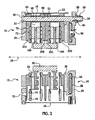
- Figure 2 is a cross-sectional view of the brake of Figure 1 taken along lines 2-2.
- Figure 3 is an exploded perspective view of the brake of Figure 1 .
- Figure 4 is a perspective view of a portion of the brake of Figure 1 .
- Figure 5 is a cross-sectional view of a support column of the brake of Figure 1 .
- FIG. 1 illustrates a brake 10 in accordance with the present invention.
- Brake 10 may be provided for heavy duty industrial use (e.g., on oil drilling equipment).
- brake 10 includes end cap assemblies 12, 14, pins 16, and two sets of friction plates 18A-B, 20A-D.
- brake 10 also includes support columns 22 and guards 24.
- end cap assembly 12 encloses one end of brake 10 and includes an end plate 26.
- Plate 26 may be made from conventional metals and metal alloys. Plate 26 is annular and is disposed about a rotational axis 28 of a drive shaft (not shown). Plate 26 may include a plurality of stepped diameter bores 30 each configured to receive a corresponding pin 16. Plate 26 may also define a plurality of bores 32 configured to receive fasteners (not shown) used to mount brake 10 to another object.
- End cap assembly 14 encloses an opposite axial end of brake 10 relative to end cap assembly 12 and provides support for a brake actuator.
- Assembly 14 includes an end plate 34, an expandable bladder 36 and a pressure plate 38.
- End plate 34 is annular in construction and disposed about axis 28.
- Plate 34 may be made from conventional metal and metal alloys.
- Plate 34 includes a plurality of bores 40 aligned with bores 30 in plate 26 and configured to receive pins 16.
- plate 34 may also define bores 42 on either side of each bore 40 that are aligned with corresponding bores (not shown) in plate 26 for a purpose described hereinbelow.
- plate 34 also defines an annular recess 44 configured to receive bladder 36 and one or more axial bores 46 through which pneumatic or hydraulic fluid is provided to bladder 36 via a hose (not shown).
- Bladder 36 bears against plate 38 to move plate 38 in an axial direction (to the left in Figure 2 ).
- Bladder 36 is conventional in the art and is disposed within recess 44 of end plate 34.
- bladder 36 expands and urges pressure plate 38 in an axial direction to compress, and cause engagement of, friction plates 18A-B, 20A-D.
- springs 48 disposed about pins 16 bias friction plates 20A-B and 20C-D away from both one another and friction plates 18A-B towards their original position.
- Pressure plate 38 engages friction plate 20D and, when fluid is supplied to bladder 36, urges friction plate 20D in an axial direction (to the left in Figure 2 ) to compress friction plates 18A-B, 20A-D.
- Plate 38 may be made from conventional metals and metal alloys. Plate 38 is annular and disposed about axis 26. Plate 38 is configured to receive pins 16 such that plate 38 is capable of axial movement relative to pins 16, but is prevented from rotating relative to pins 16. In particular, and with reference to Figure 3 , plate 38 may include radially outwardly extending flanges 39 defining semicircular recesses configured to receive pins 16 to prevent rotation of plate 38.
- pins 16 provide a mounting structure for friction plates 20A-D and structural support for brake 10.
- Pins 16 are conventional in the art.
- Pins 16 extend axially from end plate 26 to end plate 34 to connect end plates 26, 34.
- Each pin 16 may include a head 50 at one end that abuts against a shoulder formed in a corresponding bore 30 of end plate 26.
- Each pin 16 further includes a shank 52 that terminates in a threaded end 54. The shank 52 of each pin 16 is configured to be received within aligned apertures in friction plates 20A-D and also supports springs 48 between friction plates 20A-B and between friction plates 20C-D.
- Nuts 56 and washers 58 may be disposed about the end 54 of each pin 16 to establish an initial axial position of end plate assemblies 12, 14 and friction plates 18A-B, 20A-D. In the illustrated embodiment, four pins 16 are provided. It should be understood, however, that the number of pins 16 may vary depending on the specific requirements for the brake.
- Friction plates 18A-B are provided to transfer braking torque from friction plates 20A-D to the driven shaft (not shown).
- Friction plates 18A-B may be made from conventional metals and metal alloys such as iron and copper. Plates 18A-B are coupled to a hub 60 fixed to the driven shaft (or directly to the shaft) through the use of spline teeth on a radially inner surface of plates 18A-B and a radially outer surface of hub 60 (or the shaft), respectively. Plates 18A-B may include a conventional friction material 62 connected to each side of plates 18A-B by fasteners (not shown) such as bolts or screws. Although only two plates 18A-B are shown in the illustrated embodiment, it should be understood that additional plates 18 could be interleaved with additional plates 20 to increase braking torque.
- Friction plates 20A-D are provided to transmit a braking torque to friction plates 18A-B and the driven shaft upon engagement of plates 18A-B, 20A-D.
- friction plates 20A-D have a plurality of circumferentially spaced radially outwardly projecting tabs 64 with apertures 66 configured to receive pins 16. In this manner, plates 20A-D are fixed against rotation relative to pins 16, but are axially movable relative to pins 16.
- each of friction plates 20A-D includes one or more cover plates 68 and a fluid jacket 70. Plates 68 are conventional in the art and may be made from a variety of conventional metals and metal alloys including iron or copper.
- Plates 68 close fluid passages defined in fluid jacket 70 and may be connected to fluid jacket 70 using fasteners (not shown) such as bolts or screws or pins.
- Fluid jackets 70 are provided to allow for circulation of a cooling liquid such as water or another conventional liquid within brake 10 to allow for transfer of frictional heat generated within brake 10.
- Jackets 70 are conventional in the art and include an annular body that defines a fluid manifold through which liquid circulates. Jackets 70 may define a plurality of concentric flow passages 72 and radial flow passages 74 that place concentric passages 72 in fluid communication with fluid inlets 76 and outlets (not shown).
- friction plate 20A is disposed at one axial end of brake 10
- friction plate 20D is disposed at an opposite axial end of brake 10
- friction plates 20B-C are arranged back to back intermediate plates 20A,D.
- friction plates 20A-D are identical in construction allowing ease of assembly and manufacture. Although four friction plates 20A-D are shown in the illustrated embodiment, it should be readily understood that additional plates 20 could be interleaved with plates 18 and used to provide increased braking torque.
- support columns 22 provide structural support to brake 10 and provide a means for absorbing braking forces during operation of brake 10.
- a column 22 may be disposed radially outwardly of each pin 16 and extends between end plates 26, 34. Although columns 22 are circumferentially spaced around brake 10 radially outwardly of corresponding pins 16, columns 22 are not necessarily rounded or curved. As shown in Figure 4 , in the illustrated embodiment, columns 22 are substantially rectangular in shape with radially inner and outer surfaces 78, 80 that are substantially flat. Columns 22 may be unitary (i.e., one piece) structures.
- each column 22 defines a recess 82 configured to receive a corresponding pin 16, tabs 64 on friction plates 20A-D and springs 48.
- Columns 22 further include axially extending grooves 84, 86 at each circumferential end between surfaces 78, 80. Grooves 84, 86 are configured to receive corresponding circumferential ends of guards 24.
- each column 22 may further define axially extending closed bores 88, 90, 92, 94 formed in each axial end of column 22. Bores 88, 90, 92 94 are configured to receive fasteners such as bolts, screws, or pins used to fix column 22 to end plates 26, 34.
- Bores 88, 90, 92, 94 may be disposed circumferentially between recess 82 and a corresponding groove 84, 86. Bores 88, 92 and 90, 94, respectively, may be axially aligned.
- bolts or similar fasteners are used to secure columns 22 to end plates 26, 34 in the illustrated embodiment, it should be understood that other fasteners (e.g., welds) might be used and that columns 22 may be connected to end plates 26, 34, in a variety of ways. It should also be understood that columns 22 could be constructed and oriented so as to be disposed radially outwardly of more than one pin 16. The illustrated arrangement provides potentially greater reductions in weight, but larger columns could be used without departing from the spirit of the present invention.
- guards 24 limit access to moving components of brake 10 to prevent damage to brake 10 from foreign objects or injuries to users.
- Guards 24 may be made from metals or metal alloys including steel.
- Guards 24 are spaced circumferentially around brake 10 between columns 22. Each circumferential end of a guard 24 is received within a corresponding groove 84, 86 of a column 22 and are slid into grooves 84, 86 from one axial end of brake 10.
- Guards 24 may be ventilated to allow dissipation of heat and reduce weight.
- each guard 24 may include a plurality of vents 96 extend longitudinally in a circumferential direction. It should be understood, however, that the number, size and shape of vents 96 may vary.
- one or more guards 24 may also include apertures 98 sized to receive hoses and connectors through which fluid is provided to the inlets 76 and removed through the outlets of fluid jackets 70.
- a brake in accordance with the present invention represents a significant improvement relative to conventional liquid cooled brakes.
- Columns 22 provide structural support and absorb braking forces during operation of brake 10 thereby removing undue strain on pins 16. In this manner, brake 10 is able to remove undue stress on pins 16 without the excessive weight resulting from the use of solid rings. Further, the columns can be used on brakes of varying diameters providing a scalable solution.
Landscapes
- Engineering & Computer Science (AREA)
- General Engineering & Computer Science (AREA)
- Mechanical Engineering (AREA)
- Braking Arrangements (AREA)
- Lasers (AREA)
Abstract
Description
- This invention relates to liquid cooled brakes and, more particularly, to a liquid cooled brake in which support columns are used to provide a lightweight yet strong supporting housing.
- A conventional liquid cooled disc brake includes a stationary housing disposed about a rotating shaft. A plurality of friction plates are coupled to the housing and fixed against rotation relative to the housing, but axially moveable relative to the housing. These friction plates define fluid jackets through which cooling liquids are circulated. Another plurality of friction plates are coupled to the shaft for rotation therewith and are axially movable relative to the shaft. The plates coupled to the shaft are interleaved with the plates coupled to the housing. A brake actuator is disposed at one axial end of the brake and applies a force in an axial direction to bring the plates into contact with one another.
US 6,029,782 discloses a brake having multiple actuators. The brake comprises a torque transmission assembly centered about a longitudinal axis, a hub that is rotatable about the axis, and first and second pressure plate assemblies that are axially movable relative to the torque transmission assembly and each other. The brake also includes a drive plate assembly responsive to axial movement of the first pressure plate assembly for braking the rotation of the hub relative to the torque transmission assembly. Springs urge the second pressure plate assembly in a first axial direction towards the first pressure plate assembly and the first pressure plate assembly towards the drive plate assembly thereby setting the brake. One actuator is used to urge the second pressure plate assembly in a second axial direction, opposite the first axial direction and away from the first pressure plate assembly, to thereby release the brake. Another actuator is used to again urge the first pressure plate assembly in the first axial direction to control braking torque. - The housing for conventional liquid cooled brakes typically includes one or more rings encircling the friction plates. These rings are generally solid, relatively heavy and must be customized to the diameter of the brake. Other conventional liquid cooled brakes have eliminated the rings and have instead used a plurality of pins extending between end plates of the brake. This arrangement is disadvantageous, however, because the pins are required to provide both structural support to the brake and absorb braking forces during operation of the brake creating undue strain on the pins.
- The inventors herein have recognized a need for brake that will minimize and/or eliminate one or more of the above-identified deficiencies.
- The present invention provides a liquid cooled brake having an improved structural support.
- A brake in accordance with the present invention includes first and second end plates disposed about a driven shaft. The driven shaft rotates about a rotational axis and the first and second end plates are axially spaced from one another. A plurality of axially extending pins connect the first and second end plates. A first friction plate is coupled to the driven shaft for rotation therewith and is axially movable relative to the driven shaft. A second friction plate is coupled to the plurality of pins. The second friction plate is fixed against rotation relative to the plurality of pins, but is axially movable relative to the plurality of pins. The second friction plate defines a fluid jacket configured for passage of a fluid. A pressure plate is configured for selective movement in a first axial direction towards the first and second friction plates. A first support column is disposed radially outwardly of a first pin of the plurality of pins and is fixed at first and second ends to the first and second end plates, respectively. Additional support columns may be disposed radially outwardly of additional corresponding pins of the plurality of pins and fixed to the first and second end plates.
- A brake in accordance with the present invention represents a significant improvement relative to conventional liquid cooled brakes. In particular, the use of support columns between the end plates of the inventive brake reduces strain on the pins and provides a housing with improved structural support that is strong, yet lightweight and scalable.
- These and other advantages of this invention will become apparent to one skilled in the art from the following detailed description and the accompanying drawings illustrating features of this invention by way of example.
-
Figure 1 is a perspective view of a brake in accordance with the present invention. -
Figure 2 is a cross-sectional view of the brake ofFigure 1 taken along lines 2-2. -
Figure 3 is an exploded perspective view of the brake ofFigure 1 . -
Figure 4 is a perspective view of a portion of the brake ofFigure 1 . -
Figure 5 is a cross-sectional view of a support column of the brake ofFigure 1 . - Referring now to the drawings wherein like reference numerals are used to identify identical components in the various views,
Figure 1 illustrates abrake 10 in accordance with the present invention. Brake 10 may be provided for heavy duty industrial use (e.g., on oil drilling equipment). Referring toFigures 2-3 ,brake 10 includesend cap assemblies pins 16, and two sets offriction plates 18A-B, 20A-D. Referring toFigures 1 and3 , in accordance with theinvention brake 10 also includessupport columns 22 andguards 24. - Referring to
Figure 2 ,end cap assembly 12 encloses one end ofbrake 10 and includes anend plate 26.Plate 26 may be made from conventional metals and metal alloys.Plate 26 is annular and is disposed about arotational axis 28 of a drive shaft (not shown).Plate 26 may include a plurality ofstepped diameter bores 30 each configured to receive acorresponding pin 16.Plate 26 may also define a plurality ofbores 32 configured to receive fasteners (not shown) used to mountbrake 10 to another object. -
End cap assembly 14 encloses an opposite axial end ofbrake 10 relative toend cap assembly 12 and provides support for a brake actuator.Assembly 14 includes anend plate 34, anexpandable bladder 36 and apressure plate 38. -
End plate 34 is annular in construction and disposed aboutaxis 28.Plate 34 may be made from conventional metal and metal alloys.Plate 34 includes a plurality ofbores 40 aligned withbores 30 inplate 26 and configured to receivepins 16. Referring toFigures 1 and3 ,plate 34 may also definebores 42 on either side of eachbore 40 that are aligned with corresponding bores (not shown) inplate 26 for a purpose described hereinbelow. Referring again toFigure 2 ,plate 34 also defines anannular recess 44 configured to receivebladder 36 and one or moreaxial bores 46 through which pneumatic or hydraulic fluid is provided tobladder 36 via a hose (not shown). -
Bladder 36 bears againstplate 38 to moveplate 38 in an axial direction (to the left inFigure 2 ). Bladder 36 is conventional in the art and is disposed withinrecess 44 ofend plate 34. When fluid is supplied tobladder 36,bladder 36 expands and urgespressure plate 38 in an axial direction to compress, and cause engagement of,friction plates 18A-B, 20A-D. When fluid pressure is removed frombladder 36,springs 48 disposed aboutpins 16bias friction plates 20A-B and 20C-D away from both one another andfriction plates 18A-B towards their original position. -
Pressure plate 38 engagesfriction plate 20D and, when fluid is supplied tobladder 36, urgesfriction plate 20D in an axial direction (to the left inFigure 2 ) to compressfriction plates 18A-B, 20A-D. Plate 38 may be made from conventional metals and metal alloys.Plate 38 is annular and disposed aboutaxis 26.Plate 38 is configured to receivepins 16 such thatplate 38 is capable of axial movement relative topins 16, but is prevented from rotating relative to pins 16. In particular, and with reference toFigure 3 ,plate 38 may include radially outwardly extendingflanges 39 defining semicircular recesses configured to receivepins 16 to prevent rotation ofplate 38. - Referring again to
Figure 2 , pins 16 provide a mounting structure forfriction plates 20A-D and structural support forbrake 10.Pins 16 are conventional in the art.Pins 16 extend axially fromend plate 26 toend plate 34 to connectend plates pin 16 may include ahead 50 at one end that abuts against a shoulder formed in acorresponding bore 30 ofend plate 26. Eachpin 16 further includes ashank 52 that terminates in a threadedend 54. Theshank 52 of eachpin 16 is configured to be received within aligned apertures infriction plates 20A-D and also supportssprings 48 betweenfriction plates 20A-B and betweenfriction plates 20C-D. Nuts 56 andwashers 58 may be disposed about theend 54 of eachpin 16 to establish an initial axial position ofend plate assemblies friction plates 18A-B, 20A-D. In the illustrated embodiment, fourpins 16 are provided. It should be understood, however, that the number ofpins 16 may vary depending on the specific requirements for the brake. -
Friction plates 18A-B are provided to transfer braking torque fromfriction plates 20A-D to the driven shaft (not shown).Friction plates 18A-B may be made from conventional metals and metal alloys such as iron and copper.Plates 18A-B are coupled to ahub 60 fixed to the driven shaft (or directly to the shaft) through the use of spline teeth on a radially inner surface ofplates 18A-B and a radially outer surface of hub 60 (or the shaft), respectively.Plates 18A-B may include aconventional friction material 62 connected to each side ofplates 18A-B by fasteners (not shown) such as bolts or screws. Although only twoplates 18A-B are shown in the illustrated embodiment, it should be understood that additional plates 18 could be interleaved with additional plates 20 to increase braking torque. -
Friction plates 20A-D are provided to transmit a braking torque tofriction plates 18A-B and the driven shaft upon engagement ofplates 18A-B, 20A-D. Referring toFigure 3 ,friction plates 20A-D have a plurality of circumferentially spaced radially outwardly projectingtabs 64 withapertures 66 configured to receive pins 16. In this manner,plates 20A-D are fixed against rotation relative topins 16, but are axially movable relative to pins 16. Referring again toFigure 2 , each offriction plates 20A-D includes one ormore cover plates 68 and afluid jacket 70.Plates 68 are conventional in the art and may be made from a variety of conventional metals and metal alloys including iron or copper.Plates 68 close fluid passages defined influid jacket 70 and may be connected tofluid jacket 70 using fasteners (not shown) such as bolts or screws or pins.Fluid jackets 70 are provided to allow for circulation of a cooling liquid such as water or another conventional liquid withinbrake 10 to allow for transfer of frictional heat generated withinbrake 10.Jackets 70 are conventional in the art and include an annular body that defines a fluid manifold through which liquid circulates.Jackets 70 may define a plurality ofconcentric flow passages 72 andradial flow passages 74 that placeconcentric passages 72 in fluid communication withfluid inlets 76 and outlets (not shown). In the illustrate embodiment,friction plate 20A is disposed at one axial end ofbrake 10,friction plate 20D is disposed at an opposite axial end ofbrake 10 andfriction plates 20B-C are arranged back to backintermediate plates 20A,D. In accordance with one aspect of the present invention,friction plates 20A-D are identical in construction allowing ease of assembly and manufacture. Although fourfriction plates 20A-D are shown in the illustrated embodiment, it should be readily understood that additional plates 20 could be interleaved with plates 18 and used to provide increased braking torque. - Referring again to
Figures 1 and3 ,support columns 22 provide structural support to brake 10 and provide a means for absorbing braking forces during operation ofbrake 10. Acolumn 22 may be disposed radially outwardly of eachpin 16 and extends betweenend plates columns 22 are circumferentially spaced aroundbrake 10 radially outwardly ofcorresponding pins 16,columns 22 are not necessarily rounded or curved. As shown inFigure 4 , in the illustrated embodiment,columns 22 are substantially rectangular in shape with radially inner andouter surfaces Columns 22 may be unitary (i.e., one piece) structures. The radiallyinner surface 80 of eachcolumn 22 defines arecess 82 configured to receive acorresponding pin 16,tabs 64 onfriction plates 20A-D and springs 48.Columns 22 further include axially extendinggrooves surfaces Grooves guards 24. Referring toFigure 5 , eachcolumn 22 may further define axially extendingclosed bores column 22.Bores column 22 toend plates Bores recess 82 and a correspondinggroove Bores columns 22 toend plates columns 22 may be connected to endplates columns 22 could be constructed and oriented so as to be disposed radially outwardly of more than onepin 16. The illustrated arrangement provides potentially greater reductions in weight, but larger columns could be used without departing from the spirit of the present invention. - Referring again to
Figure 4 , guards 24 limit access to moving components ofbrake 10 to prevent damage to brake 10 from foreign objects or injuries to users.Guards 24 may be made from metals or metal alloys including steel.Guards 24 are spaced circumferentially aroundbrake 10 betweencolumns 22. Each circumferential end of aguard 24 is received within a correspondinggroove column 22 and are slid intogrooves brake 10.Guards 24 may be ventilated to allow dissipation of heat and reduce weight. In particular, eachguard 24 may include a plurality ofvents 96 extend longitudinally in a circumferential direction. It should be understood, however, that the number, size and shape ofvents 96 may vary. Referring again toFigures 1 and3 , one ormore guards 24 may also includeapertures 98 sized to receive hoses and connectors through which fluid is provided to theinlets 76 and removed through the outlets offluid jackets 70. - A brake in accordance with the present invention represents a significant improvement relative to conventional liquid cooled brakes.
Columns 22 provide structural support and absorb braking forces during operation ofbrake 10 thereby removing undue strain on pins 16. In this manner,brake 10 is able to remove undue stress onpins 16 without the excessive weight resulting from the use of solid rings. Further, the columns can be used on brakes of varying diameters providing a scalable solution. - While the invention has been shown and described with reference to one or more particular embodiments thereof, it will be understood by those of skill in the art that various changes and modifications can be made without departing from the scope of the invention as defined in the appended claims.
Claims (15)
- A brake (10), comprising:first and second end plates (2.6, 34) disposed about a driven shaft, said driven shaft rotating about a rotational axis (28) and said first and second end plates (26, 34) axially spaced from one anothera plurality of axially extending pins (16) connecting said first and second end plates (26, 34);a first friction plate (18) coupled to said driven shaft for rotation therewith and axially movable relative to said driven shaft;a second friction plate (20) coupled to said plurality of pins (16) and fixed against rotation relative to said plurality of pins (16), but axially movable relative to said plurality of pins (16), said second friction plate (20) defining a fluid jacket (70) configured for passage of a fluid;a pressure plate (38) configured for selective movement in a first axial direction towards said first and second friction plates (18, 20); and,characterized by:a first support column (22) disposed radially outwardly of a first pin of said plurality of pins (16) and said second friction plate (20)and fixed at first and second ends to said first and second end plates (26, 34), respectively.
- The brake (10) of claim 1 wherein said first support column (22) is disposed radially outwardly of less than all of said plurality of pins (16).
- The brake (10) of claim 1, further comprising a second support column (22) disposed radially outwardly of a second pin of said plurality of pins (16) and said second friction plate (20) and fixed at first and second ends to said first said first and second end plates (26, 34), respectively.
- The brake (10) of claim 3, further comprising a first guard (24) connected to said first and second support columns (22), said first guard (24) disposed circumferentially between said first and second support columns (22).
- The brake (10) of claim 4 wherein each of said first and second support columns (22) includes an axially extending groove (84, 86) at one circumferential end, said axially ending grooves (84, 86) of said first and second support columns (22) opening towards one another and configured to receive opposite circumferential ends of said first guard (24).
- The brake (10) of claim 4 wherein said first guard (24) is ventilated.
- The brake (10) of claim 3 wherein said second support column (22) is circumferentially spaced from said first support column (22).
- The brake (10) of claim 1 wherein said first support column (22) is a unitary structure.
- The brake (10) of claim 1 wherein said first support column (22) defines a recess (82) on a radially inward side of said first support column (22) configured to receive said first pin (16) and said second friction plate (20).
- The brake (10) of claim 1 wherein said first support column (22) defines first and second axially extending bores (88, 92) configured to receive fasteners fixing said first and second ends of said first support column (22) to said first and second end plates (26, 34).
- The brake (10) of claim 1 further comprising third and fourth friction plates (20) coupled to said plurality of pins (16) and fixed against rotation relative to said plurality of pins (16), but axially movable relative to said plurality of pins (16), said third and fourth friction plates (20) defining fluid jackets (70) configured for passage of said fluid
wherein said second friction plate (20) is disposed proximate one axial end of said brake (10), said third friction plate (20) is disposed proximate another axial end of said brake (10) and said fourth friction plate (20) is disposed intermediate said second and third friction plates (20), said second, third and fourth friction plates (20) identical in construction. - The brake (10) of claim 1, further comprising one or more further support columns which with the first support column form a plurality of support columns, each support column of said plurality support columns (22) disposed radially outwardly of a corresponding pin of said plurality of pins (16) and said second friction plate (20) and fixed at first and second ends to said first and second end plates (26, 34), respectively.
- The brake (10) of claim 12, further comprising a plurality of guards (24), each guard (24) disposed circumferentially between, and connected to, two support columns (22) of said plurality of support columns.
- The brake (10) of claim 13 wherein each support column (22) of said plurality of support columns includes first and second axially extending grooves (84, 86) located at opposite circumferential ends of said support column (22), said first axially extending groove (84) configured to receive a circumferential end of one of said plurality of guards and said second axially extending groove (86) configured to receive a circumferential end of another of said plurality of guards.
- The brake (10) of claim 12 wherein each support column of said plurality of support columns (22) defines a recess (82) on a radially inward side of said support column configured to receive a corresponding pin of said plurality of pins (16) and said second friction plate (20).
Applications Claiming Priority (2)
| Application Number | Priority Date | Filing Date | Title |
|---|---|---|---|
| US11/670,698 US8776955B2 (en) | 2007-02-02 | 2007-02-02 | Liquid cooled brake with support columns |
| PCT/US2008/052265 WO2008097754A1 (en) | 2007-02-02 | 2008-01-29 | Liquid cooled brake with support columns |
Publications (2)
| Publication Number | Publication Date |
|---|---|
| EP2115316A1 EP2115316A1 (en) | 2009-11-11 |
| EP2115316B1 true EP2115316B1 (en) | 2011-01-12 |
Family
ID=39368462
Family Applications (1)
| Application Number | Title | Priority Date | Filing Date |
|---|---|---|---|
| EP08714083A Active EP2115316B1 (en) | 2007-02-02 | 2008-01-29 | Liquid cooled brake with support columns |
Country Status (9)
| Country | Link |
|---|---|
| US (2) | US8776955B2 (en) |
| EP (1) | EP2115316B1 (en) |
| CN (1) | CN101622467B (en) |
| AT (1) | ATE495385T1 (en) |
| AU (1) | AU2008214106B2 (en) |
| CL (1) | CL2008000301A1 (en) |
| DE (1) | DE602008004445D1 (en) |
| WO (1) | WO2008097754A1 (en) |
| ZA (1) | ZA200905050B (en) |
Families Citing this family (14)
| Publication number | Priority date | Publication date | Assignee | Title |
|---|---|---|---|---|
| US8245827B2 (en) * | 2006-10-31 | 2012-08-21 | Eaton Corporation | Clutch brake assembly |
| US8813936B2 (en) * | 2008-07-25 | 2014-08-26 | Eaton Corporation | Force transmitting assembly |
| US9140324B2 (en) * | 2009-04-24 | 2015-09-22 | Eaton Corporation | Fluid cooled coupling assembly |
| US8752680B2 (en) * | 2012-07-16 | 2014-06-17 | Eaton Corporation | Multi-chambered, liquid-cooled disc brake |
| EP2475646B1 (en) | 2009-07-29 | 2017-06-21 | Bayer Intellectual Property GmbH | 4-(3-alkylthiobenzoyl)pyrazoles and their use as herbicides |
| US8662274B2 (en) | 2012-03-13 | 2014-03-04 | Warner Electric Technology Llc | Rotational coupling device with improved actuator assembly |
| US8919514B2 (en) | 2012-03-28 | 2014-12-30 | Eaton Corporation | Floating housing force transmitting assembly |
| CN103912611A (en) * | 2013-01-09 | 2014-07-09 | 常州施瑞特机械有限公司 | Multi-disc brake of air compressor |
| WO2015000558A1 (en) * | 2013-07-01 | 2015-01-08 | Bobst Mex Sa | Device for braking a reel of tape |
| CN103883645B (en) * | 2014-04-13 | 2016-09-14 | 福建亚南电机有限公司 | A kind of two grades of change speed gear box cut spring antifriction system and devices of the through vehicle bridge of pure electric vehicle |
| ES2705358B2 (en) * | 2017-09-22 | 2019-09-11 | Beneitez Jose Maria Gomez | BRAKE DEVICE |
| US11174908B2 (en) * | 2019-04-04 | 2021-11-16 | Warner Electric Technology Llc | Miniature brake and method of assembly |
| EP3753793B1 (en) * | 2019-06-21 | 2023-02-22 | Goodrich Corporation | Braking system for an aircraft wheel |
| ES2792148B2 (en) * | 2020-02-07 | 2021-10-18 | Brl Brake Solutions S L | IMPROVED BRAKING DEVICE |
Family Cites Families (31)
| Publication number | Priority date | Publication date | Assignee | Title |
|---|---|---|---|---|
| US2655236A (en) * | 1949-05-25 | 1953-10-13 | American Steel Foundries | Disk brake |
| US3051528A (en) * | 1960-08-15 | 1962-08-28 | Bendix Corp | Segmented heat shield for wheels |
| US3031528A (en) | 1960-11-01 | 1962-04-24 | Gen Motors Corp | Loudness meter |
| US3572477A (en) | 1968-11-25 | 1971-03-30 | Madill Ltd S | Liquid cooled brake |
| US3599760A (en) | 1969-01-07 | 1971-08-17 | Wichita Clutch Co Inc | Spring set fluid release brake |
| US3830345A (en) | 1973-04-24 | 1974-08-20 | E Boyles | Disk brakes |
| US3862678A (en) | 1973-08-02 | 1975-01-28 | Eaton Corp | Cooled coupling with disc stops |
| US3999634A (en) | 1974-01-14 | 1976-12-28 | Howell Industries, Inc. | Pneumatic actuation for disc brake assemblies |
| US4017123A (en) * | 1976-04-02 | 1977-04-12 | The Bendix Corporation | Dual layer heat shield for wheels |
| US4102438A (en) * | 1976-10-18 | 1978-07-25 | The Dolphin Brake Corp. | Disc brake assembly |
| US4084857A (en) * | 1976-12-20 | 1978-04-18 | The Bendix Corporation | Drive key heat shield and support for wheel rim heat shield of multiple disc brake |
| DE2821696A1 (en) | 1978-05-18 | 1979-11-22 | Rietschoten & Houwens Gmbh | Actuator for paper machinery disc brake - has piston, cylinder and connecting rod acting on plate which in turn presses on pressure ring |
| US4383594A (en) * | 1981-06-08 | 1983-05-17 | Goodyear Aerospace Corporation | Configuration for a disk brake torque tube assembly having replaceable keys and backplate |
| US4609076A (en) | 1983-09-01 | 1986-09-02 | Eaton Corporation | Spring engaged fluid released multi-disc brake assembly |
| US4635761A (en) * | 1985-08-30 | 1987-01-13 | Allied Corporation | Disc brake parking cartridge retention device |
| US4977991A (en) * | 1989-08-28 | 1990-12-18 | Delta Clutch, Inc. | Multiple disc clutch |
| US5851056A (en) * | 1996-06-03 | 1998-12-22 | The B. F. Goodrich Company | Aircraft brake heat shield having easily removed heat shield sections |
| US6029782A (en) | 1998-03-24 | 2000-02-29 | Dana Corporation | Multiple actuator brake |
| FR2786239B1 (en) * | 1998-11-25 | 2001-02-16 | Messier Bugatti | PNEUMATICALLY CONTROLLED DISC FRICTION DEVICE FOR TRANSMISSION |
| US6405837B1 (en) * | 2000-02-10 | 2002-06-18 | Mico Incorporated | Combined parking and service brake |
| US6516924B1 (en) * | 2000-06-12 | 2003-02-11 | Ausco Products, Inc. | Vehicle brake system |
| US6491139B1 (en) * | 2000-11-15 | 2002-12-10 | Lauro Budica | Fluid-cooled brake system |
| DE10061460A1 (en) * | 2000-12-08 | 2002-06-13 | Zf Sachs Ag | friction clutch |
| EP1409885A1 (en) | 2001-02-21 | 2004-04-21 | Group Newtech International Inc. | Brake wear compensator |
| US7051845B2 (en) * | 2001-10-10 | 2006-05-30 | Goodrich Corporation | Heat shield assembly for aircraft wheel and brake assembly |
| US7055657B2 (en) * | 2004-01-20 | 2006-06-06 | George Reisch Aschauer | Wet friction device with inward and outward circulating cooling means |
| US7475762B2 (en) * | 2004-05-25 | 2009-01-13 | Honeywell International Inc. | Aircraft wheel part having improved corrosion resistance |
| US7556128B2 (en) | 2005-10-31 | 2009-07-07 | Warner Electric Technology Llc | Dual actuator friction brake assembly |
| US7591349B2 (en) | 2005-10-31 | 2009-09-22 | Warner Electric Technology Llc | Liquid cooled brake assembly |
| US7374027B2 (en) | 2005-10-31 | 2008-05-20 | Warner Electric Technology Llc | Balanced flow cooling water jacket |
| US7390067B2 (en) * | 2006-04-05 | 2008-06-24 | Honeywell International Inc. | Apparatus and methods for wheel balancing via rotor drive keys |
-
2007
- 2007-02-02 US US11/670,698 patent/US8776955B2/en active Active
-
2008
- 2008-01-29 AU AU2008214106A patent/AU2008214106B2/en not_active Ceased
- 2008-01-29 DE DE602008004445T patent/DE602008004445D1/en active Active
- 2008-01-29 CN CN2008800038232A patent/CN101622467B/en active Active
- 2008-01-29 ZA ZA200905050A patent/ZA200905050B/en unknown
- 2008-01-29 EP EP08714083A patent/EP2115316B1/en active Active
- 2008-01-29 AT AT08714083T patent/ATE495385T1/en not_active IP Right Cessation
- 2008-01-29 WO PCT/US2008/052265 patent/WO2008097754A1/en not_active Ceased
- 2008-01-31 CL CL200800301A patent/CL2008000301A1/en unknown
-
2014
- 2014-07-15 US US14/331,477 patent/US9309941B2/en active Active
Also Published As
| Publication number | Publication date |
|---|---|
| US9309941B2 (en) | 2016-04-12 |
| HK1135751A1 (en) | 2010-06-11 |
| US8776955B2 (en) | 2014-07-15 |
| WO2008097754A1 (en) | 2008-08-14 |
| ATE495385T1 (en) | 2011-01-15 |
| ZA200905050B (en) | 2010-09-29 |
| CN101622467A (en) | 2010-01-06 |
| CN101622467B (en) | 2012-11-28 |
| EP2115316A1 (en) | 2009-11-11 |
| US20140318904A1 (en) | 2014-10-30 |
| US20080185239A1 (en) | 2008-08-07 |
| AU2008214106B2 (en) | 2011-09-08 |
| CL2008000301A1 (en) | 2008-06-06 |
| AU2008214106A1 (en) | 2008-08-14 |
| DE602008004445D1 (en) | 2011-02-24 |
Similar Documents
| Publication | Publication Date | Title |
|---|---|---|
| US9309941B2 (en) | Liquid cooled brake with support columns | |
| US7766134B2 (en) | Balanced flow cooling water jacket | |
| US7900752B2 (en) | Dual actuator friction brake assembly | |
| JPH0222507Y2 (en) | ||
| EP0136434B1 (en) | Disc brake | |
| EP3611396B1 (en) | Multi-layer thermal insulator for brake piston | |
| CA1176580A (en) | Electric motor brake unit | |
| US6029782A (en) | Multiple actuator brake | |
| EP1943433B1 (en) | Liquid cooled brake assembly | |
| US20020000356A1 (en) | Clutch | |
| EP1917450B1 (en) | Self aligning brake kit | |
| US2125559A (en) | Coupling for the transmission of power or movement | |
| US5794751A (en) | Piston for torque transmitting systems | |
| US4569428A (en) | Actuator for friction coupling | |
| HK1135751B (en) | Liquid cooled brake with support columns | |
| KR20240089582A (en) | brake device | |
| CN115667751A (en) | Hydraulic machine comprising a stack of discs acted on by a push rod | |
| CN223408120U (en) | Fully electric brake main wheel |
Legal Events
| Date | Code | Title | Description |
|---|---|---|---|
| PUAI | Public reference made under article 153(3) epc to a published international application that has entered the european phase |
Free format text: ORIGINAL CODE: 0009012 |
|
| 17P | Request for examination filed |
Effective date: 20090826 |
|
| AK | Designated contracting states |
Kind code of ref document: A1 Designated state(s): AT BE BG CH CY CZ DE DK EE ES FI FR GB GR HR HU IE IS IT LI LT LU LV MC MT NL NO PL PT RO SE SI SK TR |
|
| 17Q | First examination report despatched |
Effective date: 20091223 |
|
| DAX | Request for extension of the european patent (deleted) | ||
| GRAP | Despatch of communication of intention to grant a patent |
Free format text: ORIGINAL CODE: EPIDOSNIGR1 |
|
| GRAS | Grant fee paid |
Free format text: ORIGINAL CODE: EPIDOSNIGR3 |
|
| GRAA | (expected) grant |
Free format text: ORIGINAL CODE: 0009210 |
|
| AK | Designated contracting states |
Kind code of ref document: B1 Designated state(s): AT BE BG CH CY CZ DE DK EE ES FI FR GB GR HR HU IE IS IT LI LT LU LV MC MT NL NO PL PT RO SE SI SK TR |
|
| REG | Reference to a national code |
Ref country code: GB Ref legal event code: FG4D |
|
| REG | Reference to a national code |
Ref country code: CH Ref legal event code: EP |
|
| REG | Reference to a national code |
Ref country code: NL Ref legal event code: T3 |
|
| REG | Reference to a national code |
Ref country code: IE Ref legal event code: FG4D |
|
| REF | Corresponds to: |
Ref document number: 602008004445 Country of ref document: DE Date of ref document: 20110224 Kind code of ref document: P |
|
| REG | Reference to a national code |
Ref country code: DE Ref legal event code: R096 Ref document number: 602008004445 Country of ref document: DE Effective date: 20110224 |
|
| REG | Reference to a national code |
Ref country code: RO Ref legal event code: EPE |
|
| LTIE | Lt: invalidation of european patent or patent extension |
Effective date: 20110112 |
|
| PG25 | Lapsed in a contracting state [announced via postgrant information from national office to epo] |
Ref country code: PT Free format text: LAPSE BECAUSE OF FAILURE TO SUBMIT A TRANSLATION OF THE DESCRIPTION OR TO PAY THE FEE WITHIN THE PRESCRIBED TIME-LIMIT Effective date: 20110512 Ref country code: SE Free format text: LAPSE BECAUSE OF FAILURE TO SUBMIT A TRANSLATION OF THE DESCRIPTION OR TO PAY THE FEE WITHIN THE PRESCRIBED TIME-LIMIT Effective date: 20110112 Ref country code: IS Free format text: LAPSE BECAUSE OF FAILURE TO SUBMIT A TRANSLATION OF THE DESCRIPTION OR TO PAY THE FEE WITHIN THE PRESCRIBED TIME-LIMIT Effective date: 20110512 Ref country code: LT Free format text: LAPSE BECAUSE OF FAILURE TO SUBMIT A TRANSLATION OF THE DESCRIPTION OR TO PAY THE FEE WITHIN THE PRESCRIBED TIME-LIMIT Effective date: 20110112 Ref country code: GR Free format text: LAPSE BECAUSE OF FAILURE TO SUBMIT A TRANSLATION OF THE DESCRIPTION OR TO PAY THE FEE WITHIN THE PRESCRIBED TIME-LIMIT Effective date: 20110413 Ref country code: HR Free format text: LAPSE BECAUSE OF FAILURE TO SUBMIT A TRANSLATION OF THE DESCRIPTION OR TO PAY THE FEE WITHIN THE PRESCRIBED TIME-LIMIT Effective date: 20110112 Ref country code: NO Free format text: LAPSE BECAUSE OF FAILURE TO SUBMIT A TRANSLATION OF THE DESCRIPTION OR TO PAY THE FEE WITHIN THE PRESCRIBED TIME-LIMIT Effective date: 20110412 Ref country code: LV Free format text: LAPSE BECAUSE OF FAILURE TO SUBMIT A TRANSLATION OF THE DESCRIPTION OR TO PAY THE FEE WITHIN THE PRESCRIBED TIME-LIMIT Effective date: 20110112 Ref country code: ES Free format text: LAPSE BECAUSE OF FAILURE TO SUBMIT A TRANSLATION OF THE DESCRIPTION OR TO PAY THE FEE WITHIN THE PRESCRIBED TIME-LIMIT Effective date: 20110423 |
|
| PG25 | Lapsed in a contracting state [announced via postgrant information from national office to epo] |
Ref country code: CY Free format text: LAPSE BECAUSE OF FAILURE TO SUBMIT A TRANSLATION OF THE DESCRIPTION OR TO PAY THE FEE WITHIN THE PRESCRIBED TIME-LIMIT Effective date: 20110112 Ref country code: AT Free format text: LAPSE BECAUSE OF FAILURE TO SUBMIT A TRANSLATION OF THE DESCRIPTION OR TO PAY THE FEE WITHIN THE PRESCRIBED TIME-LIMIT Effective date: 20110112 Ref country code: MC Free format text: LAPSE BECAUSE OF NON-PAYMENT OF DUE FEES Effective date: 20110131 Ref country code: BG Free format text: LAPSE BECAUSE OF FAILURE TO SUBMIT A TRANSLATION OF THE DESCRIPTION OR TO PAY THE FEE WITHIN THE PRESCRIBED TIME-LIMIT Effective date: 20110412 Ref country code: SI Free format text: LAPSE BECAUSE OF FAILURE TO SUBMIT A TRANSLATION OF THE DESCRIPTION OR TO PAY THE FEE WITHIN THE PRESCRIBED TIME-LIMIT Effective date: 20110112 Ref country code: PL Free format text: LAPSE BECAUSE OF FAILURE TO SUBMIT A TRANSLATION OF THE DESCRIPTION OR TO PAY THE FEE WITHIN THE PRESCRIBED TIME-LIMIT Effective date: 20110112 Ref country code: BE Free format text: LAPSE BECAUSE OF FAILURE TO SUBMIT A TRANSLATION OF THE DESCRIPTION OR TO PAY THE FEE WITHIN THE PRESCRIBED TIME-LIMIT Effective date: 20110112 Ref country code: FI Free format text: LAPSE BECAUSE OF FAILURE TO SUBMIT A TRANSLATION OF THE DESCRIPTION OR TO PAY THE FEE WITHIN THE PRESCRIBED TIME-LIMIT Effective date: 20110112 |
|
| REG | Reference to a national code |
Ref country code: IE Ref legal event code: MM4A |
|
| PG25 | Lapsed in a contracting state [announced via postgrant information from national office to epo] |
Ref country code: DK Free format text: LAPSE BECAUSE OF FAILURE TO SUBMIT A TRANSLATION OF THE DESCRIPTION OR TO PAY THE FEE WITHIN THE PRESCRIBED TIME-LIMIT Effective date: 20110112 Ref country code: EE Free format text: LAPSE BECAUSE OF FAILURE TO SUBMIT A TRANSLATION OF THE DESCRIPTION OR TO PAY THE FEE WITHIN THE PRESCRIBED TIME-LIMIT Effective date: 20110112 |
|
| PLBE | No opposition filed within time limit |
Free format text: ORIGINAL CODE: 0009261 |
|
| STAA | Information on the status of an ep patent application or granted ep patent |
Free format text: STATUS: NO OPPOSITION FILED WITHIN TIME LIMIT |
|
| PG25 | Lapsed in a contracting state [announced via postgrant information from national office to epo] |
Ref country code: CZ Free format text: LAPSE BECAUSE OF FAILURE TO SUBMIT A TRANSLATION OF THE DESCRIPTION OR TO PAY THE FEE WITHIN THE PRESCRIBED TIME-LIMIT Effective date: 20110112 Ref country code: SK Free format text: LAPSE BECAUSE OF FAILURE TO SUBMIT A TRANSLATION OF THE DESCRIPTION OR TO PAY THE FEE WITHIN THE PRESCRIBED TIME-LIMIT Effective date: 20110112 |
|
| 26N | No opposition filed |
Effective date: 20111013 |
|
| PG25 | Lapsed in a contracting state [announced via postgrant information from national office to epo] |
Ref country code: MT Free format text: LAPSE BECAUSE OF FAILURE TO SUBMIT A TRANSLATION OF THE DESCRIPTION OR TO PAY THE FEE WITHIN THE PRESCRIBED TIME-LIMIT Effective date: 20110112 Ref country code: IT Free format text: LAPSE BECAUSE OF FAILURE TO SUBMIT A TRANSLATION OF THE DESCRIPTION OR TO PAY THE FEE WITHIN THE PRESCRIBED TIME-LIMIT Effective date: 20110112 |
|
| REG | Reference to a national code |
Ref country code: FR Ref legal event code: ST Effective date: 20111125 |
|
| PG25 | Lapsed in a contracting state [announced via postgrant information from national office to epo] |
Ref country code: FR Free format text: LAPSE BECAUSE OF NON-PAYMENT OF DUE FEES Effective date: 20110314 Ref country code: IE Free format text: LAPSE BECAUSE OF NON-PAYMENT OF DUE FEES Effective date: 20110129 |
|
| REG | Reference to a national code |
Ref country code: DE Ref legal event code: R097 Ref document number: 602008004445 Country of ref document: DE Effective date: 20111013 |
|
| REG | Reference to a national code |
Ref country code: CH Ref legal event code: PL |
|
| PG25 | Lapsed in a contracting state [announced via postgrant information from national office to epo] |
Ref country code: CH Free format text: LAPSE BECAUSE OF NON-PAYMENT OF DUE FEES Effective date: 20120131 Ref country code: LI Free format text: LAPSE BECAUSE OF NON-PAYMENT OF DUE FEES Effective date: 20120131 |
|
| PG25 | Lapsed in a contracting state [announced via postgrant information from national office to epo] |
Ref country code: LU Free format text: LAPSE BECAUSE OF NON-PAYMENT OF DUE FEES Effective date: 20110129 |
|
| PG25 | Lapsed in a contracting state [announced via postgrant information from national office to epo] |
Ref country code: TR Free format text: LAPSE BECAUSE OF FAILURE TO SUBMIT A TRANSLATION OF THE DESCRIPTION OR TO PAY THE FEE WITHIN THE PRESCRIBED TIME-LIMIT Effective date: 20110112 |
|
| PG25 | Lapsed in a contracting state [announced via postgrant information from national office to epo] |
Ref country code: HU Free format text: LAPSE BECAUSE OF FAILURE TO SUBMIT A TRANSLATION OF THE DESCRIPTION OR TO PAY THE FEE WITHIN THE PRESCRIBED TIME-LIMIT Effective date: 20110112 |
|
| PGFP | Annual fee paid to national office [announced via postgrant information from national office to epo] |
Ref country code: NL Payment date: 20170126 Year of fee payment: 10 |
|
| PGFP | Annual fee paid to national office [announced via postgrant information from national office to epo] |
Ref country code: RO Payment date: 20170105 Year of fee payment: 10 Ref country code: DE Payment date: 20170125 Year of fee payment: 10 |
|
| REG | Reference to a national code |
Ref country code: DE Ref legal event code: R119 Ref document number: 602008004445 Country of ref document: DE |
|
| REG | Reference to a national code |
Ref country code: NL Ref legal event code: MM Effective date: 20180201 |
|
| PG25 | Lapsed in a contracting state [announced via postgrant information from national office to epo] |
Ref country code: RO Free format text: LAPSE BECAUSE OF NON-PAYMENT OF DUE FEES Effective date: 20180129 Ref country code: DE Free format text: LAPSE BECAUSE OF NON-PAYMENT OF DUE FEES Effective date: 20180801 |
|
| PG25 | Lapsed in a contracting state [announced via postgrant information from national office to epo] |
Ref country code: NL Free format text: LAPSE BECAUSE OF NON-PAYMENT OF DUE FEES Effective date: 20180201 |
|
| P01 | Opt-out of the competence of the unified patent court (upc) registered |
Effective date: 20230505 |
|
| PGFP | Annual fee paid to national office [announced via postgrant information from national office to epo] |
Ref country code: GB Payment date: 20260127 Year of fee payment: 19 |