EP2114038A1 - Radio base station and mobile communication method - Google Patents
Radio base station and mobile communication method Download PDFInfo
- Publication number
- EP2114038A1 EP2114038A1 EP20090006020 EP09006020A EP2114038A1 EP 2114038 A1 EP2114038 A1 EP 2114038A1 EP 20090006020 EP20090006020 EP 20090006020 EP 09006020 A EP09006020 A EP 09006020A EP 2114038 A1 EP2114038 A1 EP 2114038A1
- Authority
- EP
- European Patent Office
- Prior art keywords
- rate
- transmission path
- base station
- radio base
- bandwidth
- Prior art date
- Legal status (The legal status is an assumption and is not a legal conclusion. Google has not performed a legal analysis and makes no representation as to the accuracy of the status listed.)
- Granted
Links
Images


Classifications
-
- H—ELECTRICITY
- H04—ELECTRIC COMMUNICATION TECHNIQUE
- H04L—TRANSMISSION OF DIGITAL INFORMATION, e.g. TELEGRAPHIC COMMUNICATION
- H04L47/00—Traffic control in data switching networks
- H04L47/10—Flow control; Congestion control
- H04L47/11—Identifying congestion
-
- H—ELECTRICITY
- H04—ELECTRIC COMMUNICATION TECHNIQUE
- H04W—WIRELESS COMMUNICATION NETWORKS
- H04W8/00—Network data management
- H04W8/02—Processing of mobility data, e.g. registration information at HLR [Home Location Register] or VLR [Visitor Location Register]; Transfer of mobility data, e.g. between HLR, VLR or external networks
- H04W8/04—Registration at HLR or HSS [Home Subscriber Server]
Definitions
- the present invention relates to a radio base station configured to receive data transferred from a radio network controller through a wired transmission path having a predetermined bandwidth, and to transmit the data to a mobile station through a radio transmission path.
- the present invention also relates to a mobile communication method.
- the "bandwidth usage percentage" increases as a bandwidth being used by a certain mobile station UE increases. Accordingly, this mobile communication system has a problem of lowering the transfer rate at which the radio network controller RNC transfers data directed to the certain mobile station UE to the radio base station BTS even when there is space in, for example, the radio transmission path established between the radio base station BTS and the certain mobile station UE, or a buffer for the certain mobile station UE in the radio base station BTS.
- a first aspect of the present invention is summarized as a radio base station configured to receive data transferred from a radio network controller through a wired transmission path having a predetermined bandwidth, and to transmit the data to a mobile station through a radio transmission path.
- the radio base station includes: a determiner configured to determine a transfer rate at which the radio network controller transfers the data to the radio base station, based on the predetermined bandwidth, on a bandwidth of the wired transmission path not being used, and on a bandwidth of the wired transmission path being used by the mobile station; and a notifies configured to notify the radio network controller of a determined transfer rate.
- the determiner may be configured to determine the transfer rate, further based on at least one of a communication quality of the radio transmission path, a data discard state in the wired transmission path, a capability of the mobile station and a contract type of the mobile station.
- the wired transmission path is configured with a VP or VC in ATM
- the determiner may be configured to determine the transfer rate in further consideration of a ratio of a length of a header in an ATM cell to a length of a header in RLC-PDU.
- the wired transmission path is configured with an IP transmission path
- the determiner may be configured to determine the transfer rate in further consideration of a ratio of a length of a header in an IP packet cell to a length of a header in RLC-PDU.
- a second aspect of the present invention is summarized as a radio communication method by which a radio base station receives data transferred from a radio network controller though a wired transmission path having a predetermined bandwidth, and transmits the data to a mobile station through a radio transmission path.
- the method includes the steps of; (a) determining, at the radio base station, a transfer rate at which the radio network controller transfers the data to the radio base station, based on the predetermined bandwidth, on a bandwidth of the wired transmission path not being used, and on a bandwidth of the wired transmission path being used by the mobile station; (b) notifying a determined transfer rate from the radio base station to the radio network controller; and (c) transferring data from the radio network controller to the radio base station through the wired transmission path at a notified transfer rate.
- the mobile communication system includes a core network CN, a radio network controller RNC, and a radio base station BTS.
- the mobile communication system employs a High Speed Downlink Packet Access (HSDPA) scheme.
- HSDPA High Speed Downlink Packet Access
- H-ARQ Hybrid Automatic Repeat reqQuest
- the mobile communication system is configured such that the radio base station BTS receives data transferred from the radio network controller RNC through a wired transmission path having a predetermined bandwidth, and transmits the data to a mobile station UE through a High-Speed Downlink Shared CHannel (HS-DSCH).
- HS-DSCH High-Speed Downlink Shared CHannel
- an ATM transmission path (a Virtual Path (VP) or a Victual Connection (VC) in ATM) or an IP transmission path can be used as the wired transmission path.
- VP Virtual Path
- VC Victual Connection
- Fig.3 shows a user-plane protocol stack employed in the mobile communication system according to the present embodiment.
- the mobile station UE includes a physical layer PHY, a MAC layer, and an RLC layer, and is connected to the radio base station BTS through a Uu interface.
- the radio network controller RNC includes an L1 layer, an L2 layer, an HS-DSCH FP layer, a MAC-d layer, and an RLC layer, and is connected to the radio base station BTS through an Iub interface.
- the radio base station BTS includes a physical layer PHY and a MAC-hs layer which face the mobile station UE, and an L1 layer, an L2 layer, an HS-DSCH FP layer which face the radio network controller RNC.
- the flow control is performed on data transferred from the radio network controller RNC to the radio base station BTS in the HS-DSCH FP layers through the Iub interface.
- This flow control can optimally control the rate of RLC-PDU transmitted in the RLC layers.
- the radio network controller RNC is configured to transfer the data (RLC-PDU) to the radio base station BTS according to a transfer rate (a capacity allocation (CA) rate) notified of by the radio base station BTS.
- a transfer rate a capacity allocation (CA) rate
- the radio base station BTS includes a receiver 11, a MAX FP rate determiner 12, an initial CA rate determiner 13, an initial CA rate notifier 14, a MAX FP rate receiver 21, a Uu rate calculator 22, a Ui rate calculator 23, a periodical MAX Iub rate calculator 24, a CA rate determiner 25, and a CA rate notifier 26.
- the receiver 11, the MAX FP rate determiner 12, the initial CA rate determiner 13, and the initial CA rate notifier 14 are functions for performing call control processing (AP level). Meanwhile, the MAX FP rate receiver 21, the Uu rate calculator 22, the Ui rate calculator 23, the periodical MAX Iub rate calculator 24, the CA rate determiner 25, and the CA rate notifier 26 are functions implemented in the HS-DSCH FP layer.
- the receiver 11 is configured to receive a "MAX UE rate", a "MAX DL rate”, a “MAX Iur rate” and the like notified of by the radio network controller RNC by means of an NBAP message.
- the "MAX UE rate” is a maximum downlink transmission rate in a radio transmission path, which is defined based on the capability of the mobile station UE (UE capability).
- the "MAX DL rate” is a maximum downlink transmission rate in the radio transmission path, which is defined based on the contract type or the like of the mobile station UE.
- the core network CN specifies the "MAX DL rate” by means of a "RAB Assignment Request” being a RANAP message.
- the "MAX Iur rate" is a maximum downlink transmission rate which is limited according to the transmission bandwidth of the ATM transmission path.
- the MAX FP rate determiner 12 is configured to determine a "MAX FP rate” based on the "MAX UE rate", the "MAX DL rate", and the “MAX Iur rate", and then notify the MAX FP rate receiver 21 of the determined "MAX FP rate".
- the MAX FP rate determiner 12 is configured to take a smallest value among the "MAX UE rate”, the “MAX DL rate”, and the “MAX Iur rate", and set the smallest value as the MAX FP rate.
- the initial CA rate determiner 13 is configured to determine an initial CA rate based on the "MAX UE rate”, the “MAX DL rate”, the “MAX Iur rate”, and a “MAX Iub rate”, and then notify the initial CA rate notifier 14 of the determined initial CA rate.
- the "MAX Iub rate" is a maximum downlink transmission rate which is limited according to the transmission bandwidth and usage percentage of the ATM transmission path.
- the initial CA rate notifier 14 is configured to notify the radio network controller RNC of the initial CA rate determined by the initial CA rate determiner 13, by means of an NBAP message or the like.
- the MAX FP rate receiver 21 is configured to notify the CA rate determiner 25 of the "MAX FP rate" notified of by the MAX FP rate determiner 12.
- the Uu rate calculator 22 is configured to calculate a transmission rate (MAX Uu rate) at which data can be transmitted in the radio transmission path (Uu interface) between a certain mobile station UE and the radio base station BTS, based on a channel quality indicator (CQI) of that radio transmission path.
- the Uu rate calculator 22 is configured also to notify the CA rate determiner 25 of the calculated transmission rate.
- the Uu rate calculator 22 may alternatively be configured to calculate an average value of the MAX Uu rates obtained in a predetermined period.
- the Uu rate calculator 22 may alternatively be configured to calculate an average amount of data held in a buff-er in the MAC-hs layer for each mobile station UE, then calculate a "Uu transmission tolerance coefficient" based on an "(average amount of data held in buffer in MAC-hs layer) / (MAX Uu rate)", and then notify the CA rate determiner 25 of a value obtained by multiplying the "MAX Uu rate” by the "Uu transmission tolerance coefficient.”
- the Ui rate calculator 23 is configured to calculate a transmission rate (MAX Ui rate) at which data can be transmitted in the wired transmission path between the radio base station BTS and the radio network controller RNC, according to a data discard state in the wired transmission path, and notify the CA rate determiner 25 of the calculated transmission rate.
- MAX Ui rate a transmission rate at which data can be transmitted in the wired transmission path between the radio base station BTS and the radio network controller RNC
- the Ui rate calculator 23 is configured to set the "MAX FP rate" as an initial value of the "MAX Ui rate", and increase or decrease the "MAX Ui rate” depending on whether or not data has been discarded in the wired transmission path within the predetermined period.
- the periodical MAX Iub rate calculator 24 is configured to calculate a "periodical MAX Iub rate" based on the following factors and notify the CA rate determiner 25 of the calculated "periodical MAX Iub rate". Specifically as shown in Fig. 5 , the "periodical MAX Iub rate" is calculated based on a VP/VC bandwidth set for the ATM transmission path (a predetermined bandwidth, a set VP/VC bandwidth), on a bandwidth of the wired transmission path not being used (unused bandwidth), and on a bandwidth of the wired transmission path being used by the mobile station UE.
- the periodical MAX Iub rate calculator 24 is configured to calculate the "periodical MAX Iub rate" by using the following equation.
- the “bandwidth usage percentage offset (%)” is a predetermined offset value (%)
- the “bandwidth tolerance rate lower limit (%)” is a predetermined lower limit (%).
- the "ATM/RLC-PDU rate conversion coefficient” is a coefficient calculated based on a ratio of the length of a header in an ATM cell to the length of a header in RLC-PDU.
- the "ATM/RLC-PDU rate conversion coefficient” is a coefficient indicating an efficiency of conversion from an ATM cell to RLC-PDU.
- the periodical MAX Iub rate calculator 24 is configured to calculate the "periodical MAX Iub rate" based on the following factors and notify the CA rate determiner 25 of the calculated "periodical MAX Iub rate". Specifically, as shown in Fig.5 , the "periodical MAX Iub rate" is calculated based on a bandwidth set for the IP transmission path (a predetermined bandwidth, a set IP transmission path bandwidth), on a bandwidth of the wired transmission path not being used (unused bandwidth), and on a bandwidth of the wired transmission path being used by the mobile station UE.
- the periodical MAX Iub rate calculator 24 is configured to calculate the "periodical MAX Iub rate" by using the following equation, in this case.
- the "IP/RLC-PDU rate conversion coefficient” is a coefficient calculated based on a ratio of the length of a header in an IP packet to the length of a header in RLC-PDU.
- the "IP/RLC-PDU rate conversion coefficient” is a coefficient indicating an efficiency of conversion from an IP packet to RLC-PDU.
- the CA rate determiner 25 is configured to determine a transfer rate (CA rate) of data transferred from the radio network controller RNC to the radio base station BTS, based on the predetermined bandwidth of the wired transmission path (the set VP/VC bandwidth or the set IP transmission path bandwidth), on a bandwidth of the wired transmission path not being used (unused bandwidth), and on a bandwidth of the wired transmission path being used by the mobile station UE, and notify the CA rate notifier 26 of the determined transfer rate.
- CA rate transfer rate
- the CA rate determiner 25 may be configured to determine the transfer rate (CA rate) based further on at least one of the communication quality in the radio transmission path, the data discard state in the wired transmission path, and the capability of the mobile station UE and a contract type of the mobile station UE.
- the rate determiner 25 may be configured to determine the transfer rate (CA rate) in consideration of the ratio of the length of a header in an ATM cell to the length of a header in RLC-PDU, or of the ratio of the length of a header in an IP packet to the length of a header in RLC-PDU.
- CA rate transfer rate
- the CA rate determiner 25 is configured to determine the CA rate at the predetermined period, based on the "MAX FP rate" notified of by the MAX FP rate receiver 21, the "Uu rate” (or the result of multiplication of the "Uu rate” and the “Uu transmission tolerance coefficient") notified of by the Uu rate calculator 22, the "Ui rate” notified of by the Ui rate calculator 23, and the "periodical MAX Iub rate” notified of by the periodical MAX Iub rate calculator 24.
- the CA rate determiner 25 may alternatively be configured to take a smallest value among the four values, the "MAX FP rate" notified of by the MAX FP rate receiver 21, the "Uu rate” (or the result of multiplication of the "Uu rate” and the “Uu transmission tolerance coefficient") notified of by the Uu rate calculator 22, the "Ui rate” notified of by the Ui rate calculator 23, and the "periodical MAX Iub rate” notified of by the periodical MAX Iub rate calculator 24, and set the smallest value as the CA rate at the predetermined period.
- the CA rate notifier 26 is configured to notify the radio network controller RNC of the transfer rate (CA rate) determined by the CA rate determiner 25, by means of an NBAP message or the like.
- Step S1001 the radio network controller RNC transmits a "Capacity Request" message to the radio base station BTS.
- the radio network controller RNC instructs the radio base station BTS of notification of a transfer rate (CA rate) at which the radio network controller RNC transfers data to the radio base station BTS through a wired transmission path.
- CA rate transfer rate
- Step S1002 in response to the received "Capacity Request" message, the radio base station BTS calculates an initial value of the transfer rate (CA rate) of data directed to a certain mobile station UE (initial CA rate).
- CA rate transfer rate
- Step S1003 the radio base station BTS transmits the initial value of the calculated transfer rate (CA rate) of data directed to the mobile station UE (initial CA rate) to the radio network controller RNC.
- CA rate calculated transfer rate
- the radio base station BTS calculates a transfer rate (CA rate) of data directed to the mobile station UE at a predetermined period, namely, in Step S2001, and transmits the calculated transfer rate (CA rate) of data directed to the mobile station UE to the radio network controller RNC in Step S2002.
- CA rate transfer rate
- the "periodical MAX Iub rate" is calculated in consideration of a bandwidth being used by a mobile station UE concerned, and is used to calculate the CA rate of data directed to that mobile station UE.
- the transfer rate (CA rate) at which the radio network controller RNC transfers data directed to the mobile station UE to the radio base station BTS is not lowered when there is space in, for example, the radio transmission path established between the radio base station BTS and the certain mobile station UE, or the buffer for the certain mobile station UE in the radio base station BTS (a buffer in the MAC ⁇ hs layer).
- the above-described operations of the mobile station UE, the radio base station BTS, and the radio network controller RNC may be implemented by hardware, by a software module executed by a processor, or by a combination of both.
- the software module may be provided in a storage medium of any form including a random access memory (RAM), a flash memory, a read-only memory (ROM), an erasable programmable ROM (EPROM), an electronically erasable programmable ROM (EEPROM), a register, a hard disk, a removable disk, and a CD-ROM.
- RAM random access memory
- flash memory a flash memory
- ROM read-only memory
- EPROM erasable programmable ROM
- EEPROM electronically erasable programmable ROM
- register a hard disk, a removable disk, and a CD-ROM.
- the storage medium is connected to the processor so that the processor can read and write information from and onto the storage medium.
- the storage medium may be integrated with the processor.
- the storage medium and the processor may be provided in an ASIC.
- the ASIC may be provided in the mobile station UE, the radio base station BTS, and the radio network controller RNC.
- the storage medium and the processor may be in the mobile station UE, the radio base station BTS, and the radio network controller RNC as a discrete component.
Landscapes
- Engineering & Computer Science (AREA)
- Computer Networks & Wireless Communication (AREA)
- Signal Processing (AREA)
- Databases & Information Systems (AREA)
- Mobile Radio Communication Systems (AREA)
Abstract
Description
- This application is based upon and claims the benefit of priority from prior Japanese Patent Application No.
2008-119861, filed on May 1, 2008 - The present invention relates to a radio base station configured to receive data transferred from a radio network controller through a wired transmission path having a predetermined bandwidth, and to transmit the data to a mobile station through a radio transmission path. The present invention also relates to a mobile communication method.
- There is conventionally known a mobile communication system using flow control in a wired transmission path (Iub interface) established between a radio network controller RNC and a radio base station BTS (see, for example, Japanese Patent Publication No.
2005-286786 - Specifically, as shown in
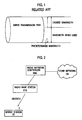
Fig.1 , a mobile communication system described in Patent Document 1 is configured such that the radio base station BTS determines a transfer rate of data transferred from the radio network controller RNC to the radio base station BTS, based on a "bandwidth usage percentage (= 'bandwidth being used' / 'a predetermined bandwidth')" in the wired transmission path. - In the mobile communication system described in Patent Document 1, the "bandwidth usage percentage" increases as a bandwidth being used by a certain mobile station UE increases. Accordingly, this mobile communication system has a problem of lowering the transfer rate at which the radio network controller RNC transfers data directed to the certain mobile station UE to the radio base station BTS even when there is space in, for example, the radio transmission path established between the radio base station BTS and the certain mobile station UE, or a buffer for the certain mobile station UE in the radio base station BTS.
- A first aspect of the present invention is summarized as a radio base station configured to receive data transferred from a radio network controller through a wired transmission path having a predetermined bandwidth, and to transmit the data to a mobile station through a radio transmission path. The radio base station includes: a determiner configured to determine a transfer rate at which the radio network controller transfers the data to the radio base station, based on the predetermined bandwidth, on a bandwidth of the wired transmission path not being used, and on a bandwidth of the wired transmission path being used by the mobile station; and a notifies configured to notify the radio network controller of a determined transfer rate.
- In the first aspect of the present invention, the determiner may be configured to determine the transfer rate, further based on at least one of a communication quality of the radio transmission path, a data discard state in the wired transmission path, a capability of the mobile station and a contract type of the mobile station.
- In the first aspect of the present invention, the wired transmission path is configured with a VP or VC in ATM, and the determiner may be configured to determine the transfer rate in further consideration of a ratio of a length of a header in an ATM cell to a length of a header in RLC-PDU.
- In the first aspect of the present invention, the wired transmission path is configured with an IP transmission path, and the determiner may be configured to determine the transfer rate in further consideration of a ratio of a length of a header in an IP packet cell to a length of a header in RLC-PDU.
- A second aspect of the present invention is summarized as a radio communication method by which a radio base station receives data transferred from a radio network controller though a wired transmission path having a predetermined bandwidth, and transmits the data to a mobile station through a radio transmission path. The method includes the steps of; (a) determining, at the radio base station, a transfer rate at which the radio network controller transfers the data to the radio base station, based on the predetermined bandwidth, on a bandwidth of the wired transmission path not being used, and on a bandwidth of the wired transmission path being used by the mobile station; (b) notifying a determined transfer rate from the radio base station to the radio network controller; and (c) transferring data from the radio network controller to the radio base station through the wired transmission path at a notified transfer rate.
-
-
Fig.1 is a diagram illustrating a problem of a conventional mobile communication system. -
Fig.2 is a diagram showing an overall configuration of a mobile communication system according to a first embodiment of the present invention. -
Fig.3 is a diagram showing a protocol stack in the mobile communication system according to the first embodiment of the present invention. -
Fig.4 is a diagram showing functional blocks of a radio base station according to the first embodiment of the present invention. -
Fig.5 is a diagram illustrating how the radio base station according to the first embodiment of the present invention determines a periodical MAX Iub rate. -
Fig.6 is a sequence diagram showing operations of the mobile communication system according to the first embodiment of the present invention. - With reference to
Figs. 2 to 5 , a description will be given of the configuration of a mobile communication system according to a first embodiment of the present invention. - As shown in
Fig.2 , the mobile communication system according to the present embodiment includes a core network CN, a radio network controller RNC, and a radio base station BTS. - The mobile communication system according to the present embodiment employs a High Speed Downlink Packet Access (HSDPA) scheme. In the HSDPA scheme, Adaptive Modulation and Coding, Hybrid Automatic Repeat reqQuest (H-ARQ), and the like are employed.
- The mobile communication system according to the present embodiment is configured such that the radio base station BTS receives data transferred from the radio network controller RNC through a wired transmission path having a predetermined bandwidth, and transmits the data to a mobile station UE through a High-Speed Downlink Shared CHannel (HS-DSCH).
- In the mobile communication system according to the present embodiment, an ATM transmission path (a Virtual Path (VP) or a Victual Connection (VC) in ATM) or an IP transmission path can be used as the wired transmission path.
-
Fig.3 shows a user-plane protocol stack employed in the mobile communication system according to the present embodiment. - As shown in
Fig.3 , the mobile station UE includes a physical layer PHY, a MAC layer, and an RLC layer, and is connected to the radio base station BTS through a Uu interface. - The radio network controller RNC includes an L1 layer, an L2 layer, an HS-DSCH FP layer, a MAC-d layer, and an RLC layer, and is connected to the radio base station BTS through an Iub interface.
- The radio base station BTS includes a physical layer PHY and a MAC-hs layer which face the mobile station UE, and an L1 layer, an L2 layer, an HS-DSCH FP layer which face the radio network controller RNC.
- In the present embodiment, the flow control is performed on data transferred from the radio network controller RNC to the radio base station BTS in the HS-DSCH FP layers through the Iub interface.
- This flow control can optimally control the rate of RLC-PDU transmitted in the RLC layers.
- Specifically, the radio network controller RNC is configured to transfer the data (RLC-PDU) to the radio base station BTS according to a transfer rate (a capacity allocation (CA) rate) notified of by the radio base station BTS.
- As shown in
Fig.4 , the radio base station BTS according to the present embodiment includes areceiver 11, a MAXFP rate determiner 12, an initial CA rate determiner 13, an initialCA rate notifier 14, a MAXFP rate receiver 21, a Uu rate calculator 22, aUi rate calculator 23, a periodical MAXIub rate calculator 24, a CA rate determiner 25, and aCA rate notifier 26. - The
receiver 11, the MAX FP rate determiner 12, the initial CA rate determiner 13, and the initialCA rate notifier 14 are functions for performing call control processing (AP level). Meanwhile, the MAXFP rate receiver 21, the Uu rate calculator 22, theUi rate calculator 23, the periodical MAXIub rate calculator 24, the CA rate determiner 25, and theCA rate notifier 26 are functions implemented in the HS-DSCH FP layer. - The
receiver 11 is configured to receive a "MAX UE rate", a "MAX DL rate", a "MAX Iur rate" and the like notified of by the radio network controller RNC by means of an NBAP message. - The "MAX UE rate" is a maximum downlink transmission rate in a radio transmission path, which is defined based on the capability of the mobile station UE (UE capability).
- The "MAX DL rate" is a maximum downlink transmission rate in the radio transmission path, which is defined based on the contract type or the like of the mobile station UE.
- Note that it is so configured that the core network CN specifies the "MAX DL rate" by means of a "RAB Assignment Request" being a RANAP message.
- When an Iur interface (which is an interface between the radio base station BTS and the radio network controller RNC) is configured with an ATM transmission path (a VP or a VC in ATM), the "MAX Iur rate" is a maximum downlink transmission rate which is limited according to the transmission bandwidth of the ATM transmission path.
- The MAX
FP rate determiner 12 is configured to determine a "MAX FP rate" based on the "MAX UE rate", the "MAX DL rate", and the "MAX Iur rate", and then notify the MAXFP rate receiver 21 of the determined "MAX FP rate". - Specifically, the MAX
FP rate determiner 12 is configured to take a smallest value among the "MAX UE rate", the "MAX DL rate", and the "MAX Iur rate", and set the smallest value as the MAX FP rate. - The initial
CA rate determiner 13 is configured to determine an initial CA rate based on the "MAX UE rate", the "MAX DL rate", the "MAX Iur rate", and a "MAX Iub rate", and then notify the initialCA rate notifier 14 of the determined initial CA rate. - When the Iub interface is configured with an ATM transmission path (a VP or a VC in ATM), the "MAX Iub rate" is a maximum downlink transmission rate which is limited according to the transmission bandwidth and usage percentage of the ATM transmission path.
- The initial
CA rate notifier 14 is configured to notify the radio network controller RNC of the initial CA rate determined by the initialCA rate determiner 13, by means of an NBAP message or the like. - The MAX
FP rate receiver 21 is configured to notify theCA rate determiner 25 of the "MAX FP rate" notified of by the MAXFP rate determiner 12. - The Uu rate calculator 22 is configured to calculate a transmission rate (MAX Uu rate) at which data can be transmitted in the radio transmission path (Uu interface) between a certain mobile station UE and the radio base station BTS, based on a channel quality indicator (CQI) of that radio transmission path. The Uu rate calculator 22 is configured also to notify the
CA rate determiner 25 of the calculated transmission rate. - As the MAX Uu rate, the Uu rate calculator 22 may alternatively be configured to calculate an average value of the MAX Uu rates obtained in a predetermined period.
- Moreover, the Uu rate calculator 22 may alternatively be configured to calculate an average amount of data held in a buff-er in the MAC-hs layer for each mobile station UE, then calculate a "Uu transmission tolerance coefficient" based on an "(average amount of data held in buffer in MAC-hs layer) / (MAX Uu rate)", and then notify the CA rate determiner 25 of a value obtained by multiplying the "MAX Uu rate" by the "Uu transmission tolerance coefficient."
- The
Ui rate calculator 23 is configured to calculate a transmission rate (MAX Ui rate) at which data can be transmitted in the wired transmission path between the radio base station BTS and the radio network controller RNC, according to a data discard state in the wired transmission path, and notify the CA rate determiner 25 of the calculated transmission rate. - Specifically, the
Ui rate calculator 23 is configured to set the "MAX FP rate" as an initial value of the "MAX Ui rate", and increase or decrease the "MAX Ui rate" depending on whether or not data has been discarded in the wired transmission path within the predetermined period. - When an ATM transmission path is used as the wired transmission path, the periodical MAX
Iub rate calculator 24 is configured to calculate a "periodical MAX Iub rate" based on the following factors and notify theCA rate determiner 25 of the calculated "periodical MAX Iub rate". Specifically as shown inFig. 5 , the "periodical MAX Iub rate" is calculated based on a VP/VC bandwidth set for the ATM transmission path (a predetermined bandwidth, a set VP/VC bandwidth), on a bandwidth of the wired transmission path not being used (unused bandwidth), and on a bandwidth of the wired transmission path being used by the mobile station UE. - For example, the periodical MAX
Iub rate calculator 24 is configured to calculate the "periodical MAX Iub rate" by using the following equation. - MAX {"set VP/VC bandwidth" × "ATM/RLC-PDU rate conversion coefficient" × (100 - "bandwidth usage percentage (%)" - "bandwidth usage percentage offset (%)") + "bandwidth being used by mobile station UE concerned", "set VP/VC bandwidth" × "bandwidth tolerance rate lower limit (%)" × "ATM/RLC-PDU rate conversion coefneient"}
- Here, the "bandwidth usage percentage offset (%)" is a predetermined offset value (%), and the "bandwidth tolerance rate lower limit (%)" is a predetermined lower limit (%).
- In addition, the "ATM/RLC-PDU rate conversion coefficient" is a coefficient calculated based on a ratio of the length of a header in an ATM cell to the length of a header in RLC-PDU. Specifically, the "ATM/RLC-PDU rate conversion coefficient" is a coefficient indicating an efficiency of conversion from an ATM cell to RLC-PDU.
- When an IP transmission path is employed as the wired transmission path, on the other hand, the periodical MAX
Iub rate calculator 24 is configured to calculate the "periodical MAX Iub rate" based on the following factors and notify theCA rate determiner 25 of the calculated "periodical MAX Iub rate". Specifically, as shown inFig.5 , the "periodical MAX Iub rate" is calculated based on a bandwidth set for the IP transmission path (a predetermined bandwidth, a set IP transmission path bandwidth), on a bandwidth of the wired transmission path not being used (unused bandwidth), and on a bandwidth of the wired transmission path being used by the mobile station UE. - For example, the periodical MAX
Iub rate calculator 24 is configured to calculate the "periodical MAX Iub rate" by using the following equation, in this case. - MAX {"set IP transmission path bandwidth" × "IP/RLC-PDU rate conversion coefficient" × (100 - "bandwidth usage percentage (%)" - "bandwidth usage percentage offset (%)") + "bandwidth being used by mobile station UE", "set IP transmission path bandwidth" × "bandwidth tolerance rate lower limit (%)" × "IP/RLC-PDU rate conversion coefficient"}
- Here, the "IP/RLC-PDU rate conversion coefficient" is a coefficient calculated based on a ratio of the length of a header in an IP packet to the length of a header in RLC-PDU. Specifically, the "IP/RLC-PDU rate conversion coefficient" is a coefficient indicating an efficiency of conversion from an IP packet to RLC-PDU.
- The
CA rate determiner 25 is configured to determine a transfer rate (CA rate) of data transferred from the radio network controller RNC to the radio base station BTS, based on the predetermined bandwidth of the wired transmission path (the set VP/VC bandwidth or the set IP transmission path bandwidth), on a bandwidth of the wired transmission path not being used (unused bandwidth), and on a bandwidth of the wired transmission path being used by the mobile station UE, and notify theCA rate notifier 26 of the determined transfer rate. - The
CA rate determiner 25 may be configured to determine the transfer rate (CA rate) based further on at least one of the communication quality in the radio transmission path, the data discard state in the wired transmission path, and the capability of the mobile station UE and a contract type of the mobile station UE. - Furthermore, the
rate determiner 25 may be configured to determine the transfer rate (CA rate) in consideration of the ratio of the length of a header in an ATM cell to the length of a header in RLC-PDU, or of the ratio of the length of a header in an IP packet to the length of a header in RLC-PDU. - Specifically, the
CA rate determiner 25 is configured to determine the CA rate at the predetermined period, based on the "MAX FP rate" notified of by the MAXFP rate receiver 21, the "Uu rate" (or the result of multiplication of the "Uu rate" and the "Uu transmission tolerance coefficient") notified of by the Uu rate calculator 22, the "Ui rate" notified of by theUi rate calculator 23, and the "periodical MAX Iub rate" notified of by the periodical MAXIub rate calculator 24. - For example, the
CA rate determiner 25 may alternatively be configured to take a smallest value among the four values, the "MAX FP rate" notified of by the MAXFP rate receiver 21, the "Uu rate" (or the result of multiplication of the "Uu rate" and the "Uu transmission tolerance coefficient") notified of by the Uu rate calculator 22, the "Ui rate" notified of by theUi rate calculator 23, and the "periodical MAX Iub rate" notified of by the periodical MAXIub rate calculator 24, and set the smallest value as the CA rate at the predetermined period. - The
CA rate notifier 26 is configured to notify the radio network controller RNC of the transfer rate (CA rate) determined by theCA rate determiner 25, by means of an NBAP message or the like. - With reference to
Fig.6 , a description will be given of the operations of the mobile communication system according to the first embodiment of the present invention. - As shown in
Fig.6 , in Step S1001, the radio network controller RNC transmits a "Capacity Request" message to the radio base station BTS. Here, with the "Capacity Request" message, the radio network controller RNC instructs the radio base station BTS of notification of a transfer rate (CA rate) at which the radio network controller RNC transfers data to the radio base station BTS through a wired transmission path. - In Step S1002, in response to the received "Capacity Request" message, the radio base station BTS calculates an initial value of the transfer rate (CA rate) of data directed to a certain mobile station UE (initial CA rate).
- In Step S1003, the radio base station BTS transmits the initial value of the calculated transfer rate (CA rate) of data directed to the mobile station UE (initial CA rate) to the radio network controller RNC.
- Then, the radio base station BTS calculates a transfer rate (CA rate) of data directed to the mobile station UE at a predetermined period, namely, in Step S2001, and transmits the calculated transfer rate (CA rate) of data directed to the mobile station UE to the radio network controller RNC in Step S2002.
- According to the mobile communication system according to the first embodiment of the present invention, the "periodical MAX Iub rate" is calculated in consideration of a bandwidth being used by a mobile station UE concerned, and is used to calculate the CA rate of data directed to that mobile station UE. As a result, the transfer rate (CA rate) at which the radio network controller RNC transfers data directed to the mobile station UE to the radio base station BTS is not lowered when there is space in, for example, the radio transmission path established between the radio base station BTS and the certain mobile station UE, or the buffer for the certain mobile station UE in the radio base station BTS (a buffer in the MAC·hs layer).
- Note that the above-described operations of the mobile station UE, the radio base station BTS, and the radio network controller RNC may be implemented by hardware, by a software module executed by a processor, or by a combination of both.
- The software module may be provided in a storage medium of any form including a random access memory (RAM), a flash memory, a read-only memory (ROM), an erasable programmable ROM (EPROM), an electronically erasable programmable ROM (EEPROM), a register, a hard disk, a removable disk, and a CD-ROM.
- The storage medium is connected to the processor so that the processor can read and write information from and onto the storage medium. The storage medium may be integrated with the processor. In addition, the storage medium and the processor may be provided in an ASIC. The ASIC may be provided in the mobile station UE, the radio base station BTS, and the radio network controller RNC. Further, the storage medium and the processor may be in the mobile station UE, the radio base station BTS, and the radio network controller RNC as a discrete component.
- The present invention has been described above in detail by using the above embodiment. However, it is apparent for those skilled in the art that the present invention is not limited by the embodiment described in this specification. The present invention can be implemented as amended or modified forms without departing from the spirit and scope of the present invention, which is defined by the description in "What is claimed is." The description of this specification has been given to illustrate the present invention, and therefore is not intended to limit the present invention.
Claims (5)
- A radio base station configured to receive data transferred from a radio network controller through a wired transmission path having a predetermined bandwidth, and to transmit the data to a mobile station through a radio transmission path, the radio base station comprising:a determiner configured to determine a transfer rate at which the radio network controller transfers the data to the radio base station, based on the predetermined bandwidth, on a bandwidth of the wired transmission path not being used, and on a bandwidth of the wired transmission path being used by the mobile station; anda notifier configured to notify the radio network controller of a determined transfer rate.
- The radio base station according to claim 1, wherein
the determiner determines the transfer rate, further based on at least one of a communication quality of the radio transmission path, a data discard state in the wired transmission path, a capability of the mobile station and a contract type of the mobile station. - The radio base station according to claim 1, wherein
the wired transmission path is configured with a VP or VC in ATM, and
the determiner determines the transfer rate in further consideration of a ratio of a length of a header in an ATM cell to a length of a header in RLC-PDU. - The radio base station according to claim 1, wherein
the wired transmission path is configured with an IP transmission path, and
the determiner determines the transfer rate in further consideration of a ratio of a length of a header in an IP packet cell to a length of a header in RLC-PDU. - A mobile communication method by which a radio base station receives data transferred from a radio network controller though a wired transmission path having a predetermined bandwidth, and transmits the data to a mobile station through a radio transmission path, the method comprising the steps of:determining, at the radio base station, a transfer rate at which the radio network controller transfers the data to the radio base station, based on the predetermined bandwidth, on a bandwidth of the wired transmission path not being used, and on a bandwidth of the wired transmission path being used by the mobile station;notifying a determined transfer rate from the radio base station to the radio network controller; andtransferring data from the radio network controller to the radio base station through the wired transmission path at a notified transfer rate.
Applications Claiming Priority (1)
| Application Number | Priority Date | Filing Date | Title |
|---|---|---|---|
| JP2008119861A JP5052404B2 (en) | 2008-05-01 | 2008-05-01 | Radio base station and mobile communication method |
Publications (2)
| Publication Number | Publication Date |
|---|---|
| EP2114038A1 true EP2114038A1 (en) | 2009-11-04 |
| EP2114038B1 EP2114038B1 (en) | 2011-06-08 |
Family
ID=40873764
Family Applications (1)
| Application Number | Title | Priority Date | Filing Date |
|---|---|---|---|
| EP20090006020 Not-in-force EP2114038B1 (en) | 2008-05-01 | 2009-04-30 | Radio base station and mobile communication method |
Country Status (5)
| Country | Link |
|---|---|
| US (1) | US8422440B2 (en) |
| EP (1) | EP2114038B1 (en) |
| JP (1) | JP5052404B2 (en) |
| CN (1) | CN101572966B (en) |
| AT (1) | ATE512530T1 (en) |
Cited By (1)
| Publication number | Priority date | Publication date | Assignee | Title |
|---|---|---|---|---|
| WO2015121941A1 (en) * | 2014-02-13 | 2015-08-20 | 株式会社日立製作所 | Rate control device and base station, and wireless communication system |
Families Citing this family (4)
| Publication number | Priority date | Publication date | Assignee | Title |
|---|---|---|---|---|
| US8718666B1 (en) * | 2012-01-23 | 2014-05-06 | Sprint Communications Company L.P. | Controlling resource utilization |
| WO2013125994A1 (en) * | 2012-02-22 | 2013-08-29 | Telefonaktiebolaget L M Ericsson (Publ) | Measurement based qos adaptation |
| JP2014229985A (en) * | 2013-05-20 | 2014-12-08 | 富士通株式会社 | Communication system, communication control method, mobile station, and control device |
| WO2016042686A1 (en) * | 2014-09-19 | 2016-03-24 | 日本電気株式会社 | Data transmission control device and control method |
Citations (4)
| Publication number | Priority date | Publication date | Assignee | Title |
|---|---|---|---|---|
| EP1331768A1 (en) * | 2002-01-25 | 2003-07-30 | Lucent Technologies Inc. | Rate control system and method for a link within a wireless communications system |
| JP2005286786A (en) | 2004-03-30 | 2005-10-13 | Matsushita Electric Ind Co Ltd | Radio base station apparatus and data transfer control method |
| US20060126509A1 (en) * | 2004-12-09 | 2006-06-15 | Firas Abi-Nassif | Traffic management in a wireless data network |
| EP1672845A1 (en) * | 2004-12-15 | 2006-06-21 | Nec Corporation | Wireless base station device and rate control method thereof |
Family Cites Families (7)
| Publication number | Priority date | Publication date | Assignee | Title |
|---|---|---|---|---|
| JP3892682B2 (en) * | 2001-06-18 | 2007-03-14 | 株式会社エヌ・ティ・ティ・ドコモ | Packet transmission method, base station and mobile station |
| JP4176576B2 (en) | 2003-08-01 | 2008-11-05 | 株式会社エヌ・ティ・ティ・ドコモ | Data inflow control method, base station and control station |
| ES2353611T3 (en) * | 2005-01-11 | 2011-03-03 | Ntt Docomo, Inc. | RADIO RESOURCE MANAGEMENT PROCEDURE, RADIO BASE STATION AND RADIO STATION CONTROLLER. |
| JP4668733B2 (en) * | 2005-08-19 | 2011-04-13 | 株式会社エヌ・ティ・ティ・ドコモ | Transmission rate control method and mobile station |
| CN100551119C (en) * | 2005-11-11 | 2009-10-14 | 上海贝尔阿尔卡特股份有限公司 | The method and the base station that are used for allocated bandwidth in the wireless single-hop self-return network |
| JP2007259031A (en) | 2006-03-23 | 2007-10-04 | Fujitsu Ltd | Mobile communication system and flow control method |
| US7948962B2 (en) * | 2007-08-31 | 2011-05-24 | Wireless Technology Solutions Llc | Cellular communication system, apparatus and method for management of backhaul resources |
-
2008
- 2008-05-01 JP JP2008119861A patent/JP5052404B2/en not_active Expired - Fee Related
-
2009
- 2009-04-27 US US12/430,363 patent/US8422440B2/en not_active Expired - Fee Related
- 2009-04-29 CN CN200910137837XA patent/CN101572966B/en not_active Expired - Fee Related
- 2009-04-30 EP EP20090006020 patent/EP2114038B1/en not_active Not-in-force
- 2009-04-30 AT AT09006020T patent/ATE512530T1/en not_active IP Right Cessation
Patent Citations (4)
| Publication number | Priority date | Publication date | Assignee | Title |
|---|---|---|---|---|
| EP1331768A1 (en) * | 2002-01-25 | 2003-07-30 | Lucent Technologies Inc. | Rate control system and method for a link within a wireless communications system |
| JP2005286786A (en) | 2004-03-30 | 2005-10-13 | Matsushita Electric Ind Co Ltd | Radio base station apparatus and data transfer control method |
| US20060126509A1 (en) * | 2004-12-09 | 2006-06-15 | Firas Abi-Nassif | Traffic management in a wireless data network |
| EP1672845A1 (en) * | 2004-12-15 | 2006-06-21 | Nec Corporation | Wireless base station device and rate control method thereof |
Non-Patent Citations (2)
| Title |
|---|
| "Universal Mobile Telecommunications System (UMTS); Iub/Iur congestion control (3GPP TR 25.902 version 7.1.0 Release 7); ETSI TR 125 902", ETSI STANDARDS, LIS, SOPHIA ANTIPOLIS CEDEX, FRANCE, vol. 3-R3, no. V7.1.0, 1 March 2007 (2007-03-01), XP014037494, ISSN: 0000-0001 * |
| SZILVESZTER NADAS ET AL: "Providing Congestion Control in the Iub Transport Network for HSDPA", GLOBAL TELECOMMUNICATIONS CONFERENCE, 2007. GLOBECOM '07. IEEE, IEEE, PISCATAWAY, NJ, USA, 1 November 2007 (2007-11-01), pages 5293 - 5297, XP031196931, ISBN: 978-1-4244-1042-2 * |
Cited By (1)
| Publication number | Priority date | Publication date | Assignee | Title |
|---|---|---|---|---|
| WO2015121941A1 (en) * | 2014-02-13 | 2015-08-20 | 株式会社日立製作所 | Rate control device and base station, and wireless communication system |
Also Published As
| Publication number | Publication date |
|---|---|
| JP2009272761A (en) | 2009-11-19 |
| EP2114038B1 (en) | 2011-06-08 |
| CN101572966B (en) | 2011-12-21 |
| ATE512530T1 (en) | 2011-06-15 |
| CN101572966A (en) | 2009-11-04 |
| US20090274108A1 (en) | 2009-11-05 |
| JP5052404B2 (en) | 2012-10-17 |
| US8422440B2 (en) | 2013-04-16 |
Similar Documents
| Publication | Publication Date | Title |
|---|---|---|
| JP5113848B2 (en) | How to support quality of service for the lifetime of a connection | |
| EP1797659B1 (en) | Slow mac-e for autonomous transmission in high speed uplink packet access (hsupa) along with service specific transmission time control | |
| JP4971444B2 (en) | High-speed downlink packet access (HSDPA) channel coverage improvement | |
| EP1655907A1 (en) | Method and apparatus for scheduling uplink data transmission for a mobile station in soft handover region in a mobile communication system | |
| KR20140116556A (en) | Method and apparatus for generating a radio link control protocol data unit for multi-carrier operation | |
| KR101406586B1 (en) | Method and terminal for setting a happy bit on an uplink enhanced control channel | |
| EP1677457B1 (en) | Method and apparatus for signalling control information of uplink packet data service in mobile telecommunication system | |
| US20060050723A1 (en) | Radio system, base station, controller, and method of controlling data transmission | |
| EP2114038A1 (en) | Radio base station and mobile communication method | |
| CN101099408B (en) | Transmission rate control method, mobile station, radio base station, and wireless line control station | |
| CA2618897A1 (en) | Flow control in umts | |
| CN101170389B (en) | Method for selecting first transmission block size of protocol data unit at radio link control layer | |
| CN101156484B (en) | Transmission rate control method, mobile station, and wireless line controller | |
| CN101494524B (en) | Transmission rate control method and radio base station | |
| JP4999724B2 (en) | Mobile communication method, mobile communication system, and radio base station | |
| CN101409924A (en) | Radio communication system, radio communication method and base station | |
| WO2010095576A1 (en) | Wireless communication system, radio base station and wireless communication method | |
| CN101103613A (en) | Transmission rate control method, mobile station, and radio network controller | |
| CN101123574A (en) | How to configure the size of the non-acknowledged mode reordering cache |
Legal Events
| Date | Code | Title | Description |
|---|---|---|---|
| PUAI | Public reference made under article 153(3) epc to a published international application that has entered the european phase |
Free format text: ORIGINAL CODE: 0009012 |
|
| 17P | Request for examination filed |
Effective date: 20090430 |
|
| AK | Designated contracting states |
Kind code of ref document: A1 Designated state(s): AT BE BG CH CY CZ DE DK EE ES FI FR GB GR HR HU IE IS IT LI LT LU LV MC MK MT NL NO PL PT RO SE SI SK TR |
|
| 17Q | First examination report despatched |
Effective date: 20091222 |
|
| GRAP | Despatch of communication of intention to grant a patent |
Free format text: ORIGINAL CODE: EPIDOSNIGR1 |
|
| GRAS | Grant fee paid |
Free format text: ORIGINAL CODE: EPIDOSNIGR3 |
|
| GRAA | (expected) grant |
Free format text: ORIGINAL CODE: 0009210 |
|
| AK | Designated contracting states |
Kind code of ref document: B1 Designated state(s): AT BE BG CH CY CZ DE DK EE ES FI FR GB GR HR HU IE IS IT LI LT LU LV MC MK MT NL NO PL PT RO SE SI SK TR |
|
| REG | Reference to a national code |
Ref country code: GB Ref legal event code: FG4D |
|
| REG | Reference to a national code |
Ref country code: CH Ref legal event code: EP |
|
| REG | Reference to a national code |
Ref country code: IE Ref legal event code: FG4D |
|
| REG | Reference to a national code |
Ref country code: DE Ref legal event code: R096 Ref document number: 602009001452 Country of ref document: DE Effective date: 20110721 |
|
| REG | Reference to a national code |
Ref country code: NL Ref legal event code: VDEP Effective date: 20110608 |
|
| PG25 | Lapsed in a contracting state [announced via postgrant information from national office to epo] |
Ref country code: SE Free format text: LAPSE BECAUSE OF FAILURE TO SUBMIT A TRANSLATION OF THE DESCRIPTION OR TO PAY THE FEE WITHIN THE PRESCRIBED TIME-LIMIT Effective date: 20110608 Ref country code: LT Free format text: LAPSE BECAUSE OF FAILURE TO SUBMIT A TRANSLATION OF THE DESCRIPTION OR TO PAY THE FEE WITHIN THE PRESCRIBED TIME-LIMIT Effective date: 20110608 Ref country code: NO Free format text: LAPSE BECAUSE OF FAILURE TO SUBMIT A TRANSLATION OF THE DESCRIPTION OR TO PAY THE FEE WITHIN THE PRESCRIBED TIME-LIMIT Effective date: 20110908 Ref country code: HR Free format text: LAPSE BECAUSE OF FAILURE TO SUBMIT A TRANSLATION OF THE DESCRIPTION OR TO PAY THE FEE WITHIN THE PRESCRIBED TIME-LIMIT Effective date: 20110608 |
|
| PG25 | Lapsed in a contracting state [announced via postgrant information from national office to epo] |
Ref country code: AT Free format text: LAPSE BECAUSE OF FAILURE TO SUBMIT A TRANSLATION OF THE DESCRIPTION OR TO PAY THE FEE WITHIN THE PRESCRIBED TIME-LIMIT Effective date: 20110608 Ref country code: GR Free format text: LAPSE BECAUSE OF FAILURE TO SUBMIT A TRANSLATION OF THE DESCRIPTION OR TO PAY THE FEE WITHIN THE PRESCRIBED TIME-LIMIT Effective date: 20110909 Ref country code: LV Free format text: LAPSE BECAUSE OF FAILURE TO SUBMIT A TRANSLATION OF THE DESCRIPTION OR TO PAY THE FEE WITHIN THE PRESCRIBED TIME-LIMIT Effective date: 20110608 Ref country code: CY Free format text: LAPSE BECAUSE OF FAILURE TO SUBMIT A TRANSLATION OF THE DESCRIPTION OR TO PAY THE FEE WITHIN THE PRESCRIBED TIME-LIMIT Effective date: 20110608 Ref country code: ES Free format text: LAPSE BECAUSE OF FAILURE TO SUBMIT A TRANSLATION OF THE DESCRIPTION OR TO PAY THE FEE WITHIN THE PRESCRIBED TIME-LIMIT Effective date: 20110919 Ref country code: FI Free format text: LAPSE BECAUSE OF FAILURE TO SUBMIT A TRANSLATION OF THE DESCRIPTION OR TO PAY THE FEE WITHIN THE PRESCRIBED TIME-LIMIT Effective date: 20110608 Ref country code: SI Free format text: LAPSE BECAUSE OF FAILURE TO SUBMIT A TRANSLATION OF THE DESCRIPTION OR TO PAY THE FEE WITHIN THE PRESCRIBED TIME-LIMIT Effective date: 20110608 |
|
| PG25 | Lapsed in a contracting state [announced via postgrant information from national office to epo] |
Ref country code: BE Free format text: LAPSE BECAUSE OF FAILURE TO SUBMIT A TRANSLATION OF THE DESCRIPTION OR TO PAY THE FEE WITHIN THE PRESCRIBED TIME-LIMIT Effective date: 20110608 Ref country code: NL Free format text: LAPSE BECAUSE OF FAILURE TO SUBMIT A TRANSLATION OF THE DESCRIPTION OR TO PAY THE FEE WITHIN THE PRESCRIBED TIME-LIMIT Effective date: 20110608 |
|
| PG25 | Lapsed in a contracting state [announced via postgrant information from national office to epo] |
Ref country code: CZ Free format text: LAPSE BECAUSE OF FAILURE TO SUBMIT A TRANSLATION OF THE DESCRIPTION OR TO PAY THE FEE WITHIN THE PRESCRIBED TIME-LIMIT Effective date: 20110608 Ref country code: PT Free format text: LAPSE BECAUSE OF FAILURE TO SUBMIT A TRANSLATION OF THE DESCRIPTION OR TO PAY THE FEE WITHIN THE PRESCRIBED TIME-LIMIT Effective date: 20111010 Ref country code: EE Free format text: LAPSE BECAUSE OF FAILURE TO SUBMIT A TRANSLATION OF THE DESCRIPTION OR TO PAY THE FEE WITHIN THE PRESCRIBED TIME-LIMIT Effective date: 20110608 Ref country code: IS Free format text: LAPSE BECAUSE OF FAILURE TO SUBMIT A TRANSLATION OF THE DESCRIPTION OR TO PAY THE FEE WITHIN THE PRESCRIBED TIME-LIMIT Effective date: 20111008 |
|
| PG25 | Lapsed in a contracting state [announced via postgrant information from national office to epo] |
Ref country code: SK Free format text: LAPSE BECAUSE OF FAILURE TO SUBMIT A TRANSLATION OF THE DESCRIPTION OR TO PAY THE FEE WITHIN THE PRESCRIBED TIME-LIMIT Effective date: 20110608 Ref country code: PL Free format text: LAPSE BECAUSE OF FAILURE TO SUBMIT A TRANSLATION OF THE DESCRIPTION OR TO PAY THE FEE WITHIN THE PRESCRIBED TIME-LIMIT Effective date: 20110608 Ref country code: RO Free format text: LAPSE BECAUSE OF FAILURE TO SUBMIT A TRANSLATION OF THE DESCRIPTION OR TO PAY THE FEE WITHIN THE PRESCRIBED TIME-LIMIT Effective date: 20110608 |
|
| PLBE | No opposition filed within time limit |
Free format text: ORIGINAL CODE: 0009261 |
|
| STAA | Information on the status of an ep patent application or granted ep patent |
Free format text: STATUS: NO OPPOSITION FILED WITHIN TIME LIMIT |
|
| 26N | No opposition filed |
Effective date: 20120309 |
|
| PG25 | Lapsed in a contracting state [announced via postgrant information from national office to epo] |
Ref country code: IT Free format text: LAPSE BECAUSE OF FAILURE TO SUBMIT A TRANSLATION OF THE DESCRIPTION OR TO PAY THE FEE WITHIN THE PRESCRIBED TIME-LIMIT Effective date: 20110608 |
|
| PG25 | Lapsed in a contracting state [announced via postgrant information from national office to epo] |
Ref country code: DK Free format text: LAPSE BECAUSE OF FAILURE TO SUBMIT A TRANSLATION OF THE DESCRIPTION OR TO PAY THE FEE WITHIN THE PRESCRIBED TIME-LIMIT Effective date: 20110608 |
|
| REG | Reference to a national code |
Ref country code: DE Ref legal event code: R097 Ref document number: 602009001452 Country of ref document: DE Effective date: 20120309 |
|
| PG25 | Lapsed in a contracting state [announced via postgrant information from national office to epo] |
Ref country code: MC Free format text: LAPSE BECAUSE OF NON-PAYMENT OF DUE FEES Effective date: 20120430 |
|
| REG | Reference to a national code |
Ref country code: FR Ref legal event code: ST Effective date: 20121228 |
|
| PG25 | Lapsed in a contracting state [announced via postgrant information from national office to epo] |
Ref country code: MK Free format text: LAPSE BECAUSE OF FAILURE TO SUBMIT A TRANSLATION OF THE DESCRIPTION OR TO PAY THE FEE WITHIN THE PRESCRIBED TIME-LIMIT Effective date: 20110608 Ref country code: FR Free format text: LAPSE BECAUSE OF NON-PAYMENT OF DUE FEES Effective date: 20120430 |
|
| PG25 | Lapsed in a contracting state [announced via postgrant information from national office to epo] |
Ref country code: IE Free format text: LAPSE BECAUSE OF NON-PAYMENT OF DUE FEES Effective date: 20120430 |
|
| PG25 | Lapsed in a contracting state [announced via postgrant information from national office to epo] |
Ref country code: BG Free format text: LAPSE BECAUSE OF FAILURE TO SUBMIT A TRANSLATION OF THE DESCRIPTION OR TO PAY THE FEE WITHIN THE PRESCRIBED TIME-LIMIT Effective date: 20110908 |
|
| PG25 | Lapsed in a contracting state [announced via postgrant information from national office to epo] |
Ref country code: MT Free format text: LAPSE BECAUSE OF FAILURE TO SUBMIT A TRANSLATION OF THE DESCRIPTION OR TO PAY THE FEE WITHIN THE PRESCRIBED TIME-LIMIT Effective date: 20110608 |
|
| REG | Reference to a national code |
Ref country code: CH Ref legal event code: PL |
|
| PG25 | Lapsed in a contracting state [announced via postgrant information from national office to epo] |
Ref country code: CH Free format text: LAPSE BECAUSE OF NON-PAYMENT OF DUE FEES Effective date: 20130430 Ref country code: LI Free format text: LAPSE BECAUSE OF NON-PAYMENT OF DUE FEES Effective date: 20130430 |
|
| PG25 | Lapsed in a contracting state [announced via postgrant information from national office to epo] |
Ref country code: TR Free format text: LAPSE BECAUSE OF FAILURE TO SUBMIT A TRANSLATION OF THE DESCRIPTION OR TO PAY THE FEE WITHIN THE PRESCRIBED TIME-LIMIT Effective date: 20110608 |
|
| PG25 | Lapsed in a contracting state [announced via postgrant information from national office to epo] |
Ref country code: LU Free format text: LAPSE BECAUSE OF NON-PAYMENT OF DUE FEES Effective date: 20120430 |
|
| PG25 | Lapsed in a contracting state [announced via postgrant information from national office to epo] |
Ref country code: HU Free format text: LAPSE BECAUSE OF FAILURE TO SUBMIT A TRANSLATION OF THE DESCRIPTION OR TO PAY THE FEE WITHIN THE PRESCRIBED TIME-LIMIT Effective date: 20090430 |
|
| PGFP | Annual fee paid to national office [announced via postgrant information from national office to epo] |
Ref country code: DE Payment date: 20150422 Year of fee payment: 7 Ref country code: GB Payment date: 20150429 Year of fee payment: 7 |
|
| REG | Reference to a national code |
Ref country code: DE Ref legal event code: R119 Ref document number: 602009001452 Country of ref document: DE |
|
| GBPC | Gb: european patent ceased through non-payment of renewal fee |
Effective date: 20160430 |
|
| PG25 | Lapsed in a contracting state [announced via postgrant information from national office to epo] |
Ref country code: GB Free format text: LAPSE BECAUSE OF NON-PAYMENT OF DUE FEES Effective date: 20160430 Ref country code: DE Free format text: LAPSE BECAUSE OF NON-PAYMENT OF DUE FEES Effective date: 20161101 |