EP2113729A1 - Engine-driven heat pump - Google Patents
Engine-driven heat pump Download PDFInfo
- Publication number
- EP2113729A1 EP2113729A1 EP08711642A EP08711642A EP2113729A1 EP 2113729 A1 EP2113729 A1 EP 2113729A1 EP 08711642 A EP08711642 A EP 08711642A EP 08711642 A EP08711642 A EP 08711642A EP 2113729 A1 EP2113729 A1 EP 2113729A1
- Authority
- EP
- European Patent Office
- Prior art keywords
- engine
- floorboard
- heat pump
- driven heat
- refrigerating machine
- Prior art date
- Legal status (The legal status is an assumption and is not a legal conclusion. Google has not performed a legal analysis and makes no representation as to the accuracy of the status listed.)
- Granted
Links
Images

Classifications
-
- F—MECHANICAL ENGINEERING; LIGHTING; HEATING; WEAPONS; BLASTING
- F24—HEATING; RANGES; VENTILATING
- F24F—AIR-CONDITIONING; AIR-HUMIDIFICATION; VENTILATION; USE OF AIR CURRENTS FOR SCREENING
- F24F5/00—Air-conditioning systems or apparatus not covered by F24F1/00 or F24F3/00, e.g. using solar heat or combined with household units such as an oven or water heater
-
- F—MECHANICAL ENGINEERING; LIGHTING; HEATING; WEAPONS; BLASTING
- F25—REFRIGERATION OR COOLING; COMBINED HEATING AND REFRIGERATION SYSTEMS; HEAT PUMP SYSTEMS; MANUFACTURE OR STORAGE OF ICE; LIQUEFACTION SOLIDIFICATION OF GASES
- F25B—REFRIGERATION MACHINES, PLANTS OR SYSTEMS; COMBINED HEATING AND REFRIGERATION SYSTEMS; HEAT PUMP SYSTEMS
- F25B27/00—Machines, plants or systems, using particular sources of energy
-
- F—MECHANICAL ENGINEERING; LIGHTING; HEATING; WEAPONS; BLASTING
- F24—HEATING; RANGES; VENTILATING
- F24F—AIR-CONDITIONING; AIR-HUMIDIFICATION; VENTILATION; USE OF AIR CURRENTS FOR SCREENING
- F24F1/00—Room units for air-conditioning, e.g. separate or self-contained units or units receiving primary air from a central station
- F24F1/06—Separate outdoor units, e.g. outdoor unit to be linked to a separate room comprising a compressor and a heat exchanger
- F24F1/08—Compressors specially adapted for separate outdoor units
- F24F1/12—Vibration or noise prevention thereof
-
- F—MECHANICAL ENGINEERING; LIGHTING; HEATING; WEAPONS; BLASTING
- F24—HEATING; RANGES; VENTILATING
- F24F—AIR-CONDITIONING; AIR-HUMIDIFICATION; VENTILATION; USE OF AIR CURRENTS FOR SCREENING
- F24F1/00—Room units for air-conditioning, e.g. separate or self-contained units or units receiving primary air from a central station
- F24F1/06—Separate outdoor units, e.g. outdoor unit to be linked to a separate room comprising a compressor and a heat exchanger
- F24F1/36—Drip trays for outdoor units
Definitions
- the outdoor fan 12 is constructed so as to inhale the ambient air from the front or the back side thereof, to exchange the heat of it by the outdoor heat exchanger 11 and to ventilate it out of the upper surface thereof. Due to the ventilating construction, the heat of the radiator is also exchanged.
- this ventilating construction is a construction of the form referred to as top-blown type commonly used for a large-size engine-driven heat pump.
Landscapes
- Engineering & Computer Science (AREA)
- Mechanical Engineering (AREA)
- General Engineering & Computer Science (AREA)
- Chemical & Material Sciences (AREA)
- Combustion & Propulsion (AREA)
- Physics & Mathematics (AREA)
- Thermal Sciences (AREA)
- Life Sciences & Earth Sciences (AREA)
- Sustainable Development (AREA)
- Other Air-Conditioning Systems (AREA)
- Compressor (AREA)
- Details Of Reciprocating Pumps (AREA)
Abstract
Description
- The present invention relates to a construction of a floorboard of an engine-driven heat pump having an engine driving a compressor and a receiver accommodating a refrigerant liquid.
- Conventionally, there is well-known an engine-driven heat pump constructed so as to drive a compressor by an engine, as one of an air-conditioning system.
There may be occasions when a damage to an oil seal portion in a power transmitting portion (a flywheel or a drive shaft) from an engine to a compressor or the like result in flying an engine oil in all directions, or in leaking the engine oil out of a pipe or the like of the engine. Therefore, various novel ideas has been executed, so as to prevent the engine oil from leaking out of the system and to collect the engine oil at that time, in a construction of a bottom face of an equipment compartment. - For example,
JP 2003-279077 - However, the bottom panel of the engine-driven heat pump described in
JP 2003-279077
The engine would be associated with a noise due to driving fluctuation. For this reason, when the entire bottom face of the engine-driven heat pump is made up of one bottom panel, the noise having large amplitude may be sometimes generated.
Consequently, problems to be solved by the present invention are to provide a construction of a floor board in an engine-driven heat pump capable of preventing the leaking of the engine oil, of draining away the condensate water due to the dropwise condensation in the refrigeration machine and of reducing the noise due to the engine vibration as a vibratory source, using a simple construction. - In an engine-driven heat pump of the present invention, comprising of an engine for driving a compressor and a receiver for accommodating a refrigerant liquid, a floorboard for a refrigerating machine on which the receiver is provided and an engine mounting floorboard on which the engine is provided are comprised as different members.
Accordingly, because only the engine as a vibratory source is installed on the engine mounting floorboard, an amplitude can be restrained and a noise can be reduced, compared to the case when the whole floorboard of the equipment compartment is vibrated by the engine.
Since the floorboard for the refrigerating machine and the engine mounting floorboard are comprised as different members, the collection of the condensate water due to the dropwise condensation and that of the engine oil when it is leaked can be separately performed. - In the present invention, the floorboard for the refrigerating machine is formed so that a drain outlet is provided thereon and a sidewall is provided on the peripheral border thereof, and the engine mounting floorboard is formed so that a sidewall is provided on the peripheral border thereof.
Accordingly, the condensate water generated in the equipment compartment can be assuredly drained away to the outside of the engine-driven heat pump, while as the engine mounting floorboard is interrupted from the outside thereof without an opening portion, when the engine oil is leaked, the leaked engine oil can be prevented from escaping to the outside of the engine-driven heat pump. - In the present invention, a plate-like member for introducing the engine oil flied in all directions from the engine on the engine mounting floorboard is provided, adjacent to a power transmitting portion from the engine to the compressor.
Accordingly, for example, even when the engine oil is flied in all directions from the end portion of the engine output shaft, the engine oil can be fallen down to the engine mounting floorboard. Therefore, the engine oil flied in all directions can be prevented from escaping to the outside of the engine-driven heat pump. -
-
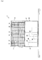
Fig. 1 is an elevational view illustrating a whole construction of an engine-driven heat pump according to an embodiment of the present invention. -
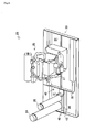
Fig. 2 is a perspective view illustrating arrangements of an engine, a receiver and an oil separator in an equipment compartment according to an embodiment of the present invention. -
Fig. 3 is a partial sectional view illustrating a cross-section of a flywheel portion of the engine according to an embodiment of the present invention. - An engine-driven heat pump 1 according to the present invention will be briefly described, with reference to
Fig. 1 . As illustrated inFig. 1 , the engine-driven heat pump 1 comprises twoequipment chambers heat exchanging chamber 10, and the lower equipment chamber is anequipment compartment 20. Theheat exchanging chamber 10 is constructed so as to ventilate an ambient air for the heat exchange in anoutdoor heat exchanger 11. Theheat exchanging chamber 10 includesoutdoor heat exchangers 11, a radiator (not shown),outdoor fans 12 andmotors 13 foroutdoor fans 12 or the like. Theoutdoor heat exchanger 11 is disposed on the front and the back sides of theheat exchanging chamber 10. Theoutdoor fan 12 is constructed so as to inhale the ambient air from the front or the back side thereof, to exchange the heat of it by theoutdoor heat exchanger 11 and to ventilate it out of the upper surface thereof. Due to the ventilating construction, the heat of the radiator is also exchanged. In this regard, this ventilating construction is a construction of the form referred to as top-blown type commonly used for a large-size engine-driven heat pump. - Meanwhile, the
equipment compartment 20 is a substantially hermetic type equipment compartment communicating with the exterior portion thereof only through a ventilating hole (not shown), an engine intake pipe (not shown) and an exhaust pipe (not shown). Main equipments in the engine-driven heat pump 1, such as an engine system equipment, a refrigerating machine and an electric machinery box (not shown), are disposed in theequipment compartment 20. Anengine 22, peripheral equipments or the like are disposed therein, as the engine system equipment. Acompressor 23, anoil separator 25, areceiver 24 or the like are disposed therein, as the refrigerating machine. Theequipment compartment 20 is covered around the sides thereof withouter plates 21. Incidentally, aswash plate 50 will be described in greater detail later. - A construction of a
floorboard 40 for the refrigerating machine will be described in detail, with reference toFig. 2 . In this regard,Fig. 2 illustrates only anengine 22, thereceiver 24 and theoil separator 25 in theequipment compartment 20, and theouter plates 21 and theswash plates 50 are omitted, so as to explain it simply. As illustrated inFig. 2 , thefloorboard 40 for the refrigerating machine is formed so as to be a dish-shaped or a box-shaped configuration, having asidewall 43 on the periphery thereof. The height of thesidewall 43, which is not especially limited in the present embodiment, is enough at the level of 50 mm to 100 mm. Thefloorboard 40 for the refrigerating machine is provided on the bottom face thereof with adrain outlet 42. Thefloorboard 40 for the refrigerating machine is communicated with the outside of the engine-driven heat pump 1 via thedrain outlet 42. Thefloorboard 40 for the refrigerating machine is disposed on the output side of the engine 22 (i.e., on the side of the compressor 23) in the width direction of the engine-driven heat pump 1, and approximately at the middle in the depth direction thereof. Thereceiver 24 and theoil separator 25 attached to amounting stage 45 are installed on thefloorboard 40 for the refrigerating machine. - Due to the above-mentioned construction, the following effect can be achieved. Some of the refrigerating machines disposed at the
equipment compartment 20 become low-temperature during operation For example, thereceiver 24 causes the dropwise condensation on the surface thereof due to moisture in the air, because the refrigerant liquid accommodated therein during operation becomes low-temperature. Therefore, the dropwise condensation is dropped down and collected, so that it is accumulated as the condensate water on the bottom face of theequipment compartment 20. The same type of phenomenon occurs at liquid pipes on the periphery of thereceiver 24. Thefloorboard 40 for the refrigerating machine is constructed so that it can collects these condensate water and assuredly drain away them from thedrain outlet 42 to the outside of the engine-driven heat pump 1. - A construction of an
engine mounting floorboard 30 will be also described in detail, with reference toFig. 2 . As illustrated inFig. 2 , theengine mounting floorboard 30 is formed so as to be a dish-shaped or a box-shaped configuration, having asidewall 33 on the periphery thereof. The height of thesidewall 33, which is not especially limited in the present embodiment, is substantially the same height as thefloorboard 40 for the refrigerating machine. Abottom face 31 of the engine mounting floorboard do not have an opening portion, an aperture or the like, so that theengine mounting floorboard 30 is interrupted from thefloorboard 40 for the refrigerating machine and the floorboards of the other portions of theequipment compartment 20. Theengine mounting floorboard 30 is disposed on the right side from an anterior view in the width direction of the engine-driven heat pump 1 and at the substantially middle portion in the depth direction thereof. Theengine 22 attached to an engine mount 51 (seeFig. 3 ) is installed on theengine mounting floorboard 30. - Due to the above-described construction, the following effect can be achieved. There may be occasions when a damage or the like to an oil seal portion in a
flywheel 27 of theengine 22 or a drive shaft from theengine 22 to thecompressor 23 result in flying the engine oil in all directions, or in leaking the engine oil out of a pipe or the like of theengine 22. Therefore, because theengine mounting floorboard 30 is formed so as to be a dish-shaped or a box-shaped configuration, the engine oil can be collected only by theengine mounting floorboard 30, thereby preventing the engine oil from leaking out of the outside of theengine mounting floorboard 30, if perchance the engine oil is leaked. - The following effects can be also obtained. That is to say, the
floorboard 40 for the refrigerating machine and theengine mounting floorboard 30 are separately comprised, whereby the discharge of the condensate water due to the dropwise condensation, and the collection of the engine oil while it is leaked can be performed respectively. Thefloorboard 40 for the refrigerating machine and theengine mounting floorboard 30 are easily manufacturable, as they are simply formed so as to be a dish-shaped or a box-shaped configuration.
Because theengine 22 is installed only on theengine mounting floorboard 30, the amplitude of the floorboard due to the vibration of theengine 22 can be restrained, compared to the case when the whole bottom face of the engine-driven heat pump 1 is only comprised of one floorboard. Briefly, the noise by the engine-driven heat pump 1 can be reduced. - A construction of the
swash plate 50 as a plate-like member will be described in detail, with reference toFig. 3 . Incidentally,Fig. 3 illustrates only theengine 22 in theequipment compartment 20, so as to explain it simply. As illustrated inFig. 3 , theswash plate 50 is provided on each of the inner sides of theouter plates 21 at the front and the rear sides in theequipment compartment 20. Theswash plate 50 is comprised of an upperstraight portion 50a, a slopedportion 50b and a lowerstraight portion 50c, from a lateral view of the engine-driven heat pump 1. In theswash plate 50 of the present embodiment, the upperstraight portion 50a is adjacent to theouter plate 21 at the front or the rear side, and the slopedportion 50b is inclined toward the inner portion of theengine mounting floorboard 30, as well as the lowerstraight portion 50c is provided so as to be located inwardly from thesidewall 33 of theengine mounting floorboard 30 toward theengine 22. Also, the lower end of the lowerstraight portion 50c is extended from the upper end of thesidewall 33 to the upper surface of thebottom face 31 in the engine mounting floorboard downward thereof. The height of theswash plate 50 is formed so that it becomes at least that of theengine 22 installed at theequipment compartment 20 or higher. Incidentally, the thickness of theswash plate 50, which is not especially limited, is formed so that it becomes the same thickness as the outer plate 21in the present embodiment. Theswash plate 50 is formed so that it has the wide capable of covering the power transmitting portion from theengine 22 to thecompressor 23, and it has the wide capable of covering at least theflywheel 27, from a front view of the engine-driven heat pump 1 (seeFig. 1 ). - Due to the above-mentioned construction, the following effect can be achieved. Briefly, the engine oil, which flies in all directions due to the damage or the like to the oil seal portion in a
flywheel 27 of theengine 22 or the drive shaft from theengine 22 to thecompressor 23, can be assuredly received, so that it can be collected in theengine mounting floorboard 30, by the slope of thewash plate 50. - Thus, if perchance the engine oil is leaked, the collecting performance so as to collect it in the
engine mounting floorboard 30 can be improved. Because theswash plate 50 is installed adjacent to a power transmitting portion from theengine 22 to thecompressor 23 such as theflywheel 27, the increase in weight of theouter plates 21 involving theswash plates 50 can be minimized, so that theouter plates 21 involving theswash plates 50 can be dismounted easily. - The construction of the floorboard in the engine-driven heat pump, in which the floorboard for the refrigerating machine and the engine mounting floorboard are separately formed, is widely applicable in the industrial instruments such as the air-conditioning system having the refrigerating machine and the engine.
Claims (3)
- An engine-driven heat pump having an engine driving a compressor and a receiver accommodating a refrigerant liquid,
wherein a floorboard for a refrigerating machine on which the receiver is provided and an engine mounting floorboard on which the engine is provided are comprised as different members. - The engine-driven heat pump, as set forth in claim 1, wherein the floorboard for the refrigerating machine is formed so that a drain outlet is provided thereon and a sidewall is provided on the peripheral border thereof, and wherein the engine mounting floorboard is formed so that a sidewall is provided on the peripheral border thereof.
- The engine-driven heat pump, as set forth in claims 1 or 2, wherein a plate-like member for introducing the engine oil flied in all directions from the engine on the engine mounting floorboard is provided, adjacent to a power transmitting portion from the engine to the compressor.
Applications Claiming Priority (2)
| Application Number | Priority Date | Filing Date | Title |
|---|---|---|---|
| JP2007041347A JP4764363B2 (en) | 2007-02-21 | 2007-02-21 | Engine driven heat pump |
| PCT/JP2008/052836 WO2008102798A1 (en) | 2007-02-21 | 2008-02-20 | Engine-driven heat pump |
Publications (3)
| Publication Number | Publication Date |
|---|---|
| EP2113729A1 true EP2113729A1 (en) | 2009-11-04 |
| EP2113729A4 EP2113729A4 (en) | 2014-02-26 |
| EP2113729B1 EP2113729B1 (en) | 2018-07-25 |
Family
ID=39710072
Family Applications (1)
| Application Number | Title | Priority Date | Filing Date |
|---|---|---|---|
| EP08711642.2A Not-in-force EP2113729B1 (en) | 2007-02-21 | 2008-02-20 | Engine-driven heat pump |
Country Status (5)
| Country | Link |
|---|---|
| EP (1) | EP2113729B1 (en) |
| JP (1) | JP4764363B2 (en) |
| KR (1) | KR101181881B1 (en) |
| CN (1) | CN101595352B (en) |
| WO (1) | WO2008102798A1 (en) |
Families Citing this family (2)
| Publication number | Priority date | Publication date | Assignee | Title |
|---|---|---|---|---|
| RU2523243C1 (en) * | 2012-12-03 | 2014-07-20 | Ильдус Юнусович Абдуллин | Device for heating and/or hot water supply |
| DE102021104783B3 (en) * | 2021-03-01 | 2022-06-30 | Viessmann Climate Solutions Se | heat pump |
Family Cites Families (7)
| Publication number | Priority date | Publication date | Assignee | Title |
|---|---|---|---|---|
| US2984993A (en) | 1957-07-03 | 1961-05-23 | Thomas W Carraway | Control mechanism for cooling and condensing equipment |
| JP3931709B2 (en) * | 2002-03-20 | 2007-06-20 | アイシン精機株式会社 | Gas engine driven air conditioner |
| CN2545549Y (en) * | 2002-05-13 | 2003-04-16 | 广东三洋科龙冷柜有限公司 | Compressor compartment of refrigerator and cold-storage locker |
| JP2004286241A (en) * | 2003-03-19 | 2004-10-14 | Yanmar Co Ltd | Engine-driven heat pump |
| JP2006071196A (en) * | 2004-09-02 | 2006-03-16 | Yanmar Co Ltd | Outdoor unit for engine heat pump |
| JP2006071199A (en) | 2004-09-02 | 2006-03-16 | Yanmar Co Ltd | Outdoor unit for engine heat pump |
| CN2811873Y (en) * | 2005-07-08 | 2006-08-30 | 河南新飞电器有限公司 | Heat radiator for air conditioner compressor |
-
2007
- 2007-02-21 JP JP2007041347A patent/JP4764363B2/en not_active Expired - Fee Related
-
2008
- 2008-02-20 EP EP08711642.2A patent/EP2113729B1/en not_active Not-in-force
- 2008-02-20 CN CN2008800036133A patent/CN101595352B/en not_active Expired - Fee Related
- 2008-02-20 KR KR1020097013857A patent/KR101181881B1/en not_active Expired - Fee Related
- 2008-02-20 WO PCT/JP2008/052836 patent/WO2008102798A1/en not_active Ceased
Also Published As
| Publication number | Publication date |
|---|---|
| JP4764363B2 (en) | 2011-08-31 |
| CN101595352B (en) | 2012-07-04 |
| KR20090086131A (en) | 2009-08-10 |
| CN101595352A (en) | 2009-12-02 |
| EP2113729B1 (en) | 2018-07-25 |
| WO2008102798A1 (en) | 2008-08-28 |
| KR101181881B1 (en) | 2012-09-11 |
| EP2113729A4 (en) | 2014-02-26 |
| JP2008202895A (en) | 2008-09-04 |
Similar Documents
| Publication | Publication Date | Title |
|---|---|---|
| KR100797523B1 (en) | Indoor air conditioner | |
| JP5097486B2 (en) | Air conditioner | |
| KR20010112320A (en) | Outdoor unit of air conditioner | |
| JP6225034B2 (en) | Sound inlet / outlet structure of soundproof box | |
| JP2002071157A (en) | Air conditioner | |
| JP2011106756A (en) | Outdoor unit | |
| US10107189B2 (en) | Package-storage type engine generator | |
| JP5184900B2 (en) | Engine driven heat pump | |
| EP2113729B1 (en) | Engine-driven heat pump | |
| JP2011112323A (en) | Outdoor unit of air conditioner | |
| JP6950962B2 (en) | Drainage pump | |
| JP2013194960A (en) | Outdoor unit of refrigeration apparatus | |
| KR100900283B1 (en) | Drain fan of ceiling duct type air conditioner | |
| JP2000240982A (en) | Outdoor unit for air conditioning | |
| JP4544223B2 (en) | Air conditioner | |
| KR100642365B1 (en) | Indoor unit of duct type air conditioner | |
| JP2008202893A (en) | Air conditioner | |
| JP2006292330A (en) | Bottom structure for engine-driven air conditioner | |
| JP3084431U (en) | Engine driven work machine | |
| CN218820689U (en) | Top air-out outdoor machine | |
| JPH068411Y2 (en) | Bottom intake / exhaust air conditioner | |
| WO2025177329A1 (en) | Air conditioner | |
| JPH10238822A (en) | Outdoor unit of engine driven heat pump device | |
| JP2025002334A (en) | Air conditioning equipment | |
| JP4978174B2 (en) | Air conditioner electrical component unit and air conditioner outdoor unit equipped with the same |
Legal Events
| Date | Code | Title | Description |
|---|---|---|---|
| PUAI | Public reference made under article 153(3) epc to a published international application that has entered the european phase |
Free format text: ORIGINAL CODE: 0009012 |
|
| 17P | Request for examination filed |
Effective date: 20090921 |
|
| AK | Designated contracting states |
Kind code of ref document: A1 Designated state(s): AT BE BG CH CY CZ DE DK EE ES FI FR GB GR HR HU IE IS IT LI LT LU LV MC MT NL NO PL PT RO SE SI SK TR |
|
| DAX | Request for extension of the european patent (deleted) | ||
| A4 | Supplementary search report drawn up and despatched |
Effective date: 20140129 |
|
| RIC1 | Information provided on ipc code assigned before grant |
Ipc: F25B 27/00 20060101AFI20140123BHEP Ipc: F24F 5/00 20060101ALI20140123BHEP |
|
| STAA | Information on the status of an ep patent application or granted ep patent |
Free format text: STATUS: EXAMINATION IS IN PROGRESS |
|
| 17Q | First examination report despatched |
Effective date: 20161209 |
|
| GRAP | Despatch of communication of intention to grant a patent |
Free format text: ORIGINAL CODE: EPIDOSNIGR1 |
|
| STAA | Information on the status of an ep patent application or granted ep patent |
Free format text: STATUS: GRANT OF PATENT IS INTENDED |
|
| INTG | Intention to grant announced |
Effective date: 20180209 |
|
| GRAS | Grant fee paid |
Free format text: ORIGINAL CODE: EPIDOSNIGR3 |
|
| GRAA | (expected) grant |
Free format text: ORIGINAL CODE: 0009210 |
|
| STAA | Information on the status of an ep patent application or granted ep patent |
Free format text: STATUS: THE PATENT HAS BEEN GRANTED |
|
| AK | Designated contracting states |
Kind code of ref document: B1 Designated state(s): AT BE BG CH CY CZ DE DK EE ES FI FR GB GR HR HU IE IS IT LI LT LU LV MC MT NL NO PL PT RO SE SI SK TR |
|
| REG | Reference to a national code |
Ref country code: GB Ref legal event code: FG4D |
|
| RIN1 | Information on inventor provided before grant (corrected) |
Inventor name: KANAI, HIDEYUKI Inventor name: OTA, EIJI Inventor name: MURAI, SUSUMU |
|
| REG | Reference to a national code |
Ref country code: CH Ref legal event code: EP |
|
| REG | Reference to a national code |
Ref country code: AT Ref legal event code: REF Ref document number: 1022198 Country of ref document: AT Kind code of ref document: T Effective date: 20180815 |
|
| REG | Reference to a national code |
Ref country code: DE Ref legal event code: R096 Ref document number: 602008056132 Country of ref document: DE |
|
| REG | Reference to a national code |
Ref country code: IE Ref legal event code: FG4D |
|
| REG | Reference to a national code |
Ref country code: NL Ref legal event code: MP Effective date: 20180725 |
|
| REG | Reference to a national code |
Ref country code: LT Ref legal event code: MG4D |
|
| PG25 | Lapsed in a contracting state [announced via postgrant information from national office to epo] |
Ref country code: NL Free format text: LAPSE BECAUSE OF FAILURE TO SUBMIT A TRANSLATION OF THE DESCRIPTION OR TO PAY THE FEE WITHIN THE PRESCRIBED TIME-LIMIT Effective date: 20180725 |
|
| REG | Reference to a national code |
Ref country code: AT Ref legal event code: MK05 Ref document number: 1022198 Country of ref document: AT Kind code of ref document: T Effective date: 20180725 |
|
| PG25 | Lapsed in a contracting state [announced via postgrant information from national office to epo] |
Ref country code: FI Free format text: LAPSE BECAUSE OF FAILURE TO SUBMIT A TRANSLATION OF THE DESCRIPTION OR TO PAY THE FEE WITHIN THE PRESCRIBED TIME-LIMIT Effective date: 20180725 Ref country code: PL Free format text: LAPSE BECAUSE OF FAILURE TO SUBMIT A TRANSLATION OF THE DESCRIPTION OR TO PAY THE FEE WITHIN THE PRESCRIBED TIME-LIMIT Effective date: 20180725 Ref country code: AT Free format text: LAPSE BECAUSE OF FAILURE TO SUBMIT A TRANSLATION OF THE DESCRIPTION OR TO PAY THE FEE WITHIN THE PRESCRIBED TIME-LIMIT Effective date: 20180725 Ref country code: SE Free format text: LAPSE BECAUSE OF FAILURE TO SUBMIT A TRANSLATION OF THE DESCRIPTION OR TO PAY THE FEE WITHIN THE PRESCRIBED TIME-LIMIT Effective date: 20180725 Ref country code: LT Free format text: LAPSE BECAUSE OF FAILURE TO SUBMIT A TRANSLATION OF THE DESCRIPTION OR TO PAY THE FEE WITHIN THE PRESCRIBED TIME-LIMIT Effective date: 20180725 Ref country code: BG Free format text: LAPSE BECAUSE OF FAILURE TO SUBMIT A TRANSLATION OF THE DESCRIPTION OR TO PAY THE FEE WITHIN THE PRESCRIBED TIME-LIMIT Effective date: 20181025 Ref country code: GR Free format text: LAPSE BECAUSE OF FAILURE TO SUBMIT A TRANSLATION OF THE DESCRIPTION OR TO PAY THE FEE WITHIN THE PRESCRIBED TIME-LIMIT Effective date: 20181026 Ref country code: NO Free format text: LAPSE BECAUSE OF FAILURE TO SUBMIT A TRANSLATION OF THE DESCRIPTION OR TO PAY THE FEE WITHIN THE PRESCRIBED TIME-LIMIT Effective date: 20181025 Ref country code: IS Free format text: LAPSE BECAUSE OF FAILURE TO SUBMIT A TRANSLATION OF THE DESCRIPTION OR TO PAY THE FEE WITHIN THE PRESCRIBED TIME-LIMIT Effective date: 20181125 |
|
| PG25 | Lapsed in a contracting state [announced via postgrant information from national office to epo] |
Ref country code: ES Free format text: LAPSE BECAUSE OF FAILURE TO SUBMIT A TRANSLATION OF THE DESCRIPTION OR TO PAY THE FEE WITHIN THE PRESCRIBED TIME-LIMIT Effective date: 20180725 Ref country code: LV Free format text: LAPSE BECAUSE OF FAILURE TO SUBMIT A TRANSLATION OF THE DESCRIPTION OR TO PAY THE FEE WITHIN THE PRESCRIBED TIME-LIMIT Effective date: 20180725 Ref country code: HR Free format text: LAPSE BECAUSE OF FAILURE TO SUBMIT A TRANSLATION OF THE DESCRIPTION OR TO PAY THE FEE WITHIN THE PRESCRIBED TIME-LIMIT Effective date: 20180725 |
|
| REG | Reference to a national code |
Ref country code: DE Ref legal event code: R097 Ref document number: 602008056132 Country of ref document: DE |
|
| PG25 | Lapsed in a contracting state [announced via postgrant information from national office to epo] |
Ref country code: EE Free format text: LAPSE BECAUSE OF FAILURE TO SUBMIT A TRANSLATION OF THE DESCRIPTION OR TO PAY THE FEE WITHIN THE PRESCRIBED TIME-LIMIT Effective date: 20180725 Ref country code: RO Free format text: LAPSE BECAUSE OF FAILURE TO SUBMIT A TRANSLATION OF THE DESCRIPTION OR TO PAY THE FEE WITHIN THE PRESCRIBED TIME-LIMIT Effective date: 20180725 Ref country code: CZ Free format text: LAPSE BECAUSE OF FAILURE TO SUBMIT A TRANSLATION OF THE DESCRIPTION OR TO PAY THE FEE WITHIN THE PRESCRIBED TIME-LIMIT Effective date: 20180725 |
|
| PG25 | Lapsed in a contracting state [announced via postgrant information from national office to epo] |
Ref country code: DK Free format text: LAPSE BECAUSE OF FAILURE TO SUBMIT A TRANSLATION OF THE DESCRIPTION OR TO PAY THE FEE WITHIN THE PRESCRIBED TIME-LIMIT Effective date: 20180725 Ref country code: SK Free format text: LAPSE BECAUSE OF FAILURE TO SUBMIT A TRANSLATION OF THE DESCRIPTION OR TO PAY THE FEE WITHIN THE PRESCRIBED TIME-LIMIT Effective date: 20180725 |
|
| PLBE | No opposition filed within time limit |
Free format text: ORIGINAL CODE: 0009261 |
|
| STAA | Information on the status of an ep patent application or granted ep patent |
Free format text: STATUS: NO OPPOSITION FILED WITHIN TIME LIMIT |
|
| 26N | No opposition filed |
Effective date: 20190426 |
|
| PG25 | Lapsed in a contracting state [announced via postgrant information from national office to epo] |
Ref country code: SI Free format text: LAPSE BECAUSE OF FAILURE TO SUBMIT A TRANSLATION OF THE DESCRIPTION OR TO PAY THE FEE WITHIN THE PRESCRIBED TIME-LIMIT Effective date: 20180725 |
|
| REG | Reference to a national code |
Ref country code: DE Ref legal event code: R119 Ref document number: 602008056132 Country of ref document: DE |
|
| REG | Reference to a national code |
Ref country code: CH Ref legal event code: PL |
|
| GBPC | Gb: european patent ceased through non-payment of renewal fee |
Effective date: 20190220 |
|
| PG25 | Lapsed in a contracting state [announced via postgrant information from national office to epo] |
Ref country code: LU Free format text: LAPSE BECAUSE OF NON-PAYMENT OF DUE FEES Effective date: 20190220 Ref country code: MC Free format text: LAPSE BECAUSE OF FAILURE TO SUBMIT A TRANSLATION OF THE DESCRIPTION OR TO PAY THE FEE WITHIN THE PRESCRIBED TIME-LIMIT Effective date: 20180725 |
|
| REG | Reference to a national code |
Ref country code: BE Ref legal event code: MM Effective date: 20190228 |
|
| REG | Reference to a national code |
Ref country code: IE Ref legal event code: MM4A |
|
| PG25 | Lapsed in a contracting state [announced via postgrant information from national office to epo] |
Ref country code: CH Free format text: LAPSE BECAUSE OF NON-PAYMENT OF DUE FEES Effective date: 20190228 Ref country code: LI Free format text: LAPSE BECAUSE OF NON-PAYMENT OF DUE FEES Effective date: 20190228 |
|
| PG25 | Lapsed in a contracting state [announced via postgrant information from national office to epo] |
Ref country code: GB Free format text: LAPSE BECAUSE OF NON-PAYMENT OF DUE FEES Effective date: 20190220 Ref country code: DE Free format text: LAPSE BECAUSE OF NON-PAYMENT OF DUE FEES Effective date: 20190903 Ref country code: IE Free format text: LAPSE BECAUSE OF NON-PAYMENT OF DUE FEES Effective date: 20190220 |
|
| PG25 | Lapsed in a contracting state [announced via postgrant information from national office to epo] |
Ref country code: IT Free format text: LAPSE BECAUSE OF NON-PAYMENT OF DUE FEES Effective date: 20190220 Ref country code: BE Free format text: LAPSE BECAUSE OF NON-PAYMENT OF DUE FEES Effective date: 20190228 Ref country code: FR Free format text: LAPSE BECAUSE OF NON-PAYMENT OF DUE FEES Effective date: 20190228 |
|
| PG25 | Lapsed in a contracting state [announced via postgrant information from national office to epo] |
Ref country code: TR Free format text: LAPSE BECAUSE OF FAILURE TO SUBMIT A TRANSLATION OF THE DESCRIPTION OR TO PAY THE FEE WITHIN THE PRESCRIBED TIME-LIMIT Effective date: 20180725 |
|
| PG25 | Lapsed in a contracting state [announced via postgrant information from national office to epo] |
Ref country code: PT Free format text: LAPSE BECAUSE OF FAILURE TO SUBMIT A TRANSLATION OF THE DESCRIPTION OR TO PAY THE FEE WITHIN THE PRESCRIBED TIME-LIMIT Effective date: 20181125 Ref country code: MT Free format text: LAPSE BECAUSE OF NON-PAYMENT OF DUE FEES Effective date: 20190220 |
|
| PG25 | Lapsed in a contracting state [announced via postgrant information from national office to epo] |
Ref country code: CY Free format text: LAPSE BECAUSE OF FAILURE TO SUBMIT A TRANSLATION OF THE DESCRIPTION OR TO PAY THE FEE WITHIN THE PRESCRIBED TIME-LIMIT Effective date: 20180725 |
|
| PG25 | Lapsed in a contracting state [announced via postgrant information from national office to epo] |
Ref country code: HU Free format text: LAPSE BECAUSE OF FAILURE TO SUBMIT A TRANSLATION OF THE DESCRIPTION OR TO PAY THE FEE WITHIN THE PRESCRIBED TIME-LIMIT; INVALID AB INITIO Effective date: 20080220 |