EP2113385A1 - Sheet-fed press - Google Patents
Sheet-fed press Download PDFInfo
- Publication number
- EP2113385A1 EP2113385A1 EP08704209A EP08704209A EP2113385A1 EP 2113385 A1 EP2113385 A1 EP 2113385A1 EP 08704209 A EP08704209 A EP 08704209A EP 08704209 A EP08704209 A EP 08704209A EP 2113385 A1 EP2113385 A1 EP 2113385A1
- Authority
- EP
- European Patent Office
- Prior art keywords
- sheet
- guide
- transport direction
- moving
- chambers
- Prior art date
- Legal status (The legal status is an assumption and is not a legal conclusion. Google has not performed a legal analysis and makes no representation as to the accuracy of the status listed.)
- Withdrawn
Links
- 238000011144 upstream manufacturing Methods 0.000 claims abstract description 32
- 230000008602 contraction Effects 0.000 claims description 3
- 230000032258 transport Effects 0.000 description 102
- 238000007639 printing Methods 0.000 description 42
- 238000005304 joining Methods 0.000 description 19
- 230000000694 effects Effects 0.000 description 14
- 238000012546 transfer Methods 0.000 description 10
- 230000001105 regulatory effect Effects 0.000 description 8
- 230000008859 change Effects 0.000 description 4
- 230000007246 mechanism Effects 0.000 description 3
- 238000012545 processing Methods 0.000 description 3
- 238000010186 staining Methods 0.000 description 3
- 238000005452 bending Methods 0.000 description 2
- 239000003086 colorant Substances 0.000 description 2
- 238000007599 discharging Methods 0.000 description 2
- 238000004519 manufacturing process Methods 0.000 description 2
- 239000000463 material Substances 0.000 description 2
- 230000004044 response Effects 0.000 description 2
- 230000000717 retained effect Effects 0.000 description 2
- XLYOFNOQVPJJNP-UHFFFAOYSA-N water Substances O XLYOFNOQVPJJNP-UHFFFAOYSA-N 0.000 description 2
- 230000001154 acute effect Effects 0.000 description 1
- 238000013459 approach Methods 0.000 description 1
- 238000004140 cleaning Methods 0.000 description 1
- 238000010276 construction Methods 0.000 description 1
- 239000013013 elastic material Substances 0.000 description 1
- 239000004744 fabric Substances 0.000 description 1
- 230000001788 irregular Effects 0.000 description 1
- 238000012423 maintenance Methods 0.000 description 1
- 238000000034 method Methods 0.000 description 1
- 238000012986 modification Methods 0.000 description 1
- 230000004048 modification Effects 0.000 description 1
- 238000007645 offset printing Methods 0.000 description 1
- 230000008569 process Effects 0.000 description 1
- 230000003068 static effect Effects 0.000 description 1
- 230000001629 suppression Effects 0.000 description 1
- 238000004804 winding Methods 0.000 description 1
Images




Classifications
-
- B—PERFORMING OPERATIONS; TRANSPORTING
- B65—CONVEYING; PACKING; STORING; HANDLING THIN OR FILAMENTARY MATERIAL
- B65H—HANDLING THIN OR FILAMENTARY MATERIAL, e.g. SHEETS, WEBS, CABLES
- B65H29/00—Delivering or advancing articles from machines; Advancing articles to or into piles
- B65H29/02—Delivering or advancing articles from machines; Advancing articles to or into piles by mechanical grippers engaging the leading edge only of the articles
- B65H29/04—Delivering or advancing articles from machines; Advancing articles to or into piles by mechanical grippers engaging the leading edge only of the articles the grippers being carried by endless chains or bands
- B65H29/041—Delivering or advancing articles from machines; Advancing articles to or into piles by mechanical grippers engaging the leading edge only of the articles the grippers being carried by endless chains or bands and introducing into a pile
-
- B—PERFORMING OPERATIONS; TRANSPORTING
- B41—PRINTING; LINING MACHINES; TYPEWRITERS; STAMPS
- B41F—PRINTING MACHINES OR PRESSES
- B41F21/00—Devices for conveying sheets through printing apparatus or machines
-
- B—PERFORMING OPERATIONS; TRANSPORTING
- B65—CONVEYING; PACKING; STORING; HANDLING THIN OR FILAMENTARY MATERIAL
- B65H—HANDLING THIN OR FILAMENTARY MATERIAL, e.g. SHEETS, WEBS, CABLES
- B65H29/00—Delivering or advancing articles from machines; Advancing articles to or into piles
- B65H29/52—Stationary guides or smoothers
-
- B—PERFORMING OPERATIONS; TRANSPORTING
- B65—CONVEYING; PACKING; STORING; HANDLING THIN OR FILAMENTARY MATERIAL
- B65H—HANDLING THIN OR FILAMENTARY MATERIAL, e.g. SHEETS, WEBS, CABLES
- B65H2406/00—Means using fluid
- B65H2406/10—Means using fluid made only for exhausting gaseous medium
- B65H2406/11—Means using fluid made only for exhausting gaseous medium producing fluidised bed
- B65H2406/113—Details of the part distributing the air cushion
Definitions
- the present invention relates to sheet-fed presses.
- a guide is provided below a sheet transport path along the entire surface thereof, and a sheet is guided by air present between a guide surface and the sheet while preventing the downward movement of the sheet.
- a moving guide that moves in the sheet transport direction according to a positional change of a vacuum suction carriage is attached at a downstream end of the guide in such a manner as to be capable of coming in and out. Because this does not prevent the upward movement of the sheet, for example, at a portion where the sheet transport path is convex upward, the sheet moves upward due to a centrifugal force that acts upward, thus possibly causing a fluctuation such as fluttering. Because the fluttering occurs in the sheet in this way, the sheet abuts against the guide surface, thus possibly causing damage or staining.
- the present invention has been conceived in light of the circumstances described above, and an object thereof is to provide a sheet-fed press that is capable of reliably transporting printed sheets in a stable attitude without making the sheet flutter even when using various sheet sizes.
- a first aspect of the present invention is to provide a sheet-fed press comprising a sheet guide that has air discharge portions on guide surfaces and that guides a printed sheet which is transported while being gripped by a gripper; and a vacuum suction carriage that is provided downstream of the sheet guide in a sheet transport direction and that applies a brake to the sheet, wherein the sheet guide is formed of a moving sheet guide, part of which forms a downstream portion in the sheet transport direction and which is movable in the sheet transport direction, and a stationary sheet guide that forms an upstream portion in the sheet transport direction, the moving sheet guide is formed of divided sheet guides formed by dividing the moving sheet guide into multiple parts in the sheet transport direction so that the divided sheet guides each have the discharge portions, adjacent ones being connected in a bendable manner.
- the moving sheet guide is formed of the divided sheet guides formed by dividing the moving sheet guide into multiple parts in the sheet transport direction, adjacent ones being connected in a bendable manner, it is possible to suitably form a curved or a bent shape. Accordingly, because it is possible for the moving sheet guide to make a portion of its stationary sheet guide side to locate outside the sheet transport path, when the length of the moving sheet guide in the sheet transport direction is sufficient, in other words, when it is too long, that portion can be located at a position outside the sheet transport path. In addition, even when the sheet transport path has a curved portion, this curved portion can be formed at an appropriate position of the moving sheet guide in the sheet transport direction. By doing so, even when the moving sheet guide moves in the sheet transport direction, a continuous sheet guide can be formed along the sheet transport path by the stationary sheet guide and the moving sheet guide.
- the sheet guide when the moving sheet guide is moved in the sheet transport direction by substantially the same amount as the amount of movement of the vacuum suction carriage, which moves according to a change in sheet size, the sheet guide can be made to continuously exist up to the vicinity of the vacuum suction carriage even when processing any length of sheet. Because the divided sheet guides each have the air discharge portions on the guide surfaces, the sheet guide can actively eject the air over the entire length thereof along the guide surfaces. In addition, because the transported sheet is attracted to the guide surfaces by the Bernoulli effect due to an airflow flowing along the guide surfaces, an upward movement is prevented. In addition, because the downward movement of the sheet approaching the guide surfaces is reduced by the ejected air layer, the sheet can be prevented from contacting the guide surfaces. In this way, because it is possible to transport the transported sheet in a stable attitude, the sheet can be reliably prevented from being damaged or stained by abutting against, for example, the sheet guide.
- the moving sheet guide preferably has a length covering a certain region in the sheet transport direction of the sheet guide. This is because parts are congested around the vacuum suction carriage, and therefore, it is difficult to move the divided sheet guides outside the sheet transport path. Furthermore, when making the length of the moving sheet guide in the sheet transport direction large in this way, the attitude of the sheet transported to the vacuum suction carriage can be adjusted in a stable attitude at a portion of the moving sheet guide. Accordingly, for example, when some degree of fluttering of the sheet is allowed with the sheet-fed press performing single-sided printing, it is possible to use a guide without providing air discharge portions on the guide surfaces at the downstream portion of the stationary guide, that is, to use a thin plate-shaped guide.
- the moving sheet guide be integrally engaged to the vacuum suction carriage. By doing so, it is possible to automatically move the moving sheet guide to a predetermined position according to the movement of the vacuum suction carriage. Accordingly, driving means for moving the moving sheet guide can be eliminated, thus simplifying the structure and reducing the manufacturing cost.
- the sheet guide may have a first structure in which it has a horizontal portion that is substantially horizontal and that follows after the vacuum suction carriage, a straight portion that is disposed upstream in the sheet transport direction and that extends vertically, and a curved portion that connects the horizontal portion and the straight portion, and the moving sheet guide covers a region up to at least the vicinity of an upstream end of the straight portion.
- the sheet passes the curved portion, a centrifugal force acts thereon.
- a certain discontinuous portion is inevitably formed. This causes a disturbance that makes the transported sheet flutter.
- the moving sheet guide covers the region up to at least the vicinity of the upstream end of the straight portion, the joining portion of the stationary sheet guide and the moving sheet guide is located significantly away from the curved portion. Accordingly, because the sheet is unaffected by a disturbance caused by the centrifugal force that acts on the curved portion being exerted on discontinuities at the joining portion of the stationary sheet guide and the moving sheet guide, fluttering of the sheet can be easily prevented.
- the sheet guide may have a second structure in which it has a horizontal portion that is substantially horizontal and that follows after the vacuum suction carriage, a straight portion that is disposed upstream in the sheet transport direction, and a curved portion that connects the horizontal portion and the straight portion, and the moving sheet guide covers a region up to the curved portion.
- the moving sheet guide covers the region up to the curved portion, for example, when the horizontal portion is located above, a space below the joining portion of the stationary sheet guide and the moving sheet guide can be made large; therefore, the divided sheet guides at this portion and their moving portion can be disposed with some margin.
- the sheet guide may have a third structure in which it has a horizontal portion that is substantially horizontal and that follows after the vacuum suction carriage, a straight portion that is disposed upstream in the sheet transport direction, and a curved portion that connects the horizontal portion and the straight portion, and the moving sheet guide covers a region up to substantially the midpoint of the straight portion.
- the moving sheet guide covers the region up to substantially the midpoint of the straight portion, the joining portion of the stationary sheet guide and the moving sheet guide can be located at a portion where the disturbance is minimized.
- the moving sheet guide is away from the curved portion, it is possible to prevent the sheet from being affected by the disturbance caused by the centrifugal force that acts on the curved portion being exerted on discontinuities at the joining portion of the stationary sheet guide and the moving sheet guide.
- the curved portion is formed to have a predetermined radius of curvature, and the guide surfaces of the divided sheet guides located at the curved portion are curved along the sheet transport direction so as to have the predetermined radius of curvature.
- the centrifugal force acting on the sheet is constant.
- the guide surfaces of the divided sheet guides located at the curved portion are curved so as to have a predetermined radius of curvature along the sheet transport direction, the surface of the moving sheet guide located at the curved portion is formed in a smooth continuous shape.
- the surface of the curved portion is formed in a smooth continuous shape, because points at which the Bernoulli effect due to the air ejected from the discharge portions occurs form a smooth continuous shape, an attraction force acting on the sheet becomes constant. Accordingly, because the sheet is reliably attracted in a stable manner, it is possible to effectively prevent the sheet on which the centrifugal force acts from being lifted.
- the divided sheet guides located at the curved portion indicates all divided sheet guides that are possibly located at the curved portion within a region where the moving sheet guide moves in the sheet transport direction. Accordingly, the divided sheet guides having curved guide surfaces may be located at the horizontal portion or the straight portion. In that case, because a distance between the guide surfaces and the sheet varies depending on their positions, it is preferable to adjust the length of the divided sheet guides in the sheet transport direction so that this variance should be within a range that does not affect the behavior of the sheet.
- the length of the divided sheet guides, along the sheet transport direction, located at a portion away from a transport path of the sheet may be smaller than the length of the divided sheet guides, along the sheet transport direction, located downstream.
- the length of the divided sheet guides, along the sheet transport direction, located at a portion away from the sheet transport path, i.e., located at a portion joining with the stationary sheet guide is smaller than the length of the divided sheet guides, along the sheet transport direction, located downstream; therefore, it is possible to make the size of the discontinuous portion formed at the joining portion of the stationary sheet guide and the moving sheet guide small. Accordingly, because it is possible to make the size of the discontinuous portion formed at the joining portion of the stationary sheet guide and the moving sheet guide small, the disturbance acting on the sheet can be minimized.
- a guide-surface component that extends substantially along the guide surface and that allows expansion and contraction may be attached between the adjacent divided sheet guides.
- the guide-surface component that extends substantially along the guide surfaces is attached between the adjacent divided sheet guides, it is possible to prevent the Bernoulli effect from being reduced due to air leaking from the gap between the adjacent divided sheet guides.
- the guide-surface component allows expansion and contraction, even when the divided sheet guides are, for example, positioned at the curved portion to be bent, thus enlarging the gap between the adjacent divided sheet guides, they can conform to this bending.
- the moving sheet guide is formed of the divided sheet guides formed by dividing the moving sheet guide into multiple parts in the sheet transport direction, adjacent ones being connected in a bendable manner, even when the moving sheet guide moves in the sheet transport direction, it is possible to make the sheet guide continuous along the sheet transport path by using the stationary sheet guide and the moving sheet guide.
- the sheet guide can be continuously provided in a region up to the vicinity of the vacuum suction carriage even when processing any length of sheet. Because the divided sheet guides each have air discharge portions on the guide surfaces, it is possible to transport the transported sheet in a stable attitude and to reliably prevent the sheet from being damaged or stained by abutting against, for example, the sheet guide.
- Fig. 1 is a front view showing the overall schematic configuration of a sheet-fed perfecting press (sheet-fed press) 1.
- the sheet-fed perfecting press 1 has a paper feeder 3 that supplies stacked sheets, which are materials to be printed on, from the upstream side where the sheets are supplied to the downstream side, a plurality of printing units 5 that print, for example, different colors to realize color printing, and a delivery device 7 that places the printed sheets in a stack.
- the paper feeder 3 supplies the sheets 9 stacked on a paper feeding tray 11 by consecutively picking them up one by one from the top with a paper feeding mechanism (paper feed, cam, etc.), not shown.
- the paper feeding tray 11 is configured so as to move upward in response to the supply of the sheets 9 so that the paper feeding mechanism maintains a substantially constant positional relationship with respect to the sheets 9.
- a plurality of printing units 5 are provided, one for each color.
- a four-color press for printing with four colors including C (cyan), M (magenta), Y (yellow) and BL (black), is shown; a total eight printing units 5 are provided because the printing is performed on both sides of the material to be printed on.
- Printing is performed on the back surface of the sheet 9 (lower surface) using the first four printing units 5 and is performed on the front surface of the sheet 9 (upper surface) using the latter four printing units 5.
- a connecting unit 6 that adjusts printed surfaces of the sheet 9 is provided between the groups of printing units 5.
- Each printing unit 5 has an inking unit 13 that supplies ink, a dampening device 15 that supplies a dampening solution, a plate cylinder 17 that is provided facing the inking unit 13 and the dampening device 15, a blanket cylinder 19 that faces the plate cylinder 17, an impression cylinder 21 that faces the blanket cylinder 19, and a transfer cylinder 23 that is provided between the impression cylinder 21 in each printing unit 5.
- the inking unit 13 has a plurality of ink rollers which supply ink in turn to the plate cylinder 17 from ink reservoirs in which the ink is retained.
- the dampening device 15 has a plurality of rollers and supplies the dampening solution that is retained in a water pan to the plate cylinder 17.
- the inking unit 13 and the dampening device 15 are separated from the plate cylinder 17 during a non-printing period, i.e., while printing is not performed.
- the plate cylinder 17 has a cylindrical shape, around which a plate on which a printing image is formed is wound on an outer circumference thereof. A plate is created and changed for each image to be printed.
- part of the outer circumference of the plate cylinder 17 is cut out within an angular range in the axial direction. At this position, plate tightening devices that hold a plate head corresponding to an upstream end of the plate and a plate end corresponding to the downstream end of the plate to secure them are provided.
- a blanket cylinder 19 receives ink on the plate on the plate cylinder 17 and transfers the ink to the sheet 9 passing between the impression cylinder 21 and the blanket cylinder 19 (offset printing).
- a blanket formed of an elastic material, for example rubber, is wound around an outer circumference of the blanket cylinder 19.
- part of the outer circumference of the blanket cylinder 19 is cut out within an angular range in the axial direction, where a pair of shafts that hold an upstream end and a downstream end of the blanket to secure them is provided.
- the blanket cylinder 19 is configured such that it can be separated from the impression cylinder 21 and the plate cylinder 17 during a non-printing period, i.e., while printing is not performed.
- the impression cylinder 21 in this embodiment is arranged such that its diameter is twice as large as the diameter of the plate cylinder 17 or the blanket cylinder 19, which is a so-called double-diameter cylinder structure; however, it is not limited thereto.
- the present invention can be suitably implemented even when using an impression cylinder of a single-diameter type having the same diameter as the plate cylinder 17.
- gripping device (not shown) that hold the leading end of the sheet 9 are provided at two positions that face each other across the axial center, around the circumferential surface of the impression cylinder 21.
- the impression cylinder 21 contacts the blanket cylinder 19 via the sheet 9 during printing, thus applying a desired force to the sheet 9 supplied between the blanket cylinder 19 and the impression cylinder 21. By doing so, the ink on the blanket cylinder 19 is transferred onto the sheet 9.
- the transfer cylinder 23 which has a cylindrical shape, is disposed between the impression cylinders 21 provided in each of the printing units 5.
- the transfer cylinder 23 in this embodiment is arranged such that its diameter is twice as large as the diameter of the plate cylinder 17 or the blanket cylinder 19, which is a so-called double-diameter cylinder structure; however, it is not limited thereto.
- the present invention can be suitably implemented even when using a transfer cylinder of a single-diameter type having the same diameter as the plate cylinder 17.
- gripping device (not shown) that hold the leading end of the sheet 9 are provided at two positions that face each other across the axial center, around the circumferential surface of the transfer cylinder 23.
- the transfer cylinder 23 transports the sheet 9 from the impression cylinder 21 located upstream toward the impression cylinder 21 located downstream.
- dampening devices 15, plate cylinders 17, blanket cylinders 19, impression cylinders 21, and transfer cylinders 23 are rotated by a single main motor (not shown) provided in the sheet-fed perfecting press 1 in such a manner that circumferential speeds thereof are substantially the same. In other words, a rotational force from the main motor is transmitted to each of the members via gears.
- Figs. 2 and 7 are front views showing, in outline, the configuration of the delivery device 7.
- Figs. 3 to 6 are, respectively, a perspective view, a sectional view, and schematic views of a divided sheet guide according to the present invention.
- the delivery device 7 has a chain gripper 25 that grips the leading end of the sheet 9 and transports it, a delivery tray 27 on which the sheets 9 are stacked, a sheet-guiding device (sheet guide) 29 that guides the transported sheet 9, and a vacuum suction carriage 31 that applies a brake to the sheet 9 travelling upstream of the delivery tray 27.
- the chain gripper 25 has endless chains 33 and grippers 35.
- a pair of endless chains 33 is disposed at both sides of the delivery device 7 and bridged between a delivery shaft 37 adjacent to the impression cylinder 21 and a driven shaft 39 disposed at an upper position at a downstream end of the delivery tray 27.
- the endless chains 33 are guided by a guiding member (not shown) and driven along a circling path by passing below the delivery shaft 37, moving obliquely upward, substantially horizontally moving above the delivery tray 27, winding from a lower part of the driven shaft 39 toward an upper part thereof, substantially horizontally moving above the delivery tray 27, moving obliquely downward, and returning to an upper portion of the delivery shaft 37.
- the grippers 35 are disposed so as to extend in the width direction B (see Fig. 3 ; in the direction orthogonal to the planes of the drawings in Fig. 2 , and Figs. 4 to 7 ), and both ends thereof are held by both of the endless chains 33, respectively.
- a plurality of gripping device 41 (see Fig. 5 ) for gripping or releasing the sheet 9 by an opening/closing operation are attached to the grippers 35 with gaps therebetween in the width direction B.
- the grippers 35 grip the leading end of the sheet 9 at a position where the delivery shaft 37 joins the impression cylinder 21, hold the sheet 9 until releasing it above the delivery tray 27, and transport it in the sheet transport direction SH.
- a position where the gripping device 41 grip the sheet 9 is substantially the same as the position of the moving trajectory of the endless chains 33, both of the moving trajectories are substantially the same.
- the section of the moving trajectory of the endless chains 33 from a position where the delivery shaft 37 receives the sheet 9 to a position where it passes over the vacuum suction carriage 31 corresponds to a sheet transport path S of the present invention.
- the sheet-guiding device 29 guides the sheet 9 that is gripped and transported by the grippers 35 to the vacuum suction carriage 31.
- the sheet-guiding device 29 has a concave curved portion 49 for guiding the sheet 9 that passes below the delivery shaft 37; a straight portion 51 for guiding the sheet 9 that linearly moves obliquely upward from an exit of the delivery shaft 37; a convex curved portion (curved portion) 53 that convexly curves upward for guiding the sheet 9 that changes its travelling direction in the horizontal direction, following after the downstream end of the straight portion 51; and, following after this, a horizontal portion 55 for guiding the sheet 9 that substantially horizontally moves.
- the sheet-guiding device 29 is provided with a moving sheet-guiding portion (moving sheet guide) 43, a stationary sheet-guiding portion (stationary sheet guide) 45, and a compressed air supplying portion 47.
- the moving sheet-guiding portion 43 guides the sheet 9 at the straight portion 51, the convex curved portion 53, and the horizontal portion 55.
- the moving sheet-guiding portion 43 is formed of a plurality of chambers (divided sheet guides) 57 that are continuously provided, with each adjacent one being connected together.
- Fig. 3 is a perspective view showing the chambers 57.
- Fig. 4 is a sectional view taken along X-X of Fig. 3 .
- Fig. 5 is a schematic view showing the arrangement of the chambers 57 at the straight portion 51.
- Fig. 6 is a schematic view showing the arrangement of the chambers 57 at the convex curved portion 53.
- the chambers 57 are hollow isosceles trapezoidal prisms and are disposed such that the longitudinal direction thereof extends in the width direction B.
- Each of the chambers 57 is provided in such a manner that guide surfaces 59 constituting the longer base of the trapezoid cross section faces the sheet transport path S. In this way, because the chambers 57 are formed of planar surfaces, it is easy to manufacture them at low cost compared to those having curved surfaces.
- the length of the chambers 57 in the width direction B is formed larger than the width of the largest sheet 9 to be printed.
- the adjacent chambers 57 are connected so as to be rotatable relative to each other by a hinge 61 whose axial center extends in the width direction B near the guide surface 59.
- the adjacent chambers 57 are connected to each other so as to be capable of being bent, in the sheet transport direction SH, with the vicinity of the guide surface 59 serving as a boundary.
- the plurality of guide surfaces 59 of the chambers 57 located at the horizontal portion 55 and straight portion 51 form a planar surface (flat surface) substantially parallel to the sheet transport path S, as shown in Fig. 5 .
- the plurality of guide surfaces 59 of the chambers 57 located at the convex curved portion 53 form a polygonal shape whose front and rear ends in the sheet transport direction SH contact a virtual guide surface K where the guide surfaces 59 are supposed to be substantially parallel to the sheet transport path S.
- a virtual guide surface K that is substantially parallel thereto is part of a cylindrical surface having a constant radius of curvature R.
- the maximum distance H1 see Fig. 6
- the guide surface 59 is away from the sheet 9 transported at that portion; therefore, the Bernoulli effect cannot occur.
- the maximum distance H1 can be calculated by using the length L and the radius of curvature R of the chamber 57 in the sheet transport direction SH, the length L is set so that the maximum distance H1 is large enough that the Bernoulli effect can occur.
- a thin rubber sheet member (guide-surface component) 63 is attached between the adjacent chambers 57 in such a manner as to connect both the guide surfaces 59.
- the sheet member 63 may be formed of a thin cloth, or it may be attached in such a manner as to connect opposing surfaces of the chambers 57.
- the chambers 57 according to this embodiment have a configuration in which a plurality of air discharge nozzles (discharge portions) 65 capable of discharging compressed air toward both lateral ends of the chambers 57 are provided in parallel on the surfaces thereof at predetermined intervals, with the center portion along the sheet transport direction SH serving as a boundary.
- the air discharge nozzles 65 are disposed in pairs in two columns so as to be symmetrical with respect to the center line of the chambers 57 (in the direction along the sheet transport direction SH) such that openings thereof are oriented in the direction in which the compressed air is outwardly ejected.
- the air discharge nozzles 65 may be provided such that the compressed air is ejected in the transport direction, or the number of columns may be increased.
- Protruding cylindrical supporting portions 67 are provided at both sides of the chambers 57 in the width direction B.
- the supporting portions 67 are fitted in tracks 69 disposed at both side surfaces of the chambers 57 in the width direction B and are held so as to be movable along the tracks 69.
- the tracks 69 are provided substantially parallel to the sheet transport path S at the straight portion 51, the convex curved portion 53, and the horizontal portion 55, and are provided away from the sheet moving path S at the upstream side of the straight portion 51.
- the tracks 69 of a portion at the upstream side of the straight portion 51, where the tracks 69 start going away from the sheet transport path S, have a curvature so that the adjacent chambers 57 do not abut each other.
- the tracks 69 at the horizontal portion 55 are provided up to a position in the vicinity of the vacuum suction carriage 31 that handles the minimum length (the length in the sheet transport direction SH) of the sheet 9 to be printed.
- the chamber 57 at the most downstream side in the sheet transport direction SH is connected to the supporting portion of the vacuum suction carriage 31 by the connecting member 70.
- the stationary sheet-guiding portion 45 guides the sheet 9 at the concave curved portion 49.
- the stationary sheet-guiding portion 45 has a hollow box shape and is secured below the delivery shaft 37 along the outer circumference thereof.
- the stationary sheet-guiding portion 45 at the delivery shaft 37 side is constructed of a guide surface 71 that is formed to be substantially parallel to the sheet transport path S.
- the length of the guide surface 71 in the width direction B is larger than the width of the largest sheet 9 to be printed.
- a plurality of air discharge nozzles are arranged at intervals on the guide surface 71, the air discharge nozzles being capable of discharging compressed air toward both width ends of the sheet, with the center portion along the sheet transport direction SH serving as a boundary.
- the air discharge nozzles are provided in a plurality of columns at intervals in the sheet transport direction SH so as to be paired; however, other known arrangements or constructions may, of course, be employed.
- the downstream end surface 72 of the stationary sheet-guiding portion 45 in the sheet transport direction SH is constructed such that an angle formed between it and the guide surface 71 is acute. This is to allow the chambers 57 at the moving sheet-guiding portion 43 easily move in the direction away from the sheet transport path S.
- the stationary sheet-guiding portion 45 is formed of a single box-shaped structure; however, it may be formed of multiple box-shaped structures divided in the sheet transport direction SH.
- the compressed air supplying portion 47 has a blower 73, a buffer tank 75, and a supply pipe system 77.
- the blower 73 is a supply source of the compressed air, and a plurality of blowers 73 may be used when necessary. Alternatively, another means may be used as the supply source of the compressed air, for example, a compressor.
- the buffer tank 75 is a tank for temporarily retaining the compressed air sent from the blower 73 to reduce variations in pressure and the supply amount of the compressed air. In addition, when there is limited space for the layout inside the device, instead of providing the buffer tank 75, a structure in which a pipe is directly branched off from the blower 73 to adjust the pressure using a regulating valve may be used.
- the supply pipe system 77 has collecting pipes 79, rigid supply pipes 81 and 87, flexible supply pipes 83 and 85, and regulating valves 89.
- the plurality of collecting pipes 79 are provided to serve as intermediate tanks for supplying the compressed air to the plurality of chambers 57, respectively.
- the collecting pipes 79 are connected to the buffer tank 75 by the respective rigid supply pipes 81.
- the rigid supply pipes 81 are provided with the regulating valves 89 that adjust the supply amount of the compressed air.
- the collecting pipes 79 are connected to a plurality of the flexible supply pipes 83 that respectively supply the compressed air to different chambers 57.
- the flexible supply pipes 83 are formed, for example, in a loop shape at an intermediate portion thereof so that the length to be connected can be automatically varied when the positions of the chambers 57 vary.
- the chambers 57 to which the compressed air is supplied via the collecting pipes 79 are always located at the straight portion 51, the convex curved portion 53, and the horizontal portion 55 even when the length of the sheet 9 varies.
- the chambers 57 that form the upstream side of the sheet-guiding device 43 in the sheet transport direction SH and that may possibly be outside the sheet transport path S when the length of the sheet 9 varies are connected to the buffer tank 75 by the flexible supply pipes 85 that have a loop shape at an intermediate portion thereof and their length to be connected can be automatically varied according to positional changes of the chambers 57.
- the flexible supply pipes 85 are provided with the regulating valves 89 that adjust the supply amount of the compressed air.
- the rigid supply pipe 87 is connected to the stationary sheet-guiding portion 45 and the buffer tank 75 via the regulating valve 89.
- the sheet-fed perfecting press 1 described above operates as follows.
- the sheets 9 stacked on the paper feeding tray 11 in the paper feeder 3 are picked up from the top one by one by the paper feeding mechanism (not shown) and are supplied to the printing unit 5.
- the supplied sheet 9 is gripped by the gripping device on the transfer cylinder 23 in the printing unit 5 and is then passed over from the transfer cylinder 23 to the impression cylinder 21. By repeating this operation, it is transported via the connecting unit 6 and eight printing units 5.
- each printing unit 5 water is supplied from a dampening device 15 to non-image areas of the plate that is attached around the circumferential surface of the plate cylinder 17, and then ink is supplied to image areas of the plate from the inking unit 13.
- the print images on the plate obtained in this way are transferred onto the blanket cylinder 19.
- the print images transferred onto the blanket cylinder 19 are transferred onto the sheet 9 that is transported by the impression cylinder 21, thus carrying out single-color printing.
- four-color printing is carried out on the back surface of the sheet 9.
- four-color printing is carried out on the front surface of the sheet 9 whose back surface is printed.
- the sheet 9 that is printed on both sides thereof in this way is transported to the delivery device 7.
- the printed sheet 9 is passed over from the impression cylinder 21 at the final printing unit 5 to the gripper 35 that winds around the delivery shaft 37.
- the gripper 35 grips the leading end portion of the sheet 9, moves it along the sheet transport path S, releases it by means of a paper-release cam (not shown) when it arrives above the delivery tray 27, and then releases the sheet 9.
- the sheet 9 released from the gripper 35 falls down while being slowed down (braked) in the traveling direction by the vacuum suction carriage 31.
- the sheet 9 abuts against a paper stopper 32 to be aligned with the leading end portion thereof, and is then stacked on the sheets 9 that are already stacked on the delivery tray 27.
- a predetermined regulating valve 89 regulated compressed air is supplied to inner spaces of the chambers 57 located at the straight portion 51, the convex curved portion 53, and the horizontal portion 55, and an inner space of the stationary sheet-guiding portion 45.
- the compressed air is not supplied to the chambers 57 whose guide surfaces 59 are not located in the sheet transport path S due to closing of the corresponding regulating valves 89.
- the compressed air supplied to the inner spaces is ejected outward from the air discharge nozzle 65 in the width direction B along the guide surfaces 59 and 71.
- the sheet 9 Because movement of the sheet 9 attracted to the guide surfaces 59 and 71 toward the guide surfaces 59 and 71 is restricted by an air layer due to a continuously ejected air flow, the sheet 9 adopts a stable attitude at a position where the attraction force due to the Bernoulli effect balances the suppression force due to the air layer. Because this state is continued from the delivery shaft 37 up to the vicinity of the vacuum suction carriage 31, the sheet 9 can be transported in a stable attitude. By doing so, it is possible to reliably prevent the sheet 9 from being damaged or stained by abutting against the sheet guides or the like.
- the sheet members 63 constitute part of the guide surfaces 59, it is possible to improve the continuity of the Bernoulli effect.
- the sheet members 63 can prevent air leakage from the gaps between the chambers 57, it is possible to prevent the Bernoulli effect from being partly reduced. Attachment of the sheet members 63 can be omitted if the drop in the Bernoulli effect is not large according to the conditions, such as the size or the shape of the chambers 57, or the size of the gaps.
- the most downstream chamber 57 connected to the connecting member 70 moves to the driven shaft 39 along the tracks 69.
- each chamber 57 connected thereto moves along the tracks 69.
- the downstream portion of the chambers 57 that formed the convex curved portion 53 moves to form the horizontal portion 55
- the length of the horizontal portion 55 at the moving sheet-guiding portion 43 is automatically adjusted. Specifically, the distance between the moving sheet-guiding portion 43 and the vacuum suction carriage 31 is always maintained constant.
- the downstream chambers 57 that formed the straight portion 51 move to the convex curved portion 53, because the length of the chamber 57 in the sheet transport direction SH is small, and because the chambers 57 are connected so as to have a bend therebetween, they can be bent in such a manner as to form the convex curved portion 53. Furthermore, the chambers 57 located outside the sheet transport path S move in turn along the tracks 69 by being bent at connecting portions to form the straight portion 51. Accordingly, when providing the chambers 57 having a length corresponding to the minimum sheet size to be used, the moving sheet-guiding portion 43 can reliably cover the region from downstream of the stationary sheet-guiding portion 45 to the vicinity of the vacuum suction carriage 31 even when printing a sheet 9 of any size.
- the sheet members 63 can expand and contract, even when the chambers 57 are, for example, positioned at the convex curved portion 53 to be bent, resulting in the gap between the adjacent chambers 57 becoming large, they can conform to this bending. In this way, because the moving sheet-guiding portion 43 is moved to a predetermined position in the sheet transport direction SH due to the movement of the vacuum suction carriage 31, driving means for moving the moving sheet-guiding portion 43 needs not be separately provided; therefore, the structure can be simplified accordingly, thus reducing the cost.
- the moving sheet-guiding portion 43 covers the region up to the vicinity of the upstream side of the straight portion 51, a portion thereof joining with the stationary sheet-guiding portion 45 is located significantly away from the convex curved portion 53. Accordingly, because the sheet 9 is unaffected by a disturbance caused by a centrifugal force that acts on the convex curved portion 53 being exerted on discontinuities at the joining portion of the stationary sheet-guiding portion 45 and the moving sheet-guiding portion 43, fluttering of the sheet 9 can be easily prevented.
- the lengths of the upstream chambers 57 in the sheet transport direction SH are individually adjusted. Accordingly, the gap relative to the stationary sheet-guiding portion 45 can be made small.
- the chambers 57 forming the moving sheet-guiding portion 43 are integrally connected; however, they may be configured such that they can be separated.
- the chambers 57 located at the lower side are made to be able to move downward by separating them as shown in Fig. 8 , an operator can easily approach the delivery shaft 37. Therefore, it is possible to easily perform maintenance such as, cleaning, for example, the chain gripper 25 and the delivery shaft 37, and removal of the sheets 9 dropped from the grippers 35.
- driving means for moving the lower side of the chambers 57 may be provided.
- Fig. 9 is a partial front view showing part of the moving sheet-guiding portion 43.
- Fig. 10 is a front view of chambers 58.
- the moving sheet-guiding portion 43 is provided with the chambers 58 that are possibly positioned at the convex curved portion 53 and the chambers 57 that do not have that possibility when the moving sheet-guiding portion 43 moves in the sheet transport direction SH according to the size of the sheet 9.
- the shape of the chambers 57 is made to differ from that of the chambers 58.
- guide surfaces 60 of the chambers 58 are curved along the virtual guide surface K, i.e., curved so as to have a radius of curvature R.
- the convex curved portion 53 is formed of the chambers 58 no matter how the moving sheet-guiding portion 43 moves according to the size of the sheet 9. Because the guide surfaces 60 of the chambers 58 are all curved so as to have the same radius of curvature R, the surface of the moving sheet-guiding portion 43 located at the convex curved portion 53 is formed in a smooth continuous shape. Therefore, because positions where the Bernoulli effect due to the air ejected from the air discharge nozzle 65 occurs are formed in a smooth continuous state, the attraction force applied to the sheet 9 can be made constant. Accordingly, because the sheet 9 can be reliably and stably attracted, it is possible to effectively prevent lift of the sheet 9 to which the centrifugal force is applied.
- the maximum amount of irregularity H2 shown in Fig. 10 be within a range such that the variance of the Bernoulli effect does not affect the behavior of the sheet 9, by adjusting the length L of the chambers 58 in the sheet transport direction SH.
- the entire moving sheet-guiding portion 43 may be formed of the chambers 58.
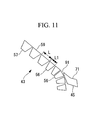
- Fig. 11 is a partial front view showing part of the moving sheet-guiding portion 43.
- the upstream part of the moving sheet-guiding portion 43 is provided with chambers 56 that are possibly positioned away from the sheet transport path S and the chambers 57 that do not have that possibility when the moving sheet-guiding portion 43 moves in the sheet transport direction SH according to the size of the sheet 9.
- the shapes of the chambers 57 and the chambers 56 are made to differ. Specifically, the length L1 of the chambers 56 along the sheet transport direction SH is made smaller than the length L of the chambers 57 along the sheet transport direction SH.
- a discontinuous portion 91 is formed at the joining portion of the stationary sheet-guiding portion 45 and the moving sheet-guiding portion 43. Because the length L1 of the chamber 56 along the sheet transport direction SH is made to be smaller than the length L of the chamber 57 along the sheet transport direction SH, the discontinuous portion 91 formed by the chambers 56 can be smaller than that formed by the chambers 57. Accordingly, because disturbances, due to the discontinuous portion 91, applied to the sheet 9 can be reduced, it is possible to further reduce instability of the sheet 9.
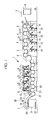
- Fig. 12 is a front view showing, in outline, the configuration of the delivery device 7 according to this embodiment.
- Fig. 13 is a front view showing, in outline, the configuration of another form of the delivery device 7 according to the fourth embodiment of the present invention.
- the stationary sheet-guiding portion 45 is extended to substantially the midpoint of the straight portion 51.
- the portions that the moving sheet-guiding portion 43 faces in the sheet transport path S are the horizontal portion 55, the convex curved portion 53, and a portion up to substantially the midpoint of the straight portion 51.
- the moving sheet-guiding portion 43 guides the sheet 9 between substantially the midpoint of the straight portion 51 and the downstream side thereof.
- the tracks 69 are provided so as to be away from the sheet moving path S from substantially the midpoint of the straight portion 51 toward the upstream side.
- the stationary sheet-guiding portion 45 is formed of a first stationary chamber 93 and a second stationary chamber 95.
- the first stationary chamber 93 guides the sheet 9 located at concave curved portion 49.
- the first stationary chamber 93 has a hollow box shape and is secured below the delivery shaft 37 around the circumference thereof.
- the second stationary chamber 95 guides the sheet 9 at an upstream portion of the straight portion 51.
- the second stationary chamber 95 has a hollow box shape and is secured along the sheet transport path S.
- the external portion of the downstream end of the second stationary chamber 95 is cut out in such a manner as to be strongly chamfered in front elevational view (in the direction orthogonal to the plane of the drawing of Fig. 12 .) (see Fig. 12 ). This is to enable the chambers 57 of the moving sheet-guiding portion 43 to easily move in the direction away from the sheet transport path S.
- the guide surfaces of the first stationary chamber 93 and the second stationary chamber 95 at the sheet transport path S side are formed so as to be substantially parallel to the sheet transport path S, and air discharge nozzles similar to those in the chamber 57 are disposed at intervals in a plurality of lines in the sheet transport direction SH.
- the straight portion 51 is an inclined plane surface, a centrifugal force is not exerted on the sheet 9 passing therealong, and the force becomes small because the weight of the sheet 9 is applied to the guide surface 59.
- the straight portion 51 is a portion where the disturbance acting on the sheet 9 that is being transported is minimum.
- the moving sheet-guiding portion 43 covers a region up to substantially the midpoint of the straight portion 51, the joining portion between the stationary sheet-guiding portion 45 and the moving sheet-guiding portion 43 can be positioned at a portion where the disturbance is minimum. By doing so, the influence of the disturbance occurring at the discontinuous portion 91 of the joining portion on the sheet 9 can be minimized. Therefore, the sheet 9 can be transported in a stable attitude.
- this joining portion is away from the convex curved portion 53, it is possible to prevent the sheet 9 from being affected by the disturbance caused by the centrifugal force that acts on the convex curved portion 53 being exerted on discontinuities at the joining portion.
- the structure of the chambers 57 is the same as that in the first embodiment, the chambers 58 of the second embodiment and/or the chambers 56 of the third embodiment may be used.
- the first stationary chamber 93 and the second stationary chamber 95 may be formed of multiple box-shaped structures divided in the sheet transport direction SH.
- a plate-shaped guide plate 97 may be used instead of the second stationary chamber 95, as shown in Fig. 13 .
- a fifth embodiment of the present invention will be described with reference to Fig. 14 .
- the basic configuration of this embodiment is the same as that of the fourth embodiment, that is, the first embodiment, except for the configuration of the sheet-guiding device 29. Therefore, in this embodiment, only the differences are described, and duplicated descriptions of the other parts will be omitted.
- the same components as those of the first embodiment are assigned the same reference numerals and detailed descriptions will be omitted.
- Fig. 14 is a front view showing, in outline, the configuration of the delivery device 7 according to this embodiment.
- a downstream end of the second stationary chamber 95 of the stationary sheet-guiding portion 45 is provided extending to a downstream end of the straight portion 51.
- portions where the moving sheet-guiding portion 43 faces the sheet transport path S are the horizontal portion 55 and the convex curved portion 53.
- the moving sheet-guiding portion 43 guides the sheet 9 from the convex curved portion 53 to the downstream side.
- the tracks 69 are disposed away from the sheet moving path S, toward the upstream side, at a boundary of the convex curved portion 53 and the straight portion 51.
- the moving sheet-guiding portion 43 covers a region up to the convex curved portion 53, the stationary sheet-guiding portion 45 and the moving sheet-guiding portion 43 are joined at a high position. Consequently, because a large space is formed below the joining portion of the stationary sheet-guiding portion 45 and the moving sheet-guiding portion 43, it is possible to dispose the chambers 57 outside the sheet transport path S at this portion with some allowance. In addition, because the number of chambers 57 becomes smaller, it is easy to install the supply pipe system 77.
- the structure of the chambers 57 is the same as that in the first embodiment, the chambers 58 of the second embodiment and/or the chambers 56 of the third embodiment may be used.
- the first stationary chamber 93 and the second stationary chamber 95 may be formed of multiple box-shaped structures divided in the sheet transport direction SH.
- the sheet-fed perfecting press is described merely as an example; however, the present invention may be applied to a sheet-fed press for single-sided printing or to a sheet-fed press for two-color printing or multi-color printing instead of four-color printing.
- the present invention is not limited to the embodiments described above; suitable modifications are possible without departing from the spirit of the invention.
- the moving sheet-guiding portion 43 may be driven independently of the vacuum suction carriage 31.
- the trajectory of the sheet transport path S may have various shapes.
Landscapes
- Engineering & Computer Science (AREA)
- Mechanical Engineering (AREA)
- Feeding Of Articles By Means Other Than Belts Or Rollers (AREA)
- Supply, Installation And Extraction Of Printed Sheets Or Plates (AREA)
- Discharge By Other Means (AREA)
Abstract
Provided is a sheet-fed press capable of reliably transport a printed sheet in a stable attitude without fluttering even when using a various sheet sizes. A sheet-fed perfecting press (1) including a sheet-guiding device (29) that has air discharge nozzles (65) on guide surfaces (59) and that guides a sheet (9) which is transported while being gripped by a gripper (35), and a vacuum suction carriage (31) that is provided downstream of the sheet-guiding device (29) in a sheet transport direction and that applies a brake to the sheet (9). The sheet-guiding device (29) is formed of a moving sheet-guiding portion (43), part of which forms a downstream portion in the sheet transport direction and which is movable in the sheet transport direction, and a stationary sheet-guiding portion (45) that forms an upstream portion in the sheet transport direction. The moving sheet-guiding portion (43) is formed of chambers (57) formed by dividing the moving sheet-guiding portion (43) into multiple parts in the sheet transport direction so that the chambers (57) each have the air discharge nozzles (65), adjacent ones being connected in a bendable manner.
Description
- The present invention relates to sheet-fed presses.
- In a delivery device of a sheet-fed press, because a printed sheet is transported while a leading end thereof is gripped by a gripper in a state where a printed surface is not sufficiently dried, the entire sheet tends to flutter as it is transported.
With this fluttering, the sheet contacts surrounding parts and is rubbed, possibly causing damage to or staining on the sheet, or on the printed surface thereof.
Various types of devices that prevent this problem and that transport the sheet in a stable attitude have been proposed (for example, Patent Documents 1 and 2). - In the one disclosed in Patent Document 1, a guide is provided below a sheet transport path along the entire surface thereof, and a sheet is guided by air present between a guide surface and the sheet while preventing the downward movement of the sheet. A moving guide that moves in the sheet transport direction according to a positional change of a vacuum suction carriage is attached at a downstream end of the guide in such a manner as to be capable of coming in and out.
Because this does not prevent the upward movement of the sheet, for example, at a portion where the sheet transport path is convex upward, the sheet moves upward due to a centrifugal force that acts upward, thus possibly causing a fluctuation such as fluttering. Because the fluttering occurs in the sheet in this way, the sheet abuts against the guide surface, thus possibly causing damage or staining. - In the one disclosed in Patent Document 2, air is actively ejected along the guide surface, and a sheet is attracted to the guide surface by means of the Bernoulli effect resulting therefrom, i.e., the upward movement of the sheet is prevented. Downward movement of the sheet approaching the guide surface is prevented due to an ejected air layer, i.e., the sheet is prevented from coming into contact with the guide surface. In this way, the sheet is transported in a stable attitude.
Because the guide for ejecting air disclosed in Patent Document 2 is stationary, when printing on sheets with different sizes, for example, a plate-shaped guide like that shown in Patent Document 1, which is capable of coming in and out, is provided between a vacuum suction carriage moving in the sheet transport direction and the stationary guide. -
- Patent Document 1: Japanese Unexamined Patent Application, Publication No.
2004-161003 - Patent Document 2: Japanese Unexamined Patent Application, Publication No.
HEI 11-138752 - However, with a sheet-fed press that processes various sheet sizes using devices disclosed in Patent Document 2, the behavior of the sheet varies because the influence on the sheet differs between the plate-shaped guide and the guide on whose surface air is ejected. Because the sheet flutters due to a change in this behavior, the sheet abuts against, for example, the plate-shaped guide, thus possibly causing damage or staining.
This causes a big problem when guiding a sheet having a printed surface on a back side that is not sufficiently dried, as in double-sided printing. - The present invention has been conceived in light of the circumstances described above, and an object thereof is to provide a sheet-fed press that is capable of reliably transporting printed sheets in a stable attitude without making the sheet flutter even when using various sheet sizes.
- In order to solve the above problems, the present invention employs the following solutions.
Specifically, a first aspect of the present invention is to provide a sheet-fed press comprising a sheet guide that has air discharge portions on guide surfaces and that guides a printed sheet which is transported while being gripped by a gripper; and a vacuum suction carriage that is provided downstream of the sheet guide in a sheet transport direction and that applies a brake to the sheet, wherein the sheet guide is formed of a moving sheet guide, part of which forms a downstream portion in the sheet transport direction and which is movable in the sheet transport direction, and a stationary sheet guide that forms an upstream portion in the sheet transport direction, the moving sheet guide is formed of divided sheet guides formed by dividing the moving sheet guide into multiple parts in the sheet transport direction so that the divided sheet guides each have the discharge portions, adjacent ones being connected in a bendable manner. - According to this aspect, because the moving sheet guide is formed of the divided sheet guides formed by dividing the moving sheet guide into multiple parts in the sheet transport direction, adjacent ones being connected in a bendable manner, it is possible to suitably form a curved or a bent shape.
Accordingly, because it is possible for the moving sheet guide to make a portion of its stationary sheet guide side to locate outside the sheet transport path, when the length of the moving sheet guide in the sheet transport direction is sufficient, in other words, when it is too long, that portion can be located at a position outside the sheet transport path.
In addition, even when the sheet transport path has a curved portion, this curved portion can be formed at an appropriate position of the moving sheet guide in the sheet transport direction.
By doing so, even when the moving sheet guide moves in the sheet transport direction, a continuous sheet guide can be formed along the sheet transport path by the stationary sheet guide and the moving sheet guide. - In addition, when the moving sheet guide is moved in the sheet transport direction by substantially the same amount as the amount of movement of the vacuum suction carriage, which moves according to a change in sheet size, the sheet guide can be made to continuously exist up to the vicinity of the vacuum suction carriage even when processing any length of sheet.
Because the divided sheet guides each have the air discharge portions on the guide surfaces, the sheet guide can actively eject the air over the entire length thereof along the guide surfaces. In addition, because the transported sheet is attracted to the guide surfaces by the Bernoulli effect due to an airflow flowing along the guide surfaces, an upward movement is prevented. In addition, because the downward movement of the sheet approaching the guide surfaces is reduced by the ejected air layer, the sheet can be prevented from contacting the guide surfaces.
In this way, because it is possible to transport the transported sheet in a stable attitude, the sheet can be reliably prevented from being damaged or stained by abutting against, for example, the sheet guide. - In addition, the moving sheet guide preferably has a length covering a certain region in the sheet transport direction of the sheet guide. This is because parts are congested around the vacuum suction carriage, and therefore, it is difficult to move the divided sheet guides outside the sheet transport path.
Furthermore, when making the length of the moving sheet guide in the sheet transport direction large in this way, the attitude of the sheet transported to the vacuum suction carriage can be adjusted in a stable attitude at a portion of the moving sheet guide. Accordingly, for example, when some degree of fluttering of the sheet is allowed with the sheet-fed press performing single-sided printing, it is possible to use a guide without providing air discharge portions on the guide surfaces at the downstream portion of the stationary guide, that is, to use a thin plate-shaped guide.
In this way, when using the plate-shaped guide at the downstream side of the stationary guide, it is possible to simplify the structure of the divided sheet guides and their moving portion because the amount of movement in the thickness direction becomes small when moving the upstream side of the moving sheet guide outside the sheet transport path. - In the aspect described above, it is preferable that the moving sheet guide be integrally engaged to the vacuum suction carriage.
By doing so, it is possible to automatically move the moving sheet guide to a predetermined position according to the movement of the vacuum suction carriage.
Accordingly, driving means for moving the moving sheet guide can be eliminated, thus simplifying the structure and reducing the manufacturing cost. - In the aspect described above, the sheet guide may have a first structure in which it has a horizontal portion that is substantially horizontal and that follows after the vacuum suction carriage, a straight portion that is disposed upstream in the sheet transport direction and that extends vertically, and a curved portion that connects the horizontal portion and the straight portion, and the moving sheet guide covers a region up to at least the vicinity of an upstream end of the straight portion.
- When the sheet passes the curved portion, a centrifugal force acts thereon. In addition, at a joining portion of the stationary sheet guide and the moving sheet guide, because the upstream side of the moving sheet guide is located outside the sheet transport path, a certain discontinuous portion is inevitably formed. This causes a disturbance that makes the transported sheet flutter.
According to the present invention, because the moving sheet guide covers the region up to at least the vicinity of the upstream end of the straight portion, the joining portion of the stationary sheet guide and the moving sheet guide is located significantly away from the curved portion.
Accordingly, because the sheet is unaffected by a disturbance caused by the centrifugal force that acts on the curved portion being exerted on discontinuities at the joining portion of the stationary sheet guide and the moving sheet guide, fluttering of the sheet can be easily prevented. - In the aspect described above, the sheet guide may have a second structure in which it has a horizontal portion that is substantially horizontal and that follows after the vacuum suction carriage, a straight portion that is disposed upstream in the sheet transport direction, and a curved portion that connects the horizontal portion and the straight portion, and the moving sheet guide covers a region up to the curved portion.
- In this way, because the moving sheet guide covers the region up to the curved portion, for example, when the horizontal portion is located above, a space below the joining portion of the stationary sheet guide and the moving sheet guide can be made large; therefore, the divided sheet guides at this portion and their moving portion can be disposed with some margin.
- In the aspect described above, the sheet guide may have a third structure in which it has a horizontal portion that is substantially horizontal and that follows after the vacuum suction carriage, a straight portion that is disposed upstream in the sheet transport direction, and a curved portion that connects the horizontal portion and the straight portion, and the moving sheet guide covers a region up to substantially the midpoint of the straight portion.
- In this way, because the moving sheet guide covers the region up to substantially the midpoint of the straight portion, the joining portion of the stationary sheet guide and the moving sheet guide can be located at a portion where the disturbance is minimized.
In addition, because the moving sheet guide is away from the curved portion, it is possible to prevent the sheet from being affected by the disturbance caused by the centrifugal force that acts on the curved portion being exerted on discontinuities at the joining portion of the stationary sheet guide and the moving sheet guide. - In addition, with the first and the third structures described above, the curved portion is formed to have a predetermined radius of curvature, and the guide surfaces of the divided sheet guides located at the curved portion are curved along the sheet transport direction so as to have the predetermined radius of curvature.
- In this way, because the curved portion is formed so as to have a predetermined radius of curvature, the centrifugal force acting on the sheet is constant.
In addition, because the guide surfaces of the divided sheet guides located at the curved portion are curved so as to have a predetermined radius of curvature along the sheet transport direction, the surface of the moving sheet guide located at the curved portion is formed in a smooth continuous shape. When the surface of the curved portion is formed in a smooth continuous shape, because points at which the Bernoulli effect due to the air ejected from the discharge portions occurs form a smooth continuous shape, an attraction force acting on the sheet becomes constant.
Accordingly, because the sheet is reliably attracted in a stable manner, it is possible to effectively prevent the sheet on which the centrifugal force acts from being lifted. - In addition, "the divided sheet guides located at the curved portion" indicates all divided sheet guides that are possibly located at the curved portion within a region where the moving sheet guide moves in the sheet transport direction. Accordingly, the divided sheet guides having curved guide surfaces may be located at the horizontal portion or the straight portion. In that case, because a distance between the guide surfaces and the sheet varies depending on their positions, it is preferable to adjust the length of the divided sheet guides in the sheet transport direction so that this variance should be within a range that does not affect the behavior of the sheet.
- In the aspect described above, upstream in the sheet transport direction, the length of the divided sheet guides, along the sheet transport direction, located at a portion away from a transport path of the sheet may be smaller than the length of the divided sheet guides, along the sheet transport direction, located downstream.
- In this way, upstream in the sheet transport direction, the length of the divided sheet guides, along the sheet transport direction, located at a portion away from the sheet transport path, i.e., located at a portion joining with the stationary sheet guide, is smaller than the length of the divided sheet guides, along the sheet transport direction, located downstream; therefore, it is possible to make the size of the discontinuous portion formed at the joining portion of the stationary sheet guide and the moving sheet guide small.
Accordingly, because it is possible to make the size of the discontinuous portion formed at the joining portion of the stationary sheet guide and the moving sheet guide small, the disturbance acting on the sheet can be minimized. - In the aspect described above, a guide-surface component that extends substantially along the guide surface and that allows expansion and contraction may be attached between the adjacent divided sheet guides.
- In this way, because the guide-surface component that extends substantially along the guide surfaces is attached between the adjacent divided sheet guides, it is possible to prevent the Bernoulli effect from being reduced due to air leaking from the gap between the adjacent divided sheet guides.
In addition, because the guide-surface component allows expansion and contraction, even when the divided sheet guides are, for example, positioned at the curved portion to be bent, thus enlarging the gap between the adjacent divided sheet guides, they can conform to this bending. - According to the present invention, because the moving sheet guide is formed of the divided sheet guides formed by dividing the moving sheet guide into multiple parts in the sheet transport direction, adjacent ones being connected in a bendable manner, even when the moving sheet guide moves in the sheet transport direction, it is possible to make the sheet guide continuous along the sheet transport path by using the stationary sheet guide and the moving sheet guide.
In addition, by moving the moving sheet guide in the sheet transport direction by substantially the same amount as the amount of movement of the vacuum suction carriage that moves according to a change in sheet size, the sheet guide can be continuously provided in a region up to the vicinity of the vacuum suction carriage even when processing any length of sheet.
Because the divided sheet guides each have air discharge portions on the guide surfaces, it is possible to transport the transported sheet in a stable attitude and to reliably prevent the sheet from being damaged or stained by abutting against, for example, the sheet guide. -
- [
FIG. 1] Fig. 1 is a front view showing the overall schematic configuration of a sheet-fed perfecting press according to a first embodiment of the present invention. - [
FIG. 2] Fig. 2 is a front view showing, in outline, the configuration of a delivery device according to the first embodiment of the present invention. - [
FIG. 3] Fig. 3 is a perspective view showing chambers according to the first embodiment of the present invention. - [
FIG. 4] Fig. 4 is a sectional view taken along X-X ofFig. 3 . - [
FIG. 5] Fig. 5 is a schematic view showing an arrangement, at a straight portion, of the chambers according to the first embodiment of the present invention. - [
FIG. 6] Fig. 6 is a schematic view showing an arrangement, at a convex curved portion, of the chambers according to the first embodiment of the present invention. - [
FIG. 7] Fig. 7 is a front view showing, in outline, the configuration of a delivery device according to the first embodiment of the present invention. - [
FIG. 8] Fig. 8 is a front view showing, in outline, the configuration of another form of a delivery device according to the first embodiment of the present invention. - [
FIG. 9] Fig. 9 is a partial front view showing part of a moving sheet-guiding portion according to a second embodiment of the present invention. - [
FIG. 10] Fig. 10 is a front view of a chamber according to the second embodiment of the present invention. - [
FIG. 11] Fig. 11 is a partial front view showing part of a moving sheet-guiding portion according to a third embodiment of the present invention. - [
FIG. 12] Fig. 12 is a front view showing, in outline, the configuration of a delivery device according to a fourth embodiment of the present invention. - [
FIG. 13] Fig. 13 is a front view showing, in outline, the configuration of another form of a delivery device according to the fourth embodiment of the present invention. - [
FIG. 14] Fig. 14 is a front view showing, in outline, the configuration of a delivery device according to a fifth embodiment of the present invention. Explanation of Reference Signs: -
- 1:
- sheet-fed perfecting press
- 9:
- sheet
- 29:
- sheet-guiding device
- 31:
- vacuum suction carriage
- 35:
- grippers
- 43:
- moving sheet-guiding portion
- 45:
- stationary sheet-guiding portion
- 51:
- straight portion
- 53:
- convex curved portion
- 55:
- horizontal portion
- 56:
- chambers
- 57:
- chambers
- 58:
- chambers
- 59:
- guide surface
- 63:
- sheet member
- 65:
- air discharge nozzle
- 71:
- guide surface
- R:
- radius of curvature
- S:
- sheet transport path
- SH:
- sheet transport direction
- Embodiments of the present invention will be described below with reference to the drawings.
- A first embodiment of the present invention is described below with reference to
Figs. 1 to 7 .
Fig. 1 is a front view showing the overall schematic configuration of a sheet-fed perfecting press (sheet-fed press) 1.
The sheet-fed perfecting press 1 has a paper feeder 3 that supplies stacked sheets, which are materials to be printed on, from the upstream side where the sheets are supplied to the downstream side, a plurality ofprinting units 5 that print, for example, different colors to realize color printing, and adelivery device 7 that places the printed sheets in a stack. - The paper feeder 3 supplies the
sheets 9 stacked on apaper feeding tray 11 by consecutively picking them up one by one from the top with a paper feeding mechanism (paper feed, cam, etc.), not shown.
Thepaper feeding tray 11 is configured so as to move upward in response to the supply of thesheets 9 so that the paper feeding mechanism maintains a substantially constant positional relationship with respect to thesheets 9. - A plurality of
printing units 5 are provided, one for each color. In this embodiment, a four-color press for printing with four colors, including C (cyan), M (magenta), Y (yellow) and BL (black), is shown; a total eightprinting units 5 are provided because the printing is performed on both sides of the material to be printed on.
Printing is performed on the back surface of the sheet 9 (lower surface) using the first fourprinting units 5 and is performed on the front surface of the sheet 9 (upper surface) using the latter fourprinting units 5. A connectingunit 6 that adjusts printed surfaces of thesheet 9 is provided between the groups ofprinting units 5. - Each
printing unit 5 has aninking unit 13 that supplies ink, a dampeningdevice 15 that supplies a dampening solution, a plate cylinder 17 that is provided facing the inkingunit 13 and the dampeningdevice 15, ablanket cylinder 19 that faces the plate cylinder 17, animpression cylinder 21 that faces theblanket cylinder 19, and atransfer cylinder 23 that is provided between theimpression cylinder 21 in eachprinting unit 5. - The inking
unit 13 has a plurality of ink rollers which supply ink in turn to the plate cylinder 17 from ink reservoirs in which the ink is retained.
The dampeningdevice 15 has a plurality of rollers and supplies the dampening solution that is retained in a water pan to the plate cylinder 17.
The inkingunit 13 and the dampeningdevice 15 are separated from the plate cylinder 17 during a non-printing period, i.e., while printing is not performed. - The plate cylinder 17 has a cylindrical shape, around which a plate on which a printing image is formed is wound on an outer circumference thereof. A plate is created and changed for each image to be printed.
Here, although not shown in the drawing, part of the outer circumference of the plate cylinder 17 is cut out within an angular range in the axial direction. At this position, plate tightening devices that hold a plate head corresponding to an upstream end of the plate and a plate end corresponding to the downstream end of the plate to secure them are provided. - A
blanket cylinder 19 receives ink on the plate on the plate cylinder 17 and transfers the ink to thesheet 9 passing between theimpression cylinder 21 and the blanket cylinder 19 (offset printing). A blanket formed of an elastic material, for example rubber, is wound around an outer circumference of theblanket cylinder 19.
Although not shown in the drawing, part of the outer circumference of theblanket cylinder 19 is cut out within an angular range in the axial direction, where a pair of shafts that hold an upstream end and a downstream end of the blanket to secure them is provided.
In addition, theblanket cylinder 19 is configured such that it can be separated from theimpression cylinder 21 and the plate cylinder 17 during a non-printing period, i.e., while printing is not performed. - The
impression cylinder 21, which has a cylindrical shape, is disposed facing theblanket cylinder 19. In addition, theimpression cylinder 21 in this embodiment is arranged such that its diameter is twice as large as the diameter of the plate cylinder 17 or theblanket cylinder 19, which is a so-called double-diameter cylinder structure; however, it is not limited thereto. The present invention can be suitably implemented even when using an impression cylinder of a single-diameter type having the same diameter as the plate cylinder 17.
In this embodiment, gripping device (not shown) that hold the leading end of thesheet 9 are provided at two positions that face each other across the axial center, around the circumferential surface of theimpression cylinder 21.
In addition, theimpression cylinder 21 contacts theblanket cylinder 19 via thesheet 9 during printing, thus applying a desired force to thesheet 9 supplied between theblanket cylinder 19 and theimpression cylinder 21. By doing so, the ink on theblanket cylinder 19 is transferred onto thesheet 9. - The
transfer cylinder 23, which has a cylindrical shape, is disposed between theimpression cylinders 21 provided in each of theprinting units 5. In addition, thetransfer cylinder 23 in this embodiment is arranged such that its diameter is twice as large as the diameter of the plate cylinder 17 or theblanket cylinder 19, which is a so-called double-diameter cylinder structure; however, it is not limited thereto. Similar to the above-described impression cylinder, the present invention can be suitably implemented even when using a transfer cylinder of a single-diameter type having the same diameter as the plate cylinder 17.
In this embodiment, gripping device (not shown) that hold the leading end of thesheet 9 are provided at two positions that face each other across the axial center, around the circumferential surface of thetransfer cylinder 23. Thetransfer cylinder 23 transports thesheet 9 from theimpression cylinder 21 located upstream toward theimpression cylinder 21 located downstream. - The above-described
inking units 13, dampeningdevices 15, plate cylinders 17,blanket cylinders 19,impression cylinders 21, and transfercylinders 23 are rotated by a single main motor (not shown) provided in the sheet-fed perfecting press 1 in such a manner that circumferential speeds thereof are substantially the same.
In other words, a rotational force from the main motor is transmitted to each of the members via gears. - Next, the
delivery device 7 will be described with reference toFigs. 2 to 7 .Figs. 2 and7 are front views showing, in outline, the configuration of thedelivery device 7.Figs. 3 to 6 are, respectively, a perspective view, a sectional view, and schematic views of a divided sheet guide according to the present invention.
As shown inFig. 1 and2 , thedelivery device 7 has achain gripper 25 that grips the leading end of thesheet 9 and transports it, adelivery tray 27 on which thesheets 9 are stacked, a sheet-guiding device (sheet guide) 29 that guides the transportedsheet 9, and avacuum suction carriage 31 that applies a brake to thesheet 9 travelling upstream of thedelivery tray 27. - The
chain gripper 25 hasendless chains 33 andgrippers 35.
A pair ofendless chains 33 is disposed at both sides of thedelivery device 7 and bridged between adelivery shaft 37 adjacent to theimpression cylinder 21 and a drivenshaft 39 disposed at an upper position at a downstream end of thedelivery tray 27.
Theendless chains 33 are guided by a guiding member (not shown) and driven along a circling path by passing below thedelivery shaft 37, moving obliquely upward, substantially horizontally moving above thedelivery tray 27, winding from a lower part of the drivenshaft 39 toward an upper part thereof, substantially horizontally moving above thedelivery tray 27, moving obliquely downward, and returning to an upper portion of thedelivery shaft 37. - The
grippers 35 are disposed so as to extend in the width direction B (seeFig. 3 ; in the direction orthogonal to the planes of the drawings inFig. 2 , andFigs. 4 to 7 ), and both ends thereof are held by both of theendless chains 33, respectively.
A plurality of gripping device 41 (seeFig. 5 ) for gripping or releasing thesheet 9 by an opening/closing operation are attached to thegrippers 35 with gaps therebetween in the width direction B. - The
grippers 35 grip the leading end of thesheet 9 at a position where thedelivery shaft 37 joins theimpression cylinder 21, hold thesheet 9 until releasing it above thedelivery tray 27, and transport it in the sheet transport direction SH.
In this embodiment, because a position where thegripping device 41 grip thesheet 9 is substantially the same as the position of the moving trajectory of theendless chains 33, both of the moving trajectories are substantially the same. Specifically, of the moving trajectories of theendless chains 33, the section of the moving trajectory of theendless chains 33 from a position where thedelivery shaft 37 receives thesheet 9 to a position where it passes over thevacuum suction carriage 31 corresponds to a sheet transport path S of the present invention. - The sheet-guiding
device 29 guides thesheet 9 that is gripped and transported by thegrippers 35 to thevacuum suction carriage 31. The sheet-guidingdevice 29 has a concavecurved portion 49 for guiding thesheet 9 that passes below thedelivery shaft 37; astraight portion 51 for guiding thesheet 9 that linearly moves obliquely upward from an exit of thedelivery shaft 37; a convex curved portion (curved portion) 53 that convexly curves upward for guiding thesheet 9 that changes its travelling direction in the horizontal direction, following after the downstream end of thestraight portion 51; and, following after this, ahorizontal portion 55 for guiding thesheet 9 that substantially horizontally moves. - The sheet-guiding
device 29 is provided with a moving sheet-guiding portion (moving sheet guide) 43, a stationary sheet-guiding portion (stationary sheet guide) 45, and a compressedair supplying portion 47.
The moving sheet-guidingportion 43 guides thesheet 9 at thestraight portion 51, the convexcurved portion 53, and thehorizontal portion 55.
The moving sheet-guidingportion 43 is formed of a plurality of chambers (divided sheet guides) 57 that are continuously provided, with each adjacent one being connected together.
Fig. 3 is a perspective view showing thechambers 57.Fig. 4 is a sectional view taken along X-X ofFig. 3 .Fig. 5 is a schematic view showing the arrangement of thechambers 57 at thestraight portion 51.Fig. 6 is a schematic view showing the arrangement of thechambers 57 at the convexcurved portion 53. - The
chambers 57 are hollow isosceles trapezoidal prisms and are disposed such that the longitudinal direction thereof extends in the width direction B. Each of thechambers 57 is provided in such a manner that guide surfaces 59 constituting the longer base of the trapezoid cross section faces the sheet transport path S.
In this way, because thechambers 57 are formed of planar surfaces, it is easy to manufacture them at low cost compared to those having curved surfaces. - The length of the
chambers 57 in the width direction B is formed larger than the width of thelargest sheet 9 to be printed.
As shown inFig. 4 , theadjacent chambers 57 are connected so as to be rotatable relative to each other by ahinge 61 whose axial center extends in the width direction B near theguide surface 59. In other words, theadjacent chambers 57 are connected to each other so as to be capable of being bent, in the sheet transport direction SH, with the vicinity of theguide surface 59 serving as a boundary. - Because the guide surfaces 59 are planar, the plurality of guide surfaces 59 of the
chambers 57 located at thehorizontal portion 55 andstraight portion 51 form a planar surface (flat surface) substantially parallel to the sheet transport path S, as shown inFig. 5 .
On the other hand, as shown inFig. 6 , the plurality of guide surfaces 59 of thechambers 57 located at the convexcurved portion 53 form a polygonal shape whose front and rear ends in the sheet transport direction SH contact a virtual guide surface K where the guide surfaces 59 are supposed to be substantially parallel to the sheet transport path S. - Because the sheet transport path S corresponding to the convex
curved portion 53 curves with a constant curvature, a virtual guide surface K that is substantially parallel thereto is part of a cylindrical surface having a constant radius of curvature R.
When the maximum distance H1 (seeFig. 6 ) between the virtual guide surface K and theguide surface 59 becomes large, theguide surface 59 is away from thesheet 9 transported at that portion; therefore, the Bernoulli effect cannot occur.
Because the maximum distance H1 can be calculated by using the length L and the radius of curvature R of thechamber 57 in the sheet transport direction SH, the length L is set so that the maximum distance H1 is large enough that the Bernoulli effect can occur. - In addition, a thin rubber sheet member (guide-surface component) 63 is attached between the
adjacent chambers 57 in such a manner as to connect both the guide surfaces 59.
Thesheet member 63 may be formed of a thin cloth, or it may be attached in such a manner as to connect opposing surfaces of thechambers 57.
As shown inFig. 3 , thechambers 57 according to this embodiment have a configuration in which a plurality of air discharge nozzles (discharge portions) 65 capable of discharging compressed air toward both lateral ends of thechambers 57 are provided in parallel on the surfaces thereof at predetermined intervals, with the center portion along the sheet transport direction SH serving as a boundary. Specifically, theair discharge nozzles 65 are disposed in pairs in two columns so as to be symmetrical with respect to the center line of the chambers 57 (in the direction along the sheet transport direction SH) such that openings thereof are oriented in the direction in which the compressed air is outwardly ejected. However, they are not limited thereto. Theair discharge nozzles 65 may be provided such that the compressed air is ejected in the transport direction, or the number of columns may be increased. - Protruding cylindrical supporting
portions 67 are provided at both sides of thechambers 57 in the width direction B.
The supportingportions 67 are fitted intracks 69 disposed at both side surfaces of thechambers 57 in the width direction B and are held so as to be movable along thetracks 69.
Thetracks 69 are provided substantially parallel to the sheet transport path S at thestraight portion 51, the convexcurved portion 53, and thehorizontal portion 55, and are provided away from the sheet moving path S at the upstream side of thestraight portion 51. Thetracks 69 of a portion at the upstream side of thestraight portion 51, where thetracks 69 start going away from the sheet transport path S, have a curvature so that theadjacent chambers 57 do not abut each other. - In addition, the
tracks 69 at thehorizontal portion 55 are provided up to a position in the vicinity of thevacuum suction carriage 31 that handles the minimum length (the length in the sheet transport direction SH) of thesheet 9 to be printed.
Thechamber 57 at the most downstream side in the sheet transport direction SH is connected to the supporting portion of thevacuum suction carriage 31 by the connectingmember 70. - The stationary sheet-guiding
portion 45 guides thesheet 9 at the concavecurved portion 49.
The stationary sheet-guidingportion 45 has a hollow box shape and is secured below thedelivery shaft 37 along the outer circumference thereof. The stationary sheet-guidingportion 45 at thedelivery shaft 37 side is constructed of aguide surface 71 that is formed to be substantially parallel to the sheet transport path S. The length of theguide surface 71 in the width direction B is larger than the width of thelargest sheet 9 to be printed.
Although not shown in the drawing, similar to thechambers 57, a plurality of air discharge nozzles are arranged at intervals on theguide surface 71, the air discharge nozzles being capable of discharging compressed air toward both width ends of the sheet, with the center portion along the sheet transport direction SH serving as a boundary. In this embodiment, as an example of the arrangement of the air discharge nozzles, they are provided in a plurality of columns at intervals in the sheet transport direction SH so as to be paired; however, other known arrangements or constructions may, of course, be employed. - As shown in
Fig. 2 , thedownstream end surface 72 of the stationary sheet-guidingportion 45 in the sheet transport direction SH is constructed such that an angle formed between it and theguide surface 71 is acute. This is to allow thechambers 57 at the moving sheet-guidingportion 43 easily move in the direction away from the sheet transport path S.
In this embodiment, the stationary sheet-guidingportion 45 is formed of a single box-shaped structure; however, it may be formed of multiple box-shaped structures divided in the sheet transport direction SH. - The compressed
air supplying portion 47 has ablower 73, abuffer tank 75, and asupply pipe system 77.
Theblower 73 is a supply source of the compressed air, and a plurality ofblowers 73 may be used when necessary. Alternatively, another means may be used as the supply source of the compressed air, for example, a compressor.
Thebuffer tank 75 is a tank for temporarily retaining the compressed air sent from theblower 73 to reduce variations in pressure and the supply amount of the compressed air. In addition, when there is limited space for the layout inside the device, instead of providing thebuffer tank 75, a structure in which a pipe is directly branched off from theblower 73 to adjust the pressure using a regulating valve may be used. - The
supply pipe system 77 has collectingpipes 79,rigid supply pipes flexible supply pipes valves 89.
The plurality of collectingpipes 79 are provided to serve as intermediate tanks for supplying the compressed air to the plurality ofchambers 57, respectively.
The collectingpipes 79 are connected to thebuffer tank 75 by the respectiverigid supply pipes 81. Therigid supply pipes 81 are provided with the regulatingvalves 89 that adjust the supply amount of the compressed air. - The collecting
pipes 79 are connected to a plurality of theflexible supply pipes 83 that respectively supply the compressed air todifferent chambers 57.
Theflexible supply pipes 83 are formed, for example, in a loop shape at an intermediate portion thereof so that the length to be connected can be automatically varied when the positions of thechambers 57 vary.
Thechambers 57 to which the compressed air is supplied via the collectingpipes 79 are always located at thestraight portion 51, the convexcurved portion 53, and thehorizontal portion 55 even when the length of thesheet 9 varies. - The
chambers 57 that form the upstream side of the sheet-guidingdevice 43 in the sheet transport direction SH and that may possibly be outside the sheet transport path S when the length of thesheet 9 varies are connected to thebuffer tank 75 by theflexible supply pipes 85 that have a loop shape at an intermediate portion thereof and their length to be connected can be automatically varied according to positional changes of thechambers 57.
Theflexible supply pipes 85 are provided with the regulatingvalves 89 that adjust the supply amount of the compressed air.
Therigid supply pipe 87 is connected to the stationary sheet-guidingportion 45 and thebuffer tank 75 via the regulatingvalve 89. - The sheet-fed perfecting press 1 described above operates as follows.
Thesheets 9 stacked on thepaper feeding tray 11 in the paper feeder 3 are picked up from the top one by one by the paper feeding mechanism (not shown) and are supplied to theprinting unit 5.
The suppliedsheet 9 is gripped by the gripping device on thetransfer cylinder 23 in theprinting unit 5 and is then passed over from thetransfer cylinder 23 to theimpression cylinder 21. By repeating this operation, it is transported via the connectingunit 6 and eightprinting units 5. - In each
printing unit 5, water is supplied from a dampeningdevice 15 to non-image areas of the plate that is attached around the circumferential surface of the plate cylinder 17, and then ink is supplied to image areas of the plate from the inkingunit 13.
The print images on the plate obtained in this way are transferred onto theblanket cylinder 19.
The print images transferred onto theblanket cylinder 19 are transferred onto thesheet 9 that is transported by theimpression cylinder 21, thus carrying out single-color printing.
When passing through between theblanket cylinders 19 and the impression cylinders 17 in the first fourprinting units 5, four-color printing is carried out on the back surface of thesheet 9. Thereafter, when passing through the fourprinting units 5 located downstream, four-color printing is carried out on the front surface of thesheet 9 whose back surface is printed. Thesheet 9 that is printed on both sides thereof in this way is transported to thedelivery device 7. - The printed
sheet 9 is passed over from theimpression cylinder 21 at thefinal printing unit 5 to thegripper 35 that winds around thedelivery shaft 37.
Thegripper 35 grips the leading end portion of thesheet 9, moves it along the sheet transport path S, releases it by means of a paper-release cam (not shown) when it arrives above thedelivery tray 27, and then releases thesheet 9.
Thesheet 9 released from thegripper 35 falls down while being slowed down (braked) in the traveling direction by thevacuum suction carriage 31. Thesheet 9 abuts against apaper stopper 32 to be aligned with the leading end portion thereof, and is then stacked on thesheets 9 that are already stacked on thedelivery tray 27. - At this time, by opening a
predetermined regulating valve 89, regulated compressed air is supplied to inner spaces of thechambers 57 located at thestraight portion 51, the convexcurved portion 53, and thehorizontal portion 55, and an inner space of the stationary sheet-guidingportion 45. The compressed air is not supplied to thechambers 57 whose guide surfaces 59 are not located in the sheet transport path S due to closing of the corresponding regulatingvalves 89.
As shown inFig. 3 , in this embodiment, the compressed air supplied to the inner spaces is ejected outward from theair discharge nozzle 65 in the width direction B along the guide surfaces 59 and 71. - When the transported
sheet 9 passes via the guide surfaces 59 and 71, a flow velocity difference (pressure difference) of the air occurs between the front and back surfaces of thesheet 9 due to an airflow flowing along the guide surfaces 59 and 71.
Because of this, a static pressure on the guide surfaces 59 and 71 is reduced, an attraction force (Bernoulli effect) that causes thesheet 9 to hug the guide surfaces 59 and 71 occurs, and therefore, thesheet 9 is attracted to the guide surfaces 59 and 71. - Because movement of the
sheet 9 attracted to the guide surfaces 59 and 71 toward the guide surfaces 59 and 71 is restricted by an air layer due to a continuously ejected air flow, thesheet 9 adopts a stable attitude at a position where the attraction force due to the Bernoulli effect balances the suppression force due to the air layer.
Because this state is continued from thedelivery shaft 37 up to the vicinity of thevacuum suction carriage 31, thesheet 9 can be transported in a stable attitude. By doing so, it is possible to reliably prevent thesheet 9 from being damaged or stained by abutting against the sheet guides or the like. - At this time, because the
sheet members 63 constitute part of the guide surfaces 59, it is possible to improve the continuity of the Bernoulli effect.
In addition, because thesheet members 63 can prevent air leakage from the gaps between thechambers 57, it is possible to prevent the Bernoulli effect from being partly reduced.
Attachment of thesheet members 63 can be omitted if the drop in the Bernoulli effect is not large according to the conditions, such as the size or the shape of thechambers 57, or the size of the gaps. - Next, a description will be given in a case in which printing is performed on
sheets 9 of different sizes, for example, a case where, as shown inFig. 2 , after completion of a printing operation in which printing is performed on asheet 9 of maximum size, as shown inFig. 7 , printing is performed on asmall size sheet 9.
Thevacuum suction carriage 31 is moved toward the drivenshaft 39 according to the length (sheet length) of thesmall size sheet 9 in the sheet transport direction SH to set it at a predetermined position corresponding to the sheet length. - In response to the movement of the
vacuum suction carriage 31, the mostdownstream chamber 57 connected to the connectingmember 70 moves to the drivenshaft 39 along thetracks 69.
When the mostdownstream chamber 57 moves, eachchamber 57 connected thereto moves along thetracks 69.
At this time, because the downstream portion of thechambers 57 that formed the convexcurved portion 53 moves to form thehorizontal portion 55, the length of thehorizontal portion 55 at the moving sheet-guidingportion 43 is automatically adjusted. Specifically, the distance between the moving sheet-guidingportion 43 and thevacuum suction carriage 31 is always maintained constant. - In addition, although the
downstream chambers 57 that formed thestraight portion 51 move to the convexcurved portion 53, because the length of thechamber 57 in the sheet transport direction SH is small, and because thechambers 57 are connected so as to have a bend therebetween, they can be bent in such a manner as to form the convexcurved portion 53.
Furthermore, thechambers 57 located outside the sheet transport path S move in turn along thetracks 69 by being bent at connecting portions to form thestraight portion 51.
Accordingly, when providing thechambers 57 having a length corresponding to the minimum sheet size to be used, the moving sheet-guidingportion 43 can reliably cover the region from downstream of the stationary sheet-guidingportion 45 to the vicinity of thevacuum suction carriage 31 even when printing asheet 9 of any size. - In addition, because the
sheet members 63 can expand and contract, even when thechambers 57 are, for example, positioned at the convexcurved portion 53 to be bent, resulting in the gap between theadjacent chambers 57 becoming large, they can conform to this bending.
In this way, because the moving sheet-guidingportion 43 is moved to a predetermined position in the sheet transport direction SH due to the movement of thevacuum suction carriage 31, driving means for moving the moving sheet-guidingportion 43 needs not be separately provided; therefore, the structure can be simplified accordingly, thus reducing the cost. - In this embodiment, because the moving sheet-guiding
portion 43 covers the region up to the vicinity of the upstream side of thestraight portion 51, a portion thereof joining with the stationary sheet-guidingportion 45 is located significantly away from the convexcurved portion 53.
Accordingly, because thesheet 9 is unaffected by a disturbance caused by a centrifugal force that acts on the convexcurved portion 53 being exerted on discontinuities at the joining portion of the stationary sheet-guidingportion 45 and the moving sheet-guidingportion 43, fluttering of thesheet 9 can be easily prevented. - In addition, when the size of the
sheet 9 used for printing is determined, because each of the lengths required at the moving sheet-guidingportion 43 in the sheet transport direction SH can be obtained, the lengths of theupstream chambers 57 in the sheet transport direction SH are individually adjusted. Accordingly, the gap relative to the stationary sheet-guidingportion 45 can be made small. - In addition, in this embodiment, the
chambers 57 forming the moving sheet-guidingportion 43 are integrally connected; however, they may be configured such that they can be separated.
By doing so, for example, if thechambers 57 located at the lower side are made to be able to move downward by separating them as shown inFig. 8 , an operator can easily approach thedelivery shaft 37. Therefore, it is possible to easily perform maintenance such as, cleaning, for example, thechain gripper 25 and thedelivery shaft 37, and removal of thesheets 9 dropped from thegrippers 35.
In this case, driving means for moving the lower side of thechambers 57 may be provided. - Next, a second embodiment of the present invention will be described with reference to
Figs. 9 and 10 .
The basic configuration of this embodiment is the same as that of the first embodiment, except for the configuration of thechambers 57. Therefore, in this embodiment, only the differences are described, and duplicated descriptions of the other parts will be omitted.
The same components as those of the first embodiment are assigned the same reference numerals and detailed descriptions will be omitted.
Fig. 9 is a partial front view showing part of the moving sheet-guidingportion 43.Fig. 10 is a front view ofchambers 58. - The moving sheet-guiding
portion 43 is provided with thechambers 58 that are possibly positioned at the convexcurved portion 53 and thechambers 57 that do not have that possibility when the moving sheet-guidingportion 43 moves in the sheet transport direction SH according to the size of thesheet 9.
In this embodiment, the shape of thechambers 57 is made to differ from that of thechambers 58. Specifically, guide surfaces 60 of thechambers 58 are curved along the virtual guide surface K, i.e., curved so as to have a radius of curvature R. - With this structure, the convex
curved portion 53 is formed of thechambers 58 no matter how the moving sheet-guidingportion 43 moves according to the size of thesheet 9. Because the guide surfaces 60 of thechambers 58 are all curved so as to have the same radius of curvature R, the surface of the moving sheet-guidingportion 43 located at the convexcurved portion 53 is formed in a smooth continuous shape.
Therefore, because positions where the Bernoulli effect due to the air ejected from theair discharge nozzle 65 occurs are formed in a smooth continuous state, the attraction force applied to thesheet 9 can be made constant.
Accordingly, because thesheet 9 can be reliably and stably attracted, it is possible to effectively prevent lift of thesheet 9 to which the centrifugal force is applied. - In addition, when the
chambers 58 are located at thehorizontal portion 55 or thestraight portion 51, because the planar virtual guide surface K becomes irregular according to the curve of the guide surfaces 60, it may not be possible to obtain the Bernoulli effect at some parts depending on the size of the irregularities.
In this case, it is desirable that the maximum amount of irregularity H2 shown inFig. 10 be within a range such that the variance of the Bernoulli effect does not affect the behavior of thesheet 9, by adjusting the length L of thechambers 58 in the sheet transport direction SH.
In this case, for example, the entire moving sheet-guidingportion 43 may be formed of thechambers 58. - Next, a third embodiment of the present invention will be described with reference to
Fig. 11 .
The basic configuration of this embodiment is the same as that of the first embodiment, except for the configuration of thechambers 57. Therefore, in this embodiment, only the differences are described, and duplicated descriptions of the other parts will be omitted.
The same components as those of the first embodiment are assigned the same reference numerals and detailed descriptions will be omitted.
Fig. 11 is a partial front view showing part of the moving sheet-guidingportion 43. - The upstream part of the moving sheet-guiding
portion 43 is provided withchambers 56 that are possibly positioned away from the sheet transport path S and thechambers 57 that do not have that possibility when the moving sheet-guidingportion 43 moves in the sheet transport direction SH according to the size of thesheet 9.
In this embodiment, the shapes of thechambers 57 and thechambers 56 are made to differ. Specifically, the length L1 of thechambers 56 along the sheet transport direction SH is made smaller than the length L of thechambers 57 along the sheet transport direction SH. - By doing so, the
chambers 56 are always located at the joining portion of the stationary sheet-guidingportion 45 and the moving sheet-guidingportion 43 no matter how the moving sheet-guidingportion 43 moves according to the size of thesheet 9.
As shown inFig. 11 , adiscontinuous portion 91 is formed at the joining portion of the stationary sheet-guidingportion 45 and the moving sheet-guidingportion 43.
Because the length L1 of thechamber 56 along the sheet transport direction SH is made to be smaller than the length L of thechamber 57 along the sheet transport direction SH, thediscontinuous portion 91 formed by thechambers 56 can be smaller than that formed by thechambers 57.
Accordingly, because disturbances, due to thediscontinuous portion 91, applied to thesheet 9 can be reduced, it is possible to further reduce instability of thesheet 9. - Next, a fourth embodiment of the present invention will be described with reference to
Figs. 12 and13 .
The basic configuration of this embodiment is the same as that of the first embodiment, except for the configuration of the sheet-guidingdevice 29. Therefore, in this embodiment, only the differences are described, and duplicated descriptions of the other parts will be omitted.
The same components as those of the first embodiment are assigned the same reference numerals and detailed descriptions will be omitted.
Fig. 12 is a front view showing, in outline, the configuration of thedelivery device 7 according to this embodiment.Fig. 13 is a front view showing, in outline, the configuration of another form of thedelivery device 7 according to the fourth embodiment of the present invention. - In this embodiment, the stationary sheet-guiding
portion 45 is extended to substantially the midpoint of thestraight portion 51. In other words, the portions that the moving sheet-guidingportion 43 faces in the sheet transport path S are thehorizontal portion 55, the convexcurved portion 53, and a portion up to substantially the midpoint of thestraight portion 51. Specifically, the moving sheet-guidingportion 43 guides thesheet 9 between substantially the midpoint of thestraight portion 51 and the downstream side thereof.
In the moving sheet-guidingportion 43, thetracks 69 are provided so as to be away from the sheet moving path S from substantially the midpoint of thestraight portion 51 toward the upstream side. - The stationary sheet-guiding
portion 45 is formed of a firststationary chamber 93 and a secondstationary chamber 95.
The firststationary chamber 93 guides thesheet 9 located at concavecurved portion 49. The firststationary chamber 93 has a hollow box shape and is secured below thedelivery shaft 37 around the circumference thereof.
The secondstationary chamber 95 guides thesheet 9 at an upstream portion of thestraight portion 51. The secondstationary chamber 95 has a hollow box shape and is secured along the sheet transport path S. - The external portion of the downstream end of the second
stationary chamber 95 is cut out in such a manner as to be strongly chamfered in front elevational view (in the direction orthogonal to the plane of the drawing ofFig. 12 .) (seeFig. 12 ). This is to enable thechambers 57 of the moving sheet-guidingportion 43 to easily move in the direction away from the sheet transport path S.
The guide surfaces of the firststationary chamber 93 and the secondstationary chamber 95 at the sheet transport path S side are formed so as to be substantially parallel to the sheet transport path S, and air discharge nozzles similar to those in thechamber 57 are disposed at intervals in a plurality of lines in the sheet transport direction SH. - Because the
straight portion 51 is an inclined plane surface, a centrifugal force is not exerted on thesheet 9 passing therealong, and the force becomes small because the weight of thesheet 9 is applied to theguide surface 59. Specifically, thestraight portion 51 is a portion where the disturbance acting on thesheet 9 that is being transported is minimum.
In this embodiment, because the moving sheet-guidingportion 43 covers a region up to substantially the midpoint of thestraight portion 51, the joining portion between the stationary sheet-guidingportion 45 and the moving sheet-guidingportion 43 can be positioned at a portion where the disturbance is minimum. By doing so, the influence of the disturbance occurring at thediscontinuous portion 91 of the joining portion on thesheet 9 can be minimized. Therefore, thesheet 9 can be transported in a stable attitude. - In addition, because this joining portion is away from the convex
curved portion 53, it is possible to prevent thesheet 9 from being affected by the disturbance caused by the centrifugal force that acts on the convexcurved portion 53 being exerted on discontinuities at the joining portion.
In addition, although the structure of thechambers 57 is the same as that in the first embodiment, thechambers 58 of the second embodiment and/or thechambers 56 of the third embodiment may be used.
In addition, the firststationary chamber 93 and the secondstationary chamber 95 may be formed of multiple box-shaped structures divided in the sheet transport direction SH. - When processing the
sheet 9 printed on one side, which allows thesheet 9, to some extent, to abut against the guide surfaces 59 and 71 when compared to thesheet 9 printed on both sides, a plate-shapedguide plate 97 may be used instead of the secondstationary chamber 95, as shown inFig. 13 .
By doing so, because the amount of movement in the thickness direction when moving the upstream side of the moving sheet-guidingportion 43 outside the sheet transport path S becomes small, it is possible to simplify the structure of thechambers 57 and moving portions thereof.
In addition, it is possible to reduce the size of thediscontinuous portion 91 occurring at the joining portion of the stationary sheet-guidingportion 45 and the moving sheet-guidingportion 43.
This structure can be used in other embodiments. - Next, a fifth embodiment of the present invention will be described with reference to
Fig. 14 .
The basic configuration of this embodiment is the same as that of the fourth embodiment, that is, the first embodiment, except for the configuration of the sheet-guidingdevice 29. Therefore, in this embodiment, only the differences are described, and duplicated descriptions of the other parts will be omitted.
The same components as those of the first embodiment are assigned the same reference numerals and detailed descriptions will be omitted.
Fig. 14 is a front view showing, in outline, the configuration of thedelivery device 7 according to this embodiment. - In this embodiment, a downstream end of the second
stationary chamber 95 of the stationary sheet-guidingportion 45 is provided extending to a downstream end of thestraight portion 51. In other words, portions where the moving sheet-guidingportion 43 faces the sheet transport path S are thehorizontal portion 55 and the convexcurved portion 53. Specifically, the moving sheet-guidingportion 43 guides thesheet 9 from the convexcurved portion 53 to the downstream side.
In the moving sheet-guidingportion 43, thetracks 69 are disposed away from the sheet moving path S, toward the upstream side, at a boundary of the convexcurved portion 53 and thestraight portion 51. - In this way, because the moving sheet-guiding
portion 43 covers a region up to the convexcurved portion 53, the stationary sheet-guidingportion 45 and the moving sheet-guidingportion 43 are joined at a high position.
Consequently, because a large space is formed below the joining portion of the stationary sheet-guidingportion 45 and the moving sheet-guidingportion 43, it is possible to dispose thechambers 57 outside the sheet transport path S at this portion with some allowance.
In addition, because the number ofchambers 57 becomes smaller, it is easy to install thesupply pipe system 77. - In addition, although the structure of the
chambers 57 is the same as that in the first embodiment, thechambers 58 of the second embodiment and/or thechambers 56 of the third embodiment may be used.
Furthermore, the firststationary chamber 93 and the secondstationary chamber 95 may be formed of multiple box-shaped structures divided in the sheet transport direction SH. - In addition, in each of the embodiments described above, the sheet-fed perfecting press is described merely as an example; however, the present invention may be applied to a sheet-fed press for single-sided printing or to a sheet-fed press for two-color printing or multi-color printing instead of four-color printing.
Furthermore, the present invention is not limited to the embodiments described above; suitable modifications are possible without departing from the spirit of the invention.
For example, the moving sheet-guidingportion 43 may be driven independently of thevacuum suction carriage 31.
In addition, the trajectory of the sheet transport path S may have various shapes.
Claims (8)
- A sheet-fed press comprising:a sheet guide that has air discharge portions on guide surfaces and that guides a printed sheet which is transported while being gripped by a gripper; anda vacuum suction carriage that is provided downstream of the sheet guide in a sheet transport direction and that applies a brake to the sheet, whereinthe sheet guide is formed of a moving sheet guide, part of which forms a downstream portion in the sheet transport direction and which is movable in the sheet transport direction, and a stationary sheet guide that forms an upstream portion in the sheet transport direction,the moving sheet guide is formed of divided sheet guides formed by dividing the moving sheet guide into multiple parts in the sheet transport direction so that the divided sheet guides each have the discharge portions, adjacent ones being connected in a bendable manner.
- A sheet-fed press according to Claim 1, wherein the moving sheet guide is integrally engaged to the vacuum suction carriage.
- A sheet-fed press according to Claim 1 or 2, wherein
the sheet guide has a horizontal portion that is substantially horizontal and that follows after the vacuum suction carriage, a straight portion that is disposed upstream in the sheet transport direction and that extends vertically, and a curved portion that connects the horizontal portion and the straight portion, and
the moving sheet guide covers a region up to at least the vicinity of an upstream end of the straight portion. - A sheet-fed press according to Claim 1 or 2, wherein
the sheet guide has a horizontal portion that is substantially horizontal and that follows after the vacuum suction carriage, a straight portion that is disposed upstream in the sheet transport direction, and a curved portion that connects the horizontal portion and the straight portion, and
the moving sheet guide covers a region up to the curved portion. - A sheet-fed press according to Claim 1 or 2, wherein
the sheet guide has a horizontal portion that is substantially horizontal and that follows after the vacuum suction carriage, a straight portion that is disposed upstream in the sheet transport direction, and a curved portion that connects the horizontal portion and the straight portion, and
the moving sheet guide covers a region up to substantially the midpoint of the straight portion. - A sheet-fed press according to one of Claims 3 to 5, wherein
the curved portion is formed to have a predetermined radius of curvature, and
the guide surfaces of the divided sheet guides located at the curved portion are curved along the sheet transport direction so as to have the predetermined radius of curvature. - A sheet-fed press according to one of Claims 1 to 6, wherein
upstream in the sheet transport direction, the length of the divided sheet guides, along the sheet transport direction, located at a portion away from a transport path of the sheet is smaller than the length of the divided sheet guides, along the sheet transport direction, located downstream. - A sheet-fed press according to one of Claims 1 to 7, wherein
a guide-surface component that extends substantially along the guide surface and that allows expansion and contraction is attached between the adjacent divided sheet guides.
Applications Claiming Priority (2)
| Application Number | Priority Date | Filing Date | Title |
|---|---|---|---|
| JP2007044030A JP2008207370A (en) | 2007-02-23 | 2007-02-23 | Sheet-fed press |
| PCT/JP2008/051446 WO2008102623A1 (en) | 2007-02-23 | 2008-01-30 | Sheet-feed printer |
Publications (1)
| Publication Number | Publication Date |
|---|---|
| EP2113385A1 true EP2113385A1 (en) | 2009-11-04 |
Family
ID=39709902
Family Applications (1)
| Application Number | Title | Priority Date | Filing Date |
|---|---|---|---|
| EP08704209A Withdrawn EP2113385A1 (en) | 2007-02-23 | 2008-01-30 | Sheet-fed press |
Country Status (4)
| Country | Link |
|---|---|
| EP (1) | EP2113385A1 (en) |
| JP (1) | JP2008207370A (en) |
| CN (1) | CN101588926A (en) |
| WO (1) | WO2008102623A1 (en) |
Family Cites Families (4)
| Publication number | Priority date | Publication date | Assignee | Title |
|---|---|---|---|---|
| DE19631598C2 (en) * | 1996-08-05 | 2000-02-17 | Roland Man Druckmasch | Pneumatic sheet guiding device in a printing press |
| JP3556816B2 (en) | 1997-11-05 | 2004-08-25 | 三菱重工業株式会社 | Sheet guide device for sheet-fed printing press |
| JP2003118072A (en) * | 2001-10-12 | 2003-04-23 | Mitsubishi Heavy Ind Ltd | Sheet guide device for sheet-feed press and method for controlling sheet guide device |
| DE10347526B4 (en) | 2002-11-11 | 2016-10-27 | Heidelberger Druckmaschinen Ag | Sheet-processing rotary printing press with a composite sheet guiding device |
-
2007
- 2007-02-23 JP JP2007044030A patent/JP2008207370A/en not_active Withdrawn
-
2008
- 2008-01-30 CN CNA2008800031657A patent/CN101588926A/en active Pending
- 2008-01-30 WO PCT/JP2008/051446 patent/WO2008102623A1/en not_active Ceased
- 2008-01-30 EP EP08704209A patent/EP2113385A1/en not_active Withdrawn
Non-Patent Citations (1)
| Title |
|---|
| See references of WO2008102623A1 * |
Also Published As
| Publication number | Publication date |
|---|---|
| WO2008102623A1 (en) | 2008-08-28 |
| CN101588926A (en) | 2009-11-25 |
| JP2008207370A (en) | 2008-09-11 |
Similar Documents
| Publication | Publication Date | Title |
|---|---|---|
| US8561987B2 (en) | Machine for processing sheets | |
| US4127265A (en) | Sheet sensing device in a rotary printing press | |
| EP1069060B1 (en) | Recording medium transportation apparatus | |
| US8122827B2 (en) | Apparatus for turning a sheet during transport through a printing press | |
| JP2003334926A (en) | Sheet-fed rotary press | |
| US7000917B2 (en) | Sheet-guiding device in a sheet-processing machine | |
| JPH10109404A (en) | Sheet guide for sheet-fed press | |
| JP3935797B2 (en) | Sheet-fed printing press | |
| JP4450890B2 (en) | Sheet-fed rotary printing press | |
| JP3564378B2 (en) | Sheet guide device for sheet-fed printing press | |
| US7219889B2 (en) | Sheet-processing machine with a pneumatic sheet-guiding device | |
| US5488905A (en) | Air-dam for printing press vacuum transfer apparatus | |
| JP2004099314A (en) | Sheet guide | |
| JP2002240977A (en) | Method and device for sheet guide for paper sheet printer | |
| CN100439102C (en) | sheet guide | |
| JP2008207370A (en) | Sheet-fed press | |
| JP2003192182A (en) | Paper guide device having guide face in printing machine | |
| JP4061107B2 (en) | Sheet material guide device | |
| JP2008207892A (en) | Sheet-fed printer | |
| JP2010131867A (en) | Device for holding down recording sheet and sheet printing machine | |
| US6598874B2 (en) | Method and device for contact-free retention of sheets | |
| JP2003118072A (en) | Sheet guide device for sheet-feed press and method for controlling sheet guide device | |
| JP2002234654A (en) | Sheet conveyance device | |
| US6896251B2 (en) | Device for separating mutually adjacent flat copies | |
| JP4503999B2 (en) | Sheet guide device |
Legal Events
| Date | Code | Title | Description |
|---|---|---|---|
| PUAI | Public reference made under article 153(3) epc to a published international application that has entered the european phase |
Free format text: ORIGINAL CODE: 0009012 |
|
| 17P | Request for examination filed |
Effective date: 20090609 |
|
| AK | Designated contracting states |
Kind code of ref document: A1 Designated state(s): AT BE BG CH CY CZ DE DK EE ES FI FR GB GR HR HU IE IS IT LI LT LU LV MC MT NL NO PL PT RO SE SI SK TR |
|
| STAA | Information on the status of an ep patent application or granted ep patent |
Free format text: STATUS: THE APPLICATION HAS BEEN WITHDRAWN |
|
| 18W | Application withdrawn |
Effective date: 20091203 |